Article

A Compact and Wideband Beam-Scanning Antenna Array Based on SICL Butler Matrix

1
College of Physics and Optoelectronic Engineering, Shenzhen University, Shenzhen 518060, China
2
State Key Laboratory of Radio Frequency Heterogeneous Integration, Shenzhen University, Shenzhen 518060, China
3
Key Laboratory of Optoelectronic Devices and Systems of Ministry of Education and Guangdong Province, Shenzhen 518060, China
*
Author to whom correspondence should be addressed.
Electronics 2025, 14(4), 757; https://doi.org/10.3390/electronics14040757
Submission received: 6 December 2024 / Revised: 20 January 2025 / Accepted: 8 February 2025 / Published: 15 February 2025
(This article belongs to the Special Issue Antennas and Microwave/Millimeter-Wave Applications)

Abstract

:
A compact and wideband beamforming antenna array based on a substrate-integrated coaxial line (SICL) Butler matrix at 60 GHz is proposed in this paper. The cavity-backed patch antenna loading double-ridged horn antenna is designed to enhance a gain of 5.4 dB and a bandwidth of 2.7 GHz. Different phase centers of double-ridged horn elements are formed into a non-uniform array to reduce sidelobes by −7.9 dB. By introducing the defected ground structure (DGS) for a broadband coupler, a rotationally symmetric SICL Butler matrix is designed with a 55–70 GHz bandwidth and compact dimensions of 63 × 65 × 0.512 mm3. To validate the design, a prototype was fabricated and measured. The experimental results show a wideband −10 dB impedance bandwidth of 23.3% (55.4–70 GHz) with measured gains ranging from 15 to 16.1 dBi at 62 GHz. The one-dimensional beam scanning covers ±32°. The simulation and measurement results are in good agreement.

1. Introduction

In recent years, beam-scanning antenna arrays have been widely used in fifth-generation mobile communications to enhance data transmission and coverage capabilities [1]. In beamforming antenna arrays, the feeding network plays a crucial role in distributing the desired signal magnitude and phase delay among individual array elements. Commonly employed topologies include the series-feed, parallel-feed, and matrix feeding networks. Compared with conventional series and parallel-feed networks, the matrix feeding network functions as a multiple-input and multiple-output system, comprising components such as couplers, phase shifters, crossovers, power dividers, and switches. Among these, the Butler matrix (BM) stands out for its symmetrical structure, maintaining an equal number of inputs and outputs [2]. Compared to lens-based beamforming networks, the Butler matrix utilizes fewer couplers and phase shifters, resulting in a more compact design [3,4,5,6].
A variety of Butler matrix configurations have been designed to function as indispensable components in multibeam antenna systems. To fulfill the miniaturization requirements, dual-layer BMs [7,8,9,10] have been implemented. A multilayer interconnection structure is employed to construct the vertical-plane BM, replacing the crossover, which achieved the goal of miniaturization. However, it introduced the problem of design complexity. In [9], a novel 4 × 4 BM was developed by utilizing couplers with −45° and −90° phase differences. This design eliminated the need for a phase shifter. This novel Butler matrix offers significant improvements in phase and amplitude performance while maintaining a compact topology. Moreover, certain new structures demonstrated compact designs, such as the substrate-integrated waveguide (SIW) [11,12,13], half-mode substrate-integrated waveguide (HMSIW) structure [14], ridge gap waveguide [15,16], groove gap waveguide (GGW) [17], SICL [18,19], and single-pole double-throw switching structure [20].
Meanwhile, the BM produced a high sidelobe level (SLL) to multibeam array antenna, because the conventional BM provides equal power but different phases at all outputs. The peak sidelobe levels (PSLs) cannot be better than −10 dB. Tapered amplitude distribution [21,22,23] for the antenna is a significant method for SLL suppression. In one solution to implement this method, unequal split power dividers are added to the circuits. Another efficient work is using attenuators as external channels of the BM [24,25]. However, external attenuators always bring significant insertion losses when operated at the mm wave band.
To address the aforementioned challenge, this paper introduces a compact and wideband beam-scanning antenna array based on the SICL Butler matrix. The 4 × 4 rotationally symmetric SICL Butler matrix is designed, fabricated, and measured for verification. Furthermore, it is connected to a double-ridged horn antenna array to demonstrate its performance as a beamforming network.
The organization of this paper is as follows: An introduction is given in Section 1. Section 2 contains detailed information about the design of the double-ridged horn antenna element. In Section 3, the 3 dB three-branch-line coupler with DGS is combined into the wide bandwidth SICL BM. The non-uniform double-ridged hybrid horn antenna array is given in Section 4. Simulated and measured results are provided in Section 5. Finally, in Section 6, the conclusions are presented.

2. Design of Cavity-Backed Ridged Hybrid Horn Antenna Element

The perspective view of a SICL is shown in Figure 1, which composes two substrate layers (substrate 1 and substrate 3) and one bonding film layer (substrate 2). There are two metallic layers printed on the top of substrate 1 and the bottom of substrate 3. The inner conductor as a signal line is etched on the top of substrate 3. Two additional side walls made of via holes are added around two sides of the inner conductor to form the SICL structure. SICL configuration can be recognized as a planar coaxial line structure, which has the advantages of non-dispersion and miniaturization. The dielectric substrates 1 and 3 are Rogers 5880 (tan δ = 0.0009, εr = 2.2, h = 0.254 mm), and bonding film (substrate 2) is Rogers 4450F (tan δ = 0.004, εr = 3.52, h1 = 0.1 mm). The simulated length of the SICL and SIW is 20 mm, and the cross-section sizes are 1.3 mm and 2.65 mm, respectively. The simulated |S21| of the SICL and SIW is −0.22 dB and −0.4 dB up to 70 GHz, as shown in Figure 2. The insertion loss of the SICL is better than SIW.
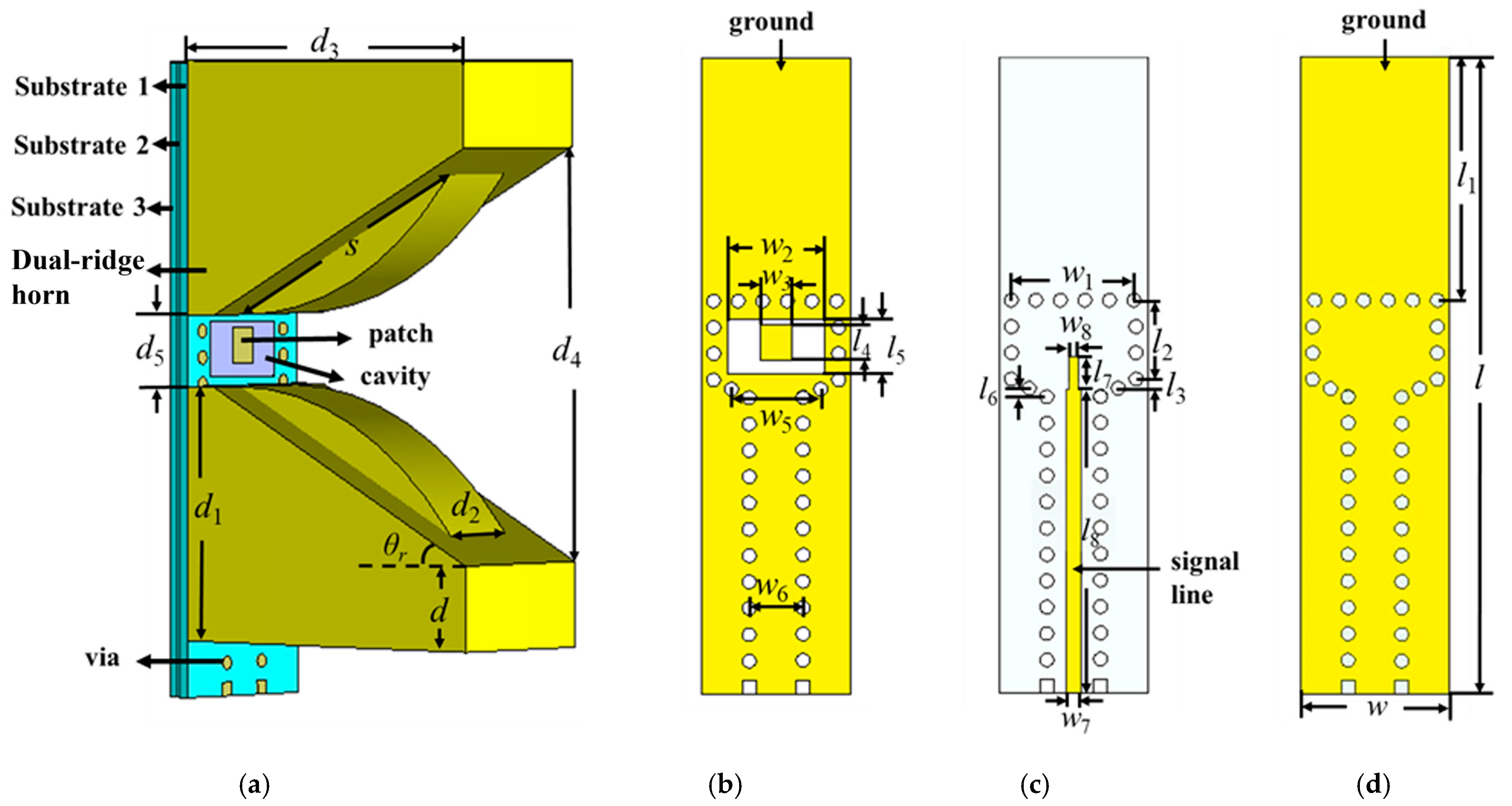
The proposed antenna element comprises a double-ridged horn, cavity-backed patch, and SICL feeding line, as depicted in Figure 3. The double-ridged horn is on the top of substrate 1. The patch is located on the top metal layer of substrate 1. The SICL signal line serves as a feeding line located under the patch. Considering the size of the cavity-backed patch, w and d5 are the width and length for the inner rectangular aperture. The distance between antenna elements is generally between λ0/2 and λ0. The H-shaped double-ridged horn is designed with the horn aperture width (d4) and the angle (θr). The curvature of the ridge along the longitudinal direction (x-axis) is determined by a modified exponential function [26]:
y ( x ) = a e k x 0 x s
where x represents the axial length along the horn, starting from the end of the ridge’s straight section, and s denotes the axial length of the ridge.
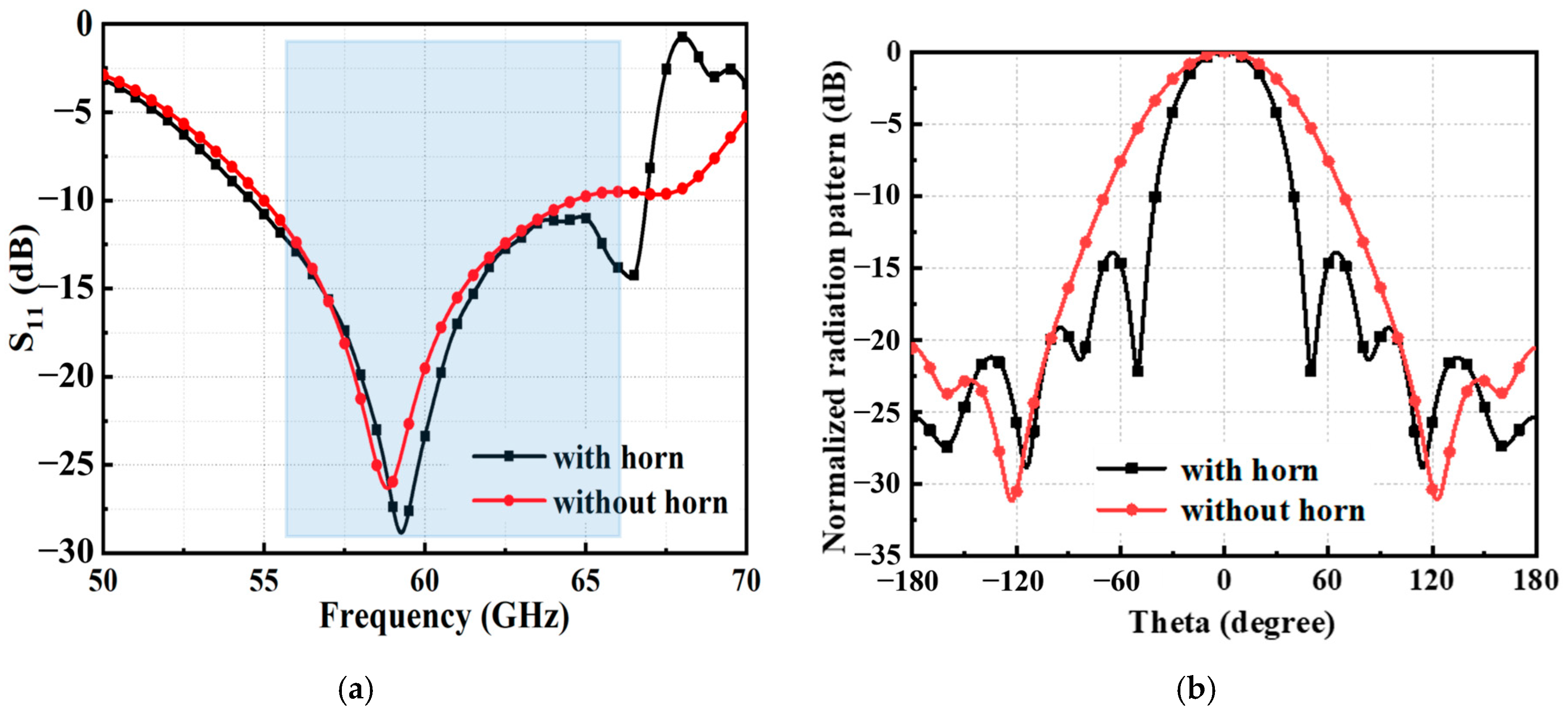
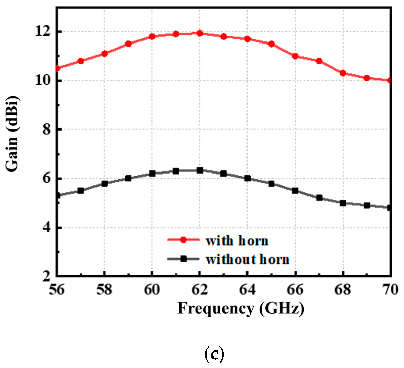
The design of the internal ridges within the pyramidal horn cavity serves a dual purpose. On one hand, it guides the transmission of the current further. On the other hand, it ensures impedance matching and gradual transition to the external air for effective impedance matching. These dimensions can be seen in Table 1. In Figure 4, the simulated −10 dB impedance bandwidths of the cavity-backed patch-loaded and -unloaded double-ridged horn are 9.6 GHz (55–64.6) and 12.3 GHz (54.6–66.9 GHz), respectively. The bandwidth of the cavity-backed patch antenna loading ridged horn is 2.7 GHz larger than that of the cavity-backed patch antenna without a double-ridged horn. The resonance within the double-ridged horn generates additional resonance points, thereby expanding the antenna’s bandwidth. The simulated gain of the loaded ridged horn is 10.8 dBi at 60 GHz, which increased 5.1 dB.

3. Design of Compact 4 × 4 Rotationally Symmetric Butler Matrix Based on SICL

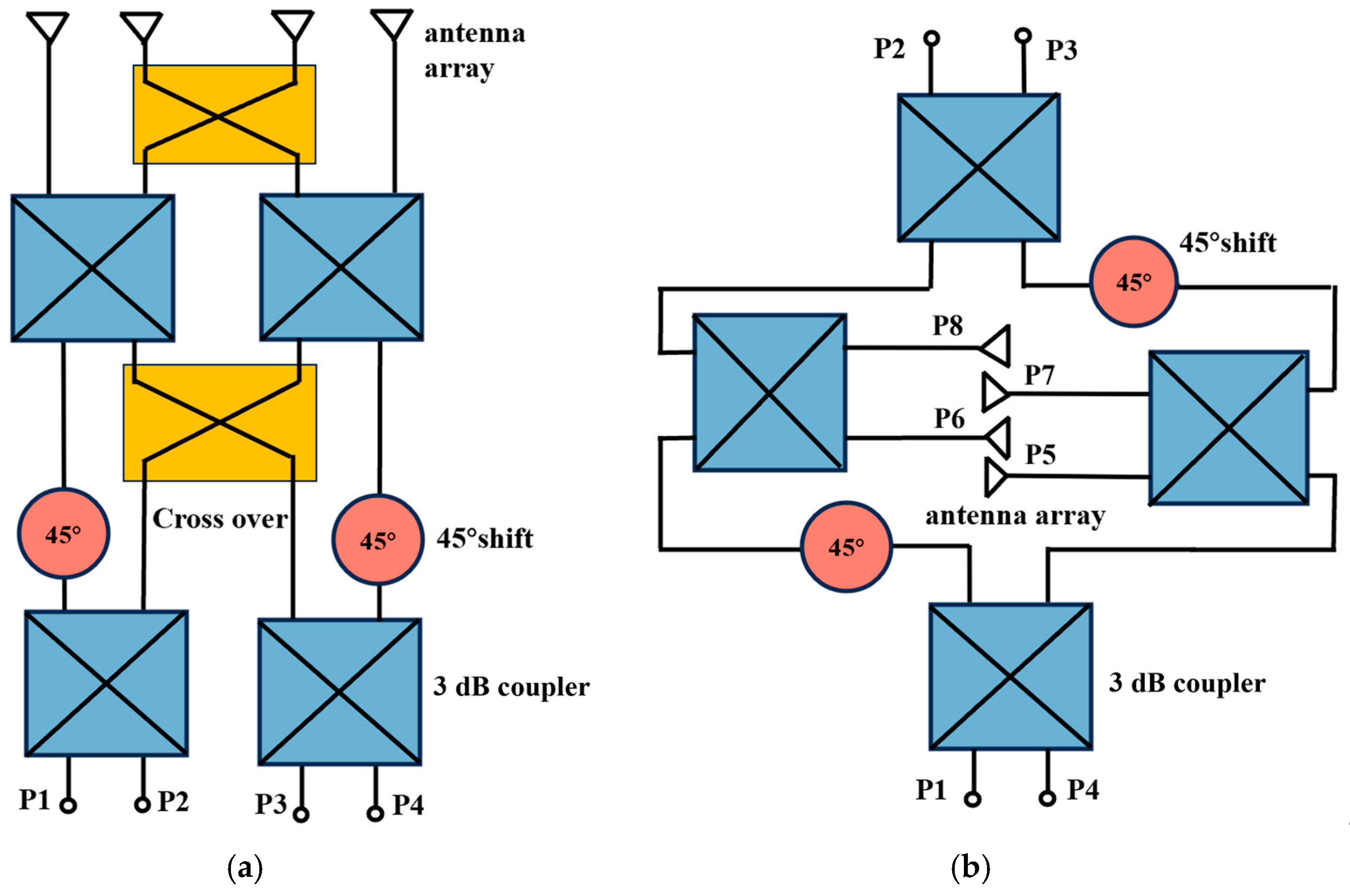
The schematic of the 4 × 4 symmetrical Butler matrix is composed of four 3 dB couplers, two 45° phase shifters, and two crossovers, as shown in Figure 5a. The rotational symmetry structure avoids using crossovers for miniaturized design, as shown in Figure 5b. The proposed rotationally symmetric Butler matrix, with its highly integrated design and placement beneath the radiators, enhances the compactness and interference-free characteristics of the presented antenna design.
To facilitate a clearer understanding of this design, the output ports are categorized into two groups: P5–P6 and P7–P8, with a progressive phase increment α assigned to the elements within each group. To meet the required phase difference between the adjacent ends of the two groups, the following criterion is established [27]:
α = β + 2 K π / 4
β = 2 M + 1 π
where β represents the phase difference between the outputs of the power splitters and K and M are integers. The phase increment α can take one of the following values: ±45° or ±135°, while β is set to π for simplification. Consequently, K is assigned the values −2, −1, 0, and 1, which correspond to the phases of P3, P1, P4, and P2, respectively.

3.1. Wideband 3 dB Three-Branch-Line Coupler with DGS

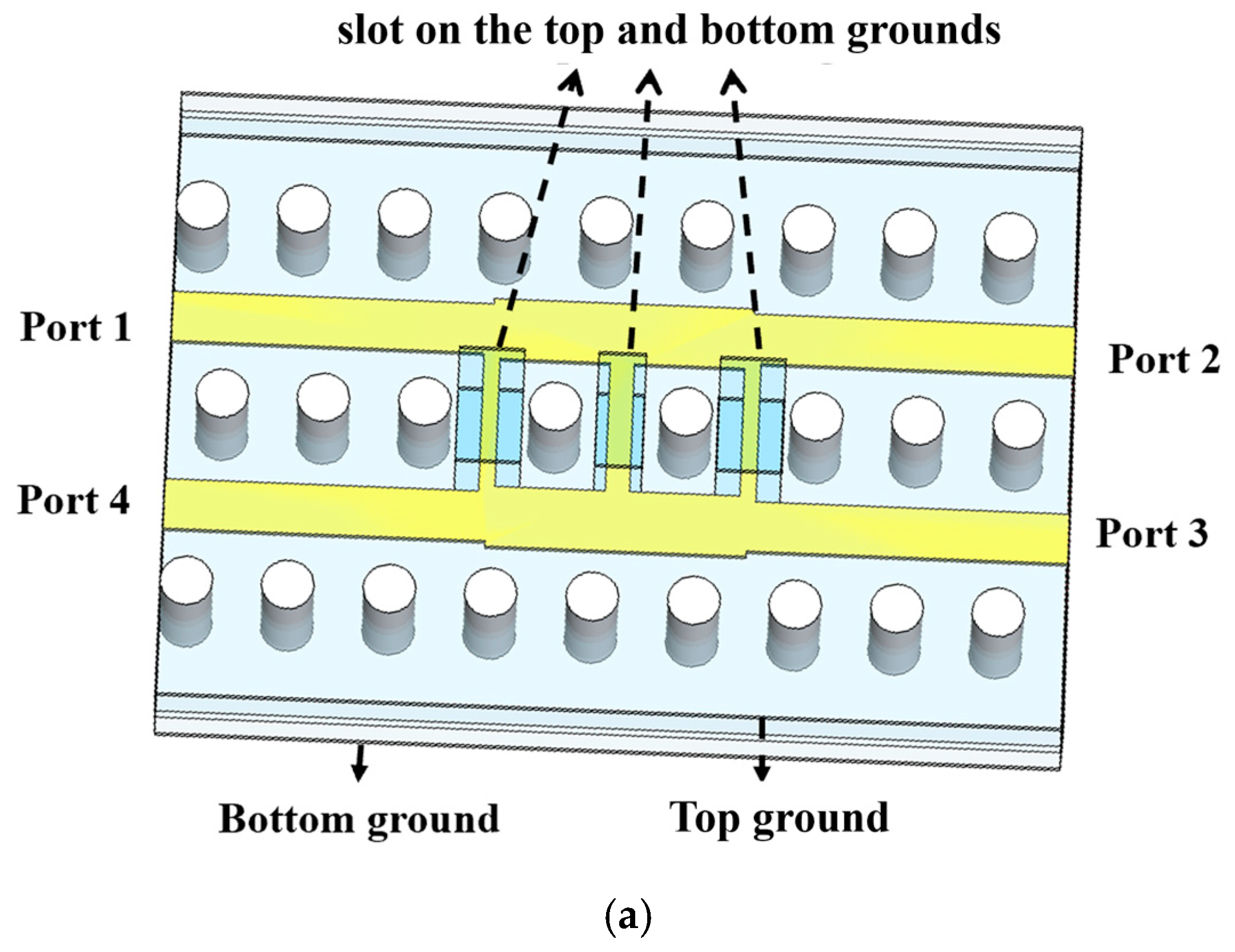
A planar 3 dB three-branch-line coupler with a DGS is proposed, as shown in Figure 6. A DGS can be realized by etching three rectangular slots on the top and bottom grounds. The DGS section increases the electrical length and provides a wider effective characteristic impedance compared to that of a conventional microstrip. The rectangular shape of the DSG is optimized to control the design of the coupler, as shown in Table 2. The phase difference between Port 2 and Port 3 is 90° ± 1°. The |S21| and |S31| are less than −3.5 dB that induces 0.5 dB of loss. The bandwidth of this three-branch 3 dB coupler ranges from 55 to 70 GHz (21%), as shown in Figure 7.

3.2. WR-15-to-SICL Transition

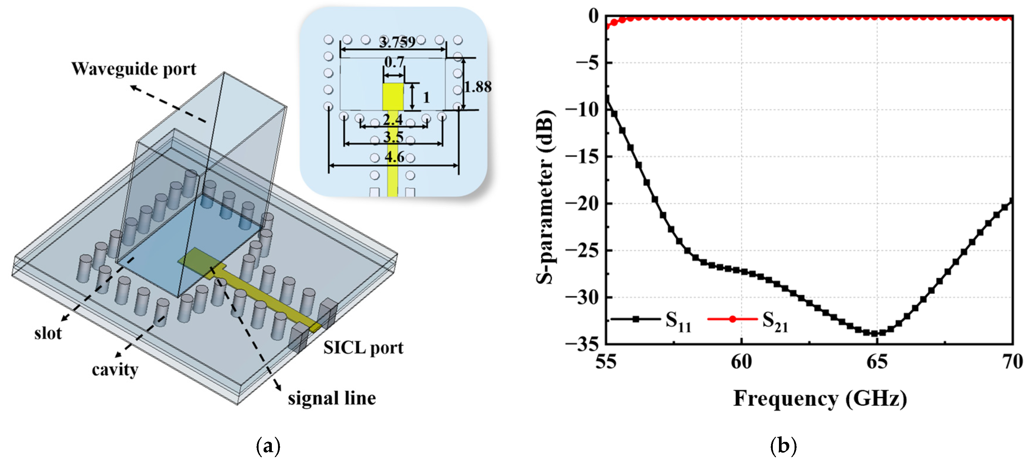
Figure 8a shows the overall structure of the SICL to waveguide (WR-15). The coupling aperture is etched on the top of the cavity, which consists of many metallic via holes. The inner conductor probe has a wider width than the SICL transition and makes the shape of the rectangular to achieve impedance matching. Figure 8b shows that the simulated |S11| is less than −20 dB and |S21| is more than −1 dB when the frequency ranges from 57 GHz to 68 GHz. This design can provide the BM with a convenient connection to waveguide measurement instruments in millimeter-wave applications.

3.3. 4 × 4 SICL Butler Matrix

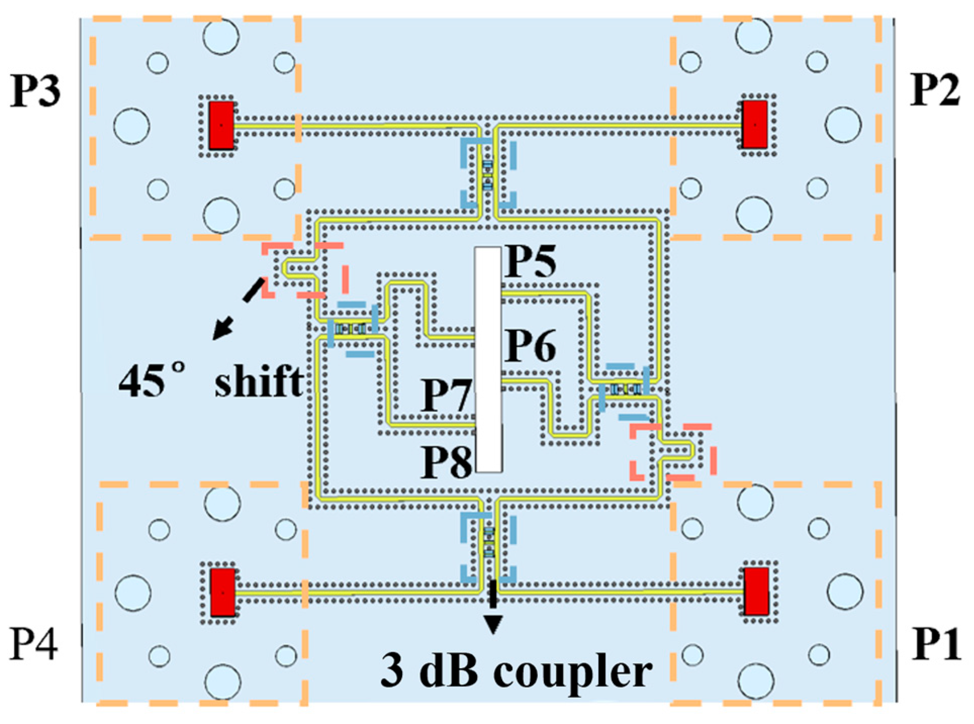
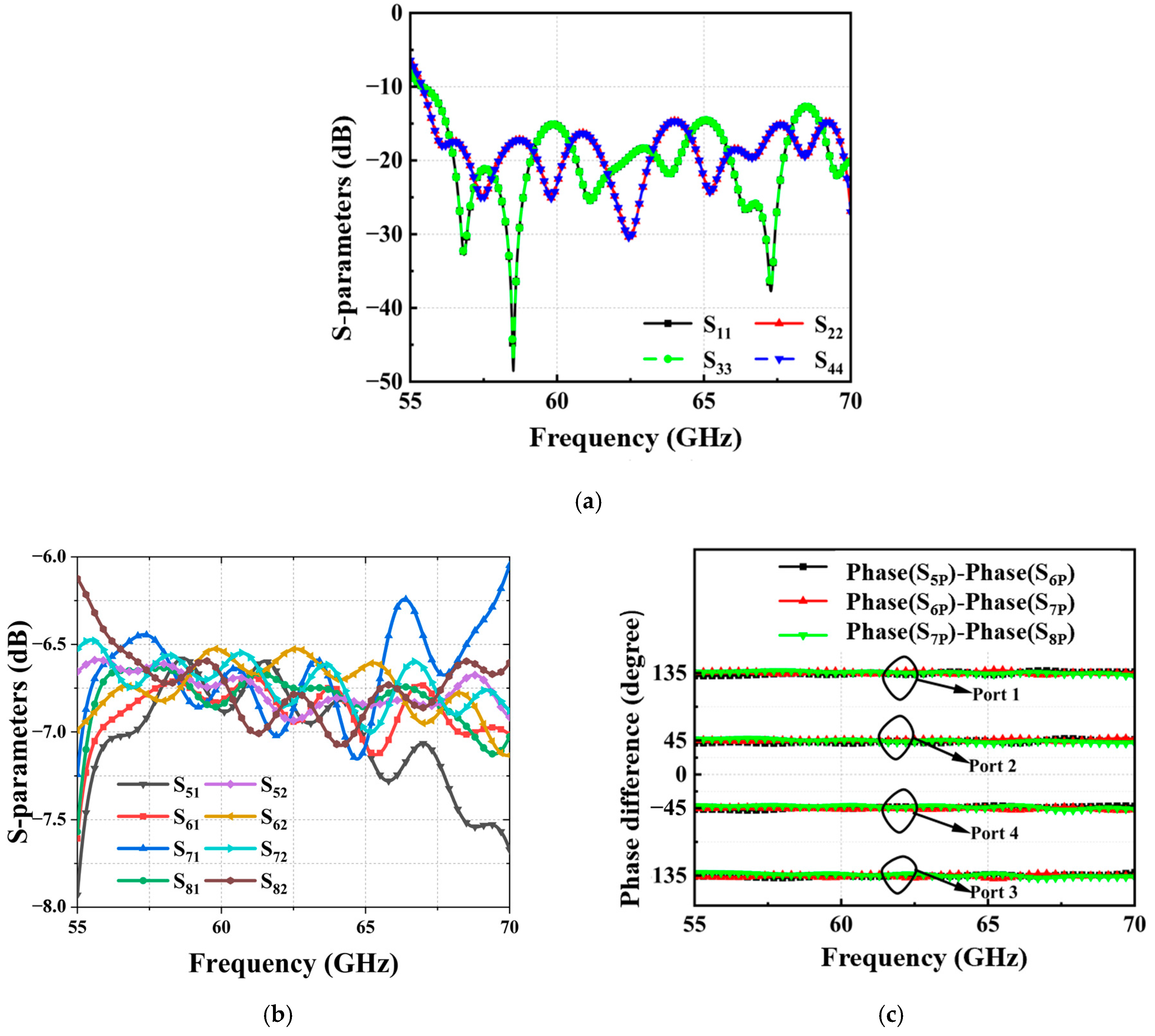
Figure 9 shows the topology of the proposed 4 × 4 rotationally symmetric BM, which comprises four 3 dB three-branch-line couplers with a DGS, two −45° phase shifters, and four WR-15-to-SICL transitions [28]. A designed 4 × 4 rotationally symmetric SICL BM occupies an area of 63 × 65 × 0.518 mm3. The simulated results of the SICL Butler matrix are shown in Figure 10. The simulated −15 dB impedance bandwidth is 17% (56–68 GHz). The magnitudes of |S51|, |S61|, |S71|, |S81|;|S52|, |S62|, |S72|, and |S82| are less than −6.8 ± 0.8 dB. Due to the symmetry of the SICL Butler matrix, the insertion loss of other ports is omitted. The phase differences among different output ports are −45°, 45°, −135°, and 135° with phase fluctuations within ±5° over the frequency range. The phase differences of the designed BM meet the requirements of a beam-scanning antenna array.

4. Design of Non-Uniform Double-Ridged Horn Antenna Array

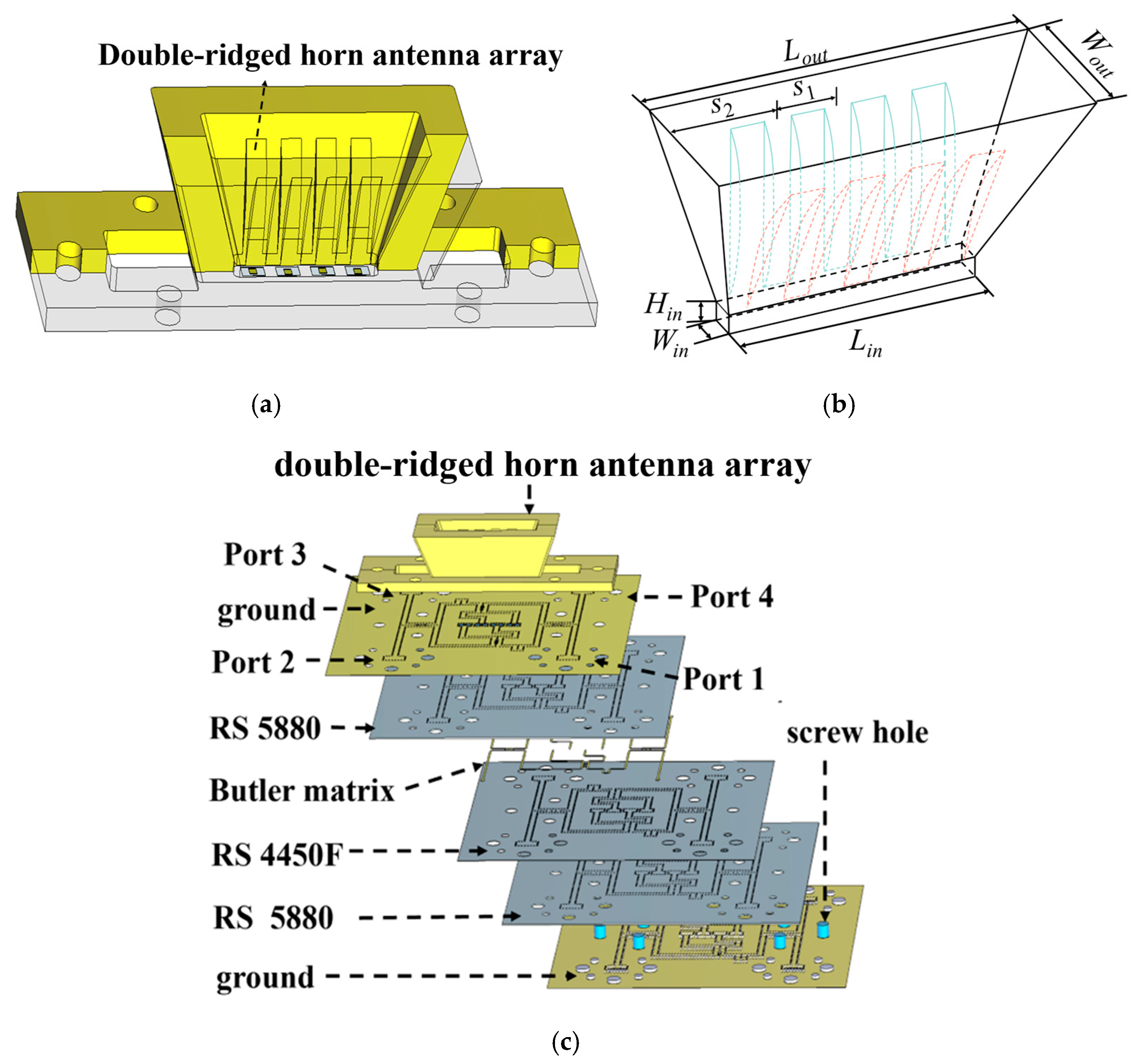
In Figure 11, the cavity-backed antenna and Butler matrix are positioned within the substrate, while the dual-ridged horn antenna array is secured to the substrate using screw holes. The BM generates a beam-scanning performance, but also produces high sidelobes. The traditional uniform horn antenna array has the same aperture and element distance. The non-uniform horn antenna array consists of two types of double-ridged horn apertures with S1 and S2. The aperture of the double-ridged horn antenna elements on both sides is extend outward, which is equivalent to introducing a phase difference between the double-ridged horn elements of different apertures. The non-uniform element distribution improves the sound field pattern and optimizes the energy distribution, which achieving a low sidelobe effect. Wout and Lout are the width and length for the inner rectangular aperture of the horn array. These dimensions can be seen in Table 3.
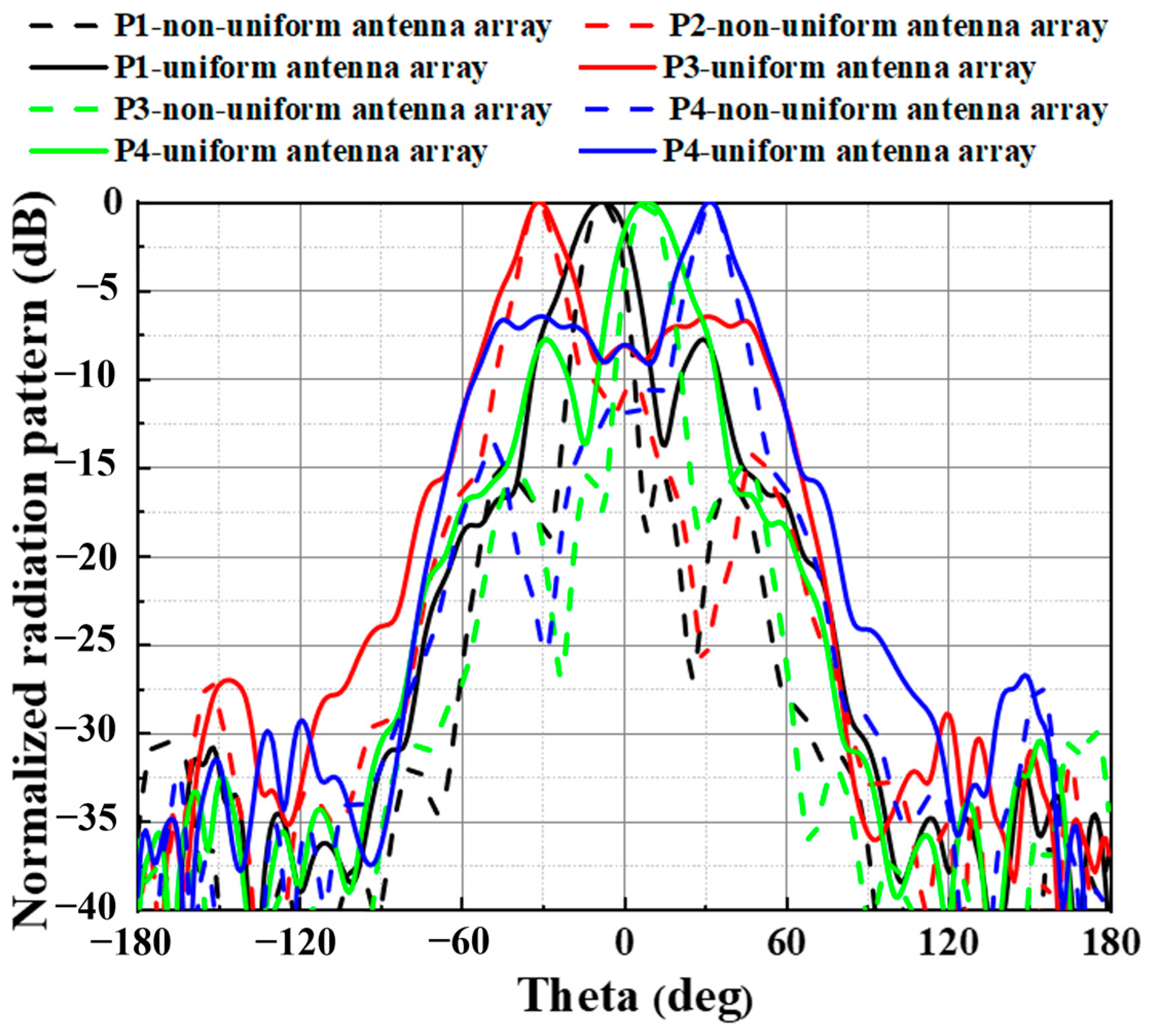
The beams of the non-uniform double-ridged horn antenna array can scan up to angles of −31°, −7°, 8°, and 32° at 62 GHz and a half-power beamwidth (HPBW) of 19°~23° and an SLL lower than −14.4 dB, as illustrated in Figure 12. The non-uniform double-ridged horn antenna array reduces the sidelobe level by −7. dB compared to the uniform array.

5. Measurement and Discussion

The fabricated prototype of the proposed beam-scanning antenna array is shown in Figure 13a,b. In this processing accuracy, the minimum line width for multi-layer boards is 3.5 mil (0.0889 mm) and the minimum line spacing is 6 mil (0.153 mm). Therefore, this processing accuracy can meet the minimum line width design requirement. The gain measurement setup is depicted in Figure 13c and operates in a microwave anechoic chamber, with each input port fed individually while the remaining ports are terminated using 50-ohm loads. The size of the 4 × 4 rotationally symmetric BM and non-uniform double-ridged horn antenna array is 63 × 65 × 0.512 mm3 and 55 × 17.7 × 11.5 mm3, respectively.
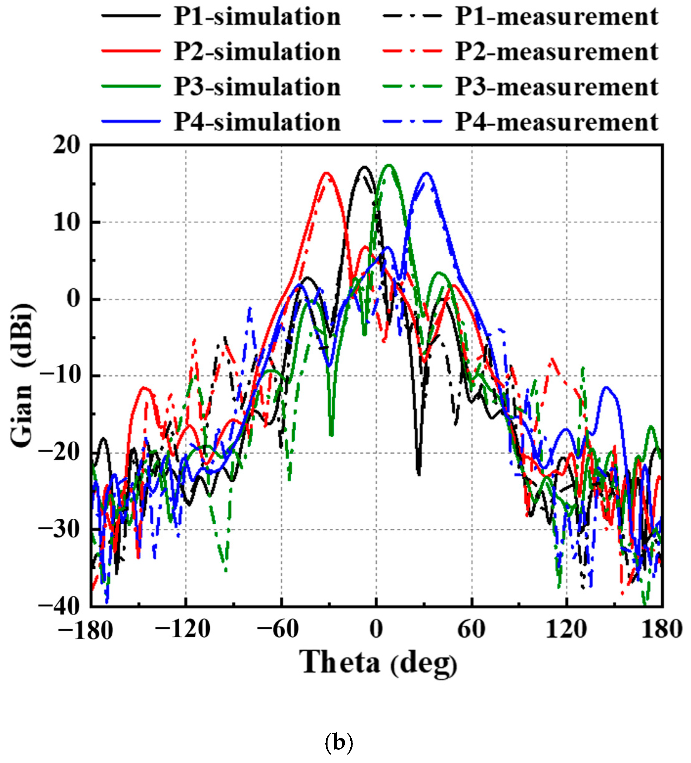
From 55.4 to 70 GHz, the measured |S11|, |S22|, |S33|, and |S44| are better than −10 dB as shown in Figure 14a. The simulated beam directions are −31°, −7°, 8°, and 32° with gains of 16.5, 17.1, 17.2, and 16.1 dBi at 62 GHz. The measured beam directions are −30°, −9°, 10°, and 30°. The measured gains fed in four input ports are 15.4, 16, 16.1, and 15 dBi at 62 GHz. The measured gains of the beams are slightly lower than the simulated gains due to losses from the waveguides used in the measurement connections. The measured loss of the straight waveguide is approximately −0.52 dB at 62 GHz. Due to the CCR antenna measurement, the overall loss is doubled up to −1.04 dB at 62 GHz. Therefore, the −1~−1.4 dB decrease in gain between the simulation and measurement is due to waveguides. The simulated results, after accounting for measurement losses, closely match the measurement results.
The characteristics and performance metrics of the proposed and previously reported millimeter-wave beam-scanning antenna arrays are summarized in Table 4. The operating bandwidth of the proposed array is broader compared to other designs operating at 62 GHz. Furthermore, due to the low-loss characteristics of the SICL Butler matrix, high gains and compact performances are achieved in this work. This indicates that it is of value for 5G wireless communication.

6. Conclusions

A wideband beam-scanning antenna array based on a compact 4 × 4 SICL BM is proposed for 60 GHz applications. The design integrates a non-uniform double-ridged horn antenna array and a 4 × 4 rotationally symmetric BM, for compact and efficient implementation. Beam-scanning performance is achieved through both simulations and measurements. The simulated and measured results exhibit good agreement with a 23.3% bandwidth and a 15 to 16.1 dBi gain. The measured beam directions are −30°, −9°, 10°, and 32°. Compared to other beam-scanning antenna arrays, the proposed antenna array offers unique advantages of a wideband and high gains. This makes it highly suitable for base-station applications in 5G wireless communication systems.

Author Contributions

Conceptualization, Z.H.; methodology, Z.H.; validation, C.G. and J.P.; data curation, C.G.; writing—original draft and preparation, Z.H. and C.G.; writing—review and editing, Z.H. and J.P.; project administration, S.F. and Z.Q. All authors have read and agreed to the published version of the manuscript.

Funding

This work was supported in part by the Shenzhen Higher Education Institutions Stabilization Support Program Surface Project (20220810153439004), the Key R&D Program of the Ministry of Science and Technology (2019YFB2204500), and Shenzhen Peacock Team Project (KQTD20180412181422399).

Data Availability Statement

The original contributions presented in this study are included in the article. Further inquiries can be directed to the corresponding author.

Acknowledgments

The authors would like to express their gratitude to the valuable feedback and suggestions provided by the editors and reviewers of this paper, which significantly improved the overall quality of the manuscript.

Conflicts of Interest

The authors declare no conflict of interest.

References

  1. Roh, W.; Seol, J.-Y.; Park, J.; Lee, B.; Lee, J.; Kim, Y.; Cho, J.; Cheun, K.; Aryanfar, F. Millimeter-wave Beamforming as An Enabling Technology for 5G Cellular Communications: Theoretical Feasibility and Prototype Results. IEEE Commun. Mag. 2014, 52, 106. [Google Scholar] [CrossRef]
  2. Butler, J.; Lowe, R. Beamforming matrix simplifies design of electronically scanned antennas. Electron. Des. 1961, 9, 170. [Google Scholar]
  3. Ren, H.; Zhang, H.; Jin, Y.; Gu, Y.; Arigong, B. A Novel 2-D 3×3 Nolen Matrix for 2-D Beamforming Applications. IEEE Trans. Microw. Theory Tech. 2019, 67, 4622. [Google Scholar] [CrossRef]
  4. Tseng, C.H.; Chen, C.J.; Chu, T.H. A Low-Cost 60-GHz Switched-Beam Patch Antenna Array with Butler Matrix Network. IEEE Antennas Wirel. Propag. Lett. 2008, 7, 432. [Google Scholar] [CrossRef]
  5. Yang, Q.-L.; Ban, Y.-L.; Lian, J.-W.; Yu, Z.-F.; Wu, B. SIW Butler Matrix with Modified Hybrid Coupler for Slot Antenna Array. IEEE Access 2016, 4, 9561. [Google Scholar] [CrossRef]
  6. Xiao, J.; Li, X.; Zhu, H.; Feng, W.; Yao, L. Micromachined Patch Antenna Array Design and Optimization by Using Artificial Neural Network. IEICE Electron. Express 2017, 14, 20170031. [Google Scholar] [CrossRef]
  7. Ma, L.; Wu, Y.; Wang, W. Design of Wideband Butler Matrix with Equal/Unequal Phase Differences for Flexible Beam-Controllability. IEEE Trans. Circuits Syst.-II Express Briefs 2021, 68, 3537. [Google Scholar] [CrossRef]
  8. Van Messem, L.; Moerman, A.; Caytan, O.; de Paula, I.L.; Hoflack, B.; Stroobandt, B.; Lemey, S.; Moeneclaey, M.; Rogier, H. A 4 × 4 Millimeter-wave Frequency Butler Matrix in Grounded Co-Planar Waveguide Technology for Compact Integration with 5G Antenna Arrays. IEEE Trans. Microw. Theory Tech. 2023, 71, 122. [Google Scholar] [CrossRef]
  9. Tian, G.; Yang, J.-P.; Wu, W. A Novel Compact Butler Matrix without Phase Shifter. Microw. Wirel. Compon. Lett. 2014, 24, 306. [Google Scholar] [CrossRef]
  10. Wu, Q.; Hirokawa, J.; Yin, J.; Yu, C.; Wang, H.; Hong, W. Millimeter-wave multibeam endfire dual-circularly polarized antenna array for 5G wireless applications. IEEE Trans. Antennas Propag. 2018, 66, 4930. [Google Scholar] [CrossRef]
  11. Vallappil, A.K.; Rahim, M.K.A.; Khawaja, B.A.; Murad, N.A.; Mustapha, M.G. Butler Matrix Based Beamforming Networks for Phased Array Antenna Systems: A Comprehensive Review and Future Directions for 5G Applications. IEEE Access 2021, 9, 3970. [Google Scholar] [CrossRef]
  12. Lian, J.-W.; Zhao, X.-Y.; Ban, Y.-L.; Liu, Y.; Nie, Z. Compact SIW 2-D Butler Matrix and Its Multibeam Application. IEEE Antennas Wirel. Propag. Lett. 2021, 20, 386. [Google Scholar] [CrossRef]
  13. Wu, M.; Zhang, B.; Zhou, Y.P.; Huang, K.M. A Double-Fold 7 × 8 Butler Matrix-Fed Multibeam Antenna with a Boresight Beam for 5G Applications. IEEE Antennas Wirel. Propag. Lett. 2022, 21, 516. [Google Scholar] [CrossRef]
  14. Qiu, L.-L.; Zhu, L.; Ouyang, Z.-A.; Deng, L. Wideband Butler Matrix Based on Dual-Layer HMSIW for Enhanced Miniaturization. IEEE Microw. Theory Tech. Soc. 2022, 32, 25. [Google Scholar] [CrossRef]
  15. Afifi, I.; Sebak, A.R. Wideband 4×4 Butler Matrix in the Printed Ridge Gap Waveguide Technology for Millimeter-Wave Applications. IEEE Trans. Antennas Propag. 2020, 68, 7670. [Google Scholar] [CrossRef]
  16. Tekkouk, K.; Hirokawa, J.; Sauleau, R.; Ettorre, M.; Sano, M.; Ando, M. Dual-Layer Ridged Waveguide Slot Array Fed by a Butler Matrix with Sidelobe Control in the 60-GHz Band. IEEE Trans. Antennas Propag. 2015, 63, 3857. [Google Scholar] [CrossRef]
  17. Wang, C.; Yao, Y.; Cheng, X.; Zhu, Z.; Li, X. A W-Band High-Efficiency Multibeam Circularly Polarized Antenna Array Fed by GGW Butler Matrix. IEEE Antennas Wirel. Propag. Lett. 2021, 20, 1130. [Google Scholar] [CrossRef]
  18. Li, X.; Hou, Y.; Zhu, H.; Qi, Z.; Xiao, J.; Cao, C. A Broadband Beam Scanning Antenna Array Based on Substrate Integrated Coaxial Line Butler Matrix for Q-Band Application. Microw. Opt. Technol. Lett. 2019, 61, 2781. [Google Scholar] [CrossRef]
  19. Li, W.; Xu, J.; Zhao, R.; Hong, W. Compact Broadband Substrate-Integrated Coaxial Line 2-D Beamforming Network and Its Multibeam Array Antenna Applications. IEEE Trans. Microw. Theory Tech. 2024, 27, 262. [Google Scholar] [CrossRef]
  20. Iqbal, A.; Tiang, J.J.; Wong, S.K.; Alibakhshikenari, M.; Falcone, F.; Limiti, E. Miniaturization Trends in Substrate Integrated Waveguide (SIW) Filters: A Review. IEEE Access 2022, 8, 223287. [Google Scholar] [CrossRef]
  21. Lian, J.W.; Ban, Y.L.; Xiao, C.; Yu, Z.F. Compact Substrate-Integrated 4×8 Butler Matrix with Sidelobe Suppression for Millimeter-Wave Multibeam Application. IEEE Antennas Wirel. Propag. Lett. 2018, 17, 928. [Google Scholar] [CrossRef]
  22. Trinh-Van, S.; Lee, J.M.; Lee, K.Y.; Hwang, K.C. A Sidelobe-Reduced, Four-Beam Array Antenna Fed by a Modified 4×4 Butler Matrix for 5G Applications. IEEE Trans. Antennas Propag. 2019, 67, 4528. [Google Scholar] [CrossRef]
  23. Lian, J.W.; Ban, Y.L.; Zhu, J.Q.; Guo, J.; Chen, Z. Planar 2-D Scanning SIW Multibeam Array with Low Sidelobe Level for Millimeter-Wave Applications. IEEE Trans. Antennas Propag. 2019, 67, 4570. [Google Scholar] [CrossRef]
  24. Tsai, C.-E.; Jin, H.; Liao, C.-H.; Li, C.-Y.; Chang, W.-C.; Liu, H.-E.; Chin, K.-S. A 60 GHz Rhombic Patch Array Antenna with High Gain, Low Sidelobe Level, and Reduced Array Area. IEEE Access 2022, 10, 86498. [Google Scholar] [CrossRef]
  25. Zhao, H.J.; Chu, H.; Zhu, X.H.; Guo, Y.X. A Butler Matrix-Based Antenna Array with Improved Gain Flatness and Sidelobe Levels by Using Pattern-Reconfigurable Subarrays. IEEE Antennas Wirel. Propag. Lett. 2022, 21, 2477. [Google Scholar] [CrossRef]
  26. Wang, C.; Li, E.; Zhang, Y.; Guo, G. Ridged Horn Antenna with Adjustable Metallic Grid Sidewalls and Cross-Shaped Back Cavity. IEEE Antennas Wirel. Propag. Lett. 2015, 15, 1221. [Google Scholar] [CrossRef]
  27. Cao, Y.; Chin, K.-S.; Che, W.; Yang, W.; Li, E.S. A Compact 38 GHz Multibeam Antenna Array with Multifolded Butler Matrix for 5G Applications. IEEE Antennas Wirel. Propag. Lett. 2017, 16, 2996. [Google Scholar] [CrossRef]
  28. Gao, C.; Peng, J.J.; Rui, H.D.; Zhu, H.; Fan, S.T.; Qian, Z.F. Wideband 4 × 4 Butler Matrix Based Substrate Integrated Coaxial Line for Millimeter-Wave Applications. In Proceedings of the Cross Strait Radio Science & Wireless Technology Conference, Haidian, China, 17–18 December 2022. [Google Scholar] [CrossRef]
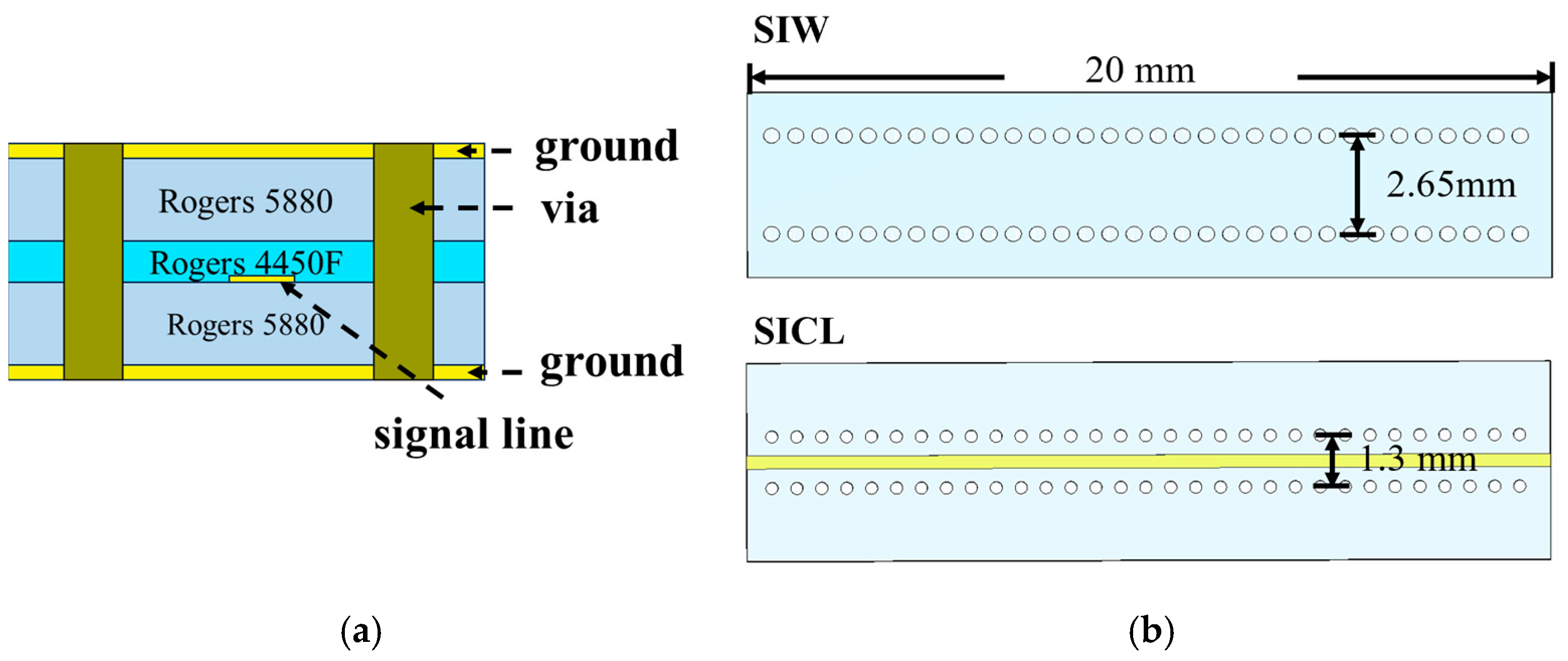
Figure 1. The configuration of SICL: (a) side view of SICL; (b) vertical views of SIW and SICL.
Electronics 14 00757 g001
Figure 2. The simulated |S21| of SICL.
Electronics 14 00757 g002
Figure 3. The cavity-backed ridged hybrid horn antenna element: (a) 3D model; (b) top metal layer of substrate 1; (c) top metal layer of substrate 3; (d) bottom metal layer of substrate 3.
Electronics 14 00757 g003
Figure 4. Simulated result: (a) |S11|; (b) simulated radiation patterns; (c) gain curve with frequency.
Electronics 14 00757 g004aElectronics 14 00757 g004b
Figure 5. Configuration of the 4 × 4 Butler matrix: (a) traditional Butler matrix; (b) rotationally symmetric Butler matrix.
Electronics 14 00757 g005
Figure 6. Planar 3 dB three-branch-line coupler with DGS: (a) 3D model; (b) signal line; (c) Top/bottom grounds.
Electronics 14 00757 g006aElectronics 14 00757 g006b
Figure 7. Simulation results of SICL 3 dB coupler: (a) S-parameter; (b) phase difference.
Electronics 14 00757 g007
Figure 8. The waveguide (WR-15)-to-SICL transition: (a) configuration; (b) simulated |S11| and |S12|.
Electronics 14 00757 g008
Figure 9. Configuration of SICL Butler matrix.
Electronics 14 00757 g009
Figure 10. Simulated results of SICL Butler matrix: (a) |S11|, |S22|, |S33|, and |S44|; (b) |S51|, |S61|, |S71|, |S81|;|S52|, |S62|, |S72|, and |S82|; (c) phase difference.
Electronics 14 00757 g010
Figure 11. Non-uniform double-ridged horn antenna array: (a) 3D view; (b) perspective view; (c) configuration.
Electronics 14 00757 g011
Figure 12. Simulated normalized radiation pattern of non-uniform and uniform antenna arrays.
Electronics 14 00757 g012
Figure 13. Fabricated prototype: (a) top view; (b) bottom view; (c) compensated compact range (CCR) antenna measurement environment.
Electronics 14 00757 g013aElectronics 14 00757 g013b
Figure 14. Simulated and measured results of proposed beam-scanning antenna array: (a) S-parameter; (b) radiation patterns at 62 GHz.
Electronics 14 00757 g014aElectronics 14 00757 g014b
Table 1. The optimal dimensions of antenna element (Unit: mm).
Parametersl1l2l3l4l5l6l7l8w1w2w3w4
Values5.741.860.220.831.30.20.597.182.832.30.732.11
Parametersw5w6d1d2d3d4d5θrslwd
Values0.360.25610371.724°7.32153.52
Table 2. The dimensions of 3 dB coupler with DGS (Unit: mm).
ParametersCw1Cw2Cw3Cw4CL1CL2Sw1Sw1SL
Values0.330.230.10.221.820.920.210.290.75
Table 3. The dimensions of non-uniform antenna array (Unit: mm).
ParametersLoutWoutHinLinWinS1S2
Values227114.51.73.54
Table 4. Comparison among different millimeter-wave beam-scanning antenna arrays.
Ref.TypeBMSize (λg)BandwidthGain (dBi)Beam (°)
[4]MS1 × 46 × 6 × 0.038.83%(@60GHz)7.7~8.9±14, ±40
[5]SIW4 × 411 × 4.2 × 0.0513%(@30GHz)9.7~12±12, ±51
[10]SIW4 × 437.5 × 2422.5%(@37.5GHz)10.4–12.8±13, ±38
[15]RGW4 × 49 × 5.421.25%(@30GHz)10.2~11.3±13, ±36
[16]RGW4 × 414.4 × 26 × 0.621.5%(@61.5GHz)25.1~26.3±17, ±43
This workSICL4 × 411 × 10 × 2.0323.3%(@62GHz)15.1~16.5−30°, −9°, 10°, 32°
Disclaimer/Publisher’s Note: The statements, opinions and data contained in all publications are solely those of the individual author(s) and contributor(s) and not of MDPI and/or the editor(s). MDPI and/or the editor(s) disclaim responsibility for any injury to people or property resulting from any ideas, methods, instructions or products referred to in the content.