Article

Study on Electromagnetic Focusing with Fully Phase-Adjustable High Transmittance Metasurface

School of Aeronautics and Astronautics, University of Electronic Science and Technology of China, Chengdu 611731, China
*
Author to whom correspondence should be addressed.
Electronics 2025, 14(4), 669; https://doi.org/10.3390/electronics14040669
Submission received: 20 January 2025 / Revised: 3 February 2025 / Accepted: 7 February 2025 / Published: 9 February 2025
(This article belongs to the Section Microwave and Wireless Communications)

Abstract

:
Electromagnetic beam focusing is usually controlled by phase. However, metasurfaces can effectively achieve phase control. This paper investigates electromagnetic focusing technology based on high-transmittance metasurfaces. Firstly, a high-transmittance metasurface unit was designed with an operating frequency of 10 GHz, a transmittance of over 80%, and a phase shift of 360°. Then, based on the phase compensation and lens focusing theory, a highly transparent metasurface array for electromagnetic focusing was obtained. Finally, through simulation verification, the half power bandwidth reached 10°, with a transmission efficiency of 43.2% @ 800 mm, and the feasibility of focusing was verified through the experiments.

1. Introduction

Electromagnetic focusing technology, as a revolutionary technology in the field of electromagnetic wave transmission, achieves precise focusing of electromagnetic waves at a certain point through electromagnetic regulation. Initially, this technology was applied to wireless power transmission to achieve maximum efficiency. At the same time, it can be extended to precise electromagnetic communication [1,2] and electromagnetic imaging [3,4], as well as wireless energy transmission [5,6] and other fields. In addition, electromagnetic focusing technology finely regulates the transmission of electromagnetic waves in free space, demonstrating precise control over the distribution of electromagnetic space and energy focusing points. It surpasses the boundaries of traditional electromagnetic transmission and can be applied to medical non-destructive testing [7], as well as material structure damage detection [8] and other fields, with broad application prospects. However, achieving precise electromagnetic focusing control in free space remains a challenge, and the relevant research should be conducted. Not only does it promote the development of electromagnetic focusing technology, but it also has the potential for interdisciplinary applications.
In 1949, Wehner conducted research on focusing antenna technology [9], opening a new chapter in electromagnetic focusing control. Bickmore tested the far-field pattern of a linear slot focusing array [10], enriching the theoretical knowledge of focusing antennas. J. W. Sherman et al. analyzed the electromagnetic field characteristics of antenna arrays during focusing [11]. The phenomenon of array antennas being able to focus in specific areas was revealed. However, traditional focusing antennas have many significant drawbacks, such as high design costs and complexity, as well as antenna processing.
The focused beam antenna based on electromagnetic metasurfaces, which achieves beam focusing through optimized structural design and materials, has the characteristics of low cost, low complexity, and high gain. Enoch et al. confirmed the crucial role of electromagnetic metasurfaces in high-gain focused beam antennas [12]. Jun Hu and his research team designed a periodic metamaterial structure [13], providing new ideas for the application of metamaterials in electromagnetic wave modulation, which has attracted widespread attention in the academic community.
Tae Heung Lim and his research team used a metasurface lens inspired by Moiré to adjust the electromagnetic power focus in the Fresnel near-field region, with a working frequency of around 5.8 GHz and a focusing distance of about 40 cm [14]. Zhiwei Sun et al. used metamaterials to construct a zero OAM system for electromagnetic field modulation focusing, achieving energy focusing at 120 mm [15]. Yongqiang Liu, Wenqiang Chen et al. designed a symmetrical split ring resonator (SRR) phase gradient element surface to achieve electromagnetic wave focusing. At a working frequency of 12 GHz, the focusing distance is about 120 mm [16]. Song Wu, Yihang Zhang, and others utilized anisotropic metasurfaces with independent phase control under two orthogonal polarizations to achieve EM focusing control, with a focusing distance of approximately 70 mm [17]. Meanwhile, other researchers have also utilized electromagnetic metasurface arrays to achieve beam focusing [18,19,20], but their focusing transmission efficiency is relatively lower. Based on the above, electromagnetic control has limited focusing distance and transmission efficiency. This paper conducts research on electromagnetic-modulation focusing technology to improve focusing distance and transmission efficiency.
Overall, the key to electromagnetic focusing control lies in the design of metasurfaces. With the deepening of research on electromagnetic metasurfaces, structures such as cross [21], slot [22], and multilayer [23] have been used to design electromagnetic metasurfaces with different phase shifts. However, electromagnetic beam focusing requires controlling the phase shift of electromagnetic metasurfaces. Ahmed H designed a three-layer metasurface array antenna [24], achieving a phase shift of 270° and attenuation of −4 dB. Li Long et al. proposed the Huygens metasurface element [25], with a phase shift of up to 350° but attenuation of −3 dB. Based on the above literature, electromagnetic metasurfaces have problems such as 360° phase shift and high transmittance. In the paper, high transmittance metasurfaces and beam focusing are studied, and the electromagnetic metasurface unit with a transmittance exceeding 90% and a 360° phase shift is designed. The beam control focusing is achieved, and the beam focusing transmission efficiency reaches 43.2% at 800 mm.
This paper is organized as follows. We investigate the methods of Electromagnetic Focusing in Section 2. In Section 3, design and simulation of metasurface units and arrays, as well as electromagnetic focusing testing and analysis. We present our conclusions about the work in Section 4.

2. Materials and Methods

A horn antenna was used as the radiation source and a metasurface array was used as the focusing control array. The composition diagram is shown in Figure 1, in which ( x s , y s , z s ) represents the coordinates of the radiation source, ( x m , y m , 0 ) represents the coordinates of any point in the metasurface array, F is the focal point, and z f is the focal length.
According to the Fresnel diffraction theory, metasurface arrays mainly include two functions: phase compensation and focusing control. The phase compensation is used to compensate for the electromagnetic waves radiated by the electromagnetic radiation source to the metasurface array, converting them into planar electromagnetic waves. The focus control is the process of controlling the focusing of electromagnetic waves at the focal point F.
Considering the radiation source as a point source, the distance from the radiation source to each point of the metasurface array is not consistent, resulting in phase differences at each point. Phase compensation is used to ensure that the radiation source radiates to all points of the metasurface array with a completely consistent phase. Therefore, the electromagnetic transmission distance from the radiation source to the metasurface array is compensated to ensure that the input electromagnetic waves of the metasurface array are plane waves.
Phase compensation [20]:
( x m , y m ) = k x m x s 2 + y m y s 2 + z s 2
where k is the wave vector, and ( x m , y m ) is the compensation phase of ( x m , y m , 0 ) at any point in the metasurface array.
The conversion of the electromagnetic radiation source to the plane wave is achieved through phase compensation, and then, the plane wave is focused using a lens.
According to the principle of lens focusing [26], the focusing control phase is
θ ( x m , y m ) = k 2 z f ( x m 2 + y m 2 )
where θ ( x m , y m ) is the focusing control phase at any point ( x m , y m , 0 ) in the metasurface array.
The phase shift of the metasurface array is a combination of phase compensation and focus control phase, that is,
φ ( x m , y m ) = ( x m , y m ) + θ ( x m , y m )
where θ ( x m , y m ) is the total phase at any point ( x m , y m , 0 ) in the metasurface array.

3. Results

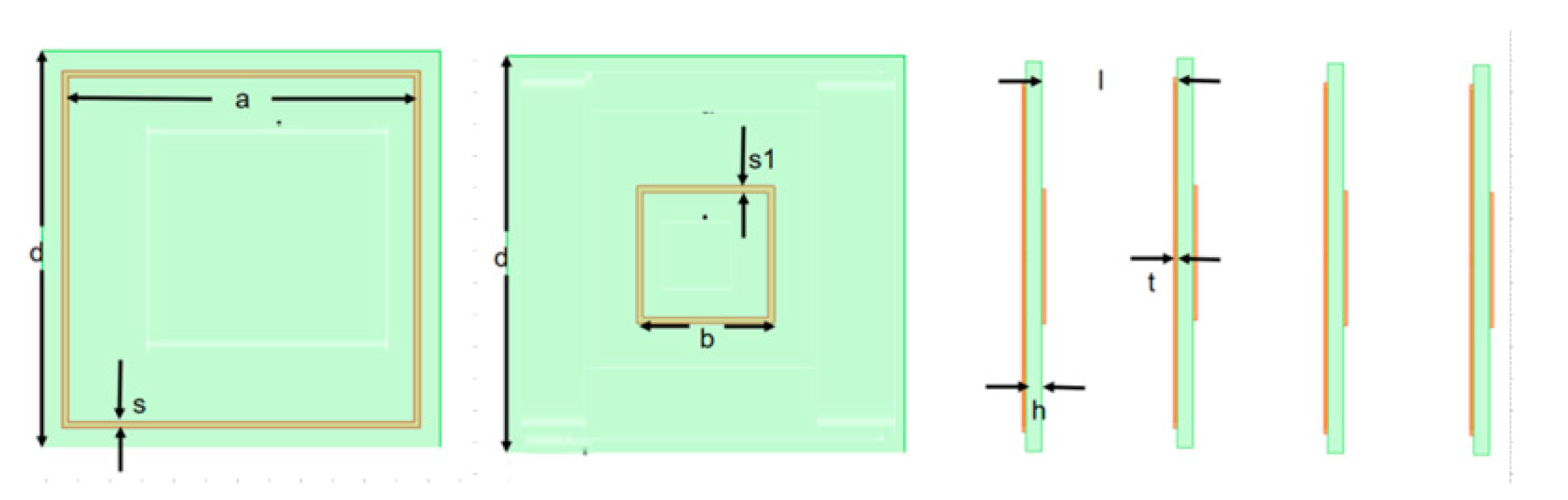
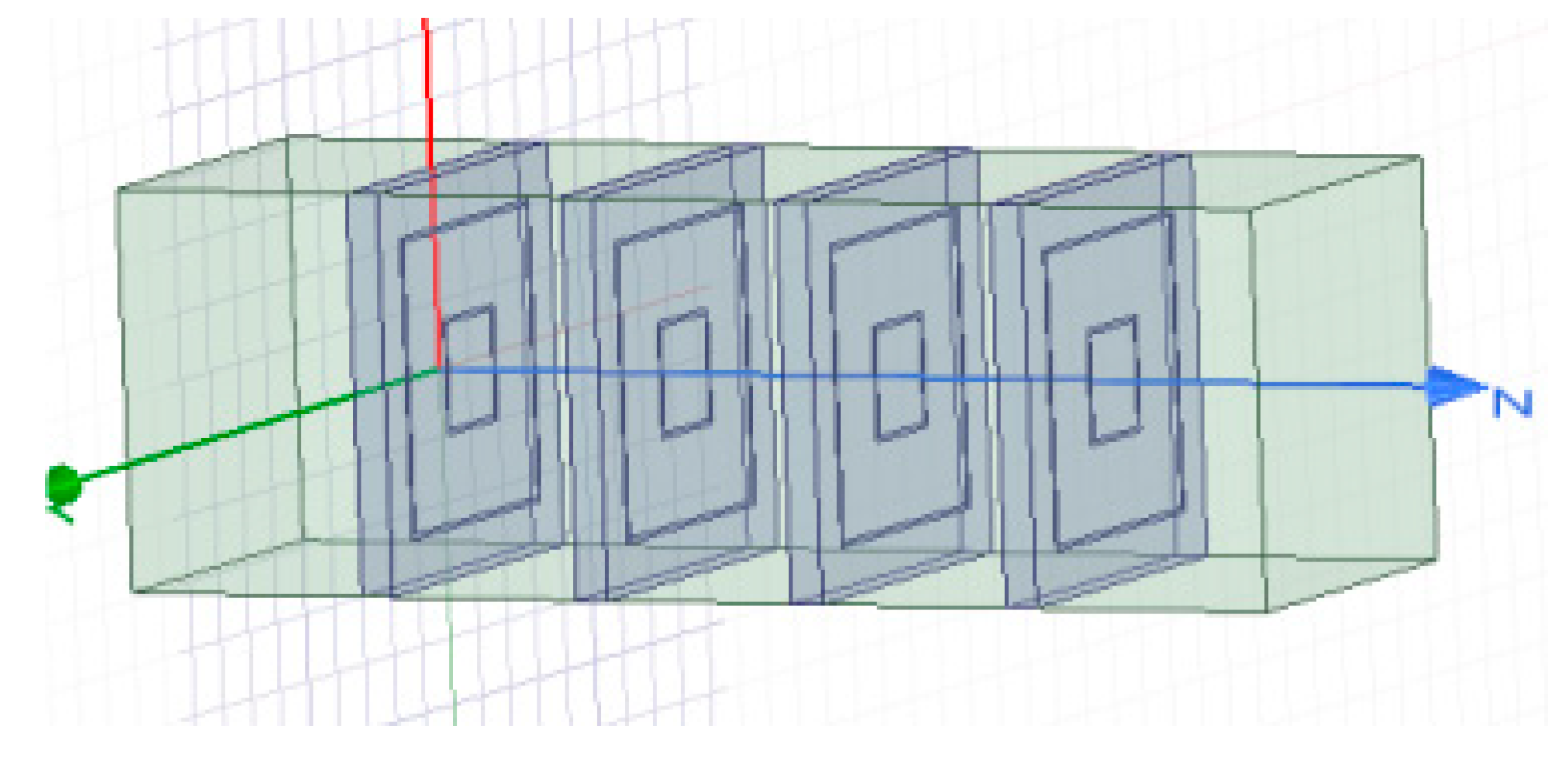
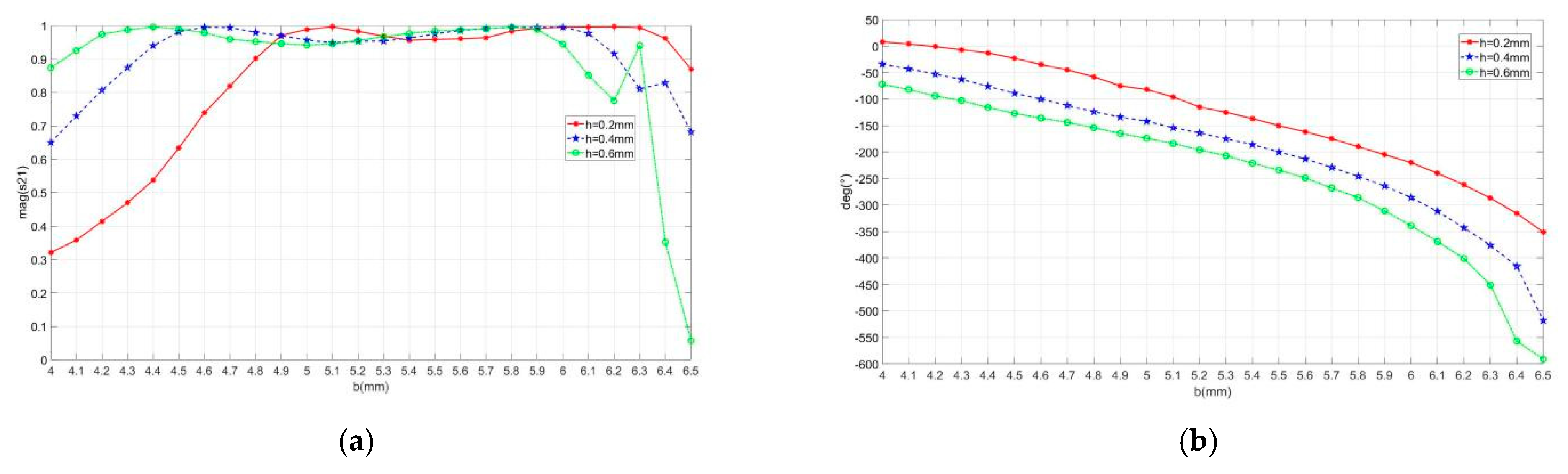
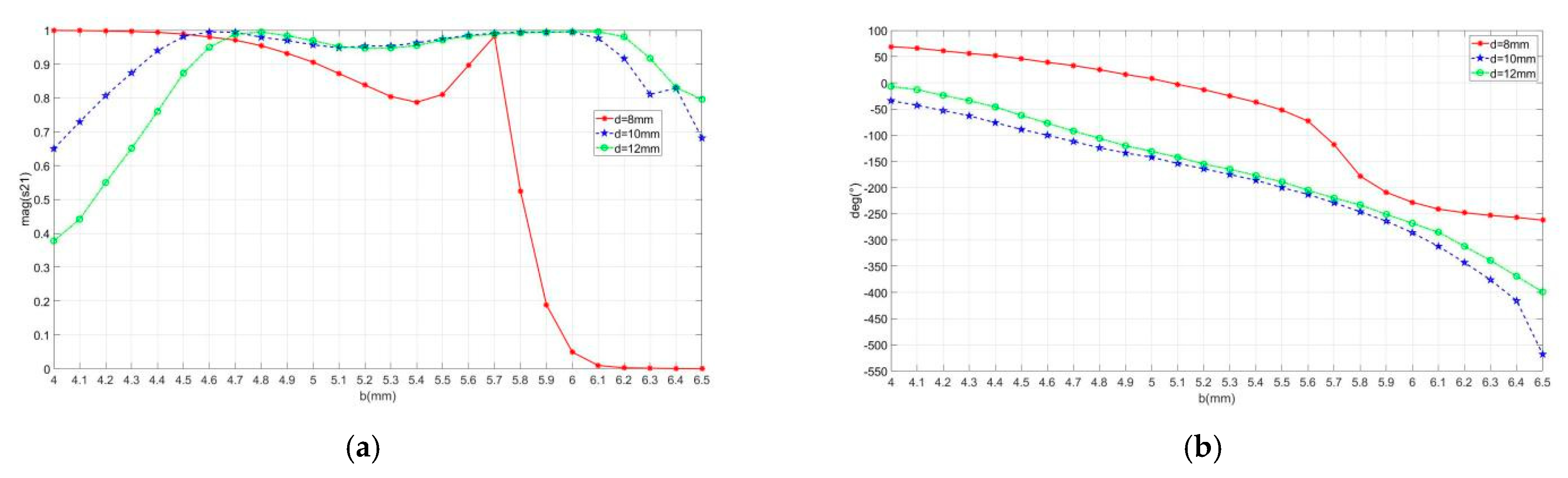
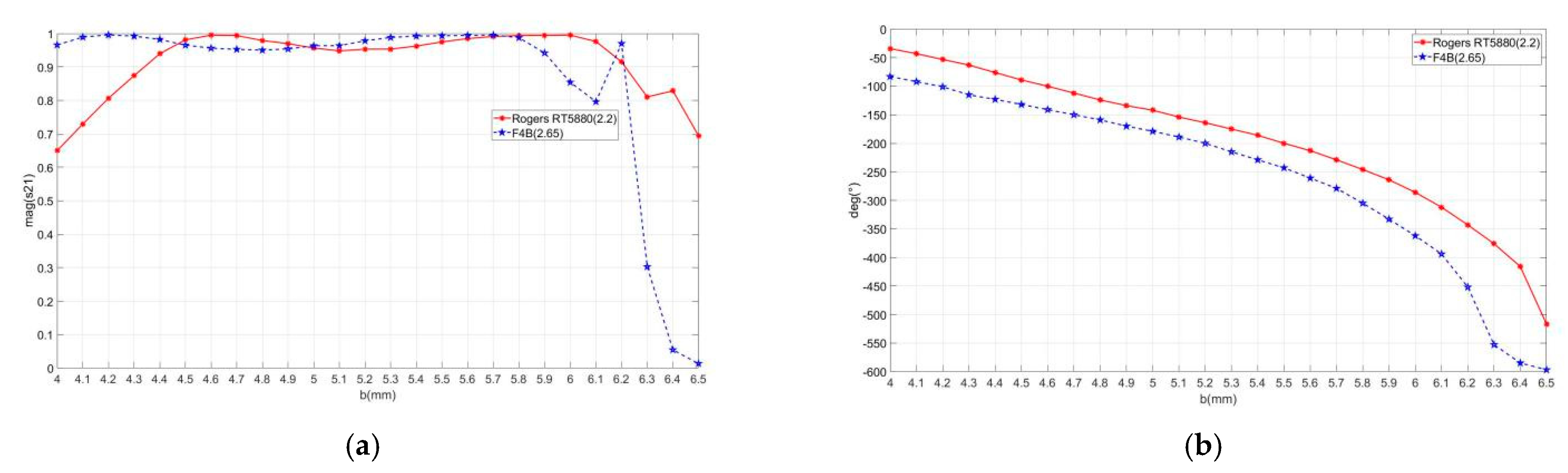
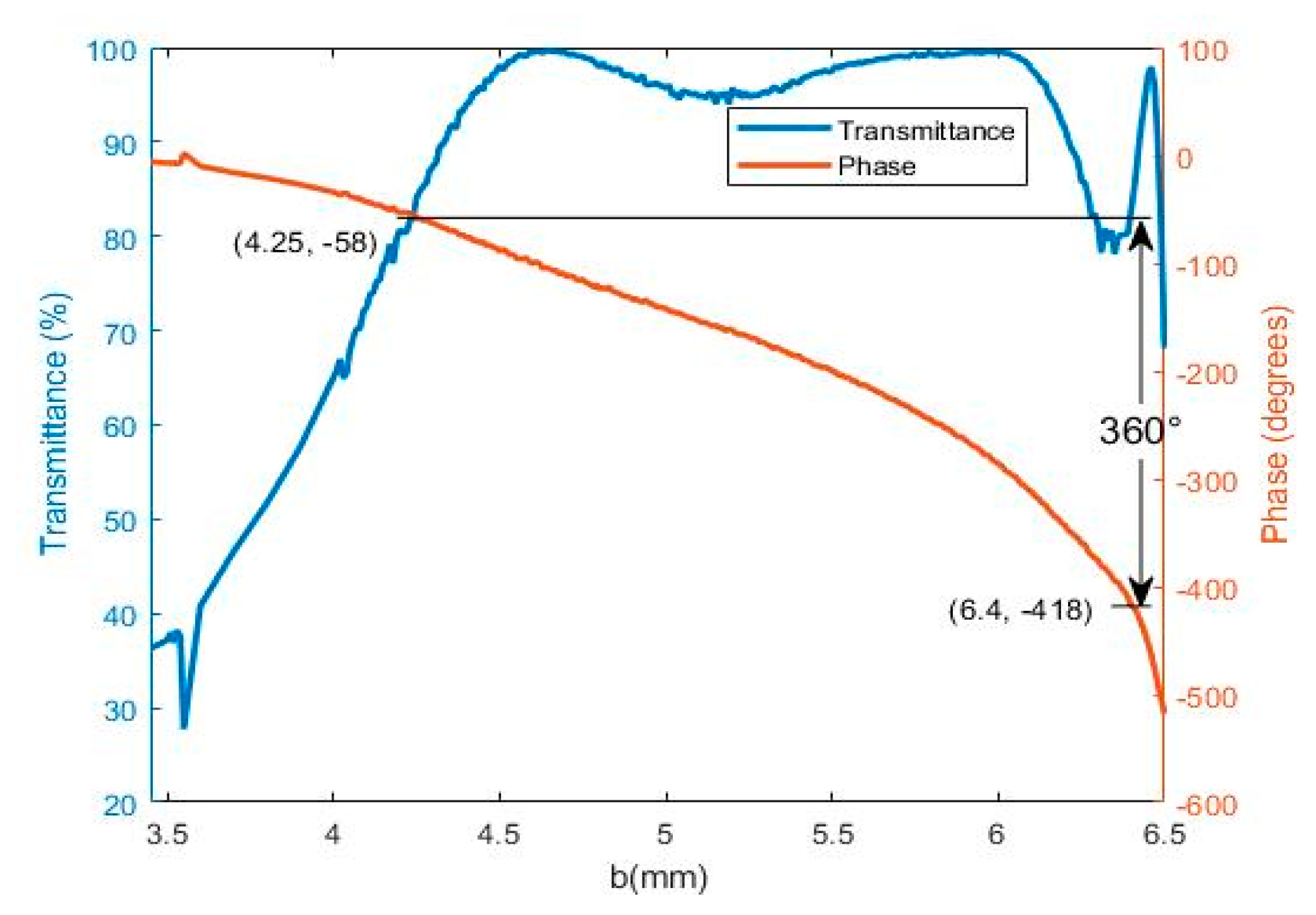
3.1. Design of Transmissive Metasurface Unit

According to the requirements of focusing phase control, metasurfaces have high transmittance, 360° phase shift, and a working frequency of 10 GHz. In the paper, the dual-sided metal ring structure is adopted, as shown in Figure 2. The top metal ring has a length of a and a width of s. The length of the bottom metal ring is b, the width is s1, the edge length of the metasurface unit is d, and the thickness of the copper layer is t. Four metasurface structures are arranged in parallel at intervals of l, forming four layered metasurface units. By adjusting length d of the lower metal inner ring in the metasurface structure, phase shift can be achieved. Using HFSS for simulation analysis, the simulation model of the metasurface unit is shown in Figure 3.
According to the metasurface structure, a and b mainly control the lower and upper cutoff frequencies of metasurface units, and their attenuation and phase shift are mainly affected by the interlayer gap width, substrate thickness, unit edge length, and substrate dielectric material of the metasurface. Therefore, the length a of the upper metal ring is set to 9 mm, the width s is set to 0.15 mm, and the width s1 of the lower metal ring is set to 0.15 mm. The range of length d of the lower metal ring is 4–6.5 mm, which meets the frequency requirement of 10 GHz. The effects of interlayer gap width, substrate thickness, unit edge length, and substrate dielectric material are analyzed to obtain the optimal metasurface unit.
Through HFSS simulation, the effects of interlayer gap width, substrate thickness, unit edge length, and substrate dielectric material on transmission loss and phase shift are shown in Figure 4, Figure 5, Figure 6 and Figure 7, respectively. From the analysis of Figure 4, Figure 5, Figure 6 and Figure 7, it can be seen that when the interlayer air gap width l is 0 and 3 mm, the phase shift cannot satisfy 360°, and the attenuation is larger. Only when the interlayer air gap width l is 6 mm, the transmittance of the metasurface unit exceeds 80% within the range of 4.2–6.4 mm for the lower metal ring length d, and the transmittance of most metasurface units exceeds 90%, with a phase shift of 360°. When the thickness h of the dielectric substrate is 0.2 mm, the phase shift cannot meet 360°. When h is 0.6 mm, the attenuation of some metasurface units is larger, such as d being 6.1 mm. Only when h is 0.4 mm, the transmittance of the metasurface unit exceeds 80% within the range of 4.2–6.4 mm, and the phase shift satisfies 360°. When side length d of the dielectric element is 8 mm and 12 mm, the transmittance of certain dimensions of the metasurface is relatively lower, less than 50%. Only when d is 10 mm, the transmittance of the metasurface within the range of 4.2–6.4 mm exceeds 80%, and the phase shift satisfies 360°. Similarly, when Rogers RT5880 is chosen as the substrate material, the metasurface transmittance exceeds 80% within the range of 4.2–6.4 mm, and the phase shift satisfies 360°.
Based on the above simulation analysis, the optimal size of the metasurface unit is as follows: the air gap height l is 6 mm, the thickness h is 0.4 mm, the dielectric substrate material is Rogers RT5880, and the edge length d of the metasurface unit is 10 mm. The specific dimensions of the metasurface unit are shown in Table 1.
The transmission loss and transmission phase of the four-layer metasurface unit are shown in Figure 8. When b is changed from 4.25 mm to 6.4 mm, the transmission phase coverage range meets 360°, the transmittance always meets more than 80%, and the large partial transmittance is 90%, showing excellent transmission performance. Such a unit design can ensure that at an operating frequency of 10 GHz, the metasurface unit can achieve the best transmission performance and phase control effect.
Compared with several commonly used metasurface units in terms of attenuation and phase shift, the comparison results are shown in Table 2. Table 2 shows that the metasurface unit in this paper has a phase shift of 360° and loss of about −0.9 dB, which is superior to other metasurface units.

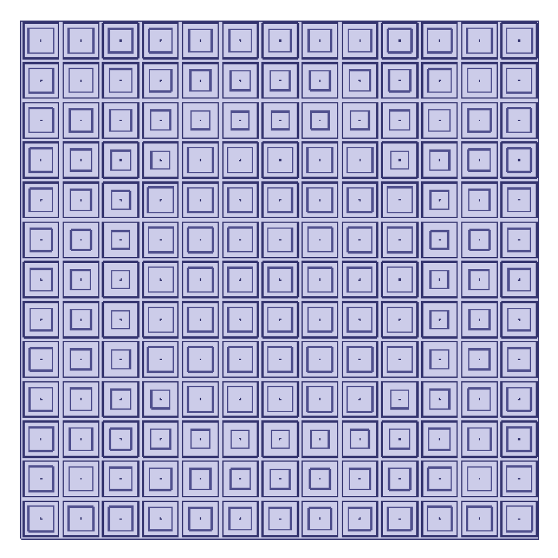
3.2. Design and Simulation of Focusing Array

A 13 × 13 metasurface array is constructed with an area of 130 mm × 130 mm. By using the principles of phase compensation and lens focusing, the phase of each unit in the array is obtained with a focusing distance of 800 mm, as shown in Table 3, Table 4 and Table 5. Table 3 shows the phase distribution of radiation source phase compensation, Table 4 shows the phase distribution of electromagnetic focusing control, and Table 5 shows the phase distribution of metasurface units, which is the combined phase of phase compensation and focusing control. The phase distribution diagram is shown in Figure 9. The metasurface units are designed in Part III to construct an array as shown in Figure 10, and the array simulation analysis platform is established using HFSS as shown in Figure 11. The horn antenna is used as the electromagnetic radiation source, with an electromagnetic wave frequency of 10 GHz and a power of 1 W. The distance between the metasurface array and the horn antenna radiation port is 80 mm, and an observation surface is set at 800 mm for focusing point testing.

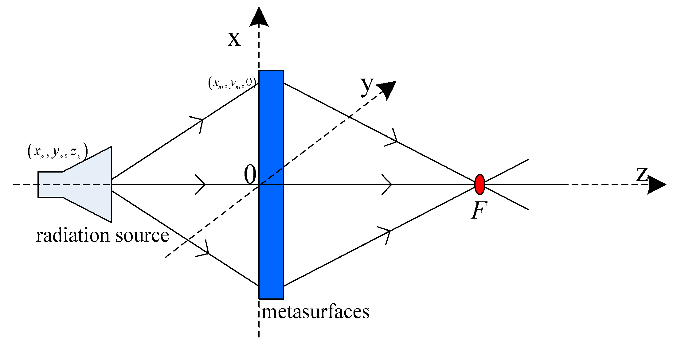
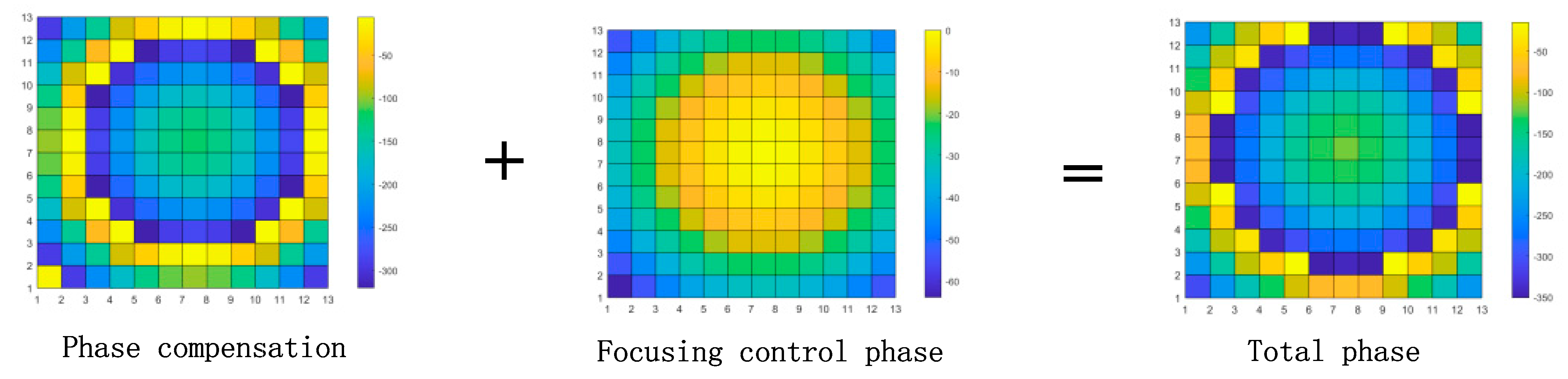
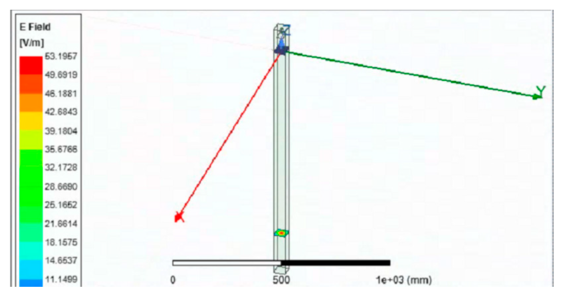
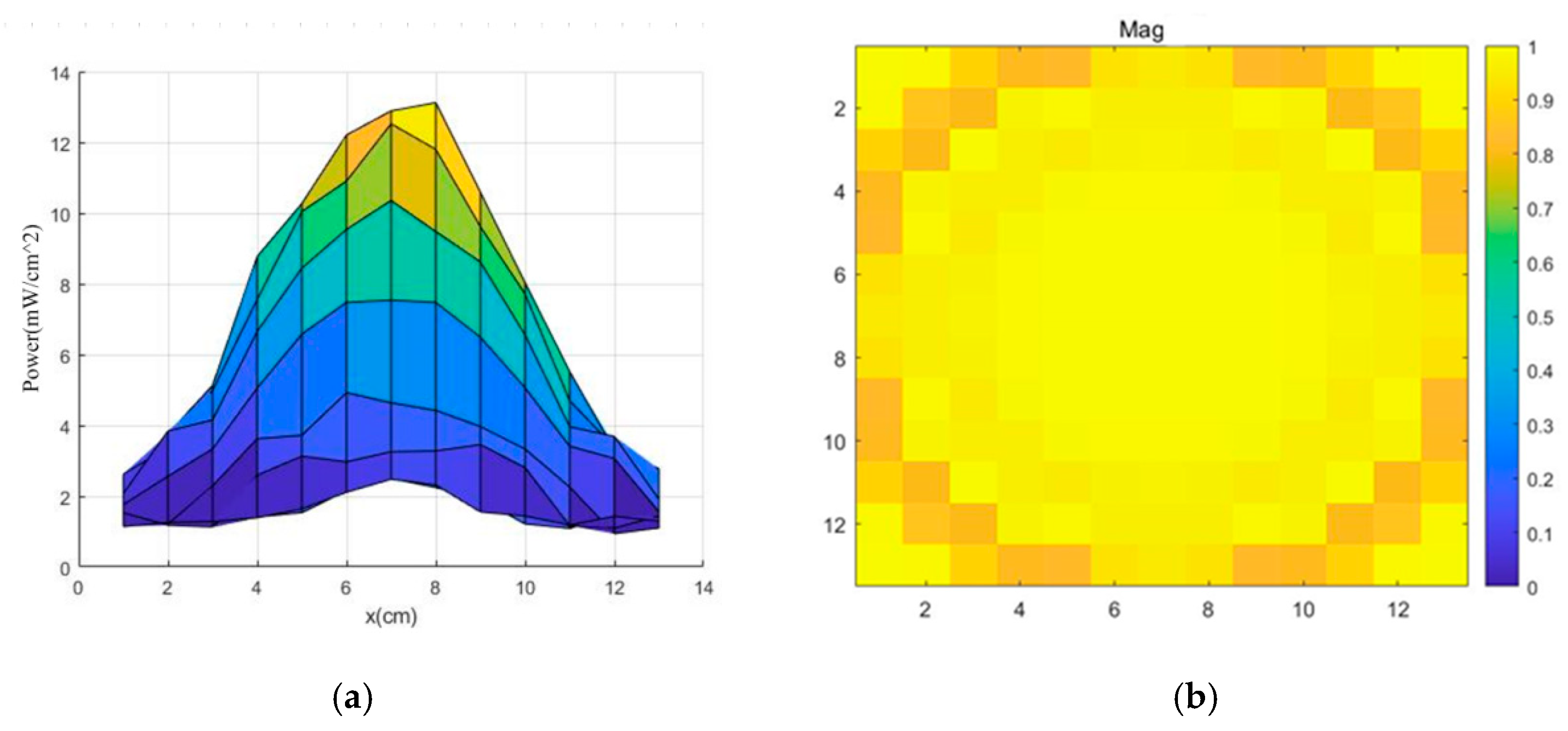
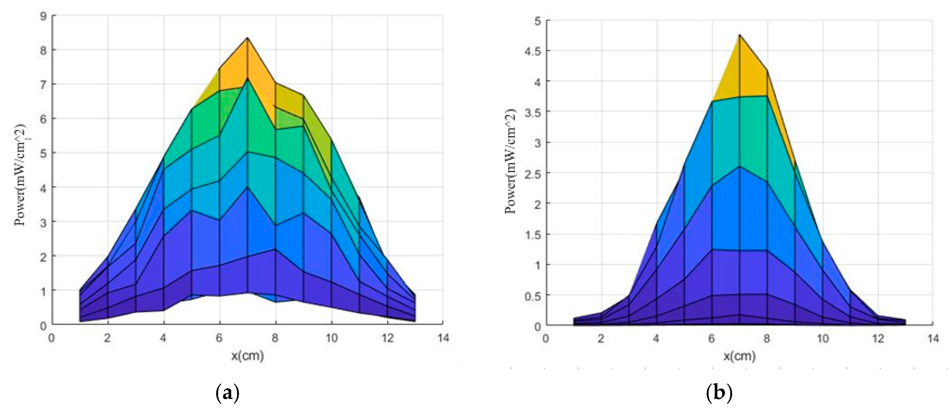
3.2.1. Analysis of Focusing

HFSS simulation was used to analyze the directional pattern of the metasurface array, as shown in Figure 12. Figure 12a shows the orientation diagram of placing a metasurface array, and Figure 12b shows the orientation diagram without placing a metasurface array. As shown in Figure 7, after focusing control through the metasurface array, the gain increased from 14.25 dBi to 19.81 dBi, and the half-power bandwidth decreased from 36° to 10°. Simultaneously, the focal point was analyzed at 800 mm, and the intensity distribution of the focal point is shown in Figure 13. According to the analysis of Figure 1, the diameter of the focused spot is approximately 6.5 cm.

3.2.2. Analysis of Array Transmission Efficiency

Regarding the transmission characteristics of metasurface arrays, the metasurface array is regarded as a four-port network, and the relationship between the output power and input power of electromagnetic waves through the metasurface array is shown in Equation (4):
P M = s 12 2 · P i n
where s 21 is the transmission coefficient, and P i n m and P M m are the incident power and output power of a metasurface unit on the array, respectively.
Using HFSS to simulate and analyze the transmission characteristics of the metasurface array, the observation surface was tested at a distance of 1 mm from the metasurface array. The test results are shown in Figure 14. The received power of the observation surface was calculated using the Poynting vector, which is about 941 mW, indicating that the metasurface array can reach over 94%.
Similarly, analyzing the transmission efficiency at the 800 mm focal point, the transmission efficiency formula is shown in Equation (5):
η = P o u t P i n
P o u t = S P p o w e r d d s
where S is the observation surface area, P p o w e r d is the observed surface power density, and η is the focusing efficiency.
By calculating the Poynting vector, the power distribution map of the focused observation surface is obtained, as shown in Figure 15a. By using Equation (6), the actual power is calculated to be 0.432 W, and its transmission efficiency can reach 43.2%. Similarly, when the metasurface array is not placed, the power distribution at 800 mm is shown in Figure 15b. The calculated power is 0.105 W, and the transmission efficiency is only 10.5%.

3.3. Experiment and Analysis

An experimental testing platform was constructed, as shown in Figure 16a, using the dual-ridge horn antenna with a working frequency range of 0.8–18 GHz as the transmitting and receiving ends. The metasurface array with dimensions of 130 mm × 130 mm was designed using the method described in Section 4. The physical object of the metasurface array is shown in Figure 16b,c, and the metasurface array was placed 80 mm above the transmitting antenna. The signal source generated a 1 mW signal, which was applied to the transmitting horn antenna and radiated onto the metasurface array. The metasurface array performed phase control, the signals were received from the receiving horn antenna, and the signal power intensity was read using a spectrum analyzer. A signal source was set up to output signals at different frequency points, and the frequency response of the metasurface array was tested. The frequency response is shown in Figure 16d. The analysis in Figure 16d shows that the frequency range was 9.2–10.3 GHz, and the test and simulation results are similar.
The metasurface array was placed 80 mm above the transmitting antenna, the receiving antenna was moved from 400 mm to 1200 mm, and the received power was recorded at each position as shown in Figure 17. As shown in Figure 17, the metasurface array was focused at 800 mm with a received power of approximately −15 dBm and a transmission efficiency of 3.1%. However, when the metasurface array was not placed at 80 locations, the received power at 800 mm was approximately −30.1 dBm. Therefore, after focusing the metasurface array, the power increased by 15 dB. The received power was normalized at 800 mm, and its distribution is shown in Figure 18. As shown in Figure 18, the focal spot width was approximately 80 mm.
The results are shown and compared with other metasurface focusing methods in Table 6. It can be seen from Table 6 that the efficiency of Reference [13] reached over 10%, but its emission area was large, about 15 times that of the metasurface array in this paper. Overall, the metasurface array in this paper has the best focusing performance.

4. Discussion

A metasurface unit with excellent performance was designed, with a loss of 0.9 dB and a 360° phase shift. Meanwhile, by utilizing phase compensation and lens focusing principles, the metasurface array was designed to achieve 800 mm focusing. Using HFSS for simulation testing, the results show that the transmittance of the metasurface array may reach 94%, and the transmission efficiency at the focusing point can reach 43.2%. Finally, physical testing was conducted, and focusing was achieved at 800 mm using metasurface array control, with a transmission efficiency of 3.1%.
However, there is a certain gap in transmission efficiency compared to the simulation results due to the actual measurements of the cable (−3.9 dBm), the connector (−4.6 dBm), and other insertion losses, as well as certain transmission/reception antenna losses (−1.9 dBm). The following methods can be used to reduce losses:
(1) Design a high-performance feeding network that ensures a strict characteristic impedance of 50 ohms to reduce insertion loss in the feeding network.
(2) Design high-performance impedance conversion connectors to achieve impedance matching conversion with extremely low insertion loss.
(3) Design high-efficiency transmitting/receiving antennas and completely consistent polarization methods for transmitting/receiving antennas to improve reception efficiency.
The above methods will be studied in the future to improve the transmission efficiency of electromagnetic focusing systems.
Meanwhile, the focusing distance is limited, and further research will be conducted on metasurface array focusing methods to improve the focusing distance and achieve long-distance focusing.

Author Contributions

The authors contributed equally to the article. All authors have read and agreed to the published version of the manuscript.

Funding

The Natural Science Foundation of Sichuan Province, China (Grant Number: 2024NSFSC0021).

Data Availability Statement

The original contributions presented in this study are included in the article. Further inquiries can be directed to the corresponding author.

Conflicts of Interest

The authors declare no conflicts of interest.

Abbreviations

The following abbreviations are used in this manuscript:
HFSSHigh-Frequency Structure Simulator

References

  1. Dai, J.Y.; Tang, W.; Chen, M.Z.; Chan, C.H.; Cheng, Q.; Jin, S.; Cui, T.J. Wireless communication based on information metasurfaces. IEEE Trans. Microw. Theory Tech. 2021, 69, 1493–1510. [Google Scholar] [CrossRef]
  2. Li, R.; Li, D.; Ma, J.; Feng, Z.; Zhang, L.; Tan, S.; Wei, E.I.; Chen, H.; Li, E.P. An electromagnetic information theory based model for efffcient characterization of MIMO systems in complex space. IEEE Trans. Antennas Propag. 2023, 71, 3497–3508. [Google Scholar] [CrossRef]
  3. Lin, M.; Yi, J.; Wang, J.; Zhu, L.; Jiang, Z.H.; Qi, P.; Chen, X. Single-layer re-organizable all-dielectric meta-lens platform for arbitrary transmissive phase manipulation at millimeterwave frequencies. IEEE Trans. Antennas Propag. 2022, 70, 2059–2069. [Google Scholar] [CrossRef]
  4. Shang, G.; Wang, Z.; Li, H.; Zhang, K.; Wu, Q.; Burokur, S.N.; Ding, X. Metasurface holography in the microwave regime. Photonics 2021, 8, 135. [Google Scholar] [CrossRef]
  5. Wu, Q.; Guan, X.; Zhang, R. Intelligent reffecting surface-aided wireless energy and information transmission: An overview. Proc. IEEE 2022, 110, 150–170. [Google Scholar] [CrossRef]
  6. Li, L.; Zhang, X.; Song, C.; Zhang, W.; Jia, T.; Huang, Y. Compact dual-band, wide-angle, polarization-angle-independent rectifying metasurface for ambient energy harvesting and wireless power transfer. IEEE Trans. Microw. Theory Tech. 2021, 69, 1518–1528. [Google Scholar] [CrossRef]
  7. Mukherjee, S.; Udpa, L.; Udpa, S.; Rothwell, E.J.; Deng, Y. A time reversal-based microwave imaging system for detection of breast tumors. IEEE Trans. Microw. Theory Tech. 2019, 67, 2062–2075. [Google Scholar] [CrossRef]
  8. Matsushima, K.; Noguchi, Y.; Yamada, T. Unidirectional invisibility in a PT-symmetric structure designed by topology optimization. Opt. Lett. 2022, 47, 3315–3318. [Google Scholar] [CrossRef]
  9. Wehner, R.S. Limitations of Focused Aperture Antennas; RAND Corporation: Santa Monica, CA, USA, 1949; pp. 608–610. [Google Scholar]
  10. Bickmore, R.W. Fraunhofer Pattern Measurement in the Fresnel Region. Can. J. Phys. 1957, 35, 1299–1308. [Google Scholar] [CrossRef]
  11. Sherman, J. Properties of focused apertures in the Fresnel region. IRE Trans. Antennas Propag. 1962, 10, 399–408. [Google Scholar] [CrossRef]
  12. Geyi, W. Enhancement of Backscattering by Electromagnetic Focusing. J. Univ. Electron. Sci. Technol. China 1996, 25, 177–184. [Google Scholar]
  13. Hu, J.; Yan, C.S.; Lin, Q.C. A new patch antenna with metamaterial cover. J. Zhejiang Univ. (Engl. Ed.) Ser. A Appl. Phys. Eng. 2006, 7, 6. [Google Scholar] [CrossRef]
  14. Lim, T.-H.; Kim, H.; Seo, C.; Choo, H. Design of Moiré-Inspired Metasurface Lens for Focusing Electromagnetic Power in Fresnel Near-Field Region. Energies 2022, 15, 3911. [Google Scholar] [CrossRef]
  15. Sun, Z.; Jiang, L.; Liu, R.; Du, M.; Cao, H. Electromagnetic focusing by zero orbital angular momentum system. Appl. Phys. Lett. 2021, 119, 181110. [Google Scholar] [CrossRef]
  16. Liu, Y.-Q.; Chen, W.; Du, X.; Shu, Y.; Wu, L.; Ren, Z.; Yin, H.; Sun, J.; Qi, K.; Che, Y.; et al. An ultra-thin high-efffciency plasmonic metalens with symmetric split ring transmitarray metasurfaces. Results Phys. 2023, 47, 106366. [Google Scholar] [CrossRef]
  17. Wu, S.; Zhang, Y.; Cui, X.; Zhang, J.; Xu, P. Electromagnetic near-field focusing based on metasurfaces. Opt. Commun. 2024, 553, 130125. [Google Scholar] [CrossRef]
  18. Wu, X.; Xue, H.; Zhao, S.; Han, J.; Chang, M.; Liu, H.; Li, L. Accurate and Efficient Method for Analyzing the Transfer Efficiency of Metasurface-Based Wireless Power Transfer System. IEEE Trans. Antennas Propag. 2023, 71, 783–795. [Google Scholar] [CrossRef]
  19. Song, C.M.; Trinh-Van, S.; Yi, S.H.; Bae, J.; Yang, Y.; Lee, K.Y.; Hwang, K.C. Analysis of Received Power in RF Wireless Power Transfer System With Array Antennas. IEEE Access 2021, 9, 76315–76324. [Google Scholar] [CrossRef]
  20. Yu, S.; Liu, H.; Li, L. Design of Near-Field Focused Metasurface for High-Efficient Wireless Power Transfer With Multifocus Characteristics. IEEE Trans. Ind. Electron. 2019, 66, 3993–4002. [Google Scholar] [CrossRef]
  21. Jiang, M.; Chen, Z.N.; Zhang, Y.; Hong, W.; Xuan, X. Metamaterialbased thin planar lens antenna for spatial beamforming and multibeam massive MIMO. IEEE Trans. Antennas Propag. 2017, 65, 464–4727. [Google Scholar] [CrossRef]
  22. Wu, R.Y.; Li, Y.B.; Wu, W.; Shi, C.B.; Cui, T.J. High-gain dual-band transmitarray. IEEE Trans. Antennas Propag. 2017, 65, 3481–3488. [Google Scholar] [CrossRef]
  23. Matos, S.A.; Lima, E.B.; Silva, J.S.; Costa, J.R.; Fernandes, C.A.; Fonseca, N.J.G.; Mosig, J.R. High gain dual-band beam-steering transmit array for Satcom terminals at Ka-band. IEEE Trans. Antennas Propag. 2017, 65, 3528–3539. [Google Scholar] [CrossRef]
  24. Abdelrahman, A.H.; Elsherbeni, A.Z.; Yang, F. High-Gain and Broadband Transmitarray Antenna Using Triple-Layer Spiral Dipole Elements. IEEE Antennas Wirel. Propag. Lett. 2014, 13, 1288–1291. [Google Scholar] [CrossRef]
  25. Li, L.; Zhang, P.; Cheng, F.; Chang, M.; Cui, T.J. An Optically Transparent Near-Field Focusing Metasurface. IEEE Trans. Microw. Theory Tech. 2021, 69, 2015–2027. [Google Scholar] [CrossRef]
  26. Li, H.; Wang, G.; Liang, J.; Gao, X.; Hou, H.; Jia, X. Single-Layer Focusing Gradient Metasurface for Ultrathin Planar Lens Antenna Application. IEEE Trans. Antennas Propag. 2017, 65, 1452–1457. [Google Scholar] [CrossRef]
  27. Lou, Q.; Chen, Z.N. Sidelobe Suppression of Metalens Antenna by Amplitude and Phase Controllable Metasurfaces. IEEE Trans. Antennas Propag. 2021, 69, 6977–6981. [Google Scholar] [CrossRef]
Figure 1. Electromagnetic focusing composition diagram.
Electronics 14 00669 g001
Figure 2. Metasurface unit structure.
Electronics 14 00669 g002
Figure 3. Metasurface unit simulation model.
Electronics 14 00669 g003
Figure 4. The influence of interlayer gap width. (a) Transmission loss; (b) Phase.
Electronics 14 00669 g004
Figure 5. Influence of dielectric substrate thickness. (a) Transmission loss; (b) Phase.
Electronics 14 00669 g005
Figure 6. Influence of edge length of metasurface unit. (a) Transmission loss; (b) Phase.
Electronics 14 00669 g006
Figure 7. The influence of dielectric substrate material. (a) Transmission loss; (b) Phase.
Electronics 14 00669 g007
Figure 8. Transmission loss and transmission phase diagram of four-layer metasurface unit.
Electronics 14 00669 g008
Figure 9. Phase distribution of metasurface array.
Electronics 14 00669 g009
Figure 10. Metasurface array.
Electronics 14 00669 g010
Figure 11. Metasurface array simulation platform.
Electronics 14 00669 g011
Figure 12. A direction diagram. (a) The direction diagram of the metasurface array placed; (b) The direction diagram of the metasurface array not placed.
Electronics 14 00669 g012
Figure 13. Focused spot. (a) Focused spot electric field intensity distribution; (b) Two-dimensional distribution of focused spot power density.
Electronics 14 00669 g013
Figure 14. The power and transmittance of the metasurface array. (a) The power density distribution; (b) The transmittance distribution.
Electronics 14 00669 g014
Figure 15. The power density distribution at 800 mm. (a) The metasurface array; (b) No metasurface array.
Electronics 14 00669 g015
Figure 16. Platform and frequency response. (a) Experimental testing platform; (b) Upper layer of metasurface array; (c) Lower layer of metasurface array; (d) Frequency response of metasurface array.
Electronics 14 00669 g016
Figure 17. The power distribution of the z-axis.
Electronics 14 00669 g017
Figure 18. The power distribution of the focal point.
Electronics 14 00669 g018
Table 1. Dimensions of metasurface unit.
ParameterDescriptionNumerical Value
aLength of upper metal ring9 mm
sWidth of upper metal ring0.15 mm
s1Length of lower metal ring0.15 mm
lInterlayer gap width6 mm
hThickness of dielectric substrate0.4 mm
Rogers RT5880Dielectric substrate material2.2
dUnit side length10 mm
tCopper layer thickness0.035 mm
bLength of upper metal ring4.25–6.4 mm
Table 2. Comparison with other metasurface unit.
ReferenceMetasurface StructureAttenuation (Transmittance)Phase Shift
[27]Square metal patches−1 dB360°
[24]Spiral-dipole shape−4.2 dB270°
[25]Cross-dipole structure−2.5 dB350°
The workDual-sided metal ring structure−0.9 dB (80%)360°
Table 3. Compensation phase (°).
−308−239−180−132−97−75−67−75−97−132−180−239−308
−239−166−104−53−15−351−343−351−15−53−104−166−239
−180−104−37−343−303−277−269−277−303−343−37−104−180
−132−53−343−286−243−216−207−216−243−286−343−53−132
−97−15−303−243−198−170−160−170−198−243−303−15−97
−75−351−277−216−170−141−131−141−170−216−277−351−75
−67−343−269−207−160−131−121−131−160−207−269−343−67
−75−351−277−216−170−141−131−141−170−216−277−351−75
−97−15−303−243−198−170−160−170−198−243−303−15−97
−132−53−343−286−243−216−207−216−243−286−343−53−132
−180−104−37−343−303−277−269−277−303−343−37−104−180
−239−166−104−53−15−351−343−351−15−53−104−166−239
−308−239−180−132−97−75−67−75−97−132−180−239−308
Table 4. Focus control phase (°).
−64−54−46−40−36−33−32−33−36−40−46−54−64
−54−45−37−30−26−23−23−23−26−30−37−45−54
−46−37−29−23−18−15−15−15−18−23−29−37−46
−40−30−23−16−12−9−9−9−12−16−23−30−40
−36−26−18−12−9−5−5−5−9−12−18−26−36
−33−23−15−9−5000−5−9−15−23−33
−32−23−15−9−5000−5−9−15−23−32
−33−23−15−9−5000−5−9−15−23−33
−36−26−18−12−9−5−5−5−9−12−18−26−36
−40−30−23−16−12−9−9−9−12−16−23−30−40
−46−37−29−23−18−15−15−15−18−23−29−37−46
−54−45−37−30−26−23−23−23−26−30−37−45−54
−64−54−46−40−36−33−32−33−36−40−46−54−64
Table 5. Phase of metasurface array (°).
−12−293−226−172−133−108−99−108−133−172−226−293−12
−293−211−141−83−41−14−6−14−41−83−141−211−293
−226−141−66−6−321−292−284−292−321−6−66−141−226
−172−83−6−302−255−225−215−225−255−302−6−83−172
−133−41−321−255−206−175−164−175−206−255−321−41−133
−108−14−292−225−175−143−132−143−175−225−292−14−108
−99−6−284−215−164−132−121−132−164−215−284−6−99
−108−14−292−225−175−143−132−143−175−225−292−14−108
−133−41−321−255−206−175−164−175−206−255−321−41−133
−172−83−6−302−255−225−215−225−255−302−6−83−172
−226−141−66−6−321−292−284−292−321−6−66−141−226
−293−211−141−83−41−14−6−14−41−83−141−211−293
−12−293−226−172−133−108−99−108−133−172−226−293−12
Table 6. Comparison with other metasurface focusing methods.
ReferenceMetasurface Array AreaOperating FrequencyDistanceTransmission Efficiency
[18]444 mm × 444 mm10 GHz1000 mm3%
[19]272 mm × 136 mm5.2 GHz1000 mm1%
[20]500 mm× 500 mm5.8 GHz900 mm10%
This work130 mm× 130 mm10 GHz800 mm3.1%
Disclaimer/Publisher’s Note: The statements, opinions and data contained in all publications are solely those of the individual author(s) and contributor(s) and not of MDPI and/or the editor(s). MDPI and/or the editor(s) disclaim responsibility for any injury to people or property resulting from any ideas, methods, instructions or products referred to in the content.

