
LDMP-FEC: A Real-Time Low-Latency Scheduling Algorithm for Video Transmission in Heterogeneous Networks

Abstract
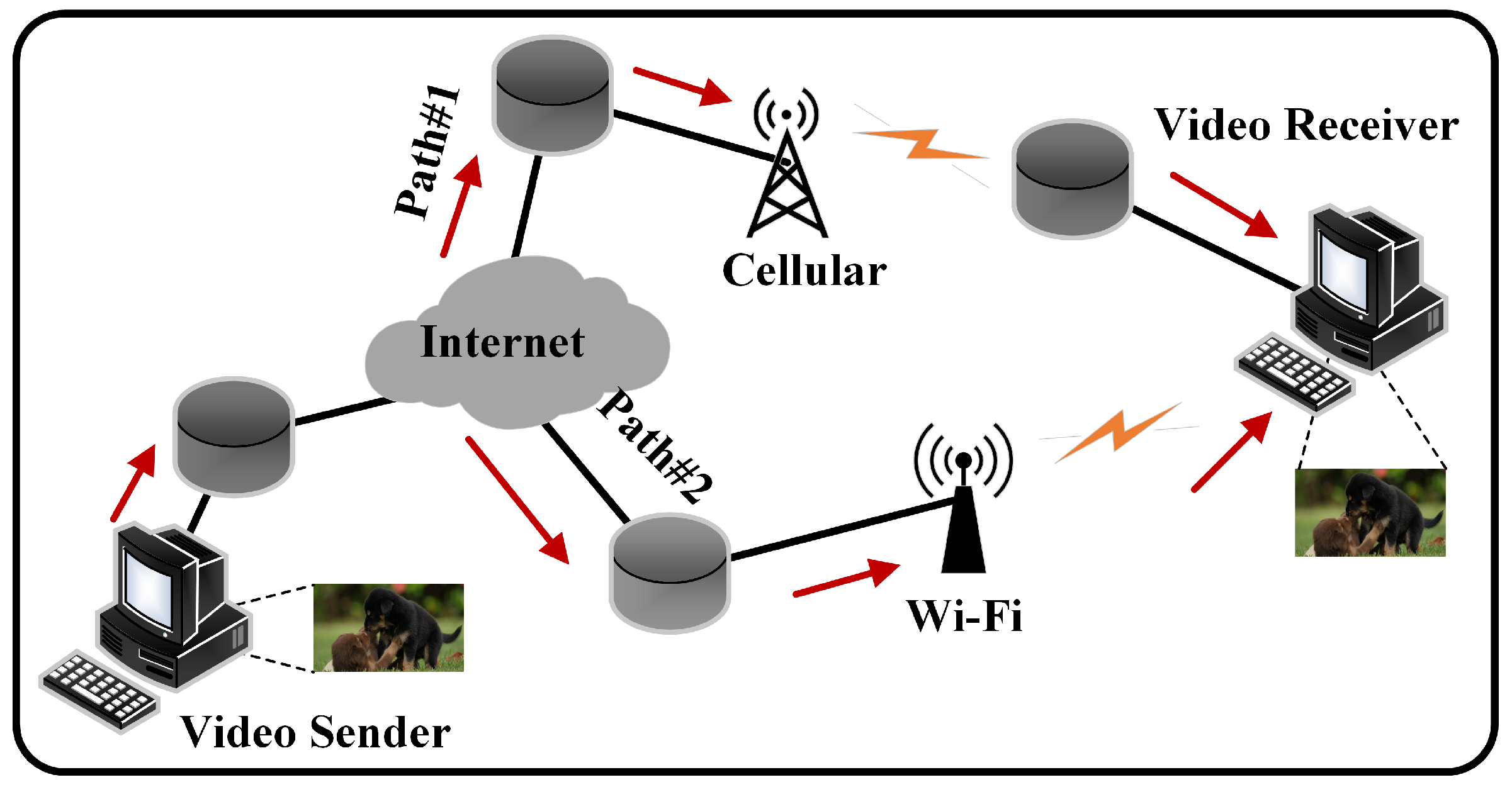
1. Introduction
- Proposing the LDMP-FEC algorithm to ensure video transmission quality in heterogeneous networks: This is achieved by using FEC encoding to protect transmitted data and adaptively deriving FEC redundancy based on the Gilbert model and continuous Markov chains to counteract packet loss in the channel.
- Modeling and deriving the expected arrival time intervals of data packets on each subflow based on current channel conditions: When the arrival time intervals of subflows do not overlap, data are sent through the shortest subflow. When intervals overlap, the scheduling algorithm switches to round-robin scheduling to ensure that data packets can arrive at the receiver end simultaneously within the shortest possible time for FEC decoding. This reduces waiting times and lowers the end-to-end latency of the video transmission.
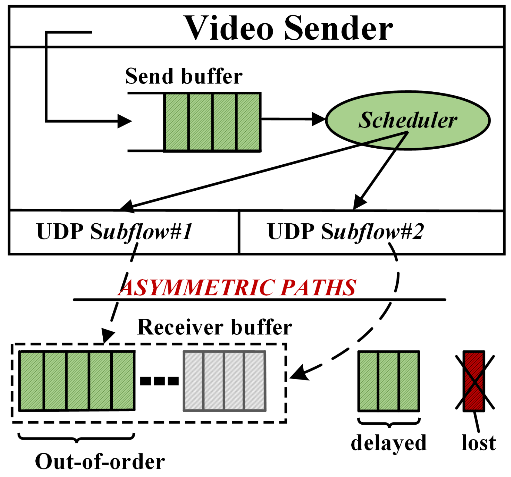
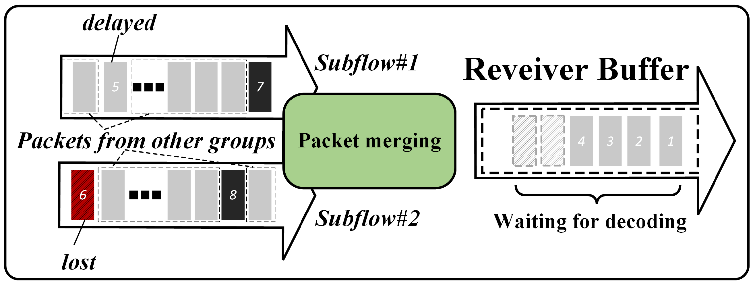
2. Causes of OFO-Packets and the FEC Mechanism
3. Low Delay Multipath FEC (LDMP-FEC) Scheme
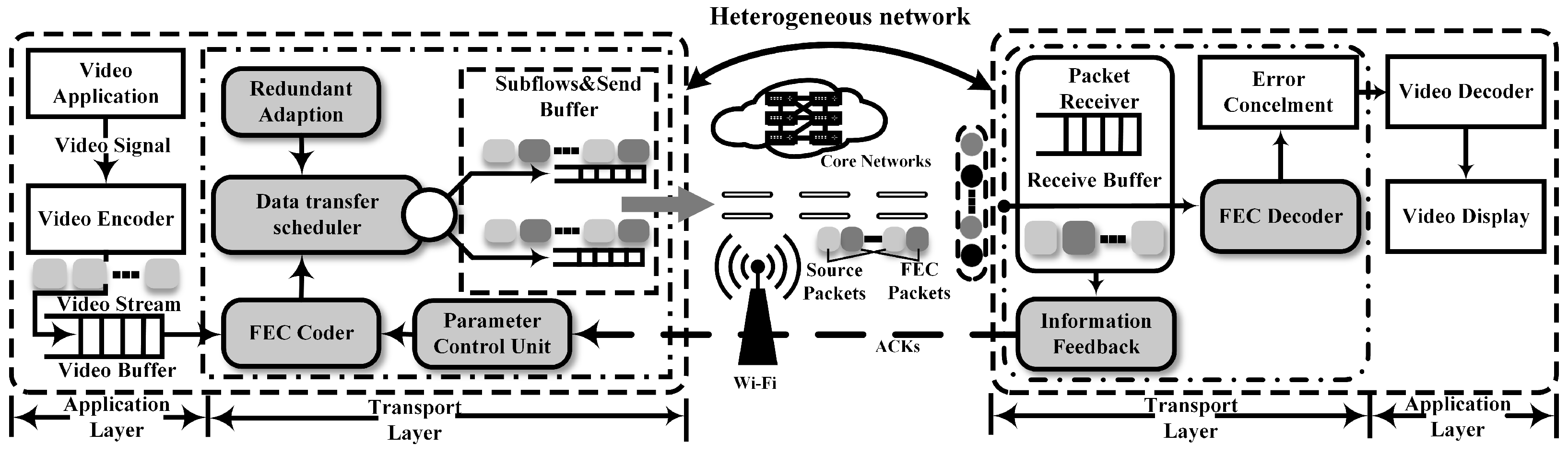
3.1. System Overview
3.2. FEC Encoding
3.3. FEC Adaptive Redundancy Algorithm
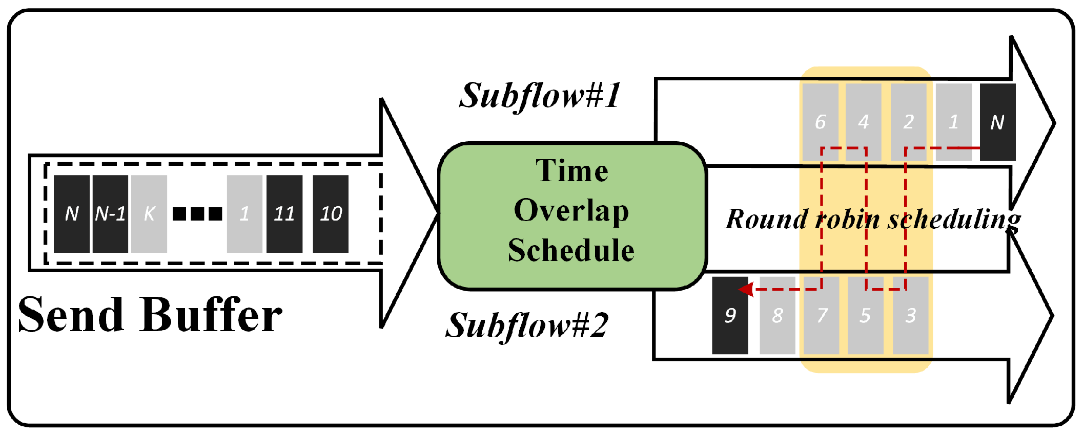
3.4. FEC Recovery Priority Scheduling (FEC-RPS) Algorithm
| Algorithm 1 FEC-RPS scheduling algorithm. |
Input: Subflow set S; Output: Selected subflows set;
|
3.5. System Overview
| Algorithm 2 LDMP-FEC algorithm. |
Input: videoDataBuffer, subflow set S Output: Selected subflow to send packets
|
4. Experiments and Results
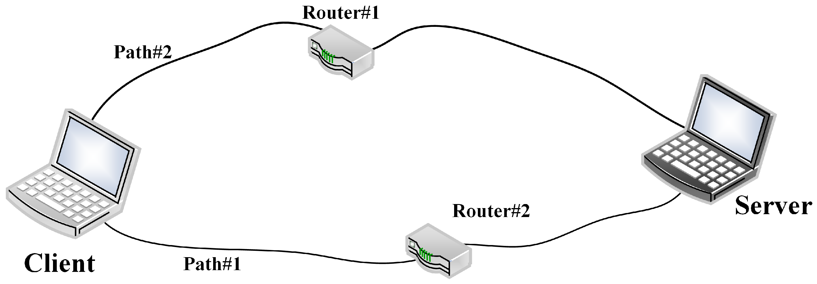
4.1. Experimental Setup
- MinRtt-FEC: Combines FEC for data protection with the MinRtt scheduling algorithm, with FEC redundancy () set to 10%.
- MinRtt: Employs the MinRtt scheduling algorithm without FEC encoding.
- Round-robin-FEC: Combines FEC for data protection with the round-robin scheduling algorithm, with FEC redundancy () set to 10%.
- Round-robin: Employs the round-robin scheduling algorithm without FEC encoding.
- FEC-RPS: Utilizes the FEC-RPS algorithm independently to evaluate its performance without FEC data protection.
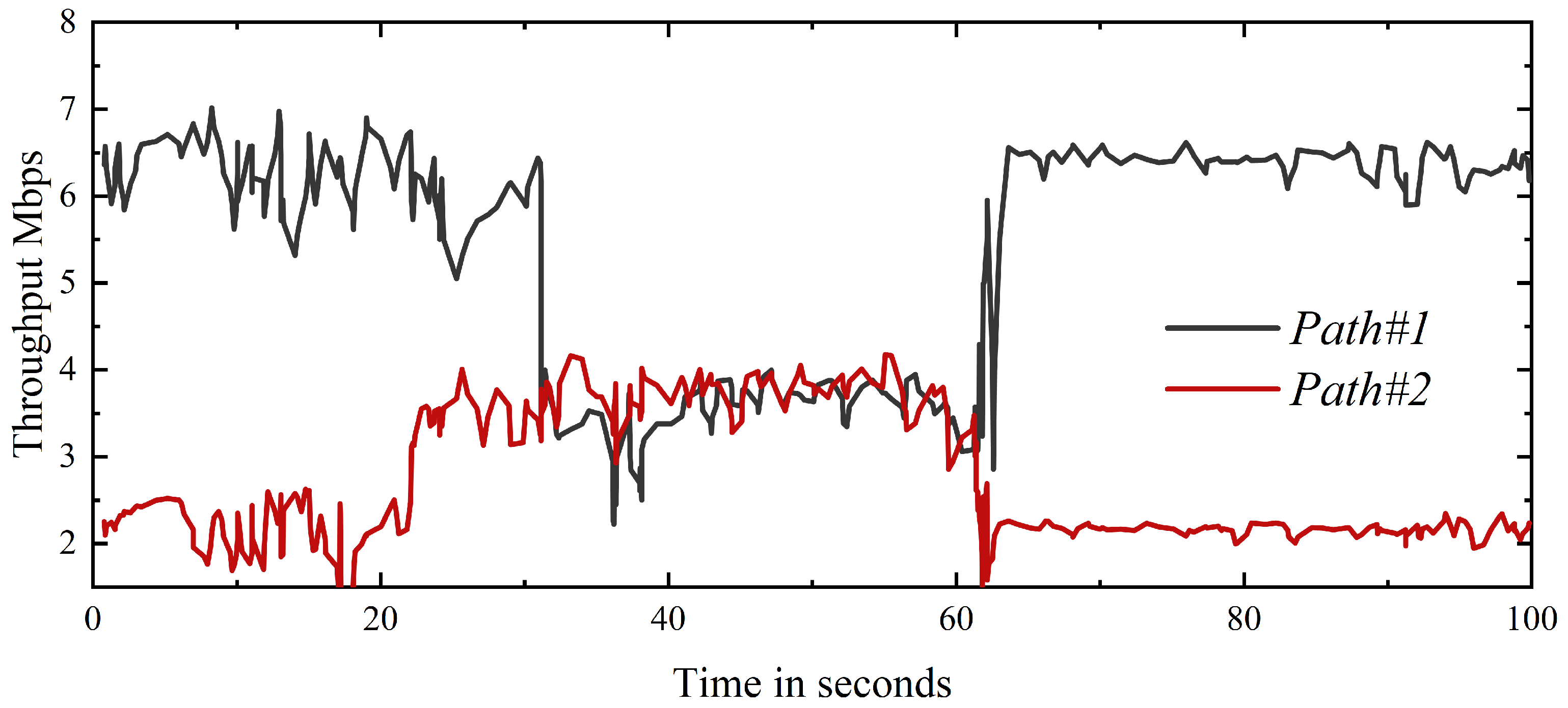
4.2. The Operation Status of Each Subflow
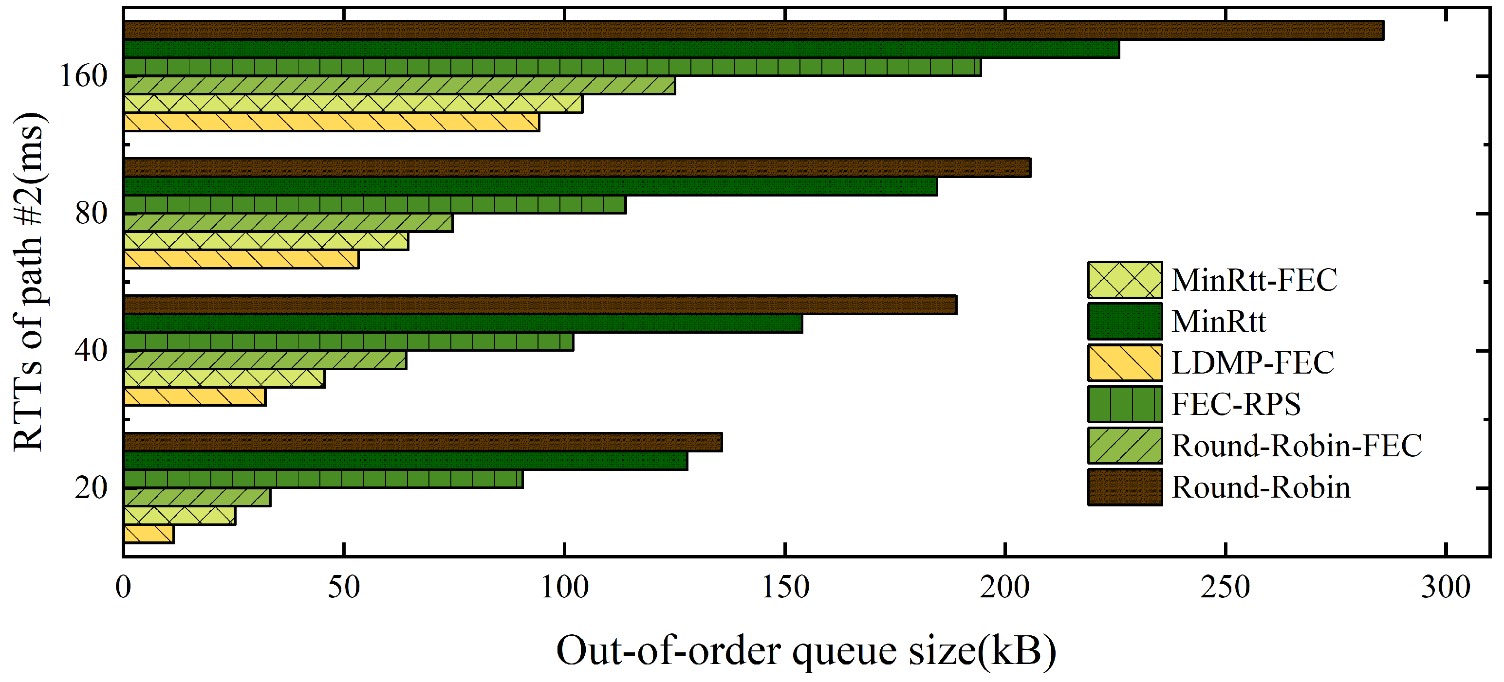
4.3. Out-of-Order Queue Size
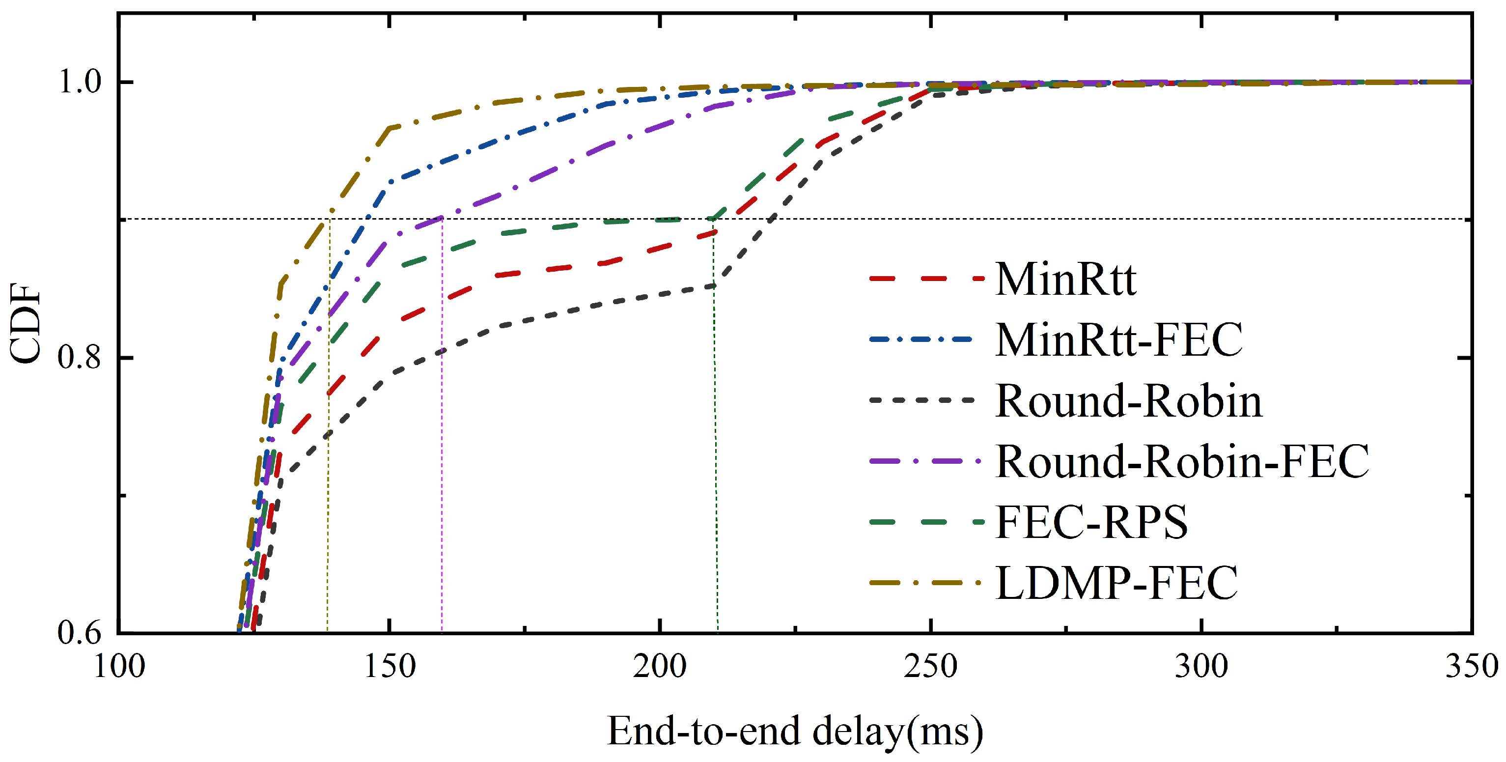
4.4. End-to-End Delay
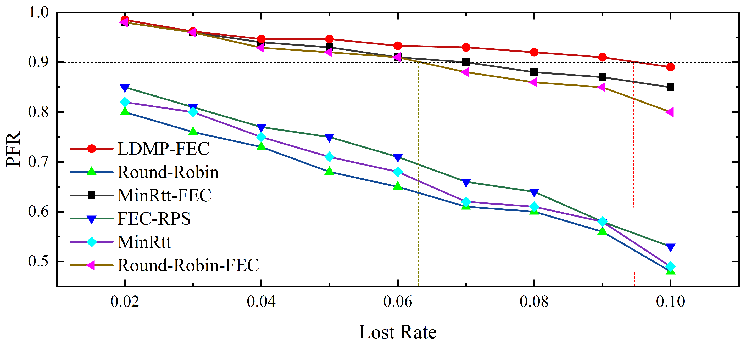
4.5. Playable Frame Rate
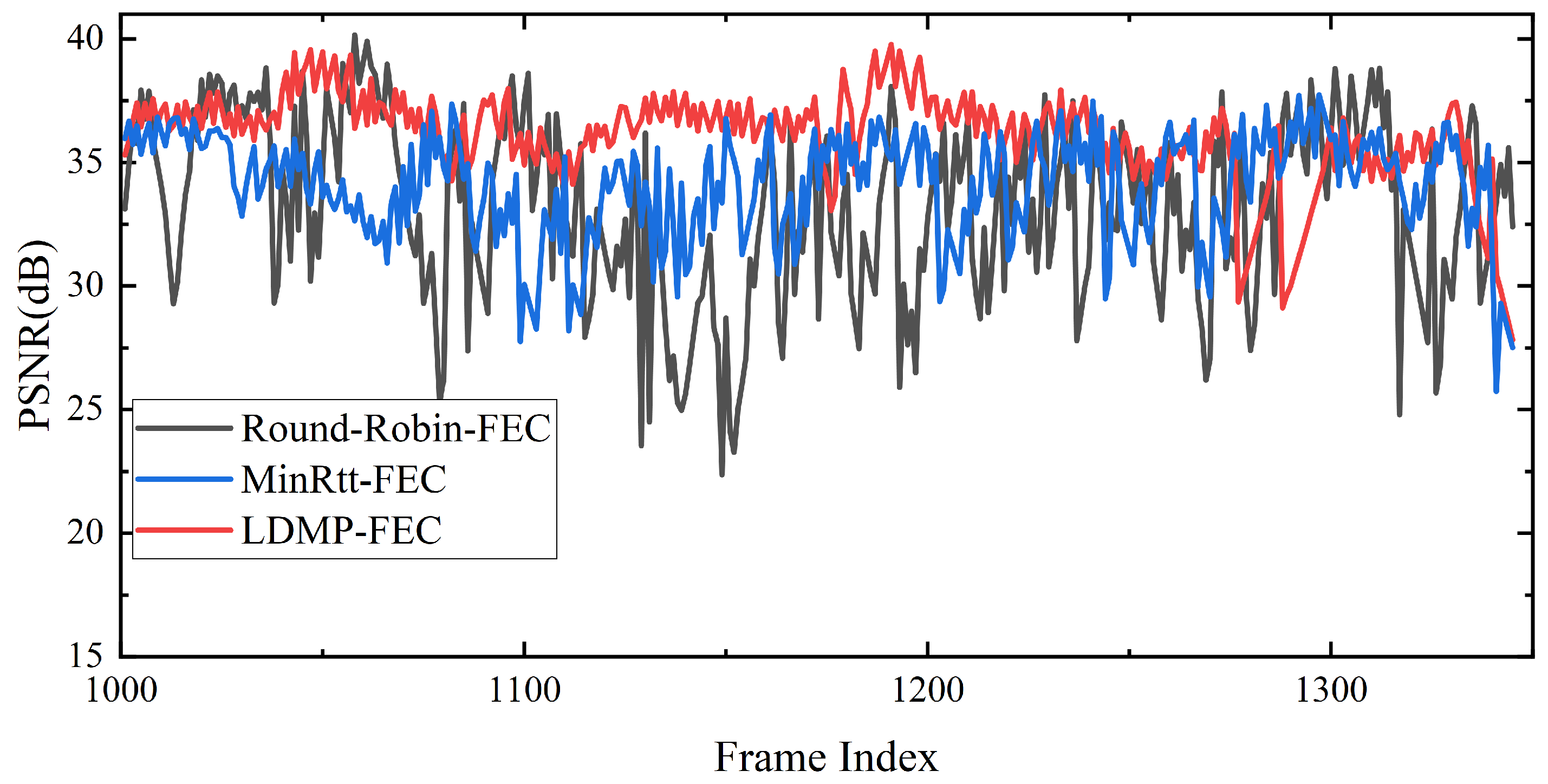
4.6. Peak Signal-to-Noise Ratio
5. Conclusions
Author Contributions
Funding
Institutional Review Board Statement
Informed Consent Statement
Data Availability Statement
Conflicts of Interest
References
- Dagiuklas, T.; Gatzounas, D.; Theofilatos, D.; Sisalem, D.; Rupp, S.; Velentzas, R.; Tafazolli, R.; Politis, C.; Grilli, S.; Kollias, V.; et al. Seamless multimedia services over all-IP based infrastructures: The EVOLUTE approach. In Proceedings of the IST Mobile and Wireless Telecommunications Summit, Thessaloniki, Greece, 16–19 June 2002. [Google Scholar]
- Tu, W. Resource-efficient seamless transitions for high-performance multi-hop UAV multicasting. Comput. Netw. 2022, 213, 109051. [Google Scholar] [CrossRef]
- Wu, J.; Yuen, C.; Cheng, B.; Wang, M.; Chen, J. Streaming High-Quality Mobile Video with Multipath TCP in Heterogeneous Wireless Networks. IEEE Trans. Mob. Comput. 2016, 15, 2345–2361. [Google Scholar] [CrossRef]
- Xing, Y.; Xue, K.; Zhang, Y.; Han, J.; Li, J.; Liu, J.; Li, R. A Low-Latency MPTCP Scheduler for Live Video Streaming in Mobile Networks. IEEE Trans. Wirel. Commun. 2021, 20, 7230–7242. [Google Scholar] [CrossRef]
- Han, B.; Ji, L.; Gopalakrishnan, V.; Qian, F. Adaptive Video Streaming over Preference-Aware Multipath. US Patent 10,348,796, 9 July 2019. [Google Scholar]
- Stockhammer, T. Dynamic adaptive streaming over HTTP—Standards and design principles. In Proceedings of the Second Annual ACM Conference on Multimedia Systems, San Jose, CA, USA, 23–25 February 2011; pp. 133–144. [Google Scholar]
- Xing, M.; Xiang, S.; Cai, L. A real-time adaptive algorithm for video streaming over multiple wireless access networks. IEEE J. Sel. Areas Commun. 2014, 32, 795–805. [Google Scholar] [CrossRef]
- Mao, H.; Netravali, R.; Alizadeh, M. Neural adaptive video streaming with pensieve. In Proceedings of the Conference of the ACM Special Interest Group on Data Communication, Los Angeles, CA, USA, 21–25 August 2017; pp. 197–210. [Google Scholar]
- Zhang, H.; Li, W.; Gao, S.; Wang, X.; Ye, B. ReLeS: A neural adaptive multipath scheduler based on deep reinforcement learning. In Proceedings of the IEEE INFOCOM 2019-IEEE Conference on Computer Communications, Paris, France, 29 April–2 May 2019; pp. 1648–1656. [Google Scholar]
- Guan, Y.; Zhang, Y.; Wang, B.; Bian, K.; Xiong, X.; Song, L. PERM: Neural adaptive video streaming with multi-path transmission. In Proceedings of the IEEE INFOCOM 2020-IEEE Conference on Computer Communications, Toronto, ON, Canada, 6–9 July 2020; pp. 1103–1112. [Google Scholar]
- Sepahi, A.; Cai, L.; Yang, W.; Pan, J. Meta-DAMS: Delay-Aware Multipath Scheduler using Hybrid Meta Reinforcement Learning. In Proceedings of the 2023 IEEE 98th Vehicular Technology Conference (VTC2023-Fall), Hong Kong, 10–13 October 2023; pp. 1–5. [Google Scholar]
- Zhang, Y.; Zhao, P.; Bian, K.; Liu, Y.; Song, L.; Li, X. DRL360: 360-degree video streaming with deep reinforcement learning. In Proceedings of the IEEE INFOCOM 2019-IEEE Conference on Computer Communications, Paris, France, 29 April–2 May 2019; pp. 1252–1260. [Google Scholar]
- Chu, T.T.; Labiod, M.A.; Tran, H.A.; Mellouk, A. GADaM: Generic Adaptive Deep-learning-based Multipath Scheduler Selector for Dynamic Heterogeneous Environment. In Proceedings of the ICC 2022—IEEE International Conference on Communications, Seoul, Republic of Korea, 16–20 May 2022; pp. 4908–4913. [Google Scholar] [CrossRef]
- Wu, H.; Alay, Ö.; Brunstrom, A.; Ferlin, S.; Caso, G. Peekaboo: Learning-based multipath scheduling for dynamic heterogeneous environments. IEEE J. Sel. Areas Commun. 2020, 38, 2295–2310. [Google Scholar] [CrossRef]
- Cui, Y.; Wang, L.; Wang, X.; Wang, H.; Wang, Y. FMTCP: A fountain code-based multipath transmission control protocol. IEEE/ACM Trans. Netw. 2014, 23, 465–478. [Google Scholar] [CrossRef]
- Li, M.; Lukyanenko, A.; Cui, Y. Network coding based multipath TCP. In Proceedings of the 2012 Proceedings IEEE INFOCOM Workshops, Orlando, FL, USA, 25–30 March 2012; pp. 25–30. [Google Scholar]
- Chiariotti, F.; Kucera, S.; Zanella, A.; Claussen, H. Analysis and design of a latency control protocol for multi-path data delivery with pre-defined QoS guarantees. IEEE/ACM Trans. Netw. 2019, 27, 1165–1178. [Google Scholar] [CrossRef]
- Ferlin, S.; Dreibholz, T.; Alay, Ö. Multi-path transport over heterogeneous wireless networks: Does it really pay off? In Proceedings of the 2014 IEEE Global Communications Conference, Austin, TX, USA, 8–12 December 2014; pp. 4807–4813. [Google Scholar]
- Ramachandran, A.; Kantarcioglu, D.M. Using Blockchain and smart contracts for secure data provenance management. arXiv 2017, arXiv:1709.10000. [Google Scholar]
- Polese, M.; Chiariotti, F.; Bonetto, E.; Rigotto, F.; Zanella, A.; Zorzi, M. A Survey on Recent Advances in Transport Layer Protocols. IEEE Commun. Surv. Tutorials 2019, 21, 3584–3608. [Google Scholar] [CrossRef]
- Wei, W.; Xue, K.; Han, J.; Wei, D.S.L.; Hong, P. Shared Bottleneck-Based Congestion Control and Packet Scheduling for Multipath TCP. IEEE/ACM Trans. Netw. 2020, 28, 653–666. [Google Scholar] [CrossRef]
- Lu, Y.P.; Lai, I.W.; Lee, C.H.; Chiueh, T.D. Low-Complexity Decoding for RaptorQ Codes Using a Recursive Matrix Inversion Formula. IEEE Wirel. Commun. Lett. 2014, 3, 217–220. [Google Scholar] [CrossRef]
- Zhu, X.; Agrawal, P.; Singh, J.P.; Alpcan, T.; Girod, B. Distributed Rate Allocation Policies for Multihomed Video Streaming Over Heterogeneous Access Networks. IEEE Trans. Multimed. 2009, 11, 752–764. [Google Scholar] [CrossRef]
- Zhou, L.; Wang, H.; Lian, S.; Zhang, Y.; Vasilakos, A.V.; Jing, W. Availability-Aware Multimedia Scheduling in Heterogeneous Wireless Networks. IEEE Trans. Veh. Technol. 2011, 60, 1161–1170. [Google Scholar] [CrossRef]

Disclaimer/Publisher’s Note: The statements, opinions and data contained in all publications are solely those of the individual author(s) and contributor(s) and not of MDPI and/or the editor(s). MDPI and/or the editor(s) disclaim responsibility for any injury to people or property resulting from any ideas, methods, instructions or products referred to in the content. |
© 2025 by the authors. Licensee MDPI, Basel, Switzerland. This article is an open access article distributed under the terms and conditions of the Creative Commons Attribution (CC BY) license (https://creativecommons.org/licenses/by/4.0/).
Share and Cite
Gao, T.; Chen, F.; Chen, P. LDMP-FEC: A Real-Time Low-Latency Scheduling Algorithm for Video Transmission in Heterogeneous Networks. Electronics 2025, 14, 563. https://doi.org/10.3390/electronics14030563
Gao T, Chen F, Chen P. LDMP-FEC: A Real-Time Low-Latency Scheduling Algorithm for Video Transmission in Heterogeneous Networks. Electronics. 2025; 14(3):563. https://doi.org/10.3390/electronics14030563
Chicago/Turabian StyleGao, Tingjin, Feng Chen, and Pingping Chen. 2025. "LDMP-FEC: A Real-Time Low-Latency Scheduling Algorithm for Video Transmission in Heterogeneous Networks" Electronics 14, no. 3: 563. https://doi.org/10.3390/electronics14030563
APA StyleGao, T., Chen, F., & Chen, P. (2025). LDMP-FEC: A Real-Time Low-Latency Scheduling Algorithm for Video Transmission in Heterogeneous Networks. Electronics, 14(3), 563. https://doi.org/10.3390/electronics14030563