4.1. Structure of the Coils in the Array
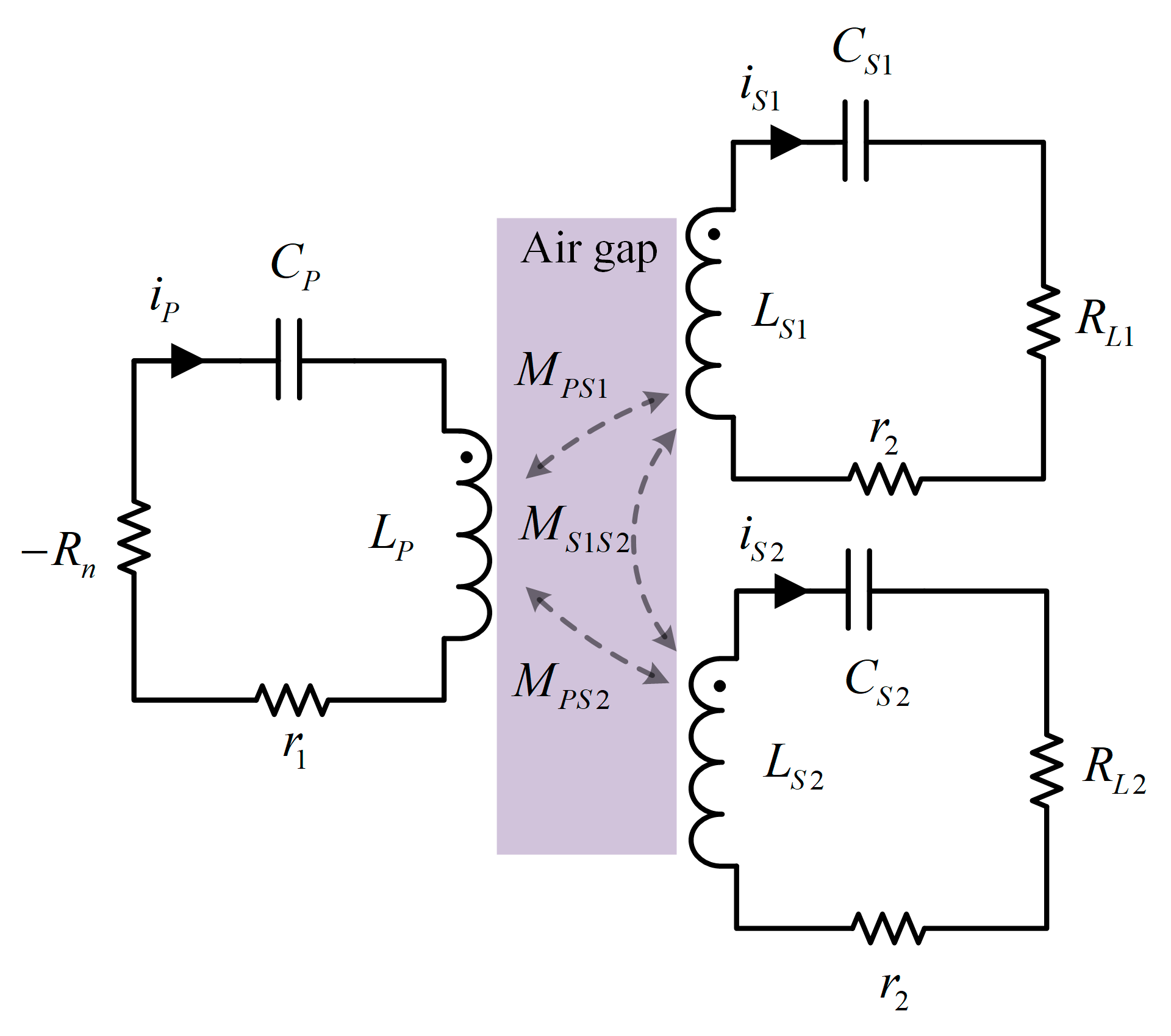
The near-field WPT essentially utilizes a Tx to direct the flow of the current through the wire structure to achieve the excitation of the electromagnetic field. Afterwards, the receiving device with closed windings interlinks with the magnetic inductance and inducts to obtain the current, thus realizing the conversion of electrical energy–magnetic energy–electrical in the WPT system. Therefore, the design of the coupler used for the conversion of electrical and magnetic energy directly determines the system’s offset resistance.
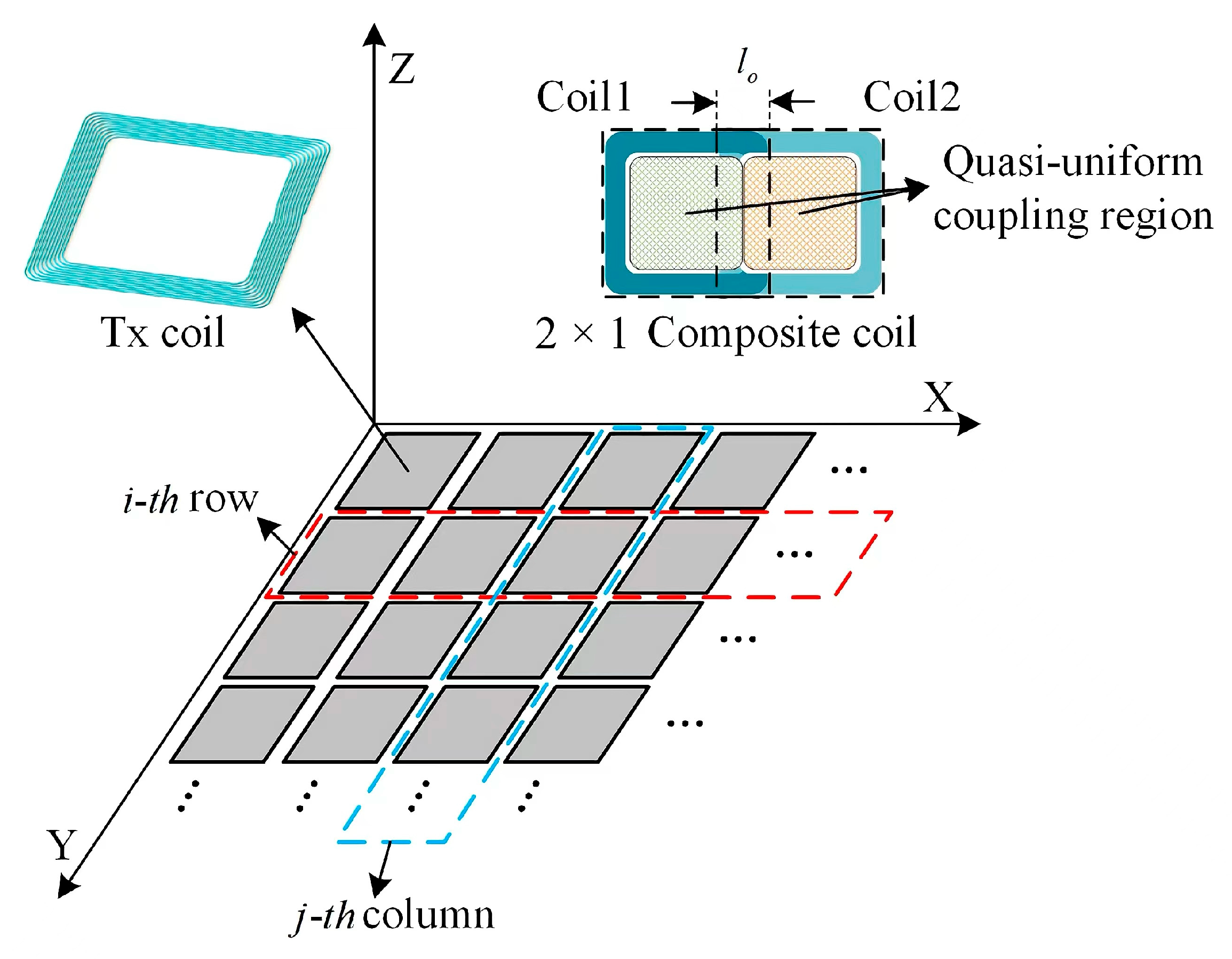
To ensure that Rx can receive sufficient power at any position, it is necessary for TA to have QC. The mutual inductance and coupling coefficient in this region are approximately constant, which can significantly reduce the interference caused by coil movement to the system. A few studies have investigated QC to improve the misalignment tolerance of the array, but the additional winding brings a complex structure, and it only supports independent Tx activation, which indicates that the size of the charging area cannot be flexibly configured. To this end, this study designs the Tx and Rx coils based on the PT system and follows some necessary design principles to ensure effectiveness and operability:
The coils should balance performance and cost. Excessive material consumption and design complexity are not conducive to the expansion of the array and the embedding of application objects.
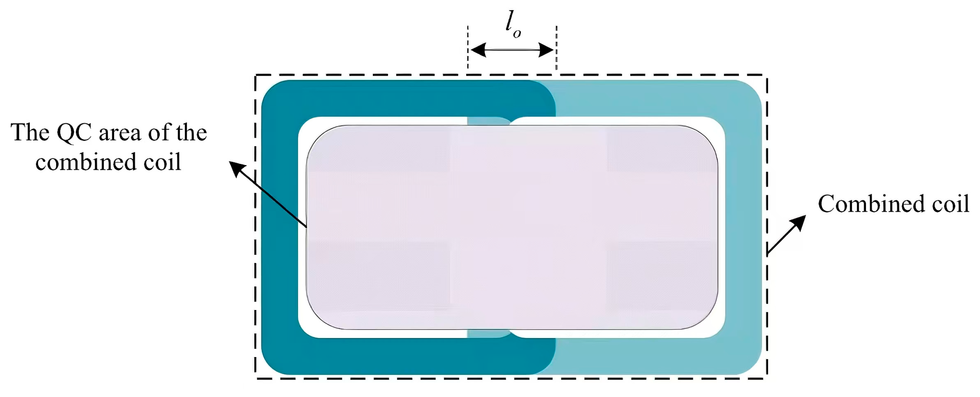
The 2 × 1 composite coils should still maintain QC to ensure stable power transfer for Rx in different configurations.
The cross-coupling between Tx should be estimated to achieve precise resonance compensation.
There should be a sufficient coupling coefficient between the compact Rx coil and Tx to meet the strong coupling requirements of the PT system.
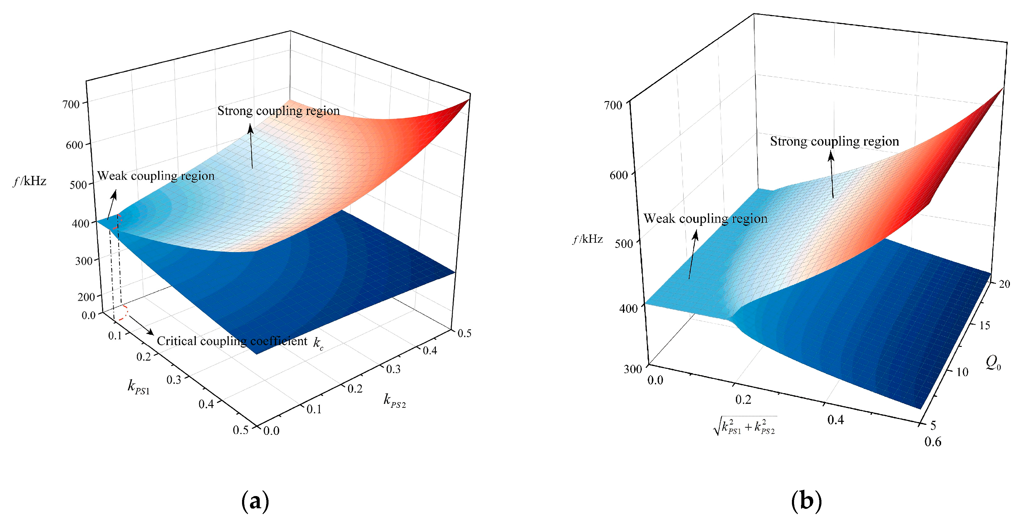
The previous mechanism study of the dual-load PT system shows that, for the system to work in the strong coupling region to achieve constant characteristic transmission, the coupling coefficients of the two Rx coils cannot be too low and must satisfy
, which essentially implicitly requires that the homogeneity of the magnetic field in the airgap should be high or else there exists a possibility for the flexibly moving Rx to move into the weak coupling region, which results in the destabilization of the system. For this reason, an array unit Tx with QC characteristics is proposed in this study.
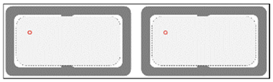
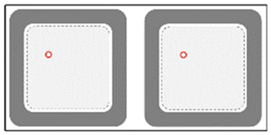
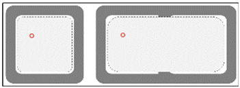
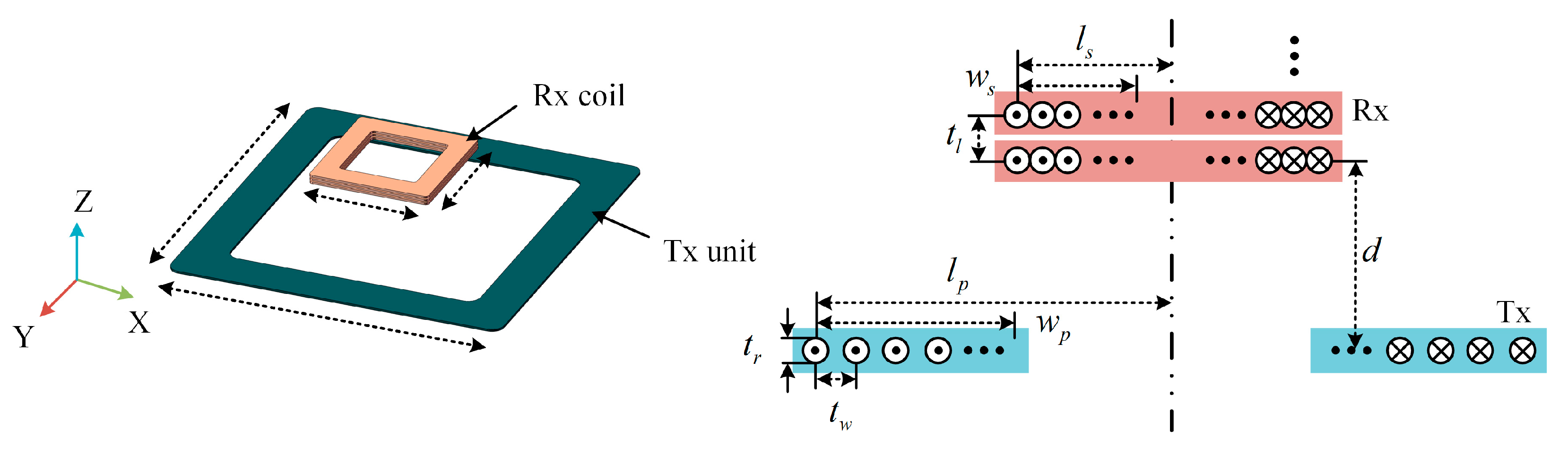
Figure 5 illustrates the structure of the Tx and the Rx, whereas the parameters are defined in
Table 3.
4.2. Tx Coil Design
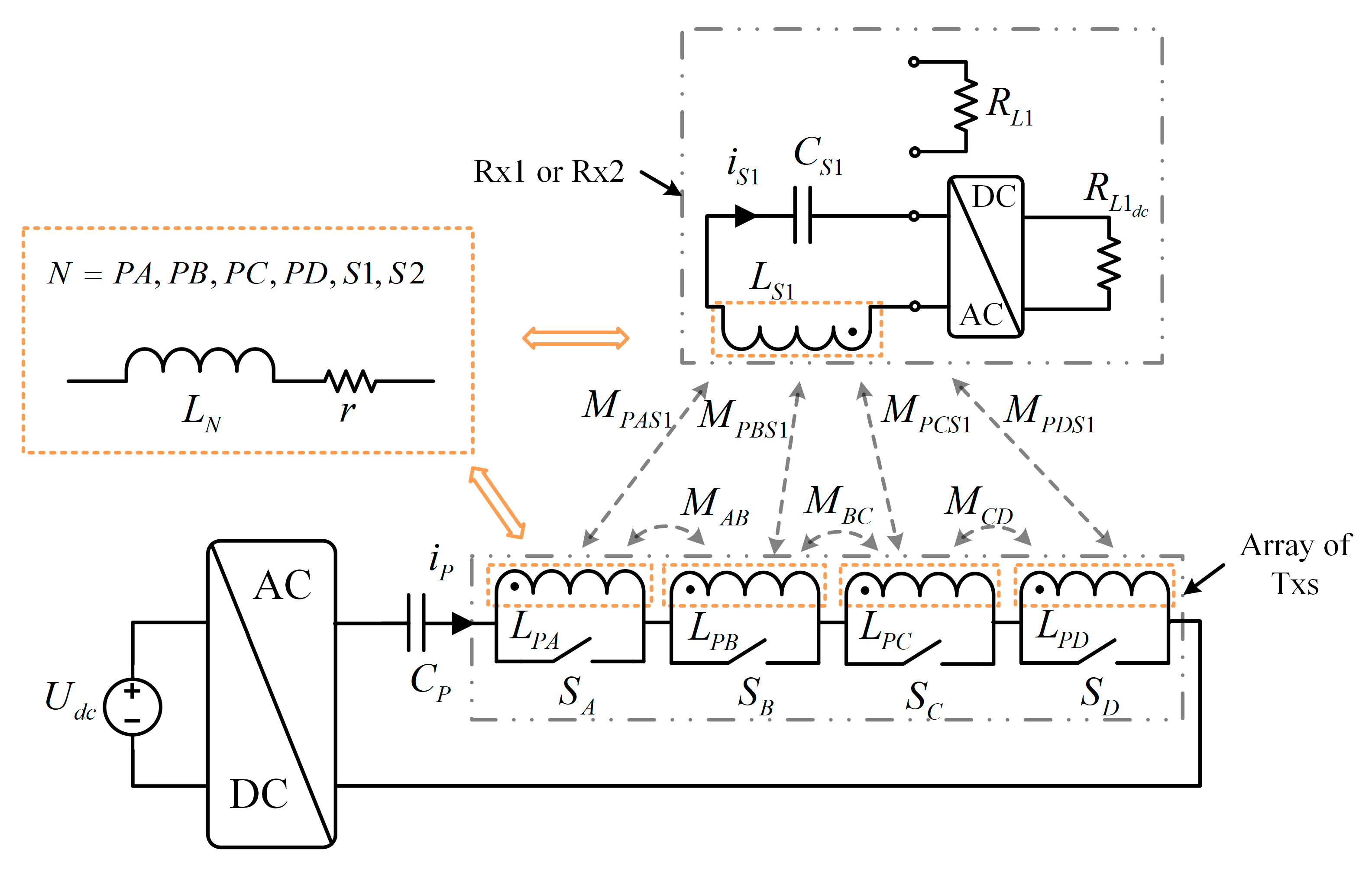
The Tx unit is formed by multi-turns of square windings, which is simple and easy to fabricate, and the symmetry of the structure ensures that the Tx has consistent coupling performances in the X and Y directions, while the Rx coils are formed by multilayers of square windings, which are compact and easy to be installed in various electronic products. In this study, the Tx and Rx coils are placed horizontally to simulate the common application scenarios of the WPT system. The transmission distance d of the system is set at 5 cm, which is used to ensure that the device has enough air gap height for mounting the housing, fixing the fixture, and necessary redundancy.
The structural parameters of the Tx coil will directly affect the magnitude and vector direction of the magnetic field in the air gap, and the parameters of the square coil that can have a significant effect on the magnetic field include the coil half-length
lP, the winding spacing
tw, and the number of turns of the winding
NP.
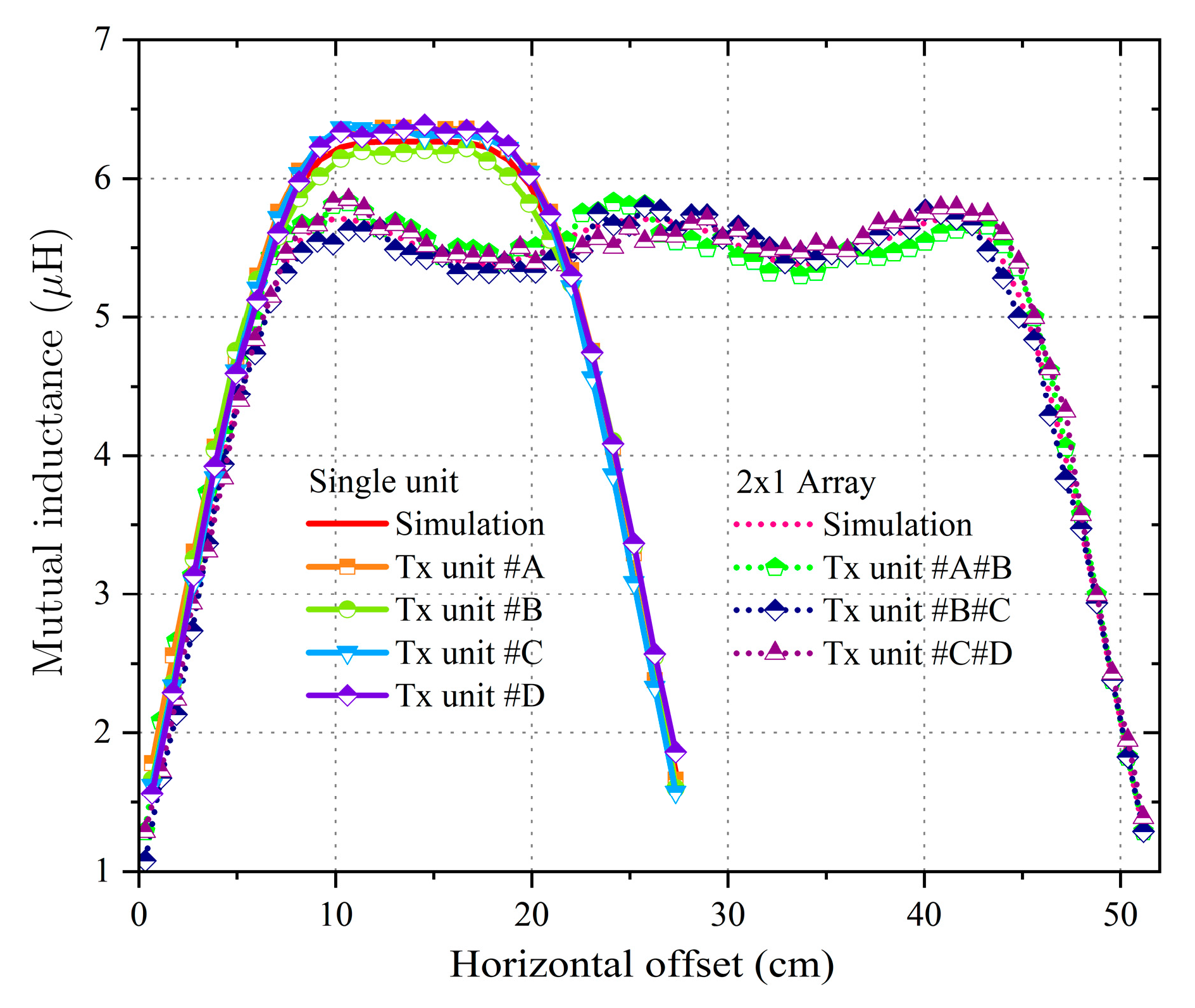
Figure 6a demonstrates the mutual inductance distribution curves with different X-axis offsets for fixed
,
and
when adjusting
tw. As the Tx coil exhibits uniform coupling characteristics in both the X and Y directions, scanning along the X-axis alone is adequate when the Rx is concentrically aligned with the Tx along the Y-axis. It can be observed that the mutual inductance distribution curve shrinks from wide to narrow when
tw varies from small to large. The width of the QC area at the center of Tx is the maximum when
. According to the flux calculation formula
, it can be seen that, for Rx and Tx placed in parallel, the effective flux receivable by Rx is the component perpendicular to the plane around which the coil is placed. Based on this,
Figure 6b shows the Z-axis component
BZ of the magnetic induction
B in the plane where Rx is located obtained using the Ansys analysis platform, and the simulation results are used to verify the uniformity of the magnetic field generated by the Tx unit. In the simulation, the loading current
is set, and from the results, it is easy to find that the Tx unit generates a
BZ approximate uniform region in the plane of Rx, i.e., the QC area, which is located in the inner part of the Tx winding. The Rx has approximately the same mutual inductance and
kPS at any position in this region, and this property effectively ensures that the two Rx coils satisfy the
, which ensures that the dual-loaded coils of the offset-resistant transmission system proposed in this paper have equal output power.
4.4. Multi-Objective Optimization of Array Structural Parameters
In order to ensure good QC of the TA for both a single Tx unit and neighboring Tx cooperating to form a 2 × 1 combined coil, multiple independent parameters contained in the coil structure need to be finely captured.
Some studies [
42,
43] adopted a general multi-objective optimization algorithm for coil design. However, Tx contains many parameters, and taking too many parameters as independent variables will result in a huge calculation cost. To address this problem principle, an analysis of the influence effect of the coil parameters is first conducted to gain prior knowledge. Based on this, the precise parameters of Tx can be determined by a simple and low-cost calculation procedure. The adjustable parameters of Tx include the maximum half-length
lpp (the optimized value of
lP), winding spacing
tw, winding width ratio
rd, and Tx overlap width
lo; the optimization goals include the QC area width
lQ, average mutual inductance in the QC area
MQ, coupling coefficient
kPS, and coil material consumption D (defined as the total winding length). In addition, the ratio of
lQ to Tx width, i.e.,
is self-defined as a measure of the size of the QC area provided by Tx. The effect of adjusting
tw and
rd on
,
MQ, and
kPS is shown in
Figure 9. Specifically,
Figure 9a shows that there is a significant correlation between
rd and
, and a too large
rd will shrink the QC area; also, changing
tw has little effect on
.
Figure 9b shows that adjusting
tw and
rd can affect
MQ, but the effect on
rd is more obvious. The PT system is sensitive to the
kC, and the coil needs to meet the condition
to ensure efficient power output.
Figure 9c demonstrates that increasing
rd can effectively improve the coupling coefficient
kPS, but the effect of
tw is not significant. This is because, when
rd is fixed, reducing
tw will increase the number of winding turns, and the mutual inductance will greatly increase the self-inductance of Tx, resulting in only a slight increase in
kPS. For example, at
, when
tw is reduced from 0.5cm to 0.25 cm,
kPS only slightly increases by 0.02, but this leads to about a doubling of the material consumption.
Table 4 summarizes the correlation between Tx parameters and performance indicators.
Table 4 shows that adjusting
rd and
tw has unrelated or non-conflicting effects on the coupling performance. However, there are optimization conflicts among multiple evaluation indicators, i.e., the optimization of one indicator will degrade other indicators. For example, increasing
rd can improve
kPS but reduce α
Q. According to this characteristic, this study proposes a segmented optimization method for Tx and placement distance, which reduces the computational complexity by reducing the number of variables for one-time optimization. The first step is to adjust
rd to ensure that Tx and composite coils have sufficient QC areas. Then, the second step is to optimize
tw to achieve the best correction between
D and
kPS. The model is specifically described as:
Step 1:
lo,
rd, and
lpp are adjusted to maximize
lQ.
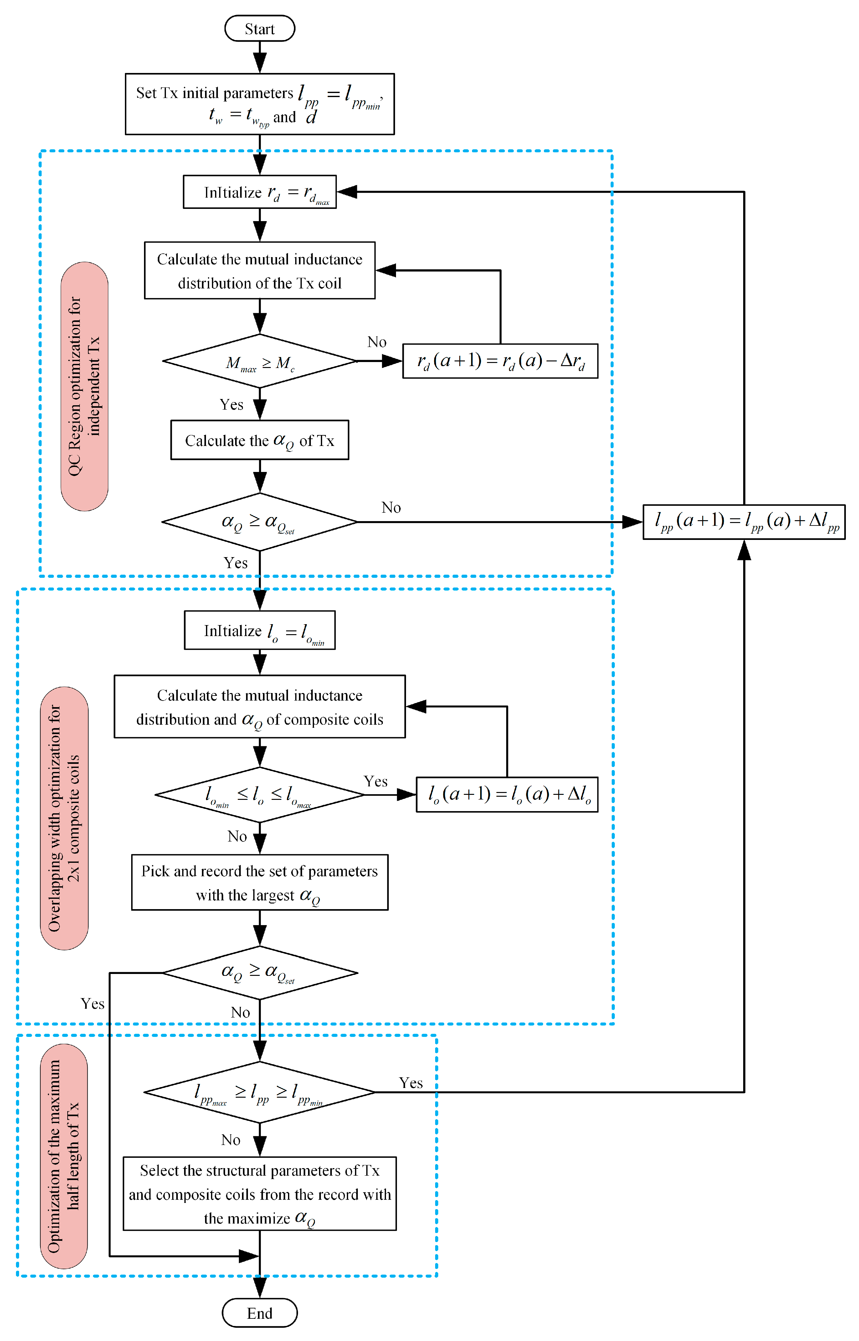
Figure 10 shows the optimization scheme of Step 1.
Since the influence of tw on αQ is negligible, tw is first initialized to a typical value, i.e., twyp = 5 mm. Step 1 consists of three parts: the first part is to adjust rd to optimize the lQ of Tx.
First,
rd is set to the maximum limit value of 0.9, and combined with finite element analysis (FEA), the distribution curve of the Rx offset and mutual inductance is obtained. If the maximum mutual inductance
Mmax in the curve satisfies
, then the
αQ of Tx is calculated; otherwise, the above procedure is repeated after a small amount of ∆
rd is subtracted from
rd. Afterward, it is determined whether
αQ is greater than the minimum limit
; if this condition is not satisfied,
lpp increases with ∆
lpp as the step size, and this part is re-executed; if this condition is satisfied, the second part is executed. The second part optimizes the overlapping width of the 2 × 1 composite coils to ensure stable QC after the adjacent Tx is activated simultaneously.
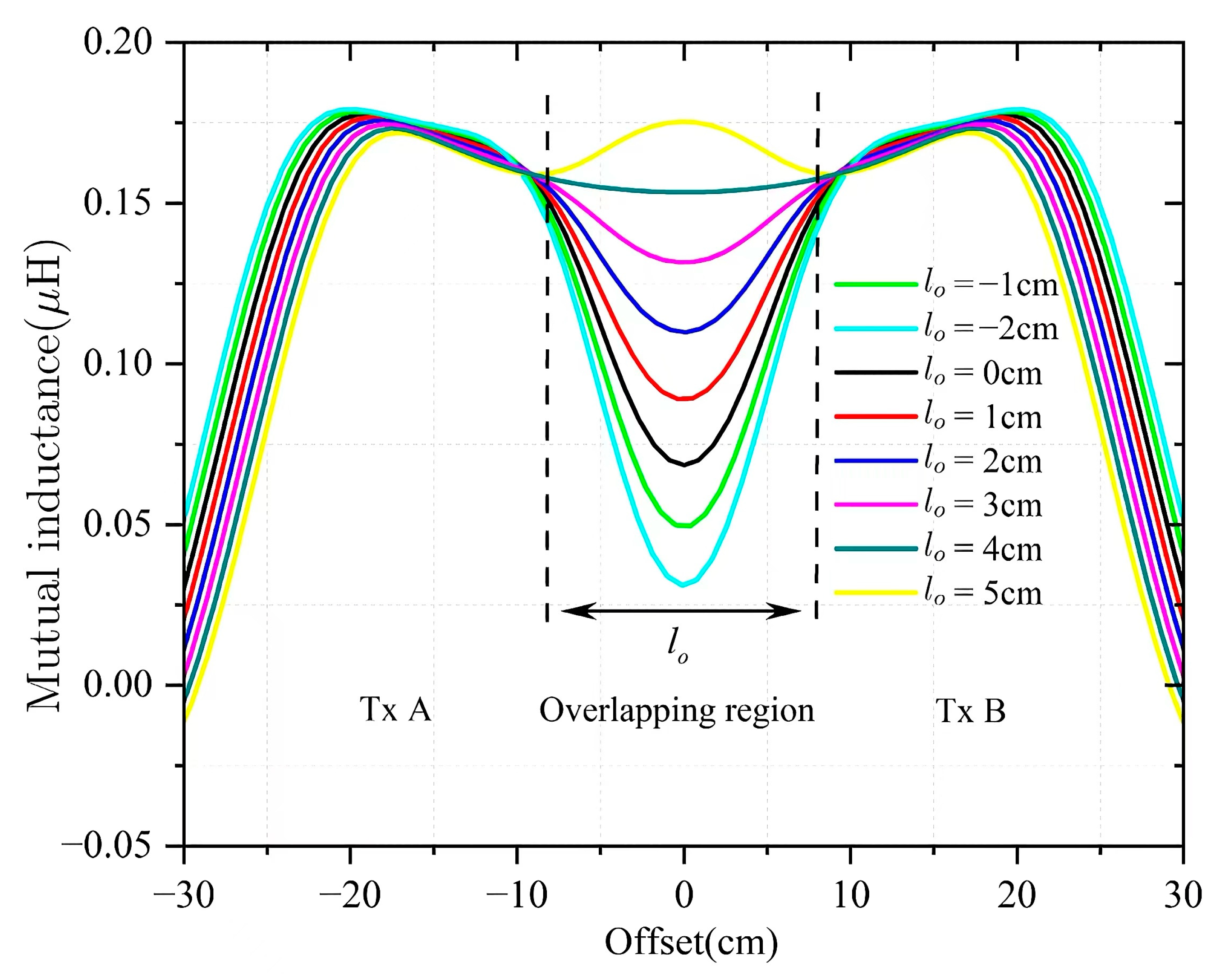
Figure 8 shows that
lo has a potential effective optimization range, and setting
lo too large or too small will lead to unstable mutual inductance in overlapping areas. According to the mutual inductance characteristic of Tx, the optimal range of
lo is limited to half of
lpp, i.e.,
and
. Then,
lo is increased iteratively with a step size of ∆
lo, and the
αQ of the composite coils obtained by each calculation is recorded. Upon completion of the program execution, the parameter settings corresponding to the maximum
αQ are identified as optimal for the current
lpp. Afterward, it is judged whether the program satisfies the exit condition
, and if so, the program is terminated in advance; otherwise, the third part is executed. After correcting
lpp in an increment of ∆
lpp, the program goes back to the beginning of the first part and runs again with the new parameter of
lpp.
If there is no qualified parameter after the running, the third part will select the result with the largest αQ under different values of lpp as the output of Step 1 according to the records. Considering the practicability and installation limitations of Tx, the maximum lpp of Tx is set in the range of 10 cm to 15 cm, i.e., lppmin = 10 cm and lppmax = 15 cm.
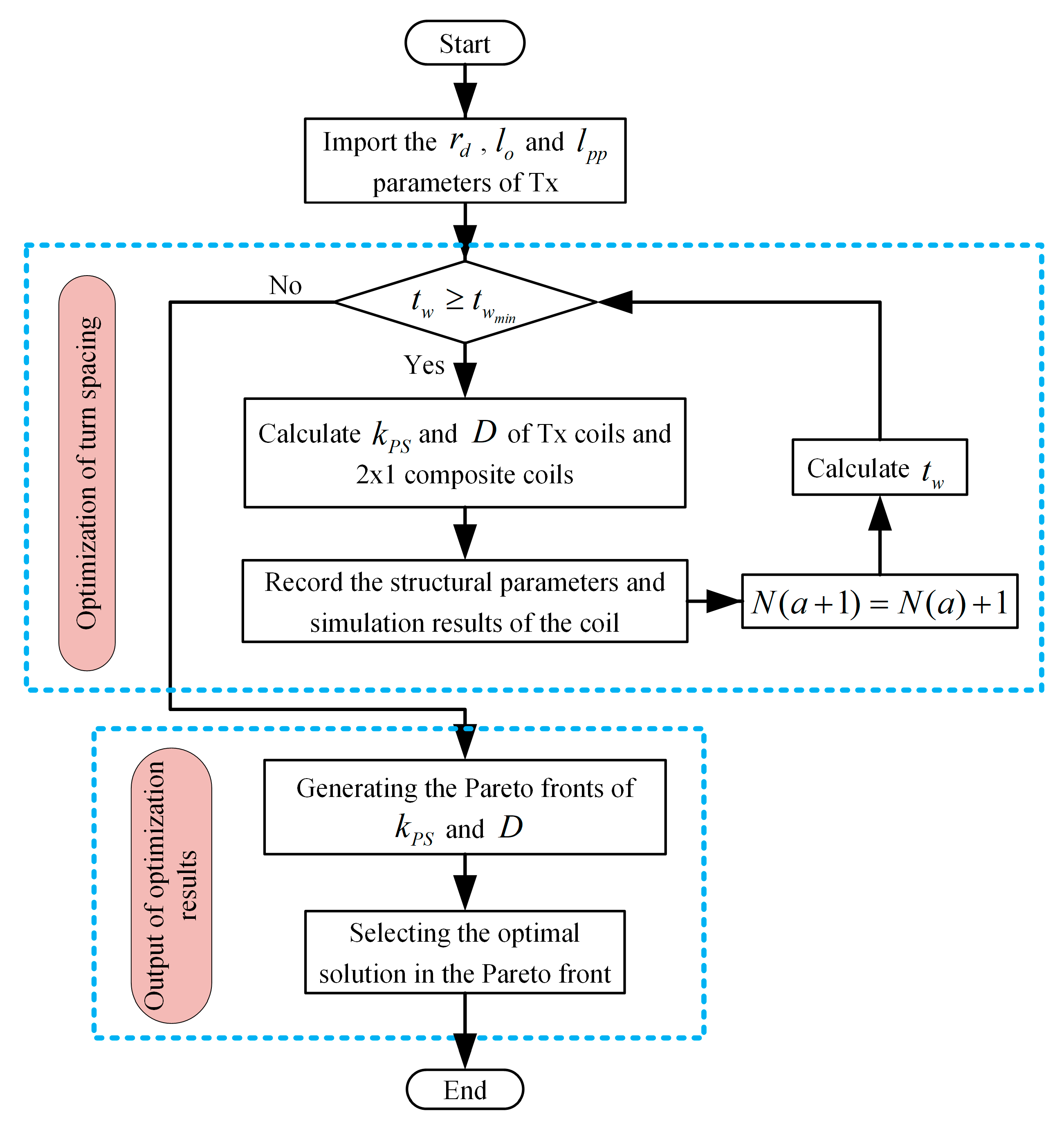
Step 2: The winding spacing
tw of Tx will be optimized under the balance of the coupling coefficient
kPS and material consumption
D to ensure that the coil has a balanced coupling coefficient and an acceptable cost. The optimization scheme of Step 2 is demonstrated in
Figure 11.
Step 2 first imports the output parameters of Step 1, including
lpp,
lo, and
rd of Tx. Since the composite coils have a larger self-inductance than the single Tx, its
kPS with Rx is lower, which is difficult to meet the strong coupling condition. Therefore, Step 2 will take the composite coils as the calculation object to simulate the limit condition. When the number of windings turns,
NP is initialized to 2, the program will calculate
kPS and
D cyclically when
NP changes, and these results and the current coil parameters after each calculation are recorded. This process is continued after adding one turn until the winding cannot ensure that
tw satisfies the current and power constraints
and the cycle ends. Subsequently, the program will generate a two-dimensional Pareto front [
43] according to the records, and based on this, the Pareto optimal solution is selected as the final output.
Based on the proposed optimization method, the final Tx coil parameters are listed in
Table 5.
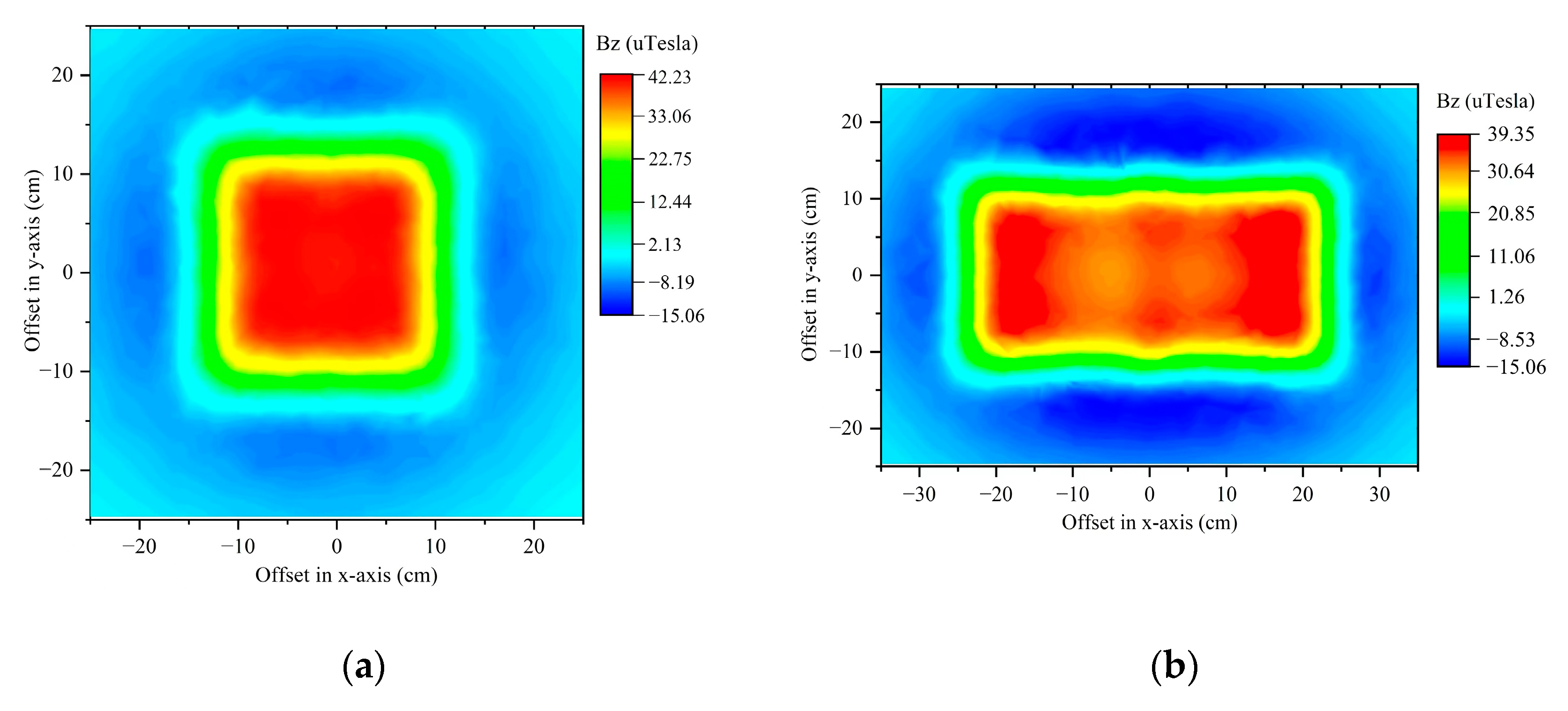
Figure 12 shows the magnetic field generated by the Tx and composite coils on the Rx plane obtained by FEA, which is employed to verify the effectiveness of the Tx design. As the effective magnetic flux received by the Rx is a component of the vertical winding,
Figure 12 illustrates the Z-axis component of the magnetic field strength. The loading current is set to 1A.
The results indicate that the Tx can provide a square QC area at the center of the winding and the composite coils can expand the QC area width to 41.6 cm, which leads to greater misalignment tolerance and a larger usable area. An Rx placed horizontally within this region has approximately constant magnetic flux reception.
The comparison with the distributed coil design in the previous literature is as follows: (i) The Tx in References [
32,
44] is internally configured with additional forward or reverse coupling windings, which results in a more complex structure and optimization process. The proposed Tx adopts a simple square structure that can be obtained by a low-cost procedure based on prior knowledge. (ii) Unlike the designs in [
26,
45] that only support a fixed number of Tx activations, considering the mutual inductance effect, in our design, adjacent Tx are allowed to be activated simultaneously to obtain a more flexible QC configuration, which allows TA to handle two random Rx. (iii) Different from the complex pitch layout adopted by the distributed coils in [
25,
46], the proposed planar array has concise expansion with bidirectional alignment, which contributes to high cost-effectiveness.
4.5. Rx Coil Design
The principal analysis indicates that the PT system can provide stable power transmission and high efficiency for two Rx coils in the strong coupling region. Therefore, the Rx should be designed to match the Tx to meet the necessary transmission conditions. The Rx should follow two design principles: (1) a high coil quality factor, which ensures a sufficiently low
kC and a larger movement tolerance, and (2) a compact size, although the large-sized Rx design has a larger surrounding area to capture more magnetic flux, and the excessive volume will affect its embedding into the application object. As the
RL and
r2 are fixed, increasing
Q0 will make the Rx coil have a greater self-inductance
LS, which has a negative effect on
. A decrease in
kC results in a corresponding decrease in
kPS. In an ideal magnetic field with a uniform Z-axis component, each turn placed horizontally coaxially around an
N-turn coil with an area of
S satisfies
where
is the ratio of the mutual inductance to the root self-inductance, and
,
, and
are constants. Equation (11) can be simplified to
, and
LS is not related to the value of
. This indicates that, in the Z-axis quasi-uniform magnetic field provided by TA, the Rx should adopt a design with approximately the same surrounding area of each turn winding to improve
redundancy. To this end, an Rx coil with a multilayer winding structure is proposed in this study, as shown in
Figure 5. Multilayer windings can arrange more windings in a limited space to increase mutual inductance. Also, this helps to reduce the width of the windings to make the situation close to the ideal one that the diameter of each turn is the same.
The values of
rm for different combinations of Rx layers and turns under unit vertical magnetic induction (
B = 1 web/m
2) are shown in
Table 6. Considering the limited installation space of Rx, the number of stacked layers is set to no more than 4, the number of turns of each layer ranges from 5 to 10, and the maximum radius of Rx
lS is fixed at 5 cm. Obviously, according to Equation (11) and
Table 6, a winding configured with three layers and eight turns per layer has maximized
rm, so it is chosen as the parameter setting of Rx. This design ensures that the winding width is less than 2 cm, and the overall height of the coil is less than 0.5 cm. The compact size makes it easy to install the R
X coil in various WPT applications.


 or
or