Article

Control Strategy for Asymmetric Faults on the Low-Frequency Side of a Sparse Modular Multilevel Converter

1
Hebei Provincial Key Laboratory of Distributed Energy Storage and Micro-Grid, North China Electric Power University, Baoding 071003, China
2
State Key Laboratory of Advanced Power Transmission Technology, China Electric Power Research Institute, Changping, Beijing 102209, China
3
Electric Power Research Institute of State Grid Liaoning Electric Power Co., Ltd., Shenyang 110000, China
*
Author to whom correspondence should be addressed.
Electronics 2025, 14(3), 426; https://doi.org/10.3390/electronics14030426
Submission received: 2 December 2024 / Revised: 14 January 2025 / Accepted: 20 January 2025 / Published: 22 January 2025

Abstract

:
Sparse modular multilevel converters (SMMCs) are a new type of lightweight high-voltage large-power AC/AC converter that significantly reduces the number of components compared to modular multilevel matrix converters (M3Cs). This study proposes a fault ride through a control strategy for SMMC to address the issues of arm energy imbalances and valve-side overvoltage, which occur during asymmetric faults on the low-frequency side. First, we establish models of the energy deviation of the arms under asymmetric short-circuit faults on the low-frequency side of SMMC. We also study the influence mechanism of the control strategies on the arm energy imbalance during faults. On this basis, an arm energy balancing strategy based on zero-sequence voltage injections combined with AC voltage control is proposed; this can achieve arm energy balance and suppress the negative sequence current and overvoltage of the SMMC. Finally, we construct a simulation model of an offshore wind power low-frequency transmission system based on the SMMC. The simulation results show that the proposed energy balance strategy can realize the stable operation of the low-frequency transmission system (LFTS) under asymmetric faults on the low-frequency side, that the maximum capacitor voltage deviation during the fault does not exceed 10% and that capacitor voltage returns to normal 0.25 s after the fault occurs.

1. Introduction

Low-frequency transmission systems (LFTSs) reduce the operational frequency of AC transmission lines from the standard 50 Hz to low frequencies such as 50/3 Hz or 20 Hz in order to shorten the electrical distance of AC transmission lines, thereby increasing their power transmission capacity. There are some potential application scenarios such as offshore wind power integration, large-scale renewable energy collection and transmission in weak grids [1,2,3,4].
High-voltage high-power AC/AC converters are the core components of low-frequency transmission technology [5]. As the current main AC/AC converter topology [6,7,8], modular multilevel matrix converters (M3Cs) have been trialed in flexible low-frequency transmission projects in Hangzhou and Taizhou, Zhejiang Province, China [4]. However, M3C stations still encounter footprint challenges due to the presence of a large number of sub-modules.
To address the lightweight issue of M3Cs, a series of topologies with different structures have been proposed, such as Y-type modular multilevel converters (Y-type MMCs) [9] and the hexagonal converter (Hexconverter) [10]. However, these converters still have a relatively large number of sub-modules. In contrast to these approaches, the sparse modular multilevel converter (SMMC) is a novel AC/AC converter based on sinusoidal half-wave frequency conversion, whereby the total number of components can be reduced to the same capacity. Notably, SMMC has 75% and 67% fewer capacitors and inductors respectively, resulting in lower costs compared to back-to-back modular multilevel converters (MMCs) and M3Cs. Moreover, SMMCs offer ZVS for more than half of their semiconductors, which are used for the voltage sharing of series-connected semiconductors [11].
In recent years, research on SMMCs has mainly focused on the basic principles, conventional power control, and arm energy balancing control [12,13,14]; meanwhile, the transient characteristics and fault ride-through (FRT) methods of SMMCs under LFTS faults have not been addressed. Most studies on the FRT control strategies of LFTS are based on the operational principles of M3C. Unlike the FRT control strategies for M3C-based LFTS [15,16], the arm energy balancing mechanism of SMMCs is more complex due to their half-wave multilevel modulation.
For generalized MMCs, voltage imbalance is a significant challenge. Over the past few years, many control methods have been proposed to achieve balance in the arm or submodule voltage, such as online vector calculation and constraint techniques [17] and simplified linear cluster voltage balancing controls based on zero-sequence voltage (ZSV) injections [18], etc. Regarding arm energy balancing, one study [19] presents a three-layer closed-loop control method based on conduction angles, ZVS, and nearest-level modulation (NLM), which achieves voltage balance across all submodules even under unbalanced conditions. The authors of [20] performed a comprehensive analysis of MMC, focusing on the voltage components applied to different arms to achieve internal energy balance by considering the degrees of freedom. Another study [21] proposes an independent energy balancing control method for each sub-converter of M3Cs, which balances the energy among the three arms by injecting only output-frequency circulating currents.
When an asymmetric fault occurs in the grid, there is usually a three-phase power imbalance in the converter. To effectively manage the interphase power distribution in converters, standard instantaneous power theory (IPT) is typically used to determine the reference values of active and reactive power, which, in turn, are used to calculate the required current and voltage references. The authors of [22] derived the analytical expression of the instantaneous ZSV and employed this theory to address interphase power imbalance issues in a small-scale Cascaded H-Bridge (CHB) system. Meanwhile, [23] introduces a ZSV injection method that can provide instantaneous ZSV references using steady-state ABC frame variables without the need for numerical iteration or phase-locked loops.
Under the conditions of asymmetric faults, SMMCs not only suffer from interphase power imbalances but also need to deal with the internal arm energy balance of the single phase. When an asymmetric fault occurs on the low-frequency side, the low-frequency terminal voltage introduces asymmetric characteristics if the conventional constant AC voltage control is adopted. The magnitude ratio of AC terminal voltages on both sides of the SMMC deviate from the arm energy balance constraint, and the degrees of deviation among the three phases are different, which poses a challenge to the stable operation of the LFTS. Moreover, during the faults, the overvoltage issue is also coupled with the arm energy unbalancing of the SMMC. Conventional instantaneous power theory cannot by itself address the energy balance issue. Based on the arm energy balance mechanism, a comprehensive consideration of overvoltage suppression, fault current suppression, and energy balance control strategies is needed.
This study investigates the transient characteristics and FRT strategies of the SMMC under the conditions of asymmetric faults on the low-frequency side for a windfarm-connected LFTS. The main contributions of this study are as follows:
  • The mathematical models of SMMC arm energy under the conditions of low-frequency-side asymmetric faults are established to analyze the arm energy imbalance phenomenon in the converter using an existing energy balancing control strategy.
  • The constraint conditions of the arm energy balance with a zero-sequence voltage injection are derived under the condition of asymmetric faults, and an energy balance control method based on the zero-sequence voltage injection is proposed.
  • Combining zero-sequence voltage injections and constant power factor angle AC voltage control, a FRT strategy for the SMMC-based LFTS is proposed, which effectively maintains the arm energy balance in the converter while suppressing the negative sequence current and overvoltage.
At the end of this study, based on the proposed control strategy, we perform a simulation for low-frequency transmission systems that connect offshore windfarms and the grid, in order to verify the effectiveness of the proposed control strategy.

2. SMMC Model and Control Strategy

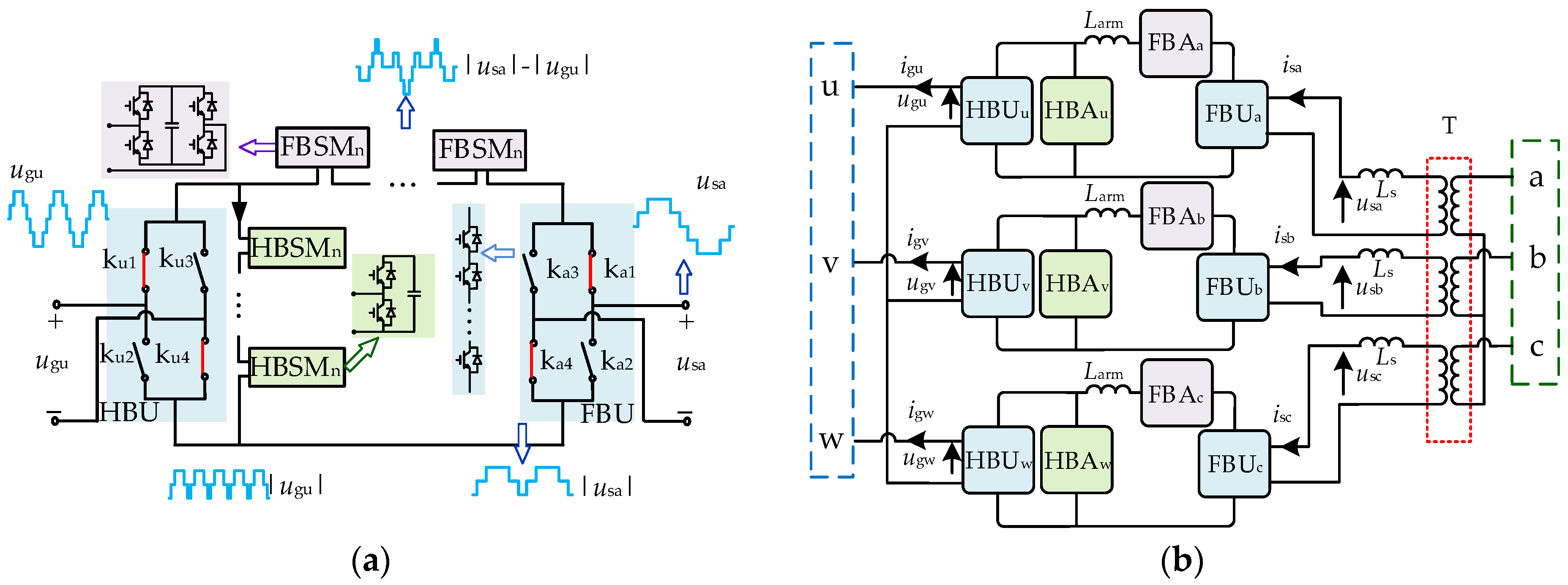
2.1. SMMC Topology and Operating Principles

The SMMC topology is shown in Figure 1; it connects two AC systems with different frequencies and magnitudes. The low-frequency terminal voltage is denoted as usa, usb, and usc and the current as isa, isb, and isc. The line-frequency (grid-side) terminal voltage is denoted as ugu, ugv, and ugw and the current as igu, igv, and igw. Larm represents the arm inductance, and Ls is the equivalent inductance on the low-frequency side. For SMMC, three single-phase two-winding transformers are needed to achieve interphase isolation.
Each single-phase SMMC consists of two low-frequency unfolders (HBU and FBU), a cascaded half-bridge submodule arm (HBA), and a cascaded full-bridge submodule arm (FBA). In Figure 1a, ku1~ku4 and ka1~ka4 are the switches for the unfolders on both sides, which are four strings of series-connected semiconductor devices.
The voltages and currents on both sides can be expressed as:
u gu = U gm sin ( ω g t ) i gu = I gm sin ( ω g t φ g ) u sa = U sm sin ( ω s t + θ f ) i sa = I sm sin ( ω s t + θ f φ s )
where Ugm and Igm and Usm and Ism are the magnitudes of the voltage and current on the corresponding side, respectively; φg and φs are the power factor angles; ωg and ωs are the angular frequencies; and θf is the initial phase difference between the voltages of both sides.
In Figure 1a, the typical waveforms are also given before and after each conversion. The HBA generates the line-frequency half-wave multilevel voltage |ugu|, and the FBA modulates the difference voltage |usa|−|ugu|, which produces the low-frequency half-wave multilevel voltage |usa|. The half-wave multilevel voltages |ugu| and |usa| on both sides are unfolded by HBU and FBU to obtain the line-frequency and low-frequency sinusoidal multilevel voltages ugu and usa. The switching functions of the unfolders can be defined as follows:
S u =   1 , u gu 0 1 , u gu < 0 ,   S a =   1 , u sa 0 1 , u sa < 0
According to Figure 1 and Equations (1) and (2), the voltages of HBA and FBA, uHu and uFa, and the arm currents iHu and iFa can be expressed as follows:
u Hu = S u u gu i Hu = S a i sa S u i gu u Fa = S a u sa S u u gu i Fa = S a i sa
As shown in Figure 2, the input power pa of phase a is transmitted to the intermediate power pm through FBAa, and then, pm provides the power of HBAu, pHu, and the output power of phase u, pu. All the above power can be expressed as follows:
p m = u Hu i Fa = S u S a u gu i sa p u = u gu i gu p a = u sa i sa
Based on Equations (2)–(4), pHu and the power of FBAa, pFa are obtained as follows:
p Hu = p m p u p Fa = p a p m
According to Equation (5), to achieve arm energy balance, it is necessary to ensure that the arm average PHu and PFa values are zero over the fluctuation period T of the submodule capacitor energy within the arms. Therefore, the energy balance constraint can be written as follows:
P a = P u = P m
where Pa, Pu, and Pm represent the average values of pa, pu, and pm, respectively. Pa and Pu can be expressed as:
P a = 1 2 U sm I sm cos φ s P u = 1 2 U gm I gm cos φ g
Based on Equations (4), (6), and (7), the energy balance constraint can be further derived as follows:
U sm U gm = 2 T S a sin ( ω s t φ s + θ f ) sin ( ω g t ) d t T cos φ s
Under the arm energy balance constraint, Equation (8) shows that the amplitude ratio of the SMMC AC voltage is related to the frequencies of the AC systems on both sides, the power factor, and the initial phase difference. There is no analytical solution for the voltage amplitude ratio, but numerical analysis shows that, for LFTS with a line frequency of 50 Hz and a low frequency of 20 Hz, Usm/Ugm is approximately a fixed value of 0.81 [12] when arm energy balance is achieved. When Usm/Ugm deviates from 0.81, conventional controls cannot maintain the arm energy balance, and energy balance controls must be employed.

2.2. Basic Control of SMMC Normal Operations

The topology of the offshore wind power low-frequency transmission system is shown in Figure 3. UL represents the equivalent inductance voltage on the low-frequency side, and ust indicates the low-frequency-transformer converter-side voltage. Uss and iss are the transformer low-frequency line-side voltage and current, respectively. Usw and Vwg represent the low-frequency cable-side voltage of the windfarm and the wind power collection-side voltage, respectively. Lw is the equivalent inductance of the windfarm. To simplify the analysis, the windfarm is equated with a current-controlled voltage source converter (VSC). The windfarm output is 20 Hz AC power, which is transmitted through the submarine cable to the low-frequency side of the frequency conversion station; then, it is transformed into line-frequency AC power using an SMMC and integrated into the onshore grid.
To support the voltage of the offshore windfarm, an AC voltage control is applied on the low-frequency side of SMMC. The authors of [12] introduce a third harmonic voltage injection on the low-frequency side of SMMC as an additional control to achieve arm energy balance when the converter operates over a wide voltage range.
The third harmonic voltage can be expressed as:
u 3 = k 3 U sm sin ( 3 ω s t + β 3 )
The value of k3 is determined by the control of the total submodule capacitor voltage of the three-phase full-bridge arm:
k 3 = ( u CN u CF ) ( k p 1 + k i 1 s )
where uCN is the rated value of the sub-module capacitor voltage, uCF is the average value of the full-bridge arm sub-module capacitor voltage, and kp1 and ki1 are the proportional and integral coefficients of the full-bridge arm energy balance PI controller.
Additionally, to achieve balance in the capacitor voltages of the sub-modules within the arm, both the half-bridge and full-bridge arms use a nearest-level modulation strategy based on a capacitor voltage-sorting algorithm. The basic control strategy based on a third harmonic injection for SMMCs under normal operational conditions is shown in Figure 4. In the figure, Lg represents the equivalent grid-connected inductor on the line frequency side. Ugd, ugq, igd, and igq represent the d and q axis components of ug and ig, respectively. Issd and issq represent the d and q axis components of iss, respectively.

3. Analysis of the Energy Imbalance Mechanism in SMMC Arms

Single-phase grounding faults are the most common type of fault in the grid [24]. Two phase-to-phase short circuit faults constitute another common type of fault, usually occurring between two phases. Although not as common as single-phase grounding faults, they also have a high probability of occurrence. These two kinds of fault are considered in this section.

3.1. Analysis of the Arm Energy Imbalance Mechanism Under a Single-Phase Short-Circuit Fault

Considering that submarine cable faults are mostly permanent faults and FRT cannot be achieved, in the following analysis, it is assumed that temporary faults occur on the low-frequency side of the SMMC. During a single-phase ground short-circuit fault, the onshore converter station generally adopts a negative sequence current suppression strategy to reduce the negative sequence current to zero. Considering the zero-sequence current at the fault location is very small, we can assume that the zero-sequence voltage at the fault location is also zero. Taking phase a as an example, the voltage sequence components on the cable side of the transformer have the following relationships [25]:
u ssa + + u ssa = 0 u ssa 0 = 0
where ussa+, ussa−, and ussa0 represent the positive sequence, negative sequence, and zero-sequence components of ussa, respectively.
The positive and negative sequence components of uss can be expressed as:
u ssa +   u ssa u ssb +   u ssb u ssc +   u ssc = U fm sin ( ω s t ) sin ( ω s t ) sin ( ω s t 2 π 3 )   sin ( ω s t π 3 ) sin ( ω s t + 2 π 3 )   sin ( ω s t + π 3 )
Since the transformer adopts a Y0/Δ connection, the positive sequence voltage of ust leads uss+ by π/6, and the negative sequence voltage of ust lags uss− by π/6. Therefore, the phase voltage of ust can be further expressed as:
u sta u stb u stc = U fm sin ( ω s t + π 6 ) + sin ( ω s t + 5 π 6 ) sin ( ω s t π 2 ) + sin ( ω s t π 2 ) sin ( ω s t + 5 π 6 ) + sin ( ω s t + π 6 )
The phase current is without negative and zero-sequence components can be expressed as:
i sa i sb i sc = I fm sin ( ω s t φ f + π 6 ) sin ( ω s t φ f 2 π 3 + π 6 ) sin ( ω s t φ f + 2 π 3 + π 6 )
where Ifm is the amplitude of the fault current and φf is the power factor angle on the low-frequency side after the fault.
Ignoring the influence of the equivalent inductance Ls, based on Equation (13), there exists both positive sequence and negative sequence components in the voltage on the low-frequency-transformer converter-side voltage ust, while the current only has positive sequence components. The power generated by the positive sequence voltage and negative sequence voltage are defined, respectively, as positive sequence power Pfsa+, Pfsb+, Pfsc+ and negative sequence power Pfsa−, Pfsb−, Pfsc−. According to Equations (13) and (14), within the fluctuation period T of the sub-module capacitor energy, the average value of the single-phase input power on the low-frequency side of SMMC, Pfsa, Pfsb, Pfsc, is:
P fsa P fsb P fsc = P fsa + P fsb + P fsc + + P fsa P fsb P fsc = 1 2 U fm I fm cos φ f + cos ( φ f + 2 π 3 ) cos φ f + cos φ f cos φ f + cos ( φ f 2 π 3 )
Due to the three-phase symmetry of ug and ig, the average output power values of the three phases are equal. Additionally, with the control of total sub-module capacitor voltage in the three-phase arm, the average input and output power of the converter are also equal. It can be determined that the average output power of the single phase on the grid side of the SMMC is:
P fgu = P fgv = P fgw = 1 2 U fm I fm cos φ f
The average intermediate power for each phase Pfmi (i = u, v, w) can be expressed as:
P fm = T u g i s S 3 d t T
where S3 is the switching function of the unfolders on the low-frequency side with third harmonic injection.
The energy deviation of the HBAs and the FBAs that cause the capacitor voltage to be unstable are, respectively:
Δ E HBA = ( P fm P fg ) T Δ E FBA = ( P fs P fm ) T
According to Equation (18), the energy deviations ∆EHBA and ∆EFBA of each HBA and FBA with different power factor angles can be drawn, as shown in Figure 5. As seen from the figure, after a single-phase-to-ground fault, the energy deviation of each arm cannot be zero simultaneously under different power factor angles, whatever the third harmonic amplitude is. Moreover, the changing trends of energy deviation exhibit significant differences in different phases. Therefore, the energy balance control strategy using third harmonic injections is no longer valid during the fault period.

3.2. Arm Energy Balance Under a Single-Phase Short Circuit Fault with Zero-Sequence Injections

The negative sequence power generated by the negative sequence voltage causes asymmetry in the input power on the low-frequency side of the SMMC. To achieve an energy balance among the three-phase arms, the three-phase average input power of the SMMC must be equal. We propose injecting zero-sequence voltage on the low-frequency side to generate zero-sequence power to balance the impact of the negative sequence power. The injected zero-sequence voltage is:
u 0 = k 0 sin ( ω s t + β 0 )
where k0 is the zero-sequence voltage amplitude and β0 is the initial phase angle of the zero-sequence voltage.
With the zero-sequence injection, the average values of the three-phase zero-sequence powers Pfsa0, Pfsb0, and Pfsc0 can be expressed as:
P fsa 0 P fsb 0 P fsc 0 = 1 2 k 0 I fm cos ( φ f + β 0 ) cos ( φ f + β 0 + 2 π 3 ) cos ( φ f + β 0 2 π 3 )
To ensure that Pfsa, Pfsb, and Pfsc are symmetrical, the following equations are required:
P fsa + P fsa 0 = P fsb + P fsb 0 = P fsc + P fsc 0
According to Equations (15), (20), and (21), the amplitude and initial phase angle of the zero-sequence voltage to be injected under a single-phase fault are obtained:
k 0 = U fm β 0 = π 2 2 φ f
With a zero-sequence injection, the energy deviations ∆EHBA and ∆EFBA of each HBA and FBA under a single-phase ground short-circuit fault are shown in Figure 6. The energy imbalance between the HBAs and FBAs is symmetrical at different power factor angles. More importantly, the energy deviation of the HBAs and FBAs of the different phases are simultaneously zero when the power factor angle is π/6, which gives an arm energy steady-state equilibrium point. As shown in Figure 7, when the power factor angle is π/6 and the zero-sequence injection voltage satisfies Equations (19) and (22), the energy deviation of the arm within one energy fluctuation period T is 0. For a 20 Hz/50 Hz AC/AC conversion system, the value of one energy fluctuation cycle T should be 0.05.

3.3. Arm Energy Balance Under a Two-Phase Short-Circuit Fault with a Zero-Sequence Injection

Two-phase short-circuit faults include inter-phase faults and two-phase ground faults; the mechanism of the arm energy imbalance is similar to that of single-phase ground faults and will not be detailed here. Similarly, the amplitude and initial phase angle of the zero-sequence voltage that should be injected during inter-phase faults are obtained as follows:
k 0 = U fm β 0 = π 2 2 φ f
With a zero-sequence injection, the energy deviations ∆EHBA and ∆EFBA of each HBA and FBA under two-phase faults are shown in Figure 8. Near the power factor angle of π/2, the energy deviations of the three-phase HBAs and FBAs are simultaneously zero.
After a two-phase ground fault, unlike the M3C-based LFTS, the zero-sequence current is entirely provided by the offshore windfarm due to the isolation effect of the low-frequency-side single-phase transformer group. The fault point voltage is influenced by both the fault ground resistance and the line current limit. When the fault is relatively minor, the current on both sides of the fault point does not reach the limit, and the sequence component characteristics of the voltage are similar to those of an inter-phase short-circuit fault. In this situation, the mechanism of the arm energy imbalance and zero-sequence voltage injection analysis are the same as those for inter-phase short-circuit faults. As the fault severity increases, the line current on both sides gradually reaches the limit, and the fault-point sequence voltage amplitude is proportional to the ground fault resistance. In the case of a heavy ground fault, it is difficult to maintain the voltage of the offshore windfarm and there is a risk of system collapse.

4. Low-Frequency Side Fault Ride-Through Strategy for SMMC-Based LFTS

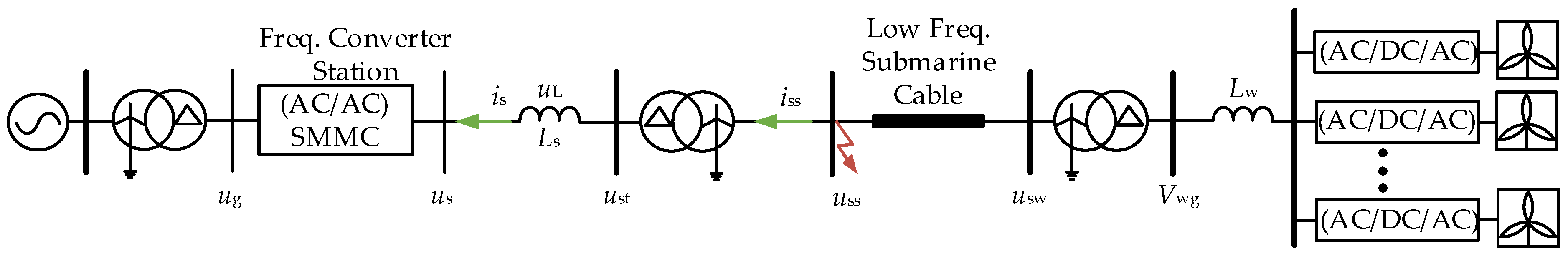
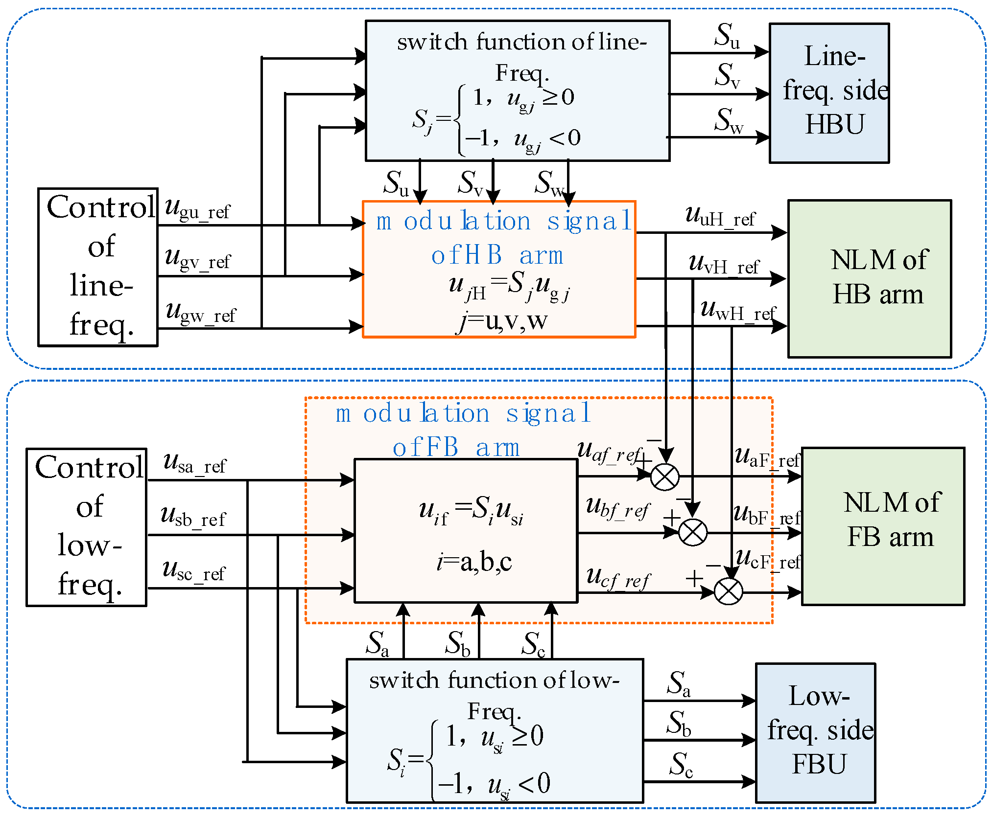
4.1. Control of Equivalent Converters for Wind Farms

During normal operations, the windfarm equivalent converter adopts a constant power control. Under asymmetric faults, it injects positive sequence dynamic reactive currents to support the recovery of positive sequence voltage and employs a control strategy for negative sequence current suppression to limit fault currents. In addition, according to the requirements of the Chinese National Standard, the dynamic positive sequence reactive current ratio coefficient of the windfarm is set to 0.9 [26]:
i w q + = K + ( 0 . 9 V wg + ) I fn i w d + = i max 2 i w q + 2 i w q = 0 i w d = 0
where iwq+ and iwq are the reference values of the positive and negative sequence reactive currents of the windfarm, respectively, while iwd+ and iwd are the reference values of the positive and negative sequence active currents of the windfarm, respectively. K+ is the proportional coefficient, and Vwg+ is the positive sequence component of the voltage at the windfarm grid connection point. imax and Ifn are the maximum value and rated value of the phase current amplitude, respectively.
The switching logic of the overall control strategy of the windfarm is shown in Figure 9, where ωw is the angular frequency of the windfarm system. Vwd+, Vwq+, Vwd, and Vwq are the positive and negative sequence d-q axis components of the voltage at the grid connection point, and Vwa, Vwb, and Vwc are the three-phase voltage modulation signals of the converter.

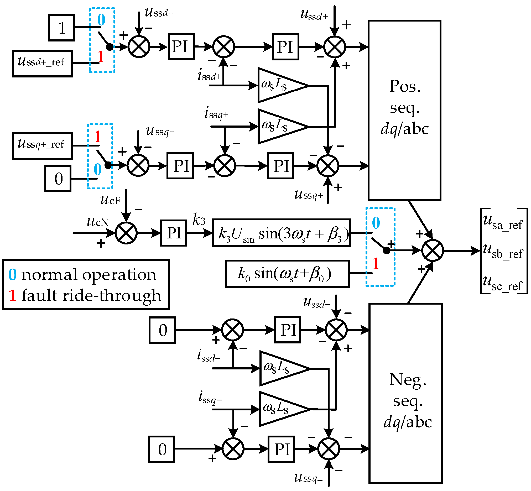
4.2. Asymmetric Fault Control on the Low-Frequency Side of the SMMC

During the fault, the positive sequence control strategy on the grid side of the SMMC remains unchanged, as shown in Figure 4. The reference value of the negative sequence current control loop is set to 0. On the low-frequency side, zero-sequence voltage should be injected during faults according to the energy balance constraints, and the reference value of the AC voltage control should be regulated to meet the specific power factor angle and prevent over-voltage in the non-faulted phases.
Because the zero-sequence voltage injection and the required power factor angle are different between single-phase to-ground faults and two-phase short-circuit faults, it is necessary to identify the fault type and to apply different voltage control commands. For single-phase to-ground short-circuits, the positive sequence and negative sequence voltages at the fault point are in opposite phases, and, for two-phase short-circuit faults, the positive sequence and negative sequence voltages at the fault point are in phase. The sign kf of the radio of the positive sequence voltage d-axis component ussd+ to the negative sequence voltage d-axis component ussd is used as feedback to determine the fault type:
k f = sgn ( u s s d + u s s d ) =   1 ,     single - phase   fault 1 , two - phase   fault
Afterwards, Equations (22) and (23) can be merged as follows:
k 0 = k f U fm β 0 = π 2 2 φ f
We can assume that, after the fault, the phase angle of the positive sequence current is+ on the low-frequency side of SMMC is θI, and the voltage amplitude of the equivalent inductance Lm is ULm, which can be expressed as:
θ I = arctan ( i s s q + i s s d + ) U Lm = ω s L s i s s d + 2 + i s s q + 2
where issd+ and issq+ represent the d-q axis components of the positive sequence current on the cable side of the transformer, respectively.
To simplify the analysis, the positive sequence voltage us+, the voltage uL, and the positive sequence voltage ust+ all refer to the transformer cable side. To suppress the non-fault-phase over-voltage, the reference value for the amplitude of us+, denoted as Ufm, is set to a fixed value of 0.58 pu [26]. To achieve arm energy balance, based on the analysis presented in Section 3.2 and Section 3.3, the phase angle θs of us+ should be:
θ s = π 6 + θ I ,   k f = 1 π 2 + θ I ,   k f = 1
The vector diagram of us+, uL, and ust+ is shown in Figure 10, where usd+ and usq+ represent the d-q axis components of us+, respectively, and ustd+ and ustq+ represent the d-q axis components of ust+, respectively.
The reference values for the transformer cable-side voltage ussd+_ref and ussq+_ref should be equal to the transformer converter side voltage referring to the cable side, ustd+ and ustq+. According to Figure 10, under a single-phase fault, the reference values can be obtained as:
u s s d + _ ref = U Lm + 4 U fm 2 3 U Lm 2 2 cos θ s U Lm sin θ I u s s q + _ ref = U Lm + 4 U fm 2 3 U Lm 2 2 sin θ s + U Lm cos θ I
Under a two-phase fault, the reference values can be obtained as:
u s s d + _ ref = 4 ( U fm 2 U Lm 2 ) 2 cos θ s U Lm sin θ I u s s q + _ ref = 4 ( U fm 2 U Lm 2 ) 2 sin θ s + U Lm cos θ I
Accordingly, the injected zero-sequence voltage component during a fault can be expressed as:
u 0 = k f U fm sin ( ω s t + θ s 2 φ f + π 2 )
In summary, the reference voltage commands for the positive sequence, negative sequence, and zero-sequence control components are superimposed to generate the low-frequency-side voltage modulation signals ua, ub, and uc. The low-frequency transformer can be eliminated, which has a certain impact on the control strategy. After removing the transformer, the phase of the voltage ust on the low-frequency transformer-converter side will change, and the control strategy only needs to swap the single-phase and two-phase components. The overall control block diagram for the low-frequency side is shown in Figure 11.
Voltage modulation signals ugu_ref, ugv_ref, and ugw_ref generate the switch functions Su, Sv, and Sw of HBU, which are used to modulate the half-bridge multi-level modulation signals uuH_ref, uvH_ref, and uwH_ref. The low-frequency side voltage modulation signals usa_ref, usb_ref, and usc_ref, derived from Figure 11, participate in determining the switch functions of FBU and are used to modulate the low-frequency half-wave signals uah_ref, ubh_ref, and uch_ref. These signals are then further modulated together with the line-frequency half-wave signals uuH_ref, uvH_ref, and uwH_ref to produce the full-bridge multi-level modulation signals uaF_ref, ubF_ref, and ucF_ref. The control block diagram for generating the switch signals and the arm multi-level modulation signals is shown in Figure 12. Specifically, modulation methods of the converter level such as pulse width modulation (PWM) [27] and NLM can be employed, and the latter is adopted in this paper.

5. Simulation Results

The offshore wind power low-frequency transmission system, as shown in Figure 3, was built in Matlab 2021a/Simulink, with the specific parameters listed in Table 1. Given that the focus of this study is the fault control of the SMMC, the offshore wind power farm is equivalently represented by a single VSC with an equivalent capacity of 2.5 MW, and the fault duration is set to 625 ms.

5.1. SMMC Normal Operations

Figure 13 shows the key waveforms of the SMMC during normal operations from 0 s to 0.1 s. As shown in Figure 13a,b, the grid-side full-wave multi-level voltage values ugu and uga are converted into a half-wave multi-level voltage uHu by the HBU switch. As shown in Figure 13c, the low-frequency full-wave multi-level voltage us is converted into a low-frequency half-wave multi-level voltage uha by the FBU switch. As shown in Figure 13d, the FBA voltage uFa is the difference between uha and uHu. The voltages uFka1,4 and uFka2,3 of ka1,4 and ka2,3 in the FBU are shown in Figure 13e, and the voltages uHka1,4 and uHka2,3 of ka1,4 and ka2,3 in the HBU are shown in Figure 13f.

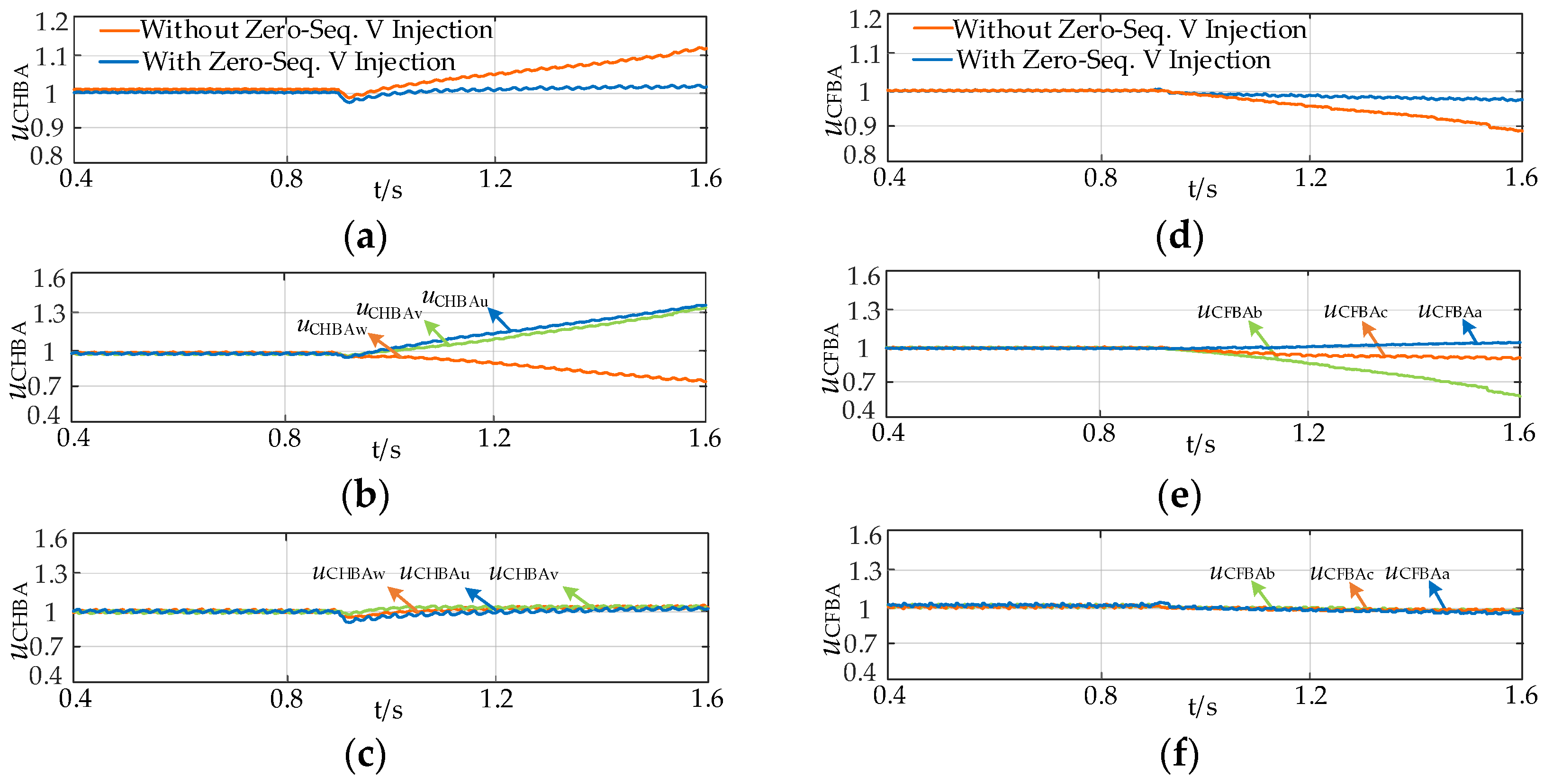
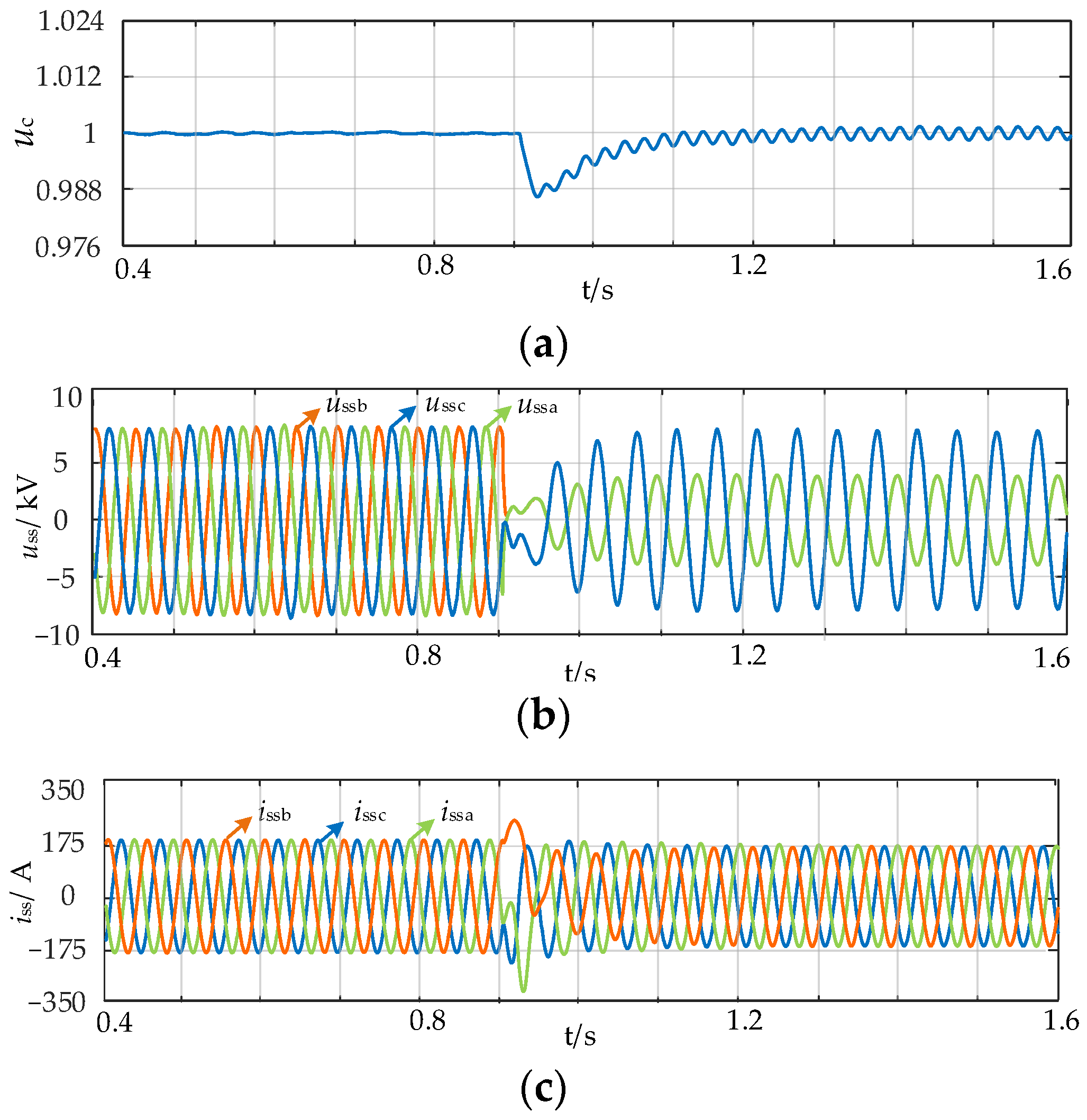
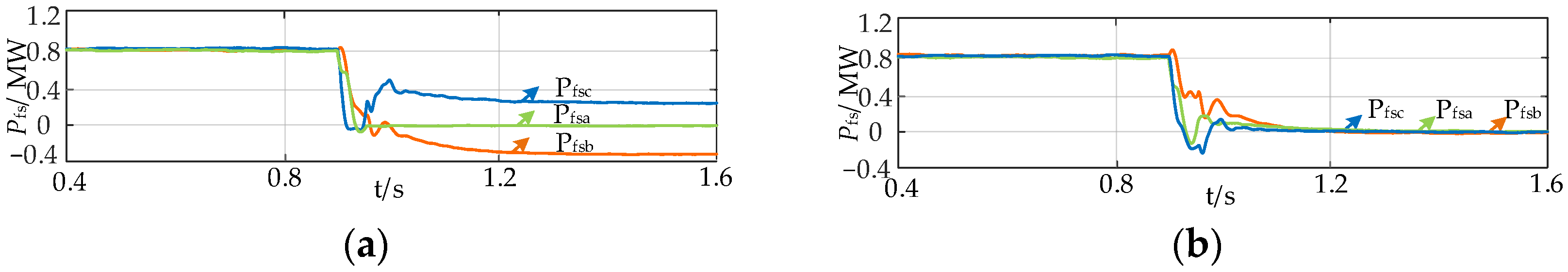
5.2. Single-Phase Ground Fault

To verify the control strategy proposed in this study, a single-phase ground fault is set at the low-frequency cable side of the SMMC station at 0.9 s. Upon detection of the negative sequence voltage and the fault type, zero-sequence voltage is injected into the low-frequency side of the SMMC. Simultaneously, the reference value of the low-frequency-side AC voltage is switched to achieve the specified power factor angle on the low-frequency side. The simulation results of the single-phase fault under the proposed control are shown in Figure 14. As shown in Figure 14a, the total average voltage of all the capacitors of the three-phase submodules, uC, remains at the rated value before and during the fault. Figure 14b shows that, under the conditions of overvoltage suppression control, the voltage of the non-fault-phase on the low-frequency cable side is regulated to the rated value, and the overvoltage is suppressed. As shown in Figure 14c, during the fault, the three-phase currents on the low-frequency side of the SMMC are symmetrical, and the negative sequence current is suppressed to zero.
Figure 15 shows the average value curves of the three-phase input power of the SMMC with and without the zero-sequence injection energy balance strategy. With a zero-sequence voltage injection, the zero-sequence power offsets the unbalanced impact of the negative sequence voltage on the three-phase input power, achieving symmetrical three-phase active power.
Figure 16 shows the sub-module capacitor voltage waveforms of the SMMC half-bridge and full-bridge arms under a single-phase fault, where uCHBAu, uCHBAv, and uCHBAw represent the average capacitor voltages of phase u, phase v, and phase w, respectively, and uCFBAa, uCFBAb, and uCFBAc represent the average capacitor voltages of phase a, phase b, and phase c, respectively. As shown in Figure 16, without the energy balance strategy, after the fault persists for 625 ms, the average value of the capacitor voltage of all sub-modules in the three-phase half-bridge arms deviates by about 15% from the rated value, and the degree of deviation varies among the three phases (approximately 30% for uCHBAu and 35% for uCHBAv and uCHBAw). This indicates a severe energy imbalance, which fails to meet the fault ride-through requirements. When the energy balance control strategy proposed in this study is adopted, the average capacitor voltage of all sub-modules in the three-phase half-bridge arms remains near the rated value. The average value of the sub-module capacitor voltages of each phase half-bridge briefly deviates from the rated value after the fault but essentially recovers to a balanced and stable state within about 0.1 s. At 625 ms after the fault occurring, the maximum voltage deviation does not exceed 5% of the rated value, which is beneficial to fault ride-through and fault recovery. The variations in the sub-module capacitor voltage of the full-bridge arms are similar to those of HBAs. Using the energy balance control strategy, the average capacitor voltage of all sub-modules in the three-phase full-bridge arms remains close to the rated value.

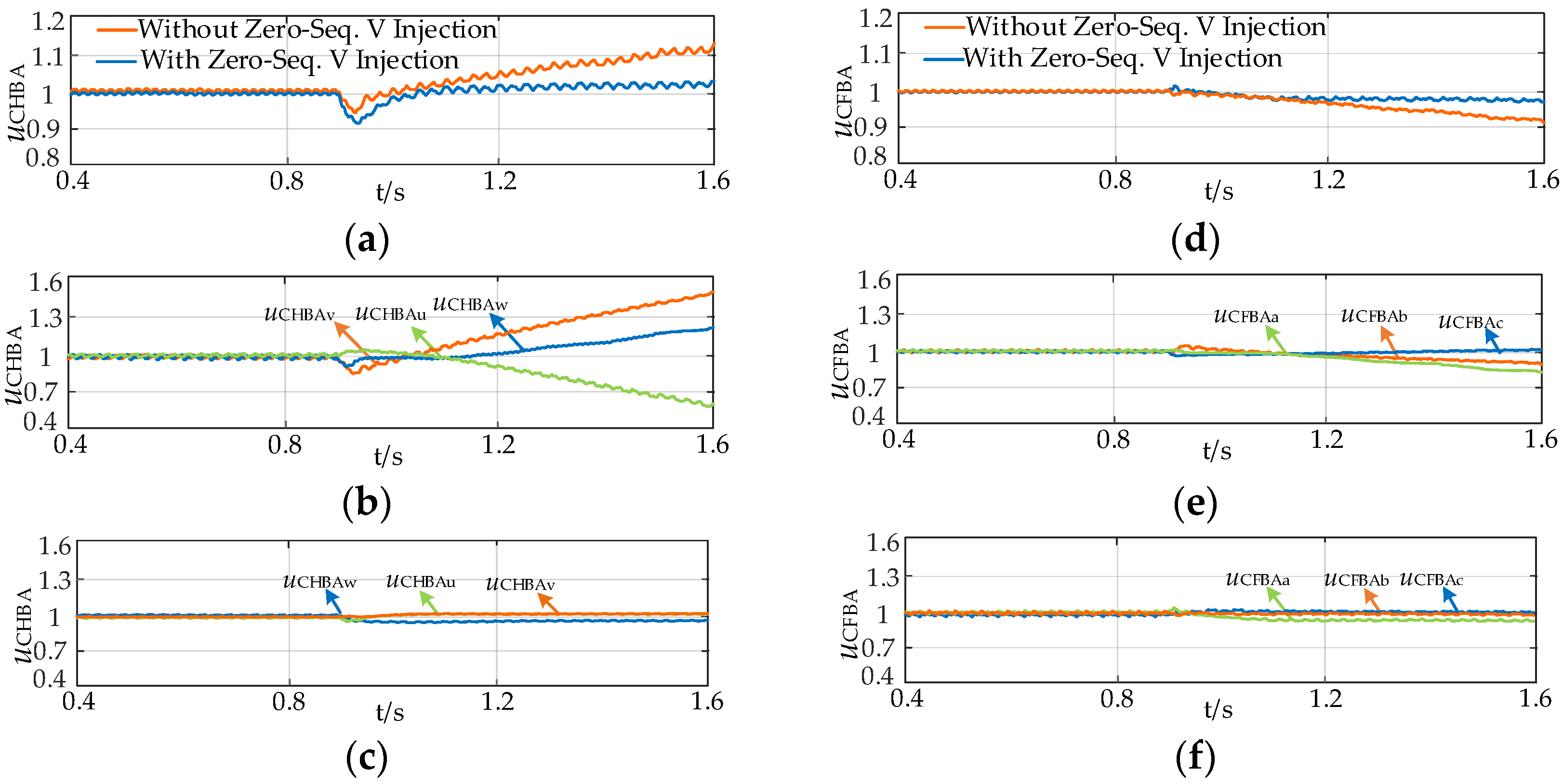
5.3. Two-Phase Interphase Short-Circuit Fault

Figure 17 shows the SMMC simulation results for a situation in which a two-phase short-circuit fault occurs between phase b and phase c in the low-frequency line. The average values of the capacitor voltage of the three-phase sub-modules and the low-frequency cable-side AC voltage and current are shown in Figure 17. The negative sequence current and overvoltage are suppressed after the fault, the average capacitor voltage of all sub-modules in the three-phase arms remains stable, and the total energy of the converter remains balanced.
Based on Figure 18, when using the zero-sequence injection energy balance strategy, the three-phase input power reaches equilibrium in 0.3 s after the fault.
The average capacitor voltages of the sub-modules in the three-phase and single-phase half-bridge and full-bridge arms are shown in Figure 19. Without the energy balance strategy, the average capacitor voltages of each phase in the half-bridge and full-bridge arms deviate significantly from the rated value and diverge over time, indicating a severe energy imbalance that fails to meet fault ride-through requirements. In contrast, when using the energy balance control strategy proposed in this study, the average capacitor voltages of the sub-modules in the half-bridge and full-bridge arms enter a stable state approximately 0.1 s after the fault, not diverging over time. At 625 ms after the fault, the voltage deviation is within 10% of the rated value, which is beneficial for fault ride-through and fault recovery.

6. Conclusions

Targeting the SMMC low-frequency transmission system, this study proposes an arm energy balance method and a fault ride-through control strategy under asymmetric faults, with the aim of achieving the safe and stable operation of the system. Based on a theoretical analysis and simulations, the following conclusions can be drawn:
  • When an asymmetric fault occurs on the low-frequency side of the SMMC transformer, the asymmetric phase voltage causes different balancing targets for the three-phase arms of the SMMC. Using the traditional control strategy in this situation will result in an imbalanced distribution of energy among phases and within phases, threatening the stable operation of the system.
  • Based on the analysis of the energy imbalance mechanism, under asymmetric faults on the low-frequency side, the amplitude and phase of the zero-sequence voltage injection in the SMMC must meet specific conditions to achieve energy balance in all arms, ensuring the capacitor voltage in the half-bridge and full-bridge arm modules does not exceed 10%, which is beneficial for fault ride-through and fault recovery.
  • The proposed fault ride-through strategy for the low-frequency transmission system, based on a zero-sequence voltage injection and constant power factor angle AC voltage control, can maintain energy balance in the half-bridge and full-bridge arms of the SMMC while suppressing negative sequence current and overvoltage. This ensures the ride-through of asymmetric faults on the low-frequency side.

Author Contributions

Conceptualization, Y.S. and S.W.; methodology, Y.S.; software, Y.S. and S.W.; validation, Y.S., S.W. and C.F.; formal analysis, Y.S. and Z.Z.; investigation, Y.S. and S.W.; resources, Y.S. and C.F.; data curation, Y.S., G.Z. and Z.Z.; writing—original draft preparation, Y.S. and S.W.; writing—review and editing, Y.S., S.W., C.F., Z.Z., G.Z., Y.X., B.L. and C.J.; visualization, G.Z. and C.J.; supervision, S.W., C.F. and B.L.; project administration, G.Z., Y.X. and B.L.; funding acquisition, G.Z. and C.J. All authors have read and agreed to the published version of the manuscript.

Funding

This research was funded by State Grid Corporation Headquarters Science and Technology Project, grant number 5108-202218280A-2-340-XG.

Data Availability Statement

The original contributions presented in the study are included in the article; further inquiries can be directed to the corresponding author.

Conflicts of Interest

Author Chen Jia was employed by the company Electric Power Research Institute of State Grid Liaoning Electric Power Co., Ltd. The remaining authors declare that the research was conducted in the absence of any commercial or financial relationships that could be construed as a potential conflict of interest.

References

  1. Kabsha, M.M.; Rather, Z.H. Adaptive Control Strategy for Frequency Support From MTDC Connected Offshore Wind Power Plants. IEEE Trans. Power Electron. 2023, 38, 3981–3991. [Google Scholar] [CrossRef]
  2. Zhang, T.; Sun, L.; Zhang, Y. Study on Switching Overvoltage in Off-Shore Wind Farms. IEEE Trans. Appl. Supercond. 2014, 24, 1–5. [Google Scholar] [CrossRef]
  3. Nguyen, Q.; Santoso, S. Optimal Planning and Operation of Multi-Frequency HVac Transmission Systems. IEEE Trans. Power Syst. 2021, 36, 689–698. [Google Scholar] [CrossRef]
  4. Wang, X.; Duan, Z.; Meng, Y. Review of operational characteristics and control strategies of fractional frequency transmission systems. High Volt. Eng. 2023, 49, 3696–3707. [Google Scholar] [CrossRef]
  5. Afshari, E.; Amirabadi, M. An Input-Series Output-Parallel Modular Three-Phase AC–AC Capacitive-Link Power Converter. IEEE Trans. Power Electron. 2021, 36, 13603–13620. [Google Scholar] [CrossRef]
  6. Luo, J.; Zhang, X.-P.; Xue, Y. Small Signal Model of Modular Multilevel Matrix Converter for Fractional Frequency Transmission System. IEEE Access 2019, 7, 110187–110196. [Google Scholar] [CrossRef]
  7. Cuzmar, R.H.; Mora, A.; Pereda, J.R.; Aguilera, P.; Poblete, P.; Neira, S. Computationally Efficient MPC for Modular Multilevel Matrix Converters Operating With Fixed Switching Frequency. IEEE Open J. Ind. Electron. Soc. 2023, 4, 748–761. [Google Scholar] [CrossRef]
  8. Duan, Z.; Meng, Y.; Duan, Y.; Zhang, H.; Wang, X.; Wang, X. Large-Signal Stability Analysis and Enhancement of Modular Multilevel Matrix Converter Under Power Fluctuation Based on T-S Fuzzy Model Theory. IEEE Trans. Power Electron. 2023, 38, 14601–14613. [Google Scholar] [CrossRef]
  9. Liu, B.; Meng, Y.; Bai, S. A novel high-power AC/AC modular multilevel converter in Y configuration and its control strategy. In Proceedings of the 2016 IEEE PES Asia-Pacific Power and Energy Engineering Conference (APPEEC), Xi’an, China, 25–28 October 2016; pp. 973–977. [Google Scholar] [CrossRef]
  10. Baruschka, L.; Mertens, A. A New Three-Phase AC/AC Modular Multilevel Converter With Six Branches in Hexagonal Configuration. IEEE Trans. Ind. Appl. 2013, 49, 1400–1410. [Google Scholar] [CrossRef]
  11. Alaei, R.; Khajehoddin, S.A.; Xu, W. Sparse AC/AC Modular Multilevel Converter. IEEE Trans. Power Deliv. 2016, 31, 1195–1202. [Google Scholar] [CrossRef]
  12. Alaei, R.; Khajehoddin, S.A.; Xu, W. Control and Experiment of AC/AC Sparse Modular Multilevel Converter. IEEE Trans. Power Deliv. 2017, 32, 1527–1534. [Google Scholar] [CrossRef]
  13. Li, J.; Ma, M.; Chen, Q.; Wang, H.; Zhao, G.; Xu, Y. Basic modulation strategy and sub-module voltage balancing control for half-wave inverter AC-AC converter. In Proceedings of the 2023 IEEE 6th International Electrical and Energy Conference (CIEEC), Hefei, China, 12–14 May 2023; pp. 2672–2677. [Google Scholar]
  14. Fu, N.; Liu, B.; Xu, Y.; Zhu, S.; Wang, K.; Li, Y. Capacitor voltage balancing strategy based on zero-Sequence voltage injection for half-wave commutated modular multilevel converter. In Proceedings of the 10th International Power Electronics and Motion Control Conference, IPEMC 2024-ECCE Asia, Chengdu, China, 17–20 May 2024. [Google Scholar]
  15. Sun, Y.; Wang, T.; Fu, C.; Guo, F.; Ni, Q. Fault ride through control strategy for modular multilevel matrix converter for fractional frequency transmission system. High Volt. Eng. 2023, 49, 19–30. [Google Scholar] [CrossRef]
  16. Zhao, B.; Wang, X.; Ning, L.; Wang, X.; Meng, Y. Ride-through control of fractional frequency offshore wind power system during unsymmetrical grid faults. Proc. CSEE 2023, 43, 4589–4600. [Google Scholar] [CrossRef]
  17. Xie, D.; Lin, C.; Deng, Q.; Lin, H.; Cai, C.; Basler, T.; Ge, X. Simple Vector Calculation and Constraint-Based Fault-Tolerant Control for a Single-Phase CHBMC. IEEE Trans. Power Electron. 2025, 40, 2028–2041. [Google Scholar] [CrossRef]
  18. Hu, K.; Zhao, G.; Lu, D.; Lu, Z.; Xiang, N.; Wang, S.; Lin, J. Simplified Cluster Voltage Balancing Control Based on Zero-Sequence Voltage Injection for Star-Connected Cascaded H-Bridge STATCOM. CSEE J. Power Energy Syst. 2024, 10, 2255–2264. [Google Scholar] [CrossRef]
  19. Zhang, R.; Wang, S.; Ma, J.; Wang, P.; Qin, K.; Liu, T. Capacitor Voltage Balancing for Alternate Arm Converter Based on Conduction Angle and Zero-Sequence Voltage. IEEE Trans. Power Electron. 2023, 38, 3268–3280. [Google Scholar] [CrossRef]
  20. Spier, D.W.; Prieto-Araujo, E.; López-Mestre, J.; Mehrjerdi, H.; Gomis-Bellmunt, O. On the Roles and Interactions of the MMC Internal Energy Balancing Degrees of Freedom for Three-Wire Three-Phase Connections. IEEE Trans. Power Deliv. 2023, 38, 1316–1328. [Google Scholar] [CrossRef]
  21. Ma, J.; Dahidah, M.S.A.; Pickert, V.; Yu, J. A Hierarchical Energy Balance Control Method for M3C Based on Injecting Output Frequency Circulating Currents. IEEE Trans. Power Electron. 2020, 35, 2424–2435. [Google Scholar] [CrossRef]
  22. Aguilera, R.P.; Acuna, P.; Rojas, C.; Pou, J.; Konstantinou, G.; Watanabe, E.H. An Instantaneous Power Theory Extension for the Interphase Power Imbalance Problem. IEEE Trans. Power Electron. 2024, 39, 12261–12270. [Google Scholar] [CrossRef]
  23. RAguilera, P.; Acuna, P.; Rojas, C.A.; Konstantinou, G.; Pou, J. Instantaneous Zero Sequence Voltage for Grid Energy Balancing Under Unbalanced Power Generation. In Proceedings of the 2019 IEEE Energy Conversion Congress and Exposition (ECCE), Baltimore, MD, USA, 29 September–3 October 2019; pp. 2572–2577. [Google Scholar] [CrossRef]
  24. Li, Y.; Pei, X.; Yang, M.; Lin, X.; Li, Z. An Advanced Fault Control of Transformerless Modular Multilevel Converters in AC/DC Hybrid Distribution Networks Under the Single-Phase Grounding Fault. IEEE Trans. Power Deliv. 2021, 36, 932–942. [Google Scholar] [CrossRef]
  25. Wang, X.; Yang, L.; Lin, B.; Song, W.; Lin, L. Mechanism and restraining strategy of the sending-end line overvoltage in offshore wind farm-flexible HVDC transmission system under line faults. High Volt. Eng. 2021, 47, 2688–2697. [Google Scholar] [CrossRef]
  26. GB/T 19966.1-2021; Technical Regulations for the Connection of Wind Farms to Power Systems—Part 1: Onshore Wind Farms. China National Standardization Administration: Beijing, China, 2021.
  27. Lin, H.; Cai, C.; Chen, J.; Gao, Y.; Vazquez, S.; Li, Y. Modulation and Control Independent Dead-Zone Compensation for H-Bridge Converters: A Simplified Digital Logic Scheme. IEEE Trans. Ind. Electron. 2024, 71, 15239–15244. [Google Scholar] [CrossRef]
Figure 1. Topology of the SMMC. (a) Single-phase SMMC topology; (b) Three-phase SMMC topology.
Electronics 14 00426 g001
Figure 2. Internal power distribution of the single-phase SMMC.
Electronics 14 00426 g002
Figure 3. Offshore low-frequency transmission system based on an SMMC.
Electronics 14 00426 g003
Figure 4. Control strategy of the SMMC under normal operational conditions.
Electronics 14 00426 g004
Figure 5. Energy deviation of the arm with a third harmonic injection under a single phase-to-ground fault. (a) Relationship between the third harmonic injection amplitude and energy deviation of the half-bridge arm; (b) relationship between the third harmonic injection amplitude and energy deviation of the full-bridge arm.
Electronics 14 00426 g005
Figure 6. Energy deviation of an arm with a zero-sequence injection under a single phase-to-ground fault. (a) Energy deviation of HBAs; (b) energy deviation of FBAs.
Electronics 14 00426 g006
Figure 7. Energy deviation of the arm during a single-phase fault within one cycle with a zero-sequence injection. (a) HB arm; (b) FB arm.
Electronics 14 00426 g007
Figure 8. Energy deviation of the arm with a zero-sequence injection under a phase-to-phase fault. (a) Energy deviation of HBAs; (b) energy deviation of FBAs.
Electronics 14 00426 g008
Figure 9. Control strategy of the equivalent converter of the windfarm.
Electronics 14 00426 g009
Figure 10. Low-frequency-side voltage vector relationship.
Electronics 14 00426 g010
Figure 11. Low-frequency-side overall control strategy of SMMC.
Electronics 14 00426 g011
Figure 12. Control diagram of switch of unfolder and arm modulation of SMMC.
Electronics 14 00426 g012
Figure 13. The waveforms of (a) ugu, usa; (b) uHu; (c) uha; (d) uFa; (e) uFka1,4, uFka2,3; (f) uHka1,4, uHka2,3.
Electronics 14 00426 g013aElectronics 14 00426 g013b
Figure 14. Simulation waveforms of the SMMC with the proposed control under a single-phase ground fault. (a) Average voltage of all sub-module capacitors; (b) low-frequency cable-side AC voltage; (c) low-frequency cable-side AC current.
Electronics 14 00426 g014
Figure 15. Average input power on the low-frequency side of SMMC under a single-phase-to-ground fault. (a) Without the zero-sequence voltage injection; (b) with the zero-sequence voltage injection.
Electronics 14 00426 g015
Figure 16. Half-bridge and full-bridge SM capacitor voltage of the SMMC under a single-phase to-ground fault. (a) Average capacitor voltage of all SMs in the HBA in the three phases; (b) average capacitor voltage of the HBA in each phase (without a zero-sequence voltage injection); (c) average capacitor voltage of the HBA in each phase (with zero-sequence voltage injection); (d) average capacitor voltage of all SMs in the FBA of the three phases; (e) average capacitor voltage of FBAs in each phase (without zero-sequence voltage injection); (f) average capacitor voltage of FBA in each phase (with zero-sequence voltage injection).
Electronics 14 00426 g016
Figure 17. Simulation waveforms of SMMC with the proposed control under a phase-to-phase fault. (a) Average capacitor voltage of all SMs; (b) AC voltage on the cable side of the low-frequency side; (c) AC current on the cable side of the low-frequency side.
Electronics 14 00426 g017
Figure 18. Average input power on the low-frequency side of SMMC under a phase-to-phase fault. (a) Without the zero-sequence voltage injection; (b) with the zero-sequence voltage injection.
Electronics 14 00426 g018
Figure 19. Half-bridge and full-bridge submodule capacitor voltage of the SMMC under a phase-to-phase fault. (a) Average capacitor voltage of all SMs in the HBA of the three phases; (b) average capacitor voltage of HBA in each phase (without zero-sequence voltage injection); (c) average capacitor voltage of HBA in each phase (with zero-sequence voltage injection); (d) average capacitor voltage of all SMs in the FBA of the three phases; (e) average capacitor voltage of FBAs in each phase (without zero-sequence voltage injection); (f) average capacitor voltage of FBA in each phase (with zero-sequence voltage injection).
Electronics 14 00426 g019
Table 1. Simulation parameters of the SMMC.
ParametersValueParametersValue
Power rating Sn/MW2.5Sub-module capacitor voltage uCN/kV1.5
Number of SMs/N15Low-frequency-side rated voltage Usm/kV10
Internal arm inductance Larm/mH1Grid-side rated voltage Ugm/kV10
Low-frequency-side equivalent inductance Ls/mH5Low-frequency-side frequency f1/Hz20
SM capacitor C/mF10Grid-side frequency f2/Hz50
Disclaimer/Publisher’s Note: The statements, opinions and data contained in all publications are solely those of the individual author(s) and contributor(s) and not of MDPI and/or the editor(s). MDPI and/or the editor(s) disclaim responsibility for any injury to people or property resulting from any ideas, methods, instructions or products referred to in the content.

