Article

Coprime Distributed Array for Super-Resolution DOA Estimation

1
School of Electronic and Optical Engineering, Nanjing University of Science and Technology ZiJin College, Nanjing 210023, China
2
Shanghai Radio Equipment Research Institute, Shanghai 201109, China
3
Nanjing Electronic Equipment Research Institute, Nanjing 211100, China
*
Authors to whom correspondence should be addressed.
Electronics 2025, 14(23), 4562; https://doi.org/10.3390/electronics14234562
Submission received: 12 October 2025 / Revised: 19 November 2025 / Accepted: 20 November 2025 / Published: 21 November 2025
(This article belongs to the Special Issue Advances in Array Signal Processing: Methods and Applications)

Abstract

The increasing complexity of the electromagnetic environment, driven by rapid advancements in communication and radar technologies, places greater demands on direction of arrival (DOA) estimation. While traditional antenna arrays improve performance by increasing the number of elements, this approach raises hardware costs and design complexity with reducing system flexibility. Distributed arrays offer a promising alternative by enhancing angular accuracy and resolution without additional elements. However, conventional uniformly distributed radars suffer from high hardware costs and computational complexity. To overcome this issue, this paper proposes a distributed radar architecture based on a coprime arrangement. By deploying two subarrays with coprime spacings, the proposed structure significantly reduces hardware requirements while maintaining high angle estimation accuracy. Simulations validate the effectiveness of the proposed configuration. Under the conditions of a signal-to-noise ratio of 0 dB and 50 snapshots, the angle measurement error reached ( 10 3 )°.

1. Introduction

Direction of arrival (DOA) estimation is the foundation of array signal processing and has important applications in radar, sonar, wireless communications, and astronomical observations [1,2,3,4]. Its core goal is to determine the directions of multiple electromagnetic or acoustic wavefronts impinging on a sensor array. In the past few decades, a large number of super-resolution algorithms have been developed to surpass the Rayleigh resolution limit of traditional beamforming [5,6,7]. Among them, subspace-based methods such as multiple signal classification (MUSIC) [8] proposed by Schmidt and estimation of signal parameters via rotational invariance techniques (ESPRIT) [9] proposed by Roy have become benchmarks due to their high estimation accuracy. Furthermore, the accurate estimation of the direction of arrival is not only crucial for localization but also serves as the foundational step for adaptive beamforming and dynamic beamsteering in modern phased-array systems [10]. For instance, the integration of DOA estimation with advanced frequency synthesizers, such as DDS-PLL architectures, enables real-time beam alignment and tracking, which is vital for enhancing the capacity and reliability of wireless links [11,12]. A technique for estimating AoA using phase interferometry when multiple sources are present is proposed by Florio et al., which is suitable for implementation in dedicated digital hardware [13,14,15].
Studying the one-dimensional (1D) case is a crucial and routine first step in array signal processing research. In the 1D DOA estimation, the uniform linear array (ULA) is a preferred architecture due to their mathematical tractability [16,17,18,19]. However, the degrees of freedom (DOF) and resolution of a ULA are fundamentally limited by the number of physical sensors, and it contains that an N-elements ULA can resolve at most N 1 sources. This necessitates a large number of sensors for high-performance applications resulting in increasing hardware cost, power consumption, and mutual coupling effects, and those would degrade performance of the system [20,21,22,23].
To break this fundamental trade-off, sparse array architecture has emerged as a revolutionary paradigm [24]. Commonly used sparse arrays include minimum redundancy arrays (MRA) [25], coprime arrays [26], and nested arrays [27,28]. Although MRA provides the most uniform degrees of freedom (uDOFs), it lacks a closed expression for sensor locations. Nested arrays consist of two subarrays in series, one of which has an element spacing of half the wavelength. However, due to the dense arrangement of ULA segments in the nested array structure, it is more susceptible to mutual coupling effects [29]. In contrast, it is worth noting that coprime arrays, pioneered by [30], have attracted great attention. The general structure of a coprime array consists of two sets of uniform subarrays with coprime element spacing and number. A coprime array consisting of two sparse inter-element coprime arrays can generate a “virtual” differential common array with an aperture much larger than that of a physical array. This makes it possible to identify O ( M + N ) physical sensors, providing a significantly increased DOF [26]. In practical applications, the mutual coupling effect in nested arrays is more significant than that in coprime arrays.
In the parallel research thrust, distributed arrays (or multi-aperture arrays) have been studied for their inherent ultra-high angular resolution. By deploying subarrays across a large physical aperture, these systems can resolve closely spaced sources, and that would be indistinguishable from a co-located array of the same size. The dual resolution-ESPRIT (DR-ESPRIT) algorithm, proposed by Wong et al., is a classic distributed array DOA estimation algorithm [31]. A weighted signal subspace MUSIC (WSSMUSIC) algorithm based on a distributed nested array is presented in [32] proposed by Liao et al. Compared with a ULA, the WSSMUSIC can expand the physical aperture and improve the DOA estimation performance without increasing the number of array elements and computational complexity. In [33], an L-type distributed augmented nested array structure is used to achieve rank recovery of the covariance matrix by removing redundancy and spatial smoothing, thereby performing two-dimensional arrival angle estimation of the incoming signal. In [34], Vasylyshyn proposes a disambiguation algorithm based on a dual V-type distributed array. Then, the spatial spectra of the two V-type subarrays are obtained using the MUSIC algorithm, and the spectrum peak corresponding to the real target is retained by designing a threshold, thereby achieving disambiguation.
However, conventional distributed arrays typically use densely packed ULAs as subarrays and lack systematic design principles for the geometry between subarrays, often resulting in grating lobes and underutilized degrees of freedom. A distributed sparse array structure consisting of multiple subarrays, which uses information fusion on the received data matrix of the subarray based on matrix completion, is proposed in [32,35,36], and those approaches not only improve the DOA estimation performance but also increase the DOF of the array. In addition, this method can effectively perform DOA estimation when the number of signal sources is greater than the number of array elements. Xie et al. use tensor sequence decomposition to achieve joint estimation of two-dimensional direction-of-departure (2D-DOD) and two-dimensional DOA (2D-DOA) in a bistatic radar system [37,38]. In [39], Pavel et al. propose an iterative adaptive approach for distributed millimeter-wave radar with a single snapshot and coherent sources.
The powerful concept of structured sparsity, proven effective in colocalized arrays, has not been systematically integrated in the design of resolution-enhancing distributed arrays. Conventional colocalized arrays focus on sensor-level sparsity but are limited to a single aperture, limiting their ultimate resolution. Conversely, conventional distributed arrays exploit large physical apertures but lack complex sparsity geometries, resulting in suboptimal DOF and unresolvable ambiguities. The potential of unified structures embodying distributed sparsity, where subarrays are themselves sparse relative to each other has been overlooked. To address these issues, this paper proposes a novel array configuration based on ULAs, called Coprime Distributed Array (CDA). By limiting our analysis to 1D using ULAs, we can isolate and clearly demonstrate the fundamental advantages of our proposed architecture without incurring the additional complexity of 2D geometry, coupling, and algorithmic formulation. The linear array structure allows for more direct comparisons of performance metrics such as resolution and estimation error. The main contributions of this work are threefold:
  • Array Geometry: We introduce a systematic geometry for distributing prime subarrays to form a large and sparse aperture. This structure is designed to maximize the array aperture, thereby simultaneously improving achievable depth of field and resolution. This new distributed structure, which elevates the concept of coprime arrays from the sensor level to the subarray level, represents a paradigm shift in array design.
  • Theoretical and Numerical Analysis: Comprehensive simulations quantify the significant advantages of the proposed structure in estimation accuracy and resolution. We designed systematic experiments comparing the CDA with benchmark structures, such as the traditional ULA and uniformly distributed array (UDA). The results clearly demonstrate that, at the same hardware cost, the proposed structure achieves significant improvements in key metrics including estimation error and angular resolution.
  • Performance–Parameter Relationship: We clearly delineate the relationship between performance and key parameters (e.g., baseline length and number of snapshots), providing valuable design guidelines for practical engineering applications.
The remainder of this paper is organized as follows: Section 2 details the signal model and DOA estimation principle. Section 3 introduces the proposed CDA architecture and parameter configuration. Section 4 presents simulation results and comparative analyses. Finally, Section 5 concludes the paper and outlines future research directions.

2. Signal Model

Subspace-based super-resolution DOA estimation algorithms include the MUSIC and ESPRIT algorithms. And they are both developed based on the ULA model. In this section, we provide a brief overview of DOA estimation implementations based on ULAs. We also introduce a UDA model based on ULAs and analyze its characteristics.

2.1. ULA Model

The ULA is the most common one-dimensional array structure. In a ULA, antenna elements are arranged in a straight line with uniform spacing between antenna elements. We first make assumptions about the relevant model. The relevant assumptions are as follows:
(1)
The signal received by the antenna receiving array is a far-field plane wave signal.
(2)
The various signal sources are uncorrelated, and the incident signal is a narrowband signal; that is, the carrier frequency of the signal is greater than the bandwidth of the signal.
(3)
The number of signal sources of the incident signal is known.
(4)
The array elements in the antenna array are isotropic; that is, the antenna gain does not change with the direction of the incident wave. The noise received by each array element is Gaussian white noise, and the noise is uncorrelated with the signal.
We assume that the number of receiving elements in a ULA is L, and the spacing between elements is d. When the signal source to be estimated is incident on the ULA, since the incident signal is a far-field plane wave, the angle between the incident wave signal and the normal of the receiving antenna array element is the estimated incident wave direction, as shown in Figure 1.
Assume that K narrowband signals s 1 ( t ) , s 2 ( t ) , , s K ( t ) are incident on a uniform linear receiving array with an incident angle of θ k ( k = 1 , 2 , K ). The first element is used as the reference element. There is a distance difference between the signal from the l-th ( l = 1 , 2 , L ) element and the reference element. The distance difference is expressed as follows.
Δ l k = l d sin ( θ k ) .
The time delay of the l-th array element receiving the k-th signal can be expressed as
τ l k = Δ l k c = l d sin ( θ k ) c ,
where c represents the speed of light. Then the received signal of the l-th array element is
x l t = k = 1 K g l k s k t τ l k + n l t , l = 1 , 2 , , L ,
where g l k is the gain of l-th array element for the k-th signal, and n l t corresponding to the noise of the l-th array element. According to assumption (2), for narrowband signals, the time delay τ l k is approximately equal to a phase shift e j ω 0 τ l k , where ω 0 = 2 π f and f represents the carrier frequency of the signal. The receiving matrix of the ULA is expressed as follows:
x 1 ( t ) x 2 ( t ) x L ( t ) = g 11 e j ω 0 τ 11 g 12 e j ω 0 τ 12 g 1 K e j ω 0 τ 1 K g 21 e j ω 0 τ 21 g 22 e j ω 0 τ 22 g 2 K e j ω 0 τ 2 K g L 1 e j ω 0 τ L 1 g L 2 e j ω 0 τ L 2 g L K e j ω 0 τ L K s 1 ( t ) s 2 ( t ) s K ( t ) + n 1 ( t ) n 2 ( t ) n L ( t ) ,
Simplify the formula based on the assumption (4):
x 1 ( t ) x 2 ( t ) x L ( t ) = e j ω 0 τ 11 e j ω 0 τ 12 e j ω 0 τ 1 K e j ω 0 τ 11 e j ω 0 τ 22 e j ω 0 τ 2 K e j ω 0 τ L 1 e j ω 0 τ L 2 e j ω 0 τ L K s 1 ( t ) s 2 ( t ) s K ( t ) + n 1 ( t ) n 2 ( t ) n L ( t ) .
The vector form of Equation (5) is given as
x ( t ) = As ( t ) + n ( t ) .
In the Equation (6), x ( t ) represents the ( L × 1 )-dimensional vector of the array, A is the guiding vector matrix with a dimension of L × K . s is the ( K × 1 )-dimensional received signal vector, and n is the ( L × 1 )-dimensional noise vector.

2.2. DOA Estimation Algorithm

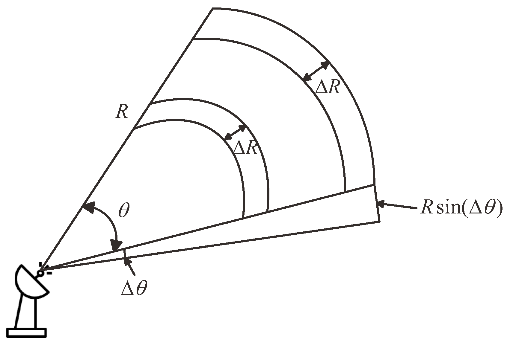
From a physical, geometric perspective, under specific signal-to-noise ratio (SNR) conditions, the measurement error in the range dimension of each radar station is decoupled from the actual distance between the radar and the target. This means that the measurement error in the range dimension is unaffected by changes in the distance between the radar and the target. However, when considering the angular dimension, a different phenomenon is observed: as the distance between the radar and the target increases, the spatial positioning error introduced by the angular measurement increases linearly. This characteristic constitutes the main challenge and limitation faced by single-station radar in accurately locating long-range targets. Figure 2 provides an intuitive geometric description of the positioning error introduced by single-station radar range and angular measurements.
Therefore, improving the angle estimation accuracy is crucial to improving the positioning accuracy over long distances. The super-resolution DOA estimation algorithm provides an estimation accuracy beyond the Rayleigh limit, greatly improving the angular resolution. The MUSIC algorithm introduces spatial vectors into the field of spatial spectrum estimation. Since then, this algorithm has been extensively and deeply researched. This section introduces the basic principles of the algorithm.
The covariance matrix R x of the receiving array can be derived from the receiving array signal model in the previous section:
R x = A R s A H + R N = A R s A H + σ 2 I ,
where, R s is the covariance matrix of the desired signal, R N is the covariance matrix of the noise, σ 2 is the variance of the noise, and I is the identity matrix. The covariance matrix of the received signal matrix is then eigendecomposed to obtain the corresponding eigenvalues q i ( i = 1 , 2 , L ) and the eigenvectors v i ( i = 1 , 2 , L ) corresponding to these eigenvalues. The eigenvalues are then arranged from largest to smallest, such that q 1 q 2 q L > 0 . The eigenvectors corresponding to the first K largest eigenvalues constitute the received signal subspace, while the eigenvectors corresponding to the remaining eigenvalues constitute the noise subspace. Assume that the eigenvalue of the covariance matrix of the received signal corresponds to the eigenvector, and we have
R x v i = q i v i .
The smaller eigenvalue of the covariance matrix is q i = σ 2 , then we can get
R x v i = σ 2 v i , i = K + 1 , K + 2 , , L .
Substituting the Equation (9) into the Equation (8), we can get
σ 2 v i = A R s A H + σ 2 I v i .
The Equation (10) shows that the column vectors of the steering vector matrix are orthogonal to the eigenvectors in the noise subspace, and the column vectors in the steering vector contain the direction of the incoming wave. Therefore, the orthogonality between the noise subspace and the incoming wave signal can be used to determine the direction of the incoming wave by searching with an angle.
The eigenvectors corresponding to the noise constitute the noise subspace:
E n = v K + 1 , v K + 2 , , v L .
Thus, the spatial spectrum function is defined as
P ( θ ) = 1 a H ( θ ) E n E n H a ( θ ) .
The spatial spectrum function is mainly achieved by continuously changing in the steering vector a ( θ ) . When θ is the incoming wave direction of the received signal, it is orthogonal to the constructed noise subspace. At this time, the denominator has a minimum value, and the spectrum function shows a spectrum peak. By continuously changing the angle θ , the spectrum function is searched. When the value θ is the incoming wave direction, the spectrum function has a spectrum peak, which is the estimated angle value of the incoming wave direction.

3. The Distributed Array and the Proposed Architecture

Limited by physical baseline length, single-station radar cannot fully exploit its potential angular resolution, posing a significant challenge for accurate long-range target localization.
Distributed radar systems overcome this limitation by deploying sensors over a larger geographic area, effectively increasing the baseline. Distributed arrays improve angular accuracy and resolution without increasing the number of elements per subarray. Comprising multiple subarrays distributed in space, they form a virtual aperture whose equivalent size exceeds the sum of individual subarray apertures. This configuration enhances system mobility, flexibility, and scalability.

3.1. Principles of Distributed Arrays

This paper focuses on common-baseline distributed arrays, where all subarrays lie on the same line. Since the mainlobe beamwidth of the array pattern directly relates to angle estimation accuracy (typically one-tenth to a few tenths of the beamwidth), the pattern can be used to analyze performance. The array pattern steered to θ 0 for a ULA with L elements is expressed as [40]
G ( θ ) = sin π 2 M ( sin θ sin θ 0 ) L sin π 2 ( sin θ sin θ 0 ) .
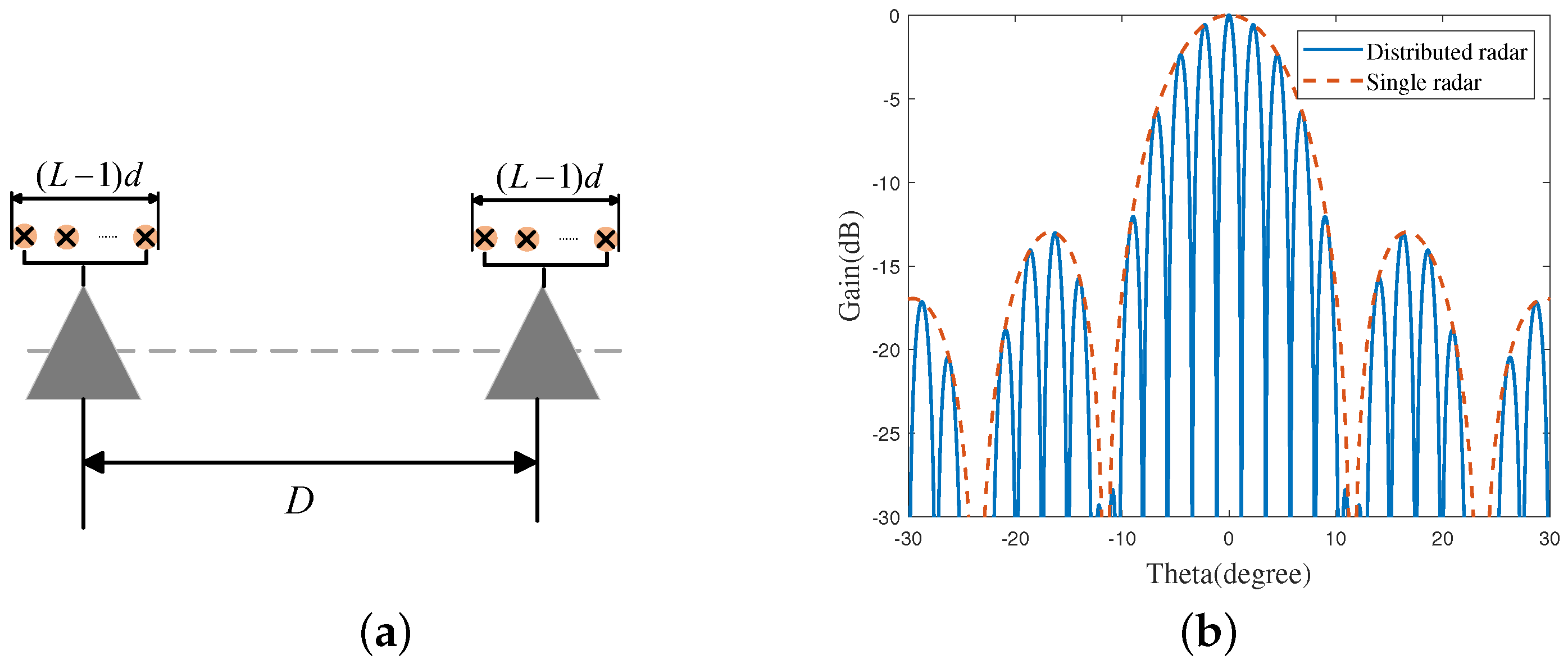
Assume that the distributed array consists of two subarrays, both of which are ULA with L elements. The baseline length between the subarrays is D, the element spacing within the subarrays is d = λ 2 , where λ represents the signal wavelength. The array pattern pointing in the direction of arrival θ 0 can be expressed as
G ( θ ) = cos π D λ ( sin θ sin θ 0 ) sin π 2 M ( sin θ sin θ 0 ) L sin π 2 ( sin θ sin θ 0 ) .
The Figure 3 compares the directional pattern of a distributed array with that of its subarray. As can be seen, the subarray directional pattern overlaps with the envelope of the distributed array directional pattern. This is because the array directional pattern of a distributed array is expressed as a product of two terms: the first term is solely dependent on the subarray spacing D, while the second term represents the directional pattern of the ULA. The beam width of a distributed array radar is significantly narrower than that of a single radar. Therefore, a distributed radar array arrangement can improve angular resolution.

3.2. The Proposed Architecture

Uniformly spaced distributed arrays increase the array aperture by expanding the baseline, effectively improving angular resolution. However, a large number of radar arrays creates redundancy. Reducing hardware consumption while maintaining the same resolution presents a challenge for distributed applications. Coprime arrays, through sparse arrangement, can significantly reduce the number of array elements and eliminate estimation ambiguity through their aperiodic nature. Inspired by this, we incorporate coprime arrangements into distributed array radars, constructing a novel distributed array architecture. This section describes the proposed architecture and parameter configuration method in detail.
As shown in Figure 4, the primary array structure uses a coprime arrangement, with a total of M + N element groups. Each element group has L elements, known as the secondary array structure, and is uniformly arranged. The element spacing in the secondary array structure is d, and the coprime element spacing parameters of the primary array structure are M D and N D . The distance vector for the primary array structure is expressed as P 1 = { m N d + n M d | m , n Z , 0 m M , 0 n N } . The distance vector for the secondary array structure is expressed as P 2 = { l d | l Z , 0 l L } . The distance vector for the entire array structure is expressed as
P = P 1 + P 2 .
In practice, the proposed architecture is primarily controlled by parameters L, D, d, M and N. M and N are set to mutually prime integers. To achieve a common baseline design across spatial scales, the array element spacing must satisfy D > L d . According to the spatial Nyquist theorem, for unambiguous angle measurement, the element spacing d must satisfy d λ 2 .
The core objective of this paper is to propose and validate a novel array architecture (CDA) for the first time, rather than optimizing a specific algorithm. Therefore, a widely applicable, intuitive, and MUSIC algorithm is needed that does not rely on the strict condition that the virtual array must be a physically ULA. Thus, the MUSIC algorithm has high practical value. It is applicable to arrays of any geometry, as long as the steering vector can be computed. This makes it an ideal benchmark for evaluating different array architectures. This paper selects the MUSIC algorithm for angle estimation. The following describes the angle estimation process. First, after receiving the signal, each subarray transmits the array data to the central processing platform. The central processing platform calculates the covariance matrix for all channels. Matrix decomposition is performed on the covariance matrix to obtain the noise subspace. Based on the spatial arrangement of all array elements, a steering vector is calculated. A spatial spectrum is constructed based on the steering vector and the noise subspace. The angle estimation of signal θ ^ is obtained through spectral peak search.

3.3. Discussion on Ambiguity and Grating Lobes

A legitimate concern with any sparse array configuration (including the proposed CDA) is its inherent grating lobe or spatial ambiguity. These ambiguities arise when the large element spacing in the sparse array results in multiple angles satisfying the phase periodicity condition, leading to multiple peaks in the array response of a single sound source. According to Figure 3, the main envelope of the distributed array is determined by the ULA. Therefore, when the ULA satisfies the unambiguity condition ( d λ 2 ), the main envelope has no ambiguous peaks. Although the distributed array’s radiation pattern does not have sidelobes at levels comparable to the main lobe, relatively high sidelobes still exist. These sidelobes originate from the subarray spacing D.
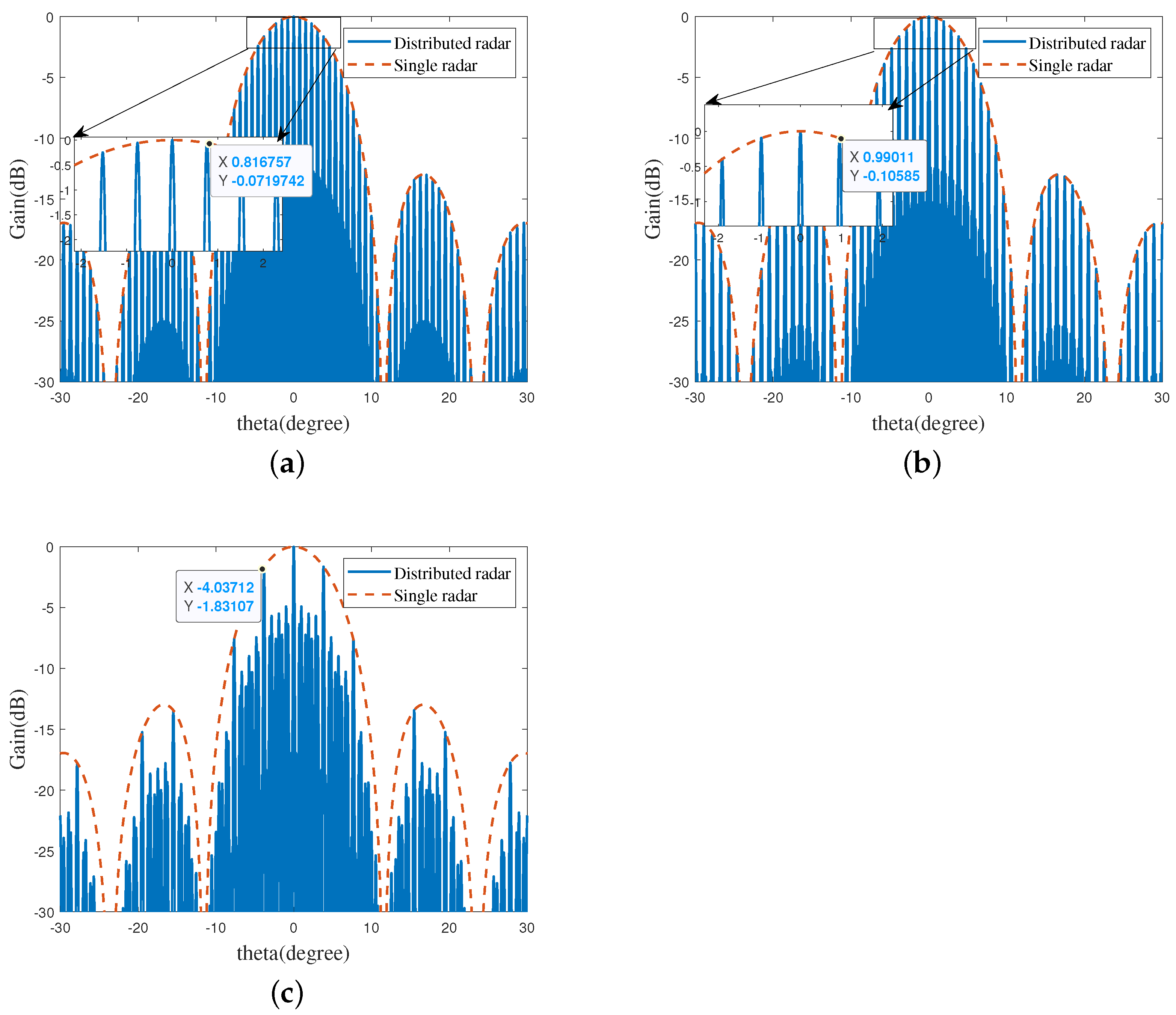
As shown in Figure 5, when D = 30 d , M = 4 and N = 5 , it can be observed that both subarrays in the CDA (spacings M D and N D ) have sidelobes adjacent to the main lobe. However, since their sidelobes do not overlap, these sidelobes are significantly suppressed in the synthesized CDA radiation pattern. Therefore, the key to CDA’s anti-ambiguity lies in its hierarchical two-level structure, which provides a built-in anti-ambiguity mechanism. Specifically, the ULA subarray ensures the unambiguity of the main envelope, and the coprime structure suppresses the level of the sidelobe adjacent to the main lobe.

4. Simulations

In this section, we compare the proposed CDA architecture with a single ULA radar and a UDA radar. We compare the performance of these architectures in terms of angular resolution and mean absolute error (MAE). We also analyze the impact of key system parameters such as snapshot number and radar spacing on angular measurement performance. All results were analyzed using I = 1000 Monte Carlo trials. The MAE of the estimation result is expressed as
MAE = 1 I 1 K k = 1 K i = 1 I θ ^ i , k θ k .

4.1. Estimation Results of the Proposed Structure

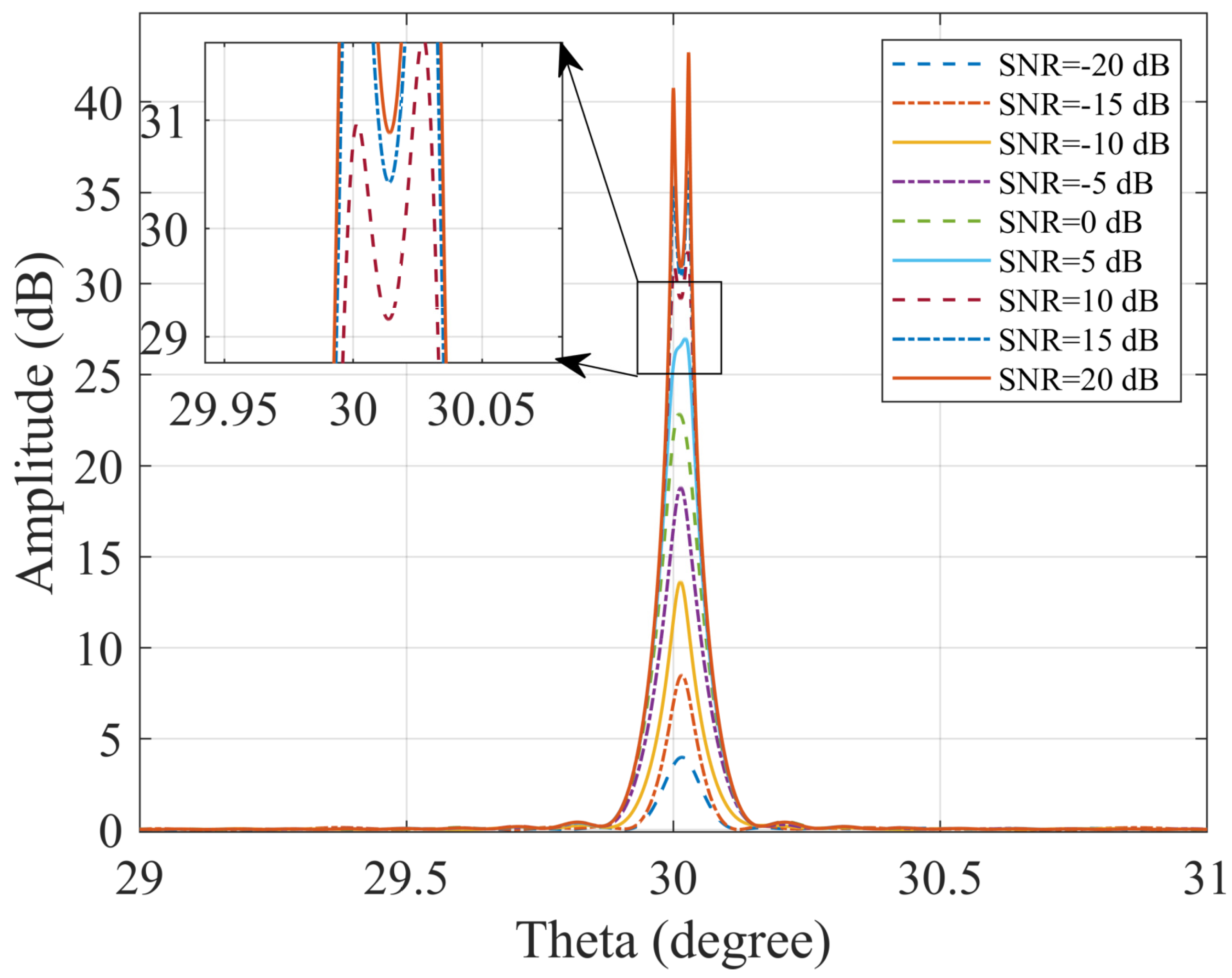
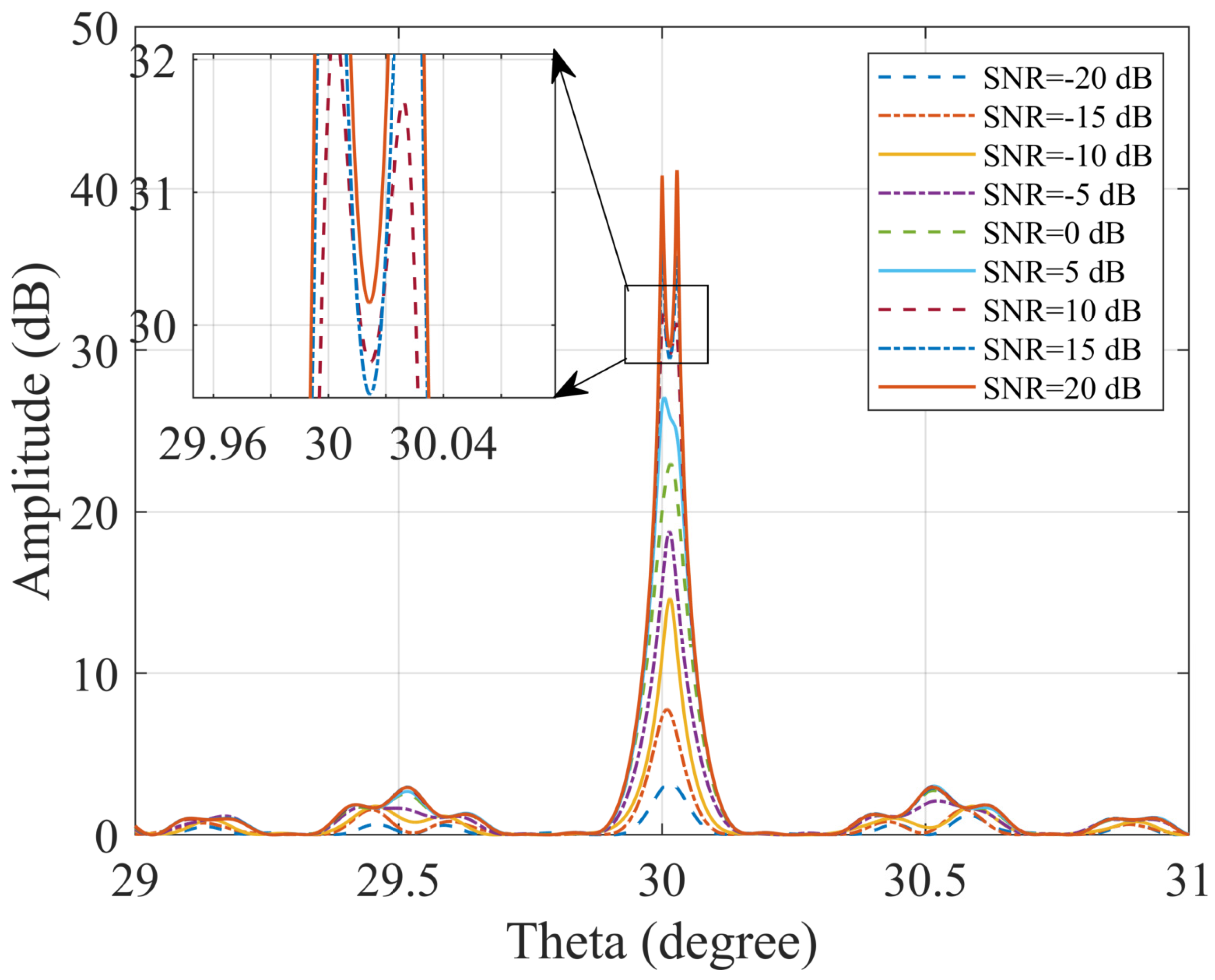
First, we configure the receiving structure parameters. The incident signal frequency is set to f = 10 GHz, so the array element spacing d is set to d = λ 2 = c 2 f = 0.015 m. The coprime numbers M and N are set to 4 and 5 respectively. The number of subarray elements is set to L = 10 . Therefore, the specific radar positions in the CDA are [ 0 D , 4 D , 5 D , 8 D , 10 D , 12 D , 15 D , 16 D , 20 D ] m. The array spacing D = 30 d in UDA is 0.45 m. We simulate a scenario with two targets at 30° and 30.0286 °. The number of snapshots is set to 256, and the SNR level is set to −20∼20 dB. Simulation parameters are listed in Table 1.
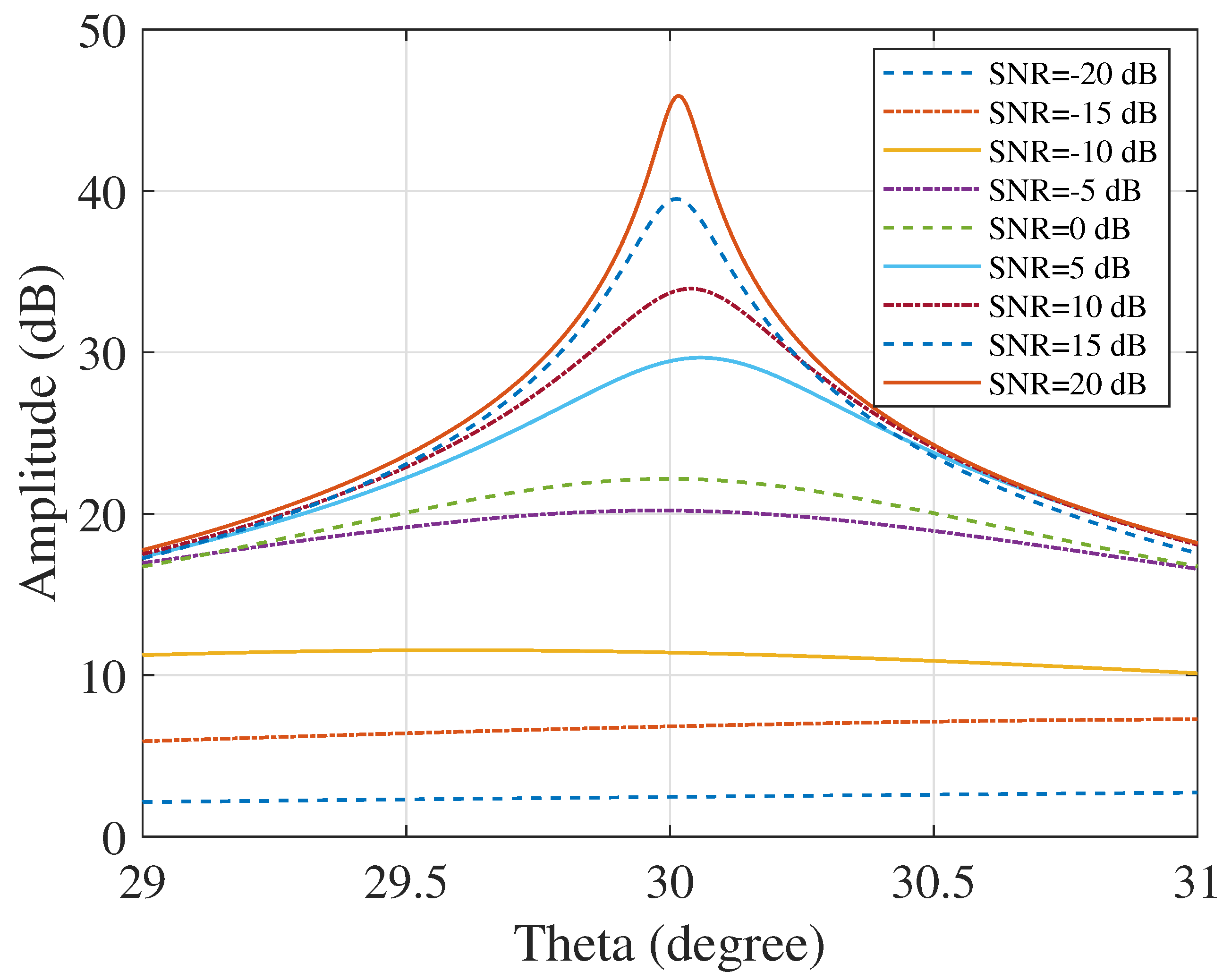
Figure 6 shows that at all SNR levels, spatial spectrum estimation by a single radar completely fails, unable to resolve closely spaced sources. Figure 7 and Figure 8 show that at the same baseline distance, the angle measurement results for the UDA and CDA are essentially identical, demonstrating that the CDA maintains performance while utilizing fewer radars. The spectrum line of the UDA is smoother, and the spectrum line jitter of the CDA is larger, but it is far below the spectrum peak and does not affect the angle measurement results. In this case, the UDA requires 21 radars, while the CDA requires only 9. Furthermore, when the SNR is 10 dB or greater, the algorithm can directly resolve two targets with an angular separation of 0.0286 °. However, when the SNR is below 0 dB, the MUSIC algorithm for both arrays fail to achieve target resolution, but instead generates a target-related spectral peak, which can be used to determine the rough location of the target.

4.2. Simulation of Estimated Performance

In this simulation, we systematically investigate the dependence of the MUSIC algorithm estimation error on the array baseline length for a CDA. Specifically, by fixing the coprime parameters M = 4 and N = 5, we construct a basic architecture consisting of 9 subarrays. Each subarray is configured as a ULA of 10 sensors with a half-wavelength spacing. Using the subarray spacing D and the number of snapshots as key control parameters, the simulation scenario is configured with two equal-power, incoherent, far-field narrowband sources with incident directions of 10 ° and 15°, respectively.
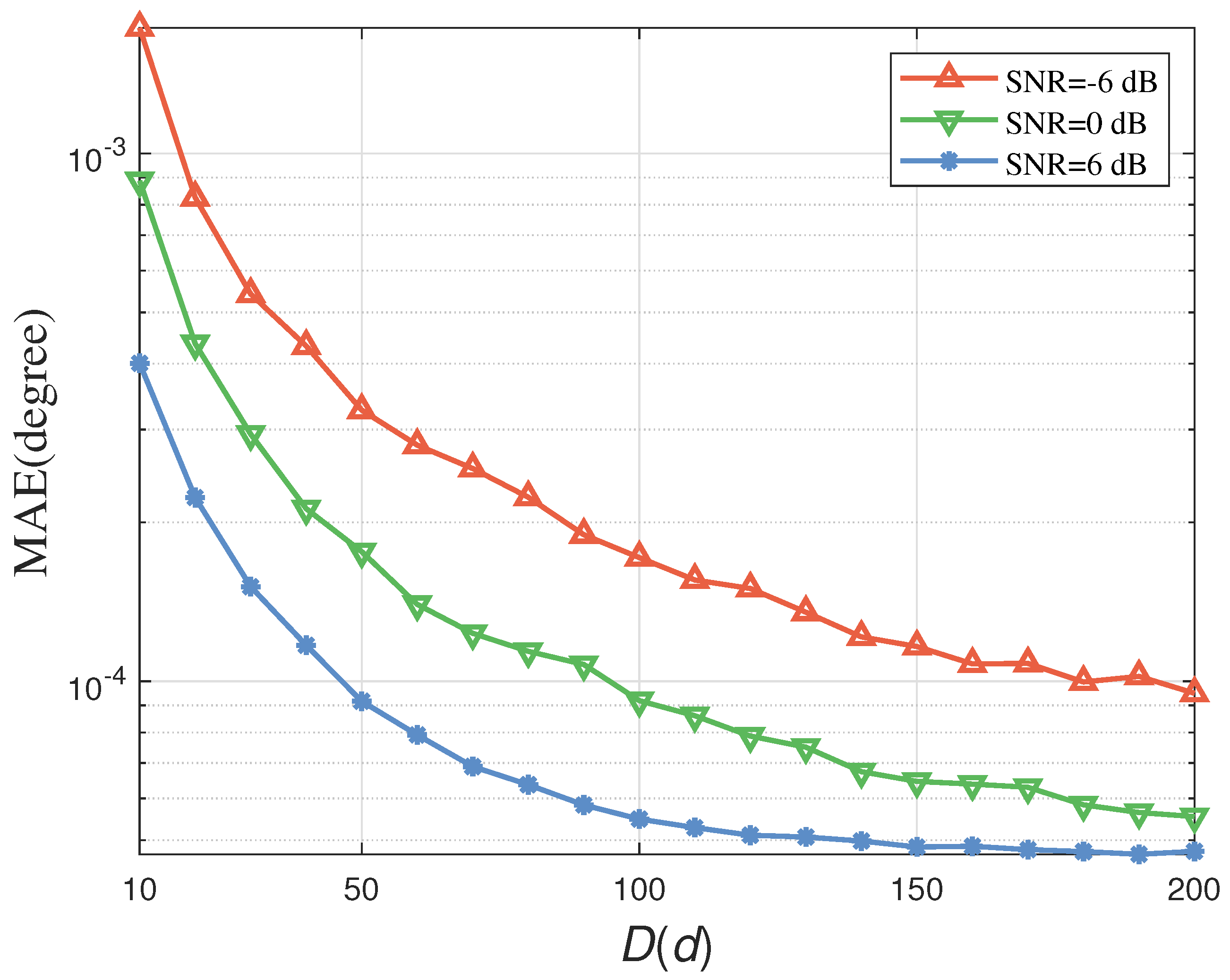
In Experiment 1, the number of snapshots was fixed at 256. The value of D was set to range from 10 d to 200 d and varied systematically in steps of 5 d . This allowed for precise control of the relative distances between subarray centers while maintaining a constant total number of physical sensors at 90, thereby achieving controllable expansion of the array’s physical aperture. The SNR was fixed at 6 , 0, and 6 dB.
The simulation results, illustrated in Figure 9, show a typical three-stage pattern of estimation error variation with increasing baseline length. In the initial stage (D increasing from 10 d to 50 d ), the estimation error rapidly decreases from approximately ( 10 3 )° to around ( 10 4 )°, thanks to the significant compression of the array beam pattern’s mainlobe width and the significant enhancement of the flow pattern vector’s angular resolution. This stage fully demonstrates the fundamental improvement in the algorithm’s resolution achieved by aperture expansion. In the intermediate stage (D increasing from 50 d to 150 d ), the rate of error improvement slowed significantly. At this point, the performance improvement began to be limited by statistical fluctuations caused by the limited number of snapshots and numerical computational precision. When the saturation stage is reached (D exceeds 150 d ), the performance benefit of further increasing the array aperture is negligible and the system has reached its performance limit under the current configuration. The engineering guidance value of this simulation lies in providing a clear parameter optimization range for actual system design. It is recommended that D be selected within the range of 50 d 100 d to achieve the optimal balance between performance and complexity. Simulation results also empirically verify the theoretical basis of the aperture effect in array signal processing, namely the fundamental rule that the estimation error is approximately inversely proportional to the square of the baseline length.
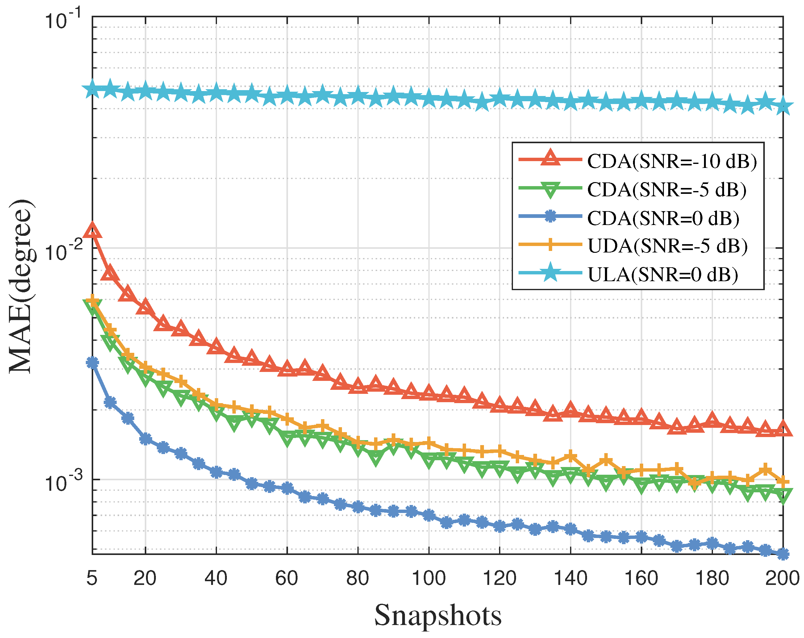
In Experiment 2, D was fixed at 30 d and the SNR was fixed at 10 , 5 , and 0 dB. The number of snapshots was the only independent variable, starting with a very low 5 and gradually increasing to 200 to fully observe the algorithm’s entire process from initial convergence to asymptotic stability. For each given number of snapshots, the estimation performance was quantified by calculating the MAE between the estimated and true angles across all trials.
The simulation results, shown in Figure 10, clearly demonstrate a typical phased convergence behavior. In the initial stage, when the number of snapshots is very small, the MSE is very high and accompanied by large variance due to significant errors in the sample covariance matrix estimation and the extremely unstable eigen decomposition. However, as the number of snapshots increases to the mid-range (20 to 50), the sample covariance matrix gradually approaches the true statistical value, the estimates of the signal and noise subspaces stabilize, and the MAE rapidly decreases, dropping to approximately ( 10 4 )°. When the number of snapshots exceeds 100, the MAE decreases significantly, and the curve gradually flattens, at which point the marginal benefit of performance improvement sharply decreases. The ULA curve is at its highest position, indicating the largest error, and its improvement with increasing snapshot number is limited. This is because its performance bottleneck lies in the physical aperture, not the number of snapshots. It is worth noting that although the number of subarrays in CDA is much smaller than that in UDA, its estimation error convergence trend with the number of snapshots and its final accuracy are highly consistent with those of UDA, which fully demonstrates the hardware efficiency of the CDA architecture.
This entire simulation reveals the fundamental limitations of subspace-based algorithms due to the limited number of snapshots and provides engineering guidance for the minimum number of snapshots required for CDA-based MUSIC algorithms in practical systems. For example, for applications with high real-time requirements, 50 snapshots might be a good compromise, while for high-precision measurement applications, 200 snapshots might be required to ensure sufficient performance convergence.
More advanced algorithms, such as root-based MUSIC or sparse Bayesian learning, generally offer higher accuracy and lower signal-to-noise ratios compared to spectral MUSIC algorithms. However, the core argument and contribution of this paper are based on relative comparisons between different array structures. Crucially, array geometry fundamentally sets a theoretical upper limit on the performance of any unbiased estimator. Our simulation results show that the CDA algorithm consistently outperforms the others significantly. This observed performance gap is primarily attributed to the higher-level geometry of CDA, particularly its larger physical aperture and spatial resolution capabilities, rather than characteristics of the MUSIC algorithm. Therefore, while we acknowledge that absolute performance metrics will vary depending on the algorithm used, we have strong theoretical and empirical reasons to believe that the relative advantage of CDA over traditional arrays can be preserved, or even amplified, through more efficient algorithms.

5. Conclusions

This paper systematically investigates the DOA estimation performance of a novel CDA architecture based on the MUSIC algorithm. Through comprehensive theoretical analysis and numerical simulations, the CDA architecture, which integrates uniform linear subarrays hierarchically within a coprime geometric distributed aperture, demonstrates significant advantages over conventional array architectures. Its core innovation lies in its ability to achieve a significantly larger physical aperture without proportionally increasing the number of physical sensors, thereby achieving global sparsity. Simulation results demonstrate a clear three-phase relationship between estimation error and baseline length: initial rapid improvement, followed by gradual improvement, and ultimately reaching performance saturation. This provides clear engineering guidance for optimizing array design. Furthermore, analysis of the MAE versus snapshot number characterizes the algorithm’s convergence behavior and establishes practical guidelines for selecting the number of snapshots based on the ideal trade-off between estimation accuracy and computational latency. Future work will focus on extending this architecture to two-dimensional geometries, developing robust calibration techniques, and exploring its integration with advanced deep learning-based estimation algorithms. Furthermore, when the subarrays are configured as sparse arrays (nested arrays or coprime arrays), the coprime property between the subarrays may amplify the advantages of the subarrays themselves, which will be the focus of our subsequent research.

Author Contributions

Writing—original draft preparation, M.G.; investigation, M.G., T.M. and Z.S.; writing—review and editing, T.M., Z.L., Y.Z., S.L. and J.W.; project administration, M.G. and S.L.; supervision, M.G.; funding acquisition, M.G. All authors have read and agreed to the published version of the manuscript.

Funding

This work was supported in part by Basic Science Research Project of Jiangsu Province for Colleges and Universities under Grant 25KJD510005, and by the University-level Research Project of Nanjing University of Science and Technology ZiJin College under Grant 2025ZRKX0401009.

Institutional Review Board Statement

Not applicable.

Informed Consent Statement

Not applicable.

Data Availability Statement

The original contributions presented in this study are included in the article. Further inquiries can be directed to the corresponding author.

Acknowledgments

The authors thank the reviewers for their great help with the article during its review progress.

Conflicts of Interest

The authors declare no conflicts of interest.

References

  1. Liu, W.; Haardt, M.; Greco, M.S.; Mecklenbräuker, C.F.; Willett, P. Twenty-Five Years of Sensor Array and Multichannel Signal Processing: A review of progress to date and potential research directions. IEEE Signal Process. Mag. 2023, 40, 80–91. [Google Scholar] [CrossRef]
  2. Tsui, J.; Stephens, J. Digital microwave receiver technology. IEEE Trans. Microw. Theory Tech. 2002, 50, 699–705. [Google Scholar] [CrossRef]
  3. Dang, X.; Liu, H.; Yan, J. Robust Elliptic Positioning via Sparse Regularization and ADMM for a Distributed MIMO Radar in the Presence of Outliers. IEEE Signal Process. Lett. 2024, 31, 2110–2114. [Google Scholar] [CrossRef]
  4. Shi, J.; Wen, F.; Liu, T. Nested MIMO Radar: Coarrays, Tensor Modeling, and Angle Estimation. IEEE Trans. Aerosp. Electron. Syst. 2021, 57, 573–585. [Google Scholar] [CrossRef]
  5. Tong, X.; Hu, Y.; Deng, Z.; Hu, E. Accelerating Broadband DOA Estimation: A Real-Valued and Coherent Sparse Bayesian Approach for 5G Sensing. Electronics 2025, 14, 3174. [Google Scholar] [CrossRef]
  6. Tong, X.; Chen, Y.; Deng, Z.; Hu, E. An Off-Grid DOA Estimation Method via Fast Variational Sparse Bayesian Learning. Electronics 2025, 14, 2781. [Google Scholar] [CrossRef]
  7. Zheng, H.; Zheng, G.; Song, Y.; Xiao, L.; Qin, C. Direction-of-Arrival Estimation with Discrete Fourier Transform and Deep Feature Fusion. Electronics 2025, 14, 2449. [Google Scholar] [CrossRef]
  8. Schmidt, R. Multiple emitter location and signal parameter estimation. IEEE Trans. Antennas Propag. 1986, 34, 276–280. [Google Scholar] [CrossRef]
  9. Roy, R.; Kailath, T. ESPRIT-estimation of signal parameters via rotational invariance techniques. IEEE Trans. Acoust. Speech Signal Process. 1989, 37, 984–995. [Google Scholar] [CrossRef]
  10. Florio, A.; Coviello, G.; Talarico, C.; Avitabile, G. Adaptive DDS-PLL Beamsteering Architecture based on Real-Time Angle-of-Arrival Estimation. In Proceedings of the 2024 IEEE 67th International Midwest Symposium on Circuits and Systems (MWSCAS), Springfield, MA, USA, 11–14 August 2024; pp. 628–631. [Google Scholar] [CrossRef]
  11. Avitabile, G.; Man, K.L.; Talarico, C. DDS-PLL Architecture for Adaptive Beam Steering. In Proceedings of the 2024 21st International SoC Design Conference (ISOCC), Sapporo, Japan, 19–22 August 2024; pp. 205–206. [Google Scholar] [CrossRef]
  12. Florio, A.; Coviello, G.; Talarico, C.; Avitabile, G. Adaptive Beamsteering Architecture Based on AoA Estimation with Phase Shift on LO-Path for 5G NR. In Proceedings of the 2024 9th International Conference on Smart and Sustainable Technologies (SpliTech), Bol and Split, Croatia, 25–28 June 2024; pp. 1–5. [Google Scholar] [CrossRef]
  13. Florio, A.; Avitabile, G. Characterization of a Multisource Angle of Arrival Estimation Technique based on Phase Interferometry. In Proceedings of the 2022 18th International Conference on Synthesis, Modeling, Analysis and Simulation Methods and Applications to Circuit Design (SMACD), Villasimius, Italy, 12–15 June 2022; pp. 1–4. [Google Scholar] [CrossRef]
  14. Florio, A.; Avitabile, G.; Coviello, G. Multiple Source Angle of Arrival Estimation Through Phase Interferometry. IEEE Trans. Circuits Syst. II Express Briefs 2022, 69, 674–678. [Google Scholar] [CrossRef]
  15. Florio, A.; Avitabile, G.; Talarico, C.; Coviello, G. A Reconfigurable Full-Digital Architecture for Angle of Arrival Estimation. IEEE Trans. Circuits Syst. I Regul. Pap. 2024, 71, 1443–1455. [Google Scholar] [CrossRef]
  16. Zhang, S.; Xue, C.; Luo, J.; Wen, B.; Han, Y.; Sheng, W. Sparse Array Wideband Beamforming Based on Covariance Matrix Reconstruction and Neural Network. IEEE Trans. Veh. Technol. 2025, 1–13. [Google Scholar] [CrossRef]
  17. Zhang, S.; Gu, Q.; Ma, X.; Sheng, W.; Kirubarajan, T. A data alternating extraction general structure and its algorithms for adaptive space–time wideband beamforming. Digit. Signal Process. 2022, 126, 103478. [Google Scholar] [CrossRef]
  18. Wang, X.; Zhai, W.; Wang, X.; Amin, M.; Zoubir, A. Wideband Near-Field Integrated Sensing and Communications: A hybrid precoding perspective. IEEE Signal Process. Mag. 2025, 42, 88–105. [Google Scholar] [CrossRef]
  19. Wang, X.; Huang, J.; Wang, X.; Huang, T.; Amin, M. Optimal Sparse Array Design for Airborne Weather Radar with Integrated Communications. IEEE Trans. Aerosp. Electron. Syst. 2025, 61, 4238–4254. [Google Scholar] [CrossRef]
  20. Chen, H.; Wang, W.; Liu, W.; Tian, Y.; Wang, G. An Exact Near-Field Model Based Localization for Bistatic MIMO Radar with COLD Arrays. IEEE Trans. Veh. Technol. 2023, 72, 16021–16030. [Google Scholar] [CrossRef]
  21. Wang, X.; Guo, Y.; Wen, F.; He, J.; Truong, T.K. EMVS-MIMO Radar with Sparse Rx Geometry: Tensor Modeling and 2-D Direction Finding. IEEE Trans. Aerosp. Electron. Syst. 2023, 59, 8062–8075. [Google Scholar] [CrossRef]
  22. Dong, X.; Zhao, J.; Sun, M.; Zhang, X.; Wang, Y. A Modified Generalized Labeled Multi-Bernoulli Filtering for Multi-Source DOA Tracking with Coprime Array. IEEE Trans. Wirel. Commun. 2023, 22, 9424–9437. [Google Scholar] [CrossRef]
  23. Luo, J.; Zhu, H.; Zhang, S.; Han, Y.; Sheng, W. Low Complexity Neural Network Guided Robust Space-time Adaptive Wideband Beamforming. IEEE Trans. Aerosp. Electron. Syst. 2025, 1–15. [Google Scholar] [CrossRef]
  24. Chen, H.; Guo, H.; Liu, W.; Shen, Q.; Wang, G.; So, H.C. Fourth-Order Sparse Array Design From a Sum-Difference Co-Array Perspective. IEEE Trans. Signal Process. 2025, 73, 2243–2254. [Google Scholar] [CrossRef]
  25. Moffet, A. Minimum-redundancy linear arrays. IEEE Trans. Antennas Propag. 1968, 16, 172–175. [Google Scholar] [CrossRef]
  26. Vaidyanathan, P.P.; Pal, P. Sparse sensing with coprime arrays. In Proceedings of the 2010 Conference Record of the Forty Fourth Asilomar Conference on Signals, Systems and Computers, Pacific Grove, CA, USA, 7–10 November 2010; pp. 1405–1409. [Google Scholar] [CrossRef]
  27. Wang, Q.; Xue, C.; Zhang, S.; Zhang, R.; Sheng, W. Design of Extensible Structured Interferometric Array Utilizing the “Coarray” Concept. Remote Sens. 2023, 15, 1934. [Google Scholar] [CrossRef]
  28. Pal, P.; Vaidyanathan, P.P. Nested Arrays: A Novel Approach to Array Processing with Enhanced Degrees of Freedom. IEEE Trans. Signal Process. 2010, 58, 4167–4181. [Google Scholar] [CrossRef]
  29. Malioutov, D.; Cetin, M.; Willsky, A. A sparse signal reconstruction perspective for source localization with sensor arrays. IEEE Trans. Signal Process. 2005, 53, 3010–3022. [Google Scholar] [CrossRef]
  30. Chi, Y.; Scharf, L.L.; Pezeshki, A.; Calderbank, A.R. Sensitivity to Basis Mismatch in Compressed Sensing. IEEE Trans. Signal Process. 2011, 59, 2182–2195. [Google Scholar] [CrossRef]
  31. Wong, K.; Zoltowski, M. Direction-finding with sparse rectangular dual-size spatial invariance array. IEEE Trans. Aerosp. Electron. Syst. 1998, 34, 1320–1336. [Google Scholar] [CrossRef]
  32. Liao, Y.; Zhao, R.; Liu, H. DOA Estimation Method with the Distributed Nested Array. In Proceedings of the 2018 10th International Conference on Wireless Communications and Signal Processing (WCSP), Hangzhou, China, 18–20 October 2018; pp. 1–6. [Google Scholar] [CrossRef]
  33. Liao, Y.; Lin, Y.; Zhao, R. 2D-DOA Estimation Using L-shaped Distributed Augmented Nested Array. In Proceedings of the 2021 13th International Conference on Wireless Communications and Signal Processing (WCSP), Changsha, China, 20–22 October 2021; pp. 1–7. [Google Scholar] [CrossRef]
  34. Vasylyshyn, V. Closed-form DOA estimation with multiscale unitary ESPRIT algorithm. In Proceedings of the First European Radar Conference (EURAD 2004), Amsterdam, The Netherlands, 11–15 October 2004; pp. 317–320. [Google Scholar]
  35. Yu, W.; He, P.; Cui, A.; Wang, H.; Zhou, H.; Xu, Z. DOA Estimation Ambiguity Resolution Method for Near Field Distributed Array. In Proceedings of the 2021 6th International Conference on Intelligent Computing and Signal Processing (ICSP), Xi’an, China, 9–11 April 2021; pp. 870–875. [Google Scholar] [CrossRef]
  36. Chowdhury, M.W.T.S.; Zhang, Y.D. Direction-of-Arrival Estimation Exploiting Distributed Sparse Arrays. In Proceedings of the 2021 55th Asilomar Conference on Signals, Systems, and Computers, Pacific Grove, CA, USA, 31 October–3 November 2021; pp. 231–235. [Google Scholar] [CrossRef]
  37. Xie, Q.; Wang, Z.; Wen, F.; He, J.; Truong, T.K. Coarray Tensor Train Decomposition for Bistatic MIMO Radar with Uniform Planar Array. IEEE Trans. Antennas Propag. 2025, 73, 5310–5323. [Google Scholar] [CrossRef]
  38. Xie, Q.; Shi, J.; Wen, F.; Zheng, Z. Higher-order tensor decomposition for 2D-DOD and 2D-DOA estimation in bistatic MIMO radar. Signal Process. 2026, 238, 110196. [Google Scholar] [CrossRef]
  39. Pavel, S.R.; Chowdhury, M.W.T.S.; Zhang, Y.D.; Shen, D.; Chen, G. Machine Learning-Based Direction-of-Arrival Estimation Exploiting Distributed Sparse Arrays. In Proceedings of the 2021 55th Asilomar Conference on Signals, Systems, and Computers, Pacific Grove, CA, USA, 31 October–3 November 2021; pp. 241–245. [Google Scholar] [CrossRef]
  40. Zhang, S.; Thiyagalingam, J.; Sheng, W.; Kirubarajan, T.; Ma, X. Low-complexity adaptive broadband beamforming based on the non-uniform decomposition method. Signal Process. 2018, 151, 66–75. [Google Scholar] [CrossRef]
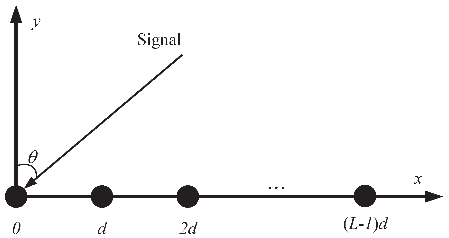
Figure 1. The schematic diagram of a ULA.
Electronics 14 04562 g001
Figure 2. The demonstration of the impact of angle estimation error on spatial positioning.
Electronics 14 04562 g002
Figure 3. (a) The distributed array structure. (b) The beam pattern of the distributed array.
Electronics 14 04562 g003
Figure 4. The proposed Coprime distributed aaarray.
Electronics 14 04562 g004
Figure 5. (a) The beam pattern of the UDA with subarray spacing of N D . (b) The beam pattern of the UDA with subarray spacing of M D . (c) The beam pattern of the CDA.
Electronics 14 04562 g005
Figure 6. The spatial spectrum of the ULA.
Electronics 14 04562 g006
Figure 7. The spatial spectrum of the UDA.
Electronics 14 04562 g007
Figure 8. The spatial spectrum of the CDA.
Electronics 14 04562 g008
Figure 9. MAE with various baseline length.
Electronics 14 04562 g009
Figure 10. MAE with various snapshots.
Electronics 14 04562 g010
Table 1. Simulation parameters.
ULAUDACDA
Element spacing (d) 0.015 m 0.015 m 0.015 m
Number of arrays1219
Number of elements per subarray (L)101010
Subarray spacing (D) 0.45 m 0.45 m
Array aperture 0.135 m9 m9 m
Frequency of the incident signal (f)10 GHz10 GHz10 GHz
Target angle interval 0.0286 ° 0.0286 ° 0.0286 °
SNR−20∼20 dB−20∼20 dB−20∼20 dB
Spatial spectrum grid 0.0002 ° 0.0002 ° 0.0002 °
Number of snapshots256256256
Disclaimer/Publisher’s Note: The statements, opinions and data contained in all publications are solely those of the individual author(s) and contributor(s) and not of MDPI and/or the editor(s). MDPI and/or the editor(s) disclaim responsibility for any injury to people or property resulting from any ideas, methods, instructions or products referred to in the content.