Article

Robust Direct Multi-Camera SLAM in Challenging Scenarios

National Key Laboratory of ATR, College of Electronic Science and Technology, National University of Defense Technology, Changsha 410073, China
*
Author to whom correspondence should be addressed.
Electronics 2025, 14(23), 4556; https://doi.org/10.3390/electronics14234556
Submission received: 10 September 2025 / Revised: 19 November 2025 / Accepted: 19 November 2025 / Published: 21 November 2025

Abstract

Traditional monocular and stereo visual SLAM systems often fail to operate stably in complex unstructured environments (e.g., weakly textured or repetitively textured scenes) due to feature scarcity from their limited fields of view. In contrast, multi-camera systems can effectively overcome the perceptual limitations of monocular or stereo setups by providing broader field-of-view coverage. However, most existing multi-camera visual SLAM systems are primarily feature-based and thus still constrained by the inherent limitations of feature extraction in such environments. To address this issue, a multi-camera visual SLAM framework based on the direct method is proposed. In the front-end, a detector-free matcher named Efficient LoFTR is incorporated, enabling pose estimation through dense pixel associations to improve localization accuracy and robustness. In the back-end, geometric constraints among multiple cameras are integrated, and system localization accuracy is further improved through a joint optimization process. Through extensive experiments on public datasets and a self-built simulation dataset, the proposed method achieves superior performance over state-of-the-art approaches regarding localization accuracy, trajectory completeness, and environmental adaptability, thereby validating its high robustness in complex unstructured environments.

1. Introduction

Robotics is rapidly expanding from highly structured industrial environments (e.g., factories and warehouses) to complex, dynamic, and unpredictable unstructured field environments, representing a critical frontier in developing autonomous systems. In key application domains such as agricultural automation, forestry exploration, and search and rescue [1], robots are required to perform tasks without access to pre-constructed maps or stable infrastructure. In such scenarios, conventional navigation tools such as the Global Positioning System (GPS) often suffer severe reliability issues. For instance, dense forest canopies may block satellite signals, while complex terrains can cause signal interruptions or multipath effects.
To address the aforementioned challenges, visual simultaneous localization and mapping (vSLAM) has emerged as an effective solution and has become one of the core technologies for robotic pose estimation [2]. This technique employs visual sensors as the primary information source, offering advantages such as low hardware cost, lightweight, and low power consumption. Compared with navigation approaches that rely on external electromagnetic signals (e.g., GPS), vSLAM provides a passive perception modality by directly capturing optical information from the environment (e.g., rich texture details and semantic cues), without depending on any external signal sources. This establishes the essential data foundation for enabling robust autonomous localization and mapping in scenarios lacking reliable infrastructure or prior maps [3].
However, to fully exploit the advantages of visual SLAM in complex outdoor environments, a fundamental challenge lies in achieving robust and accurate pose estimation in scenarios that lack prominent geometric structures (unstructured) or exhibit sparse surface textures (weakly textured). Such environments are typically characterized by the absence of clear geometric features (e.g., distinct lines and planar structures) or large regions of repetitive patterns and sparse texture details, as often observed in natural scenes such as open fields, dense forest canopies, and barren rocky slopes.
Compared with monocular or stereo visual SLAM systems, multi-camera visual SLAM benefits from a significantly larger field of view, which allows the system to capture richer environmental information [2] and thereby enhances its robustness in complex unstructured environments. However, most existing multi-camera SLAM systems are built using feature-based methods. When confronted with complex, unstructured environments, multi-camera SLAM still cannot overcome the technical limitations inherent to feature-based approaches. To further improve the robustness and localization accuracy of multi-camera visual SLAM in complex unstructured environments, a multi-camera visual SLAM framework based on direct methods is proposed in this paper.
The main contributions of this work can be summarized as follows, forming a complete SLAM solution tailored for complex unstructured environments:
  • A multi-camera visual SLAM framework based on direct methods is designed and implemented to maintain high localization accuracy and robustness in weakly textured and unstructured environments, where visual information is degraded.
  • A robust visual front-end integrating deep learning and the direct method is proposed. This front-end first leverages the semi-dense matching capability of Efficient LoFTR to robustly estimate the inter-frame initial poses, fundamentally overcoming the initialization failures of traditional direct methods that depend on the constant velocity model in cases of non-smooth motion or weak textures. Subsequently, this high-precision initialization successfully guides the direct method to perform photometric error optimization, thereby achieving reliable and accurate camera pose estimation even in challenging scenarios.
  • A multi-camera joint optimization back-end is designed in which the inter-frame photometric error constraints and the inter-camera rigid geometric consistency constraints are tightly coupled. By effectively exploiting redundant observations from multiple cameras, the system refines poses online and further improves overall localization accuracy.
  • Extensive experimental evaluations are conducted on public datasets and a self-constructed simulation dataset, with the results demonstrating the superior robustness and localization accuracy of the proposed method.

2. Related Work

2.1. Multi-Camera Visual SLAM

Due to their wide field of view, multi-camera configurations provide rich visual information and have been demonstrated to significantly enhance the robustness of SLAM systems [4]. Initially, Ragab et al. conducted a preliminary attempt at multi-camera visual SLAM by employing an extended Kalman filter to fuse the motion information from two sets of stereo cameras [5]. Subsequently, the MCPTAM algorithm proposed by Harmat and Tribou became a classical multi-camera visual SLAM approach [6], innovatively introducing the concept of multiple keyframes and laying an important foundation for subsequent research.
Multi-camera SLAM systems commonly adopt indirect methods, primarily due to the inherent advantages of their extracted feature points in establishing data association among multiple cameras. For instance, Yang et al. [7] employed ORB feature points to propose a general SLAM framework capable of handling asynchronous camera observations. Zhang et al. [8] improved the accuracy of visual-inertial odometry by utilizing co-visible features across multiple cameras. Harmat et al. proposed BundledSLAM [9], which extends ORB-SLAM2 [10] to multi-camera setups to achieve higher precision. Yang et al. designed an omnidirectional loop detection method in MCOV-SLAM [11] to maximize the advantage of omnidirectional perception from multiple cameras. In recent years, deep learning techniques have also been introduced to enhance the performance of multi-camera visual SLAM systems. Pan et al. [12] leveraged deep learning based on MCOV-SLAM for semantic mapping, achieving higher-level target association in MCOO-SLAM. Meanwhile, Yu et al. [2] proposed MCVO, which utilizes the robustness of SuperPoint to address the scale estimation challenge in multi-camera systems with arbitrary configurations.
Although these approaches have achieved remarkable success in multi-camera configurations, they remain constrained by a fundamental limitation of indirect methods: their performance strongly relies on the critical assumption that the environment contains sufficient feature points that can be stably detected and reliably distinguished. In the unstructured or weakly textured environments considered in this work, however, this assumption often does not hold [13]. For example, in dense forest scenes, feature points extracted by detectors are often unstable and lack distinctiveness, which leads to ambiguous or incorrect matches, ultimately causing severe pose drift or even tracking failure.
To address this challenge, direct methods provide a fundamentally different paradigm for visual SLAM. Instead of relying on feature extraction and matching, direct methods estimate camera motion by minimizing photometric errors over corresponding pixel patches observed from different viewpoints [14]. They can exploit gradient information across the entire image, including edges and relatively smooth regions, rather than being restricted to sparse feature points. These characteristics enable direct methods to handle weakly textured and unstructured environments effectively. However, the key nonlinear optimization process also introduces new issues: direct methods are susceptible to the accuracy of the initial pose [15]. Since the optimization algorithm linearizes the error function only near the initial estimate, large deviations from the ground truth can easily cause the solution to fall into local minima or even diverge completely, ultimately resulting in tracking failure.
In summary, the current field of multi-camera visual SLAM still faces key challenges: mainstream indirect methods suffer from a lack of robustness in weakly textured or unstructured environments due to their reliance on feature points, while direct methods, though more suitable for such scenarios, exhibit inherent flaws in their strong sensitivity to initial pose.

2.2. Deep Feature Matching

In recent years, the breakthrough progress in deep learning-based feature matching has provided an ideal tool to address the aforementioned challenges. Presently, deep learning-driven feature matching methods have gradually replaced traditional handcrafted features and are mainly categorized into two paradigms: detector-based and detector-free approaches.
Detector-based methods follow the classical three-stage pipeline of “detection–description–matching”, which was originally defined by handcrafted features such as SIFT, SURF, and ORB. With the development of deep learning, researchers have started to enhance or replace components of this pipeline with learning modules. For instance, methods such as HardNet have learned descriptors with stronger discriminative power than SIFT, while SuperPoint and D2-Net jointly learn more repeatable keypoint detectors and descriptors. Among these, the most significant advances come from learning-based matchers such as SuperGlue, which leverages graph neural networks and attention mechanisms to perform global contextual reasoning over keypoints and descriptors from the previous stage, effectively rejecting outliers and significantly improving both precision and recall of matches [16]. However, all detector-based methods share a fundamental limitation: their performance is bounded by the initial keypoint detection stage. In unstructured, weakly textured, or repetitively textured scenes, if the detector fails to find sufficient and repeatable interest points, the entire matching pipeline collapses.
To overcome this bottleneck, detector-free methods have emerged, completely discarding the explicit keypoint detection step and directly establishing dense pixel-level correspondences between image pairs. LoFTR [17], as a pioneering work in this direction, first introduced the Transformer architecture into feature matching. By employing interleaved self-attention and cross-attention layers, it endowed the model with a global receptive field, enabling the exploitation of global contextual information to establish feature correspondences and produce highly robust matching results in weakly textured or even textureless regions. The success of LoFTR has inspired many subsequent works, such as Efficient LoFTR [18] and Matchformer [19], which continuously improve both efficiency and accuracy, further demonstrating the great potential of this research direction.
Nevertheless, despite the remarkable progress of detector-free methods, integrating them directly into classical geometry-based SLAM systems remains challenging. State-of-the-art SLAM back-ends rely on global bundle adjustment for optimization, whose mathematical framework requires long-term and consistent feature tracks—sequences of 2D observations of the same 3D point across multiple camera views. While detector-free matchers can generate highly accurate sub-pixel correspondences for image pairs, these correspondences are essentially instantaneous relations that only exist between specific image pairs and lack persistent keypoint entities that can be tracked over time. As a result, when applied to image sequences, the feature tracks formed by these correspondences are often fragmented and inconsistent, making their data structures incompatible with the input requirements of bundle adjustment optimizers. This “multi-view inconsistency” problem has been widely recognized. For example, in a recent study, Detector-Free SfM (DFSfM) [20] was explicitly proposed to address this challenge. These approaches introduce complex post-processing steps, such as correspondence quantization or iterative multi-view refinement, to resolve the issue, but inevitably increase system complexity.
In summary, due to the “multi-view inconsistency” problem, integrating detector-free matchers into conventional feature-based SLAM back-ends remains challenging. This paper does not attempt to resolve such inconsistency by constructing long-term feature tracks but instead circumvents the issue through a novel architectural design. A hybrid framework is proposed, which fuses a detector-free matcher with a direct visual SLAM front-end. In this framework, the detector-free matcher (Efficient LoFTR) is used solely to compute highly robust inter-frame relative pose initialization (see Section 3.2). The estimated pose is then adopted as the initial value for the direct method, which optimizes poses by minimizing photometric error rather than tracking discrete feature points.
This integration exploits the complementary advantages of both paradigms: the robustness of detector-free matchers in weakly textured environments mitigates the inherent initialization sensitivity of direct methods, while the formulation of the direct method eliminates the need for persistent feature tracks that detector-free matchers cannot reliably provide. Based on this insight, a novel multi-camera visual SLAM framework based on direct methods is proposed.

3. Materials and Methods

3.1. System Overview

The proposed multi-camera visual SLAM framework is illustrated in Figure 1. The main input consists of synchronized multi-camera image sequences, where multiple cameras are rigidly mounted and pre-calibrated with known intrinsic and extrinsic parameters. The output is the six-degree-of-freedom (6-DoF) camera poses. The processing pipeline mainly includes three components: efficient LoFTR-based feature matching, camera pose estimation, and multi-camera bundle adjustment.
The system front-end processes the synchronized multi-camera image sequences. First, the Efficient LoFTR module extracts semi-dense correspondences for selected image pairs. Then, during the camera pose estimation stage, the geometric pose estimation submodule computes the initial relative pose using these correspondences. Finally, this initial pose is fed into the photometric error minimization submodule, which refines the camera pose through optimization.
To further clarify the system’s operational logic, the detailed control flow is illustrated in Figure 2. The system operates in a loop processing incoming multi-camera frames. As shown in the flowchart, after the initial pose is refined, a keyframe decision module evaluates the current frame based on the tracking quality. If the frame is determined to be a non-keyframe, the system directly outputs the current pose and proceeds to the next frame. Conversely, if a new keyframe is generated, the multi-camera joint optimization back-end module is triggered. This module, based on the front-end estimated poses, constructs a unified objective function coupling photometric error and geometric consistency constraints. The optimal system poses are obtained through nonlinear optimization and output as the final results.

3.2. Robust Camera Pose Estimation

This section provides a detailed discussion of the deep learning-driven visual front-end in our framework. The front-end is designed to ensure robust pose estimation in unstructured or weakly textured environments. Traditional direct methods, such as DSO [6], are theoretically suitable for weakly textured environments where feature-based approaches fail, but their performance highly depends on the quality of motion initialization. In practice, these systems usually adopt a constant velocity motion model to predict the pose of new frames [21]. This assumption is generally valid in structured environments with smooth motion, but it fails easily in unstructured and weakly textured settings. For example, in scenes with grasslands and forests, strong visual repetitiveness and ambiguity cause the cost surface of the photometric error function to contain numerous spurious local minima. In such cases, once the constant velocity model provides a poor initial estimate due to non-smooth robot motion, the gradient descent-based optimization process is prone to being trapped in these local minima or failing to converge, eventually leading to tracking failure.
To fundamentally address this issue, a novel initial pose estimation strategy is introduced by replacing the fragile constant velocity model with a robust, data-driven geometric pose estimation. The superior matching capability of Efficient LoFTR [18] is leveraged to achieve this goal, whose main advantage lies in its ability to provide highly accurate semi-dense correspondences even in degraded visual regions such as weak textures and repetitive patterns. The network first employs a lightweight convolutional backbone to extract multi-scale feature maps from an image pair. Then, through an efficient aggregation attention mechanism, it transforms and enhances coarse-grained features while retaining a global receptive field. Next, mutual nearest-neighbor search is applied to establish high-confidence initial correspondences between the transformed feature maps. Finally, under the supervision of a two-stage correlation layer, these coarse correspondences are refined to sub-pixel accuracy.
To estimate the pose T j W relative to the local map M = P 1 , , P N , the initial correspondence set M is obtained from Efficient LoFTR with confidence c above the threshold τ conf (as in Equation (1)), and the essential matrix E between the two frames is robustly estimated using the eight-point algorithm with RANSAC. The threshold τ conf is set to 0.5, which we found to balance the goals of rejecting low-confidence outliers while preserving a sufficient number of correspondences for the RANSAC estimator. Furthermore, singular value decomposition (SVD) is performed on E to recover the relative pose T j i n i t between the cameras as the initialization.
M = { ( p i , q i ) c i > τ conf } i = 1 M
Once the initial pose T j i n i t is obtained, points in the local map are projected into the target frame I j using T j i n i t , and the photometric error function is defined as
E p = u k N u w k r k 2 x j = u k N u w k I i u k b i e a i e a j I j u k b j 2
where the weighted sum of squared differences (SSD) within a small pixel neighborhood N u is used to measure the photometric error of a point from the reference frame I i relative to the target frame I j . w k is a gradient-based weight coefficient; a and b are affine brightness correction factors; u k is the reprojected position of point u k based on the inverse depth d p . It is given by
u k = π ( R π 1 ( u k , d p ) + t )
where π ( ) denotes the projection function that projects a 3D point onto the 2D image plane, R is the rotation matrix, π 1 ( ) represents the inverse projection function that maps a 2D pixel coordinate u k and depth d p back into 3D space, and t is the translation vector. w k = w k g w k r is a combined weight factor [21]:
w k g = c w 2 c w 2 + I i [ u k ] 2 2 , w k r = ν + 1 ν + ( r k σ k ) 2
where w k g penalizes high-gradient pixels, while w k r is a robust weight assuming the residuals of the sparse model follow a t -distribution with degrees of freedom ν . A gradient-based outlier rejection method is employed: if r k 2 > | | I i [ u k ] | | 2 2 , the observation is considered invalid and removed from the optimization.
E track = I i K p P i j E p
The total error of local tracking is given in Equation (5), where P i j denotes the set of points from keyframe K i visible in I j .

3.3. Multi-Camera Joint Bundle Adjustment

This section presents our proposed sliding-window bundle adjustment framework, which jointly optimizes the poses of the multi-camera platform, the inverse depths of 3D points, and photometric parameters.
The proposed method is structured in two stages. To fully exploit the rigidity of the multi-camera rig, an inter-camera geometric consistency error term is introduced, which enforces that at any time within the sliding window, the relative poses between cameras are kept consistent with their pre-calibrated extrinsic parameters. Its mathematical form is defined as shown in Equation (6):
E m u l t i = m = 1 N n = m + 1 N | | log ( ( T m * T m W ) 1 ( T n * T n W ) ) | | 2 2
where T W denotes the single-camera pose, T m and T n are the extrinsic matrices of the corresponding cameras, and N is the number of cameras.
Building on this basis, photometric information from direct methods is further incorporated, and the following loss function is formulated during sliding-window optimization, combining both inter-frame photometric constraints and inter-camera geometric consistency:
E b a = I i K I j K ¯ i p P i j E p + λ log T W 1 T m u l t i W 2 2
where E p represents the standard photometric reprojection error, which constrains camera poses by minimizing the pixel intensity differences in the same 3D point observed in different keyframe images. K ¯ i denotes the set of keyframes excluding K i , and λ is a scalar weight balancing geometric priors and photometric measurements. T m u l t i W denotes the multi-camera poses optimized within the multi-camera framework.

4. Results and Discussion

4.1. Datasets

  • KITTI Odometry
For comparison with existing approaches, the proposed algorithm is evaluated on the public KITTI Odometry dataset [22], which is designed for urban driving scenarios and provides stereo image sequences with ground-truth trajectories. To assess the performance of the multi-camera visual odometry method under stereo, sequences 02 and 09 are selected.
2.
MCSData
To further assess the robustness of the proposed method in complex unstructured field environments, a dedicated simulation dataset for multi-camera visual SLAM, termed MCSData, is constructed to fill the gap in current benchmarks. The dataset is generated using our developed multi-camera simulation system (MCS) [23] in a highly controllable virtual environment. The MCS is built upon the Unigine real-time 3D rendering engine (Version 2.7.2) and the Qt framework (Version 4.0.3), supporting interactive configuration of multi-camera parameters (e.g., number, pose, intrinsics), synchronized imaging, and real-time data storage and export. The simulated scenes include vegetation, mountains, roads, buildings, clouds, and oceans, with adjustable environmental parameters such as day/night lighting, cloud coverage, wind speed, rainfall intensity, and ocean waves, thereby simulating the diversity of real-world field conditions.
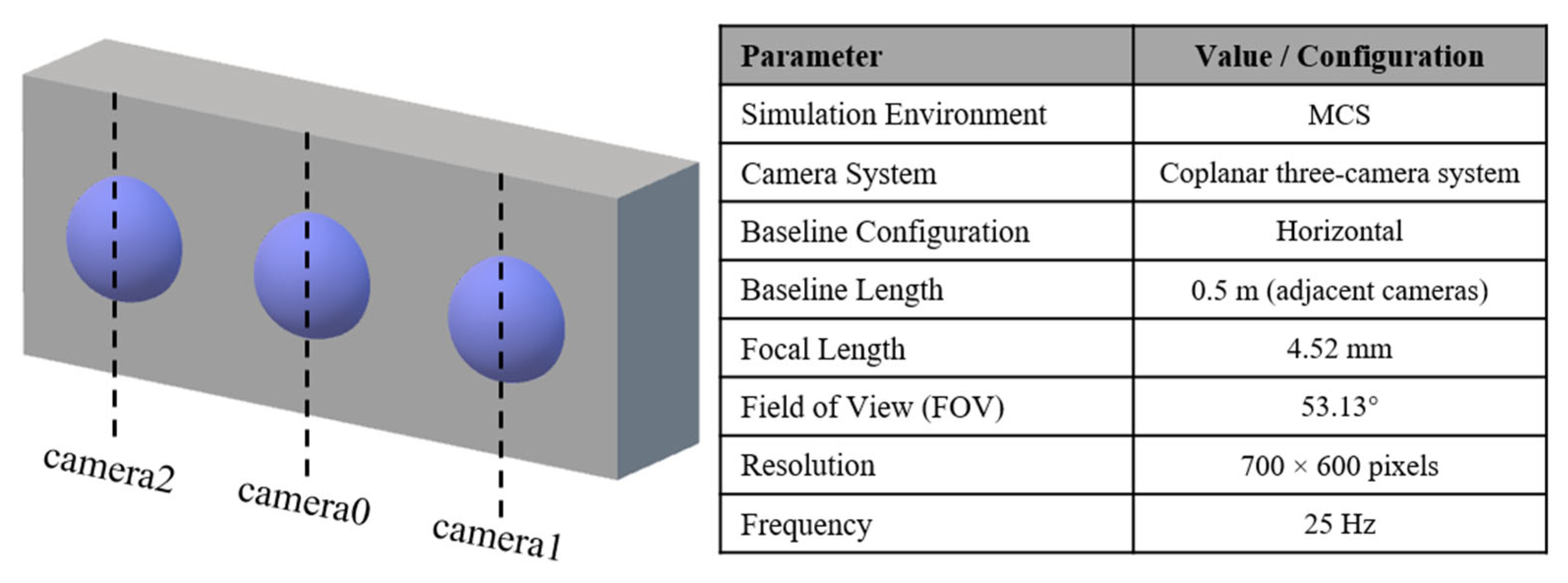
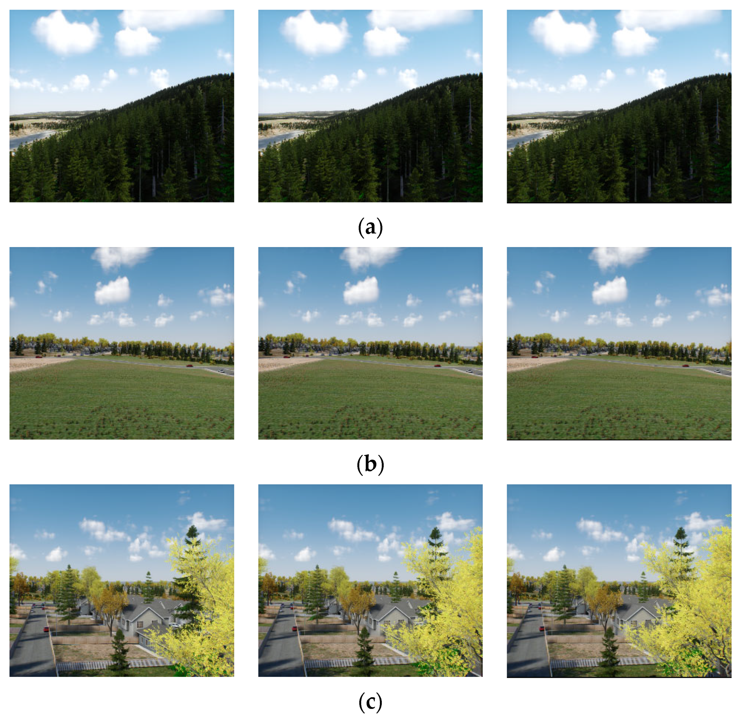
In the MCS simulation environment, a coplanar three-camera system was deployed as shown in Figure 3, based on a horizontal baseline configuration (adjacent cameras with a baseline length of 0.5 m, focal length of 4.52 mm, FOV of 53.13°, resolution of 700 × 600, and a frequency of 25 Hz). This system was rigidly mounted onto a simulated quadcopter UAV platform. The UAV follows a predefined U-shaped trajectory with a constant velocity of 10 m/s and an altitude varying between 30 m and 50 m (simulating realistic flight altitude changes). The simulation environment is deployed on a laptop equipped with an Intel Core i9-14900HX CPU, an NVIDIA GeForce RTX 4060 GPU, and 32 GB of RAM. Three challenging, typical wild field scenarios were selected (as shown in Figure 4):
  • Forest: dense vegetation coverage with large unstructured and visually similar regions;
  • Grass: open areas with sparse low vegetation and limited ground texture features;
  • Uptown: containing buildings, roads, and partial vegetation, with some structural features but also large homogeneous regions (e.g., walls and road surfaces).
The design of these scenarios aims to effectively evaluate the algorithm’s performance under large-scale weak textures, repetitive patterns, and unstructured environments. Data subsets collected from these three scenarios are named MCS_Forest1 (434.2 m), MCS_Grass1 (432.6 m), and MCS_Uptown1 (435.4 m). The weather is fixed to clear daytime with zero wind speed.

4.2. Comparative Experiments

A comparison is conducted with four representative open-source visual SLAM systems spanning different paradigms: indirect method-based (VINS-Fusion [24], ORB-SLAM3 [25]), direct method-based (DSOL [21]), and multi-camera method-based (MCVO [2]). On the KITTI dataset, all methods are evaluated under stereo configurations, while on MCSData, VINS-Fusion, ORB-SLAM3, and DSOL adopt stereo configurations, and both the proposed method and MCVO employ triple-camera setups. For evaluation, loop closure is disabled for all methods (as no loops are present in the simulated data), and the metric used is Absolute Trajectory Error (ATE) [26], which measures the Root Mean Square Error (RMSE) of the translational difference between the estimated trajectory and the ground-truth trajectory. For trajectories requiring alignment, the Umeyama algorithm is applied to align estimated trajectories with ground-truth data. As a standard metric in SLAM evaluation, ATE provides a global assessment of the overall trajectory accuracy, reflecting the accumulated drift and thus allowing for a comprehensive performance comparison between different methods.
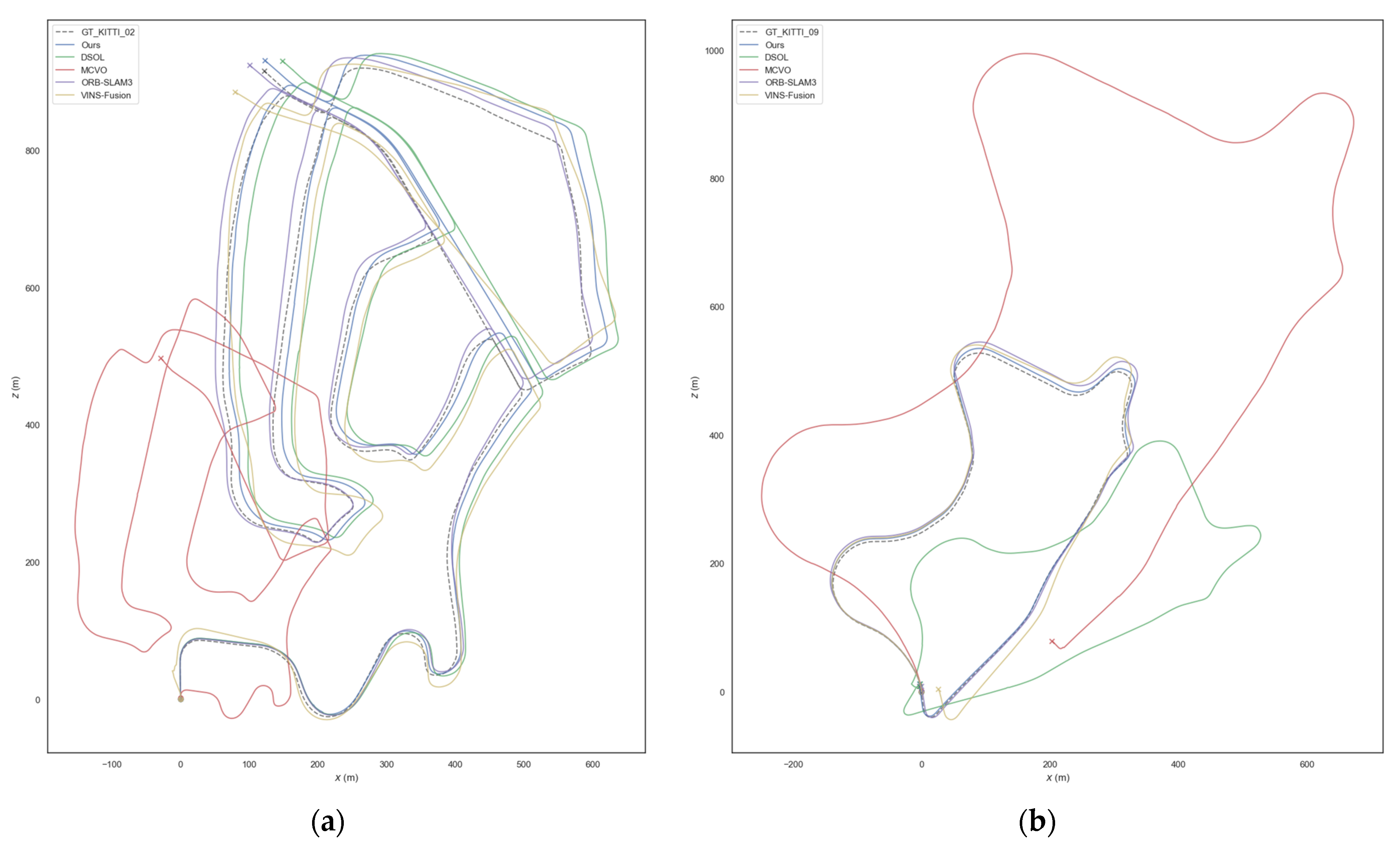
On the urban driving sequences of KITTI Odometry, a quantitative evaluation of all methods is conducted. As shown in Table 1, the proposed method achieves absolute trajectory translation errors of 0.51% and 0.73% on sequences 02 and 09. These results significantly outperform VINS-Fusion (0.76%, 1.09%) and DSOL (0.63%, 0.81%). Compared to the industry benchmark ORB-SLAM3 (0.32%, 0.69%), the proposed method maintains a low drift rate on the 5 km-long sequence 02 and achieves nearly equivalent accuracy on sequence 09 (a difference of only 0.04%). These results demonstrate that the proposed method attains localization accuracy comparable to state-of-the-art systems in feature-rich structured urban scenarios. Figure 5 shows the estimated trajectories of all methods on the KITTI dataset.
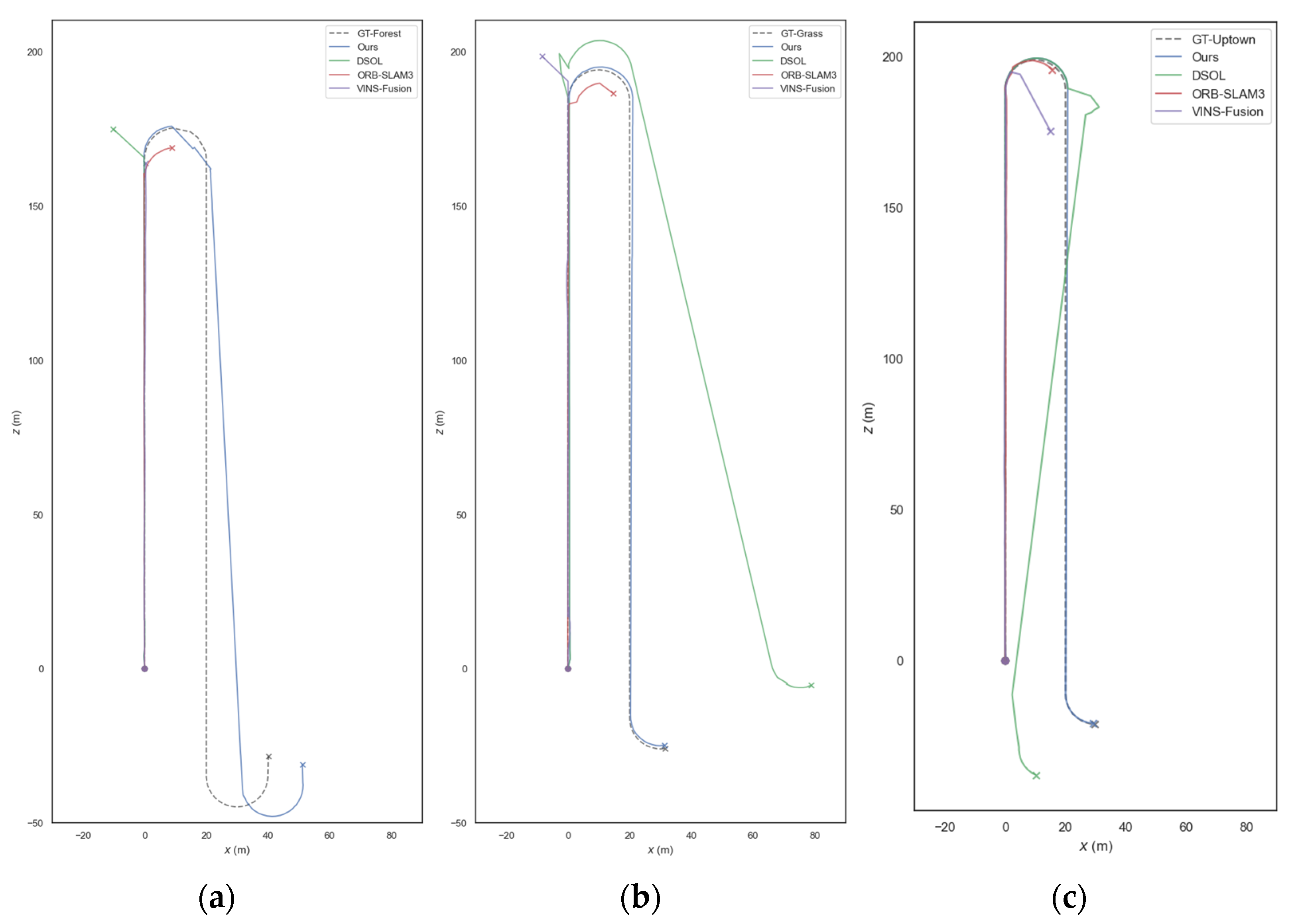
To further assess the robustness of the proposed method, it is evaluated on the more challenging MCSData dataset. Experimental results demonstrate that the proposed method exhibits superior robustness and localization accuracy on this dataset. As shown in Table 1, the proposed method achieves absolute trajectory translation errors of only 2.69%, 0.44%, and 0.34% on the MCS_Forest1, MCS_Grass1, and MCS_Uptown1 sequences, respectively, outperforming all compared methods.
In contrast, other approaches encounter severe difficulties in these unstructured and weakly textured scenarios. Feature-based methods such as VINS-Fusion and ORB-SLAM3 struggle to extract stable features, leading to severe drift with error rates generally exceeding 20%. It is noteworthy that MCVO failed to run successfully on all our MCSData sequences. We observed that although its SuperPoint feature extractor could detect keypoints, the system consistently failed to initialize. We speculate that this is related to its underlying methodology: MCVO aims to support arbitrary camera configurations by treating the multi-camera setup as multiple monocular cameras and achieving scale consistency through joint optimization. We believe that in challenging scenarios such as MCSData, the scale optimization algorithm of MCVO may fail to converge, resulting in initialization failure.
The primary advantage of our approach is rooted in its algorithmic design. First, our direct method does not rely on discrete feature points but solves for camera poses by minimizing pixel-level photometric errors. This mechanism enables the exploitation of subtle brightness gradients from lighting and surface materials in weakly textured regions, thereby ensuring robust tracking where feature-based approaches fail. Second, our pose estimation strategy provides high-precision initial pose estimates for initialization-sensitive direct methods, further enhancing robustness.
It is worth noting that DSOL, also based on direct methods, can complete tracking in the MCS_Grass1 (5.22%) and MCS_Uptown1 (1.82%) sequences. However, its simple constant velocity motion model fails to provide accurate initial poses during turns, resulting in significantly higher errors than the proposed method. This finding indirectly validates the effectiveness of our pose estimation strategy.
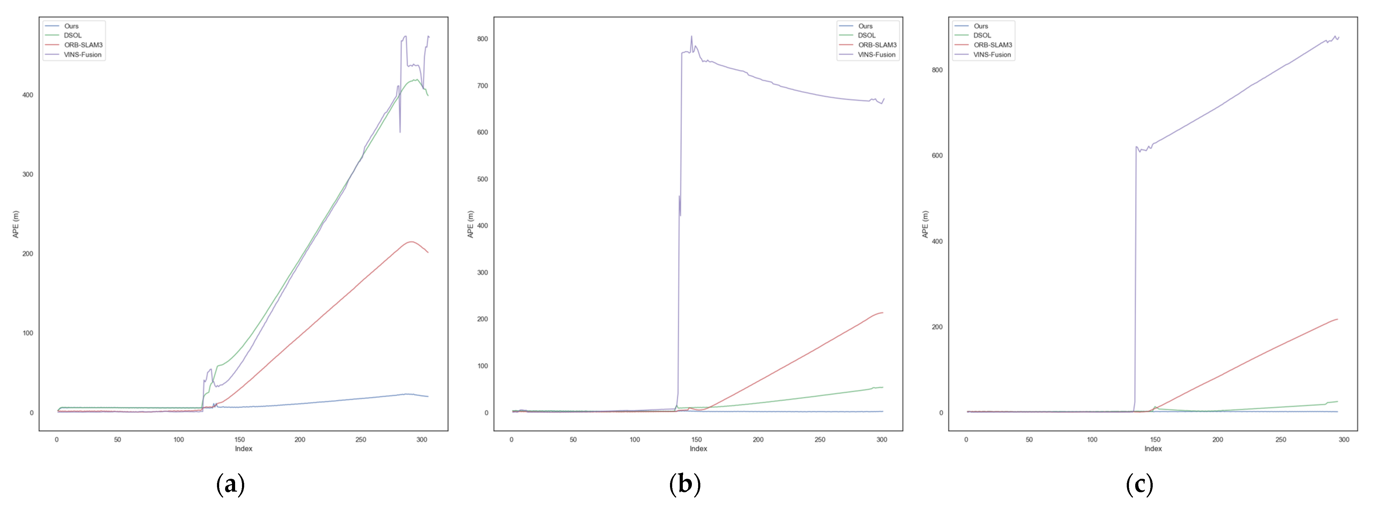
For a more comprehensive stability analysis, Table 2 reports the Absolute Trajectory Error prior to tracking failure and the corresponding tracking completion rates, while Figure 6 illustrates error evolution over frame indices. For example, ORB-SLAM3 achieves only 42.48% tracking completion before drifting in the MCS_Forest1 sequence. These quantitative results, together with the trajectory visualizations in Figure 7, consistently highlight the superiority of the proposed method in maintaining long-term stable tracking.

4.3. Experimental Analysis and Discussion

4.3.1. Ablation Analysis

To quantitatively analyze the independent contributions of each key component in our proposed framework, an ablation study was conducted on the MCSData dataset: (1) Ours (Full), representing the complete system; (2) Ours (w/o LoFTR Init), where the Efficient LoFTR-based front-end module is disabled and replaced with a conventional constant velocity model; and (3) Ours (w/o Multi-view BA), where the inter-camera geometric consistency constraint is removed from the back-end optimization, causing the back-end objective (Equation (7)) to degenerate into one containing only photometric error terms.
As shown in Table 3, the quantitative results validate the contributions of the two core components. When the Efficient LoFTR-based front-end is disabled and replaced by the constant velocity model, the system’s ATE deteriorates drastically compared with the complete system (Ours (Full)), rising from 11.69 m to 107.53 m (an increase of 820%) in the MCS_Forest1 scenario. This indicates that the conventional constant velocity model fails to provide sufficiently accurate initialization for photometric optimization, causing convergence to incorrect local minima, whereas the proposed front-end strategy is essential for robust system operation in challenging environments.
Similarly, when the inter-camera geometric consistency constraint is removed from the back-end, the ATE in the MCS_Forest1 scene increases from 11.69 m to 33.56 m (an increase of 187%), with noticeable degradation observed in other scenarios as well. This confirms that the proposed back-end design, through tightly coupled geometric constraints, effectively exploits the rigid multi-camera prior to suppress trajectory drift, which is crucial for improving final localization accuracy. In summary, the ablation experiments quantitatively validate that both the proposed front-end fusion strategy and the joint back-end optimization module are indispensable components of the system.

4.3.2. Runtime Performance

To evaluate the computational efficiency of our method, we recorded the total runtime of each system variant on the MCS_Grass1 sequence (containing 301 frames). All experiments were conducted on a hardware platform equipped with an Intel Xeon 8352V CPU and an NVIDIA GeForce RTX 4090D GPU.
As shown in Table 4, our complete system (93.65 s) exhibits a longer total runtime compared to the lightweight ORB-SLAM3 (31.14 s). However, the primary contribution of our system lies not in computational speed but in robustness and high accuracy under challenging weakly textured environments, where traditional methods such as ORB-SLAM3 fail to maintain tracking (as demonstrated in Section 4.2).
To further investigate the computational bottleneck and justify the runtime overhead, we provide a detailed time breakdown of our complete system (“Ours (Full)”) in Table 5.
The breakdown in Table 5 identifies the LoFTR Init module as the primary computational cost, accounting for approximately 55.5% of the total runtime. The trigger count (300 triggers for 301 frames) indicates that the deep learning matcher is invoked on a nearly frame-by-frame basis during the tracking stage.
Employing this high-cost module on non-key frames is a deliberate design choice specifically tailored for unstructured environments. In scenes with sparse or repetitive textures (e.g., grasslands), the Constant Velocity Model used by traditional direct methods often fails to provide accurate inter-frame pose predictions, causing the photometric alignment to fall into incorrect local minima. By utilizing LoFTR for dense association in every frame, we ensure a robust initialization for the direct method. Therefore, the additional computational overhead represents a necessary trade-off to achieve reliable performance in environments where standard algorithms collapse.
In terms of system resource consumption, as shown in Table 4, the peak RAM usage is approximately 2.5 GB. While higher than ORB-SLAM3 (0.5 GB), it remains well within the capacity of typical robotic computing platforms (e.g., 8 GB + RAM). The average GPU utilization on our test platform (RTX 4090D) was recorded at approximately 60%. While this indicates high computational demand suitable for high-end workstations, the memory footprint (Table 4) is compatible with embedded platforms, supporting our future goal of model compression for UAV deployment.

4.3.3. Analysis of Generalization Ability and Sim-to-Real Gap

The proposed method focuses on solving the challenge of localization stability for Visual SLAM in environments characterized by weak textures, repetitive patterns, and unstructured geometry. The superior robustness of the system is rigorously validated using the MCSData dataset, which was constructed based on the self-developed and verified MCS-Sim system [23]. The underlying infrastructure of the simulation system is built upon the industrial-grade 3D engine UNIGINE, known for its photo-realistic rendering capabilities and accurate physics simulation. This allows for high-fidelity simulation of complex illumination changes, shadow occlusion, and the physical reflection properties of different materials. As demonstrated in related publications, MCS-Sim has been proven effective in evaluating various 3D vision algorithms, including optical flow estimation, depth prediction, and SLAM.
Our results provide strong Indirect Validation of the method’s generalization potential. In comparative experiments, established systems such as VINS-Fusion and ORB-SLAM3 consistently exhibited severe drift or tracking failure in the MCSData weak-texture sequences. This “failure consistency” indicates that our simulation environment successfully captures the core difficulties of the real world that cause Visual SLAM failure (i.e., the challenges of weak textures, repetitive patterns, and unstructured scenes), demonstrating that the robustness achieved in this controlled environment has the potential to transfer to real-world applications. It is noted that, while this high-fidelity framework accurately models photometric and geometric complexities, the current dataset does not explicitly incorporate all real-world dynamic factors such as sensor noise, significant motion blur, or complex dynamic foliage. As stated in the Conclusion, deployment and testing on physical UAV platforms remain the primary goal for future work.

5. Conclusions

In this paper, a multi-camera visual SLAM framework based on direct methods is proposed, which integrates a detector-free Efficient LoFTR matcher in the front-end to provide robust initial pose estimates and incorporates cross-camera geometric constraints in the back-end for joint optimization, effectively addressing the stability issues of traditional methods in complex unstructured environments such as weakly or repetitively textured scenes, while enhancing positioning accuracy in such scenarios. Experiments demonstrate that in weakly textured simulation scenarios (MCSData), the localization accuracy and robustness significantly outperform mainstream methods such as VINS-Fusion and ORB-SLAM3 (with an average drift error reduction exceeding 20% compared to these methods, or failure occurring after approximately 40% of the trajectory length).
Nevertheless, we acknowledge that the present validation does not fully capture the full complexity of real-world conditions. Factors such as dynamic vegetation, severe illumination variations, occlusions, motion blur, and sensor noise remain common challenges for current visual SLAM systems.
Given these limitations and with an outlook toward future research, our ongoing work will focus on the following aspects:
First and foremost, the proposed system will be deployed on real mobile platforms for rigorous evaluation. This includes two closely related steps: (1) at the algorithmic level, inertial measurement units (IMU) will be tightly integrated to build a more robust visual–inertial odometry system capable of handling aggressive motions and rapid rotations; (2) at the experimental level, we will systematically test and validate the system using UAVs or other mobile platforms equipped with multi-camera–IMU systems in complex, dynamic real-world scenarios with significant illumination changes.
Secondly, we plan to explore additional directions for enhancing system performance and scalability: (3) We will investigate the impact of varying the number and configuration of cameras on the trade-offs among accuracy, robustness, and computational efficiency. We expect that increasing the number of cameras can improve localization accuracy and robustness by expanding the field of view and strengthening geometric constraints in the back-end, but at the cost of increased computational demand. Regarding camera layout, provided accurate extrinsic calibration is maintained, its influence on algorithmic behavior may be minor; however, different configurations (e.g., baseline lengths) could still affect task-specific performance such as depth estimation, which merits further exploration. (4) We will incorporate semantic information to enhance robustness in dynamic environments and enable richer map representations. (5) We will study online adaptive parameter adjustment strategies to improve adaptability across different environments. (6) We will investigate techniques to enhance robustness to severe illumination variations, such as introducing photometric calibration mechanisms. (7) We will optimize computational efficiency by addressing the major bottleneck identified in Section 4.3.2—namely, the Transformer-based Efficient LoFTR matcher in the front-end. Future efforts will explore model compression techniques, including model distillation and weight quantization tailored to this network. In addition, we plan to evaluate more lightweight detector-free matching architectures to substantially reduce front-end computational latency while preserving robustness, thereby advancing the system toward real-time capability.

Author Contributions

Conceptualization, Y.P. and G.W.; methodology, Y.P.; software, Y.P.; validation, Y.Z., G.W. and J.H.; formal analysis, G.W.; investigation, Y.P.; resources, H.F.; data curation, Y.P.; writing—original draft preparation, Y.P.; writing—review and editing, G.W.; visualization, Q.Q.; supervision, Y.J.; project administration, H.F.; funding acquisition, H.F. All authors have read and agreed to the published version of the manuscript.

Funding

This research was funded by the National Natural Science Foundation of China, grant numbers 62303478 and 62401588, along with the Science Foundation of National University of Defense Technology, grant number 202401–YJRC–XX-010.

Data Availability Statement

The data presented in this study are available upon request from the corresponding author.

Conflicts of Interest

The authors declare no conflicts of interest.

Abbreviations

The following abbreviations are used in this manuscript:
SLAMSimultaneous Localization and Mapping
vSLAMVisual Simultaneous Localization and Mapping
DSODirect Sparse Odometry
BABundle Adjustment
ATEAbsolute Trajectory Error
SVDSingular Value Decomposition
RANSACRandom Sample Consensus

References

  1. Pritchard, T.; Ijaz, S.; Clark, R.; Kocer, B. ForestVO: Enhancing Visual Odometry in Forest Environments through ForestGlue. IEEE Robot. Autom. Lett. 2025, 10, 5233–5240. [Google Scholar] [CrossRef]
  2. Yu, H.; Wang, J.; He, Y.; Yang, W.; Xia, G.S. MCVO: A Generic Visual Odometry for Arbitrarily Arranged Multi-Cameras. arXiv 2024, arXiv:2412.03146. [Google Scholar] [CrossRef]
  3. Tourani, A.; Bavle, H.; Sanchez-Lopez, J.; Voos, H. Visual SLAM: What Are the Current Trends and What to Expect? Sensors 2022, 22, 9297. [Google Scholar] [CrossRef] [PubMed]
  4. Davison, A.; Cid, Y.; Kita, N. Real-Time 3D SLAM with Wide-Angle Vision. IFAC Proc. Vol. 2004, 37, 868–873. [Google Scholar] [CrossRef]
  5. Ragab, M. Multiple Camera Pose Estimation. Ph.D. Thesis, The Chinese University of Hong Kong, Hong Kong, 2008. [Google Scholar]
  6. Harmat, A.; Trentini, M.; Sharf, I. Multi-Camera Tracking and Mapping for Unmanned Aerial Vehicles in Un-Structured Environments. J. Intell. Robot. Syst. 2015, 78, 291–317. [Google Scholar] [CrossRef]
  7. Yang, A.; Cui, C.; Barsan, I.; Urtasun, R.; Wang, S. Asynchronous Multi-View SLAM. In Proceedings of the 2021 IEEE International Conference on Robotics and Automation (ICRA), Xi’an, China, 30 May–5 June 2021. [Google Scholar]
  8. Zhang, L.; Wisth, D.; Camurri, M.; Fallon, M. Balancing the Budget: Feature Selection and Tracking for Multi-Camera Visual-Inertial Odometry. IEEE Robot. Autom. Lett. 2021, 7, 1182–1189. [Google Scholar] [CrossRef]
  9. Song, H.; Liu, C.; Dai, H. BundledSLAM: An Accurate Visual SLAM System Using Multiple Cameras. In Proceedings of the 2024 IEEE 7th Advanced Information Technology, Electronic and Automation Control Conference (IAEAC), Chongqing, China, 15–17 March 2024. [Google Scholar]
  10. Mur-Artal, R.; Tardós, J. ORB-SLAM2: An Open-Source SLAM System for Monocular, Stereo, and RGB-D Cameras. IEEE Trans. Robot. 2017, 33, 1255–1262. [Google Scholar] [CrossRef]
  11. Yang, Y.; Pan, M.; Tang, D.; Wang, T.; Yue, Y.; Liu, T.; Fu, M. MCOV-SLAM: A Multi-Camera Omnidirectional Visual SLAM System. IEEE/ASME Trans. Mechatron. 2024, 29, 3556–3567. [Google Scholar] [CrossRef]
  12. Pan, M.; Li, J.; Zhang, Y.; Yang, Y.; Yue, Y. MCOO-SLAM: A Multi-Camera Omnidirectional Object SLAM System. arXiv 2025, arXiv:2506.15402. [Google Scholar] [CrossRef]
  13. Mao, H.; Luo, J. PLY-SLAM: Semantic Visual SLAM Integrating Point–Line Features with YOLOv8-seg in Dynamic Scenes. Sensors 2025, 25, 3597. [Google Scholar] [CrossRef] [PubMed]
  14. Engel, J.; Koltun, V.; Cremers, D. Direct Sparse Odometry. IEEE Trans. Pattern Anal. Mach. Intell. 2017, 40, 611–625. [Google Scholar] [CrossRef] [PubMed]
  15. Lu, S.; Zhi, Y.; Zhang, S.; He, R.; Bao, Z. Semi-Direct Monocular SLAM with Three Levels of Parallel Optimizations. IEEE Access 2021, 9, 86801–86810. [Google Scholar] [CrossRef]
  16. Liu, W.; Zhou, W.; Liu, J.; Hu, P.; Cheng, J.; Han, J.; Lin, W. Modality-Aware Feature Matching: A Comprehensive Review of Single- and Cross-Modality Techniques. arXiv 2025, arXiv:2507.22791. [Google Scholar]
  17. Sun, J.; Shen, Z.; Wang, Y.; Bao, H.; Zhou, X. LoFTR: Detector-Free Local Feature Matching with Transformers. In Proceedings of the IEEE/CVF Conference on Computer Vision and Pattern Recognition, Nashville, TN, USA, 20–25 June 2021. [Google Scholar]
  18. Wang, Y.; He, X.; Peng, S.; Tan, D.; Zhou, X. Efficient LoFTR: Semi-Dense Local Feature Matching with Sparse-Like Speed. In Proceedings of the IEEE/CVF Conference on Computer Vision and Pattern Recognition, Seattle, WA, USA, 16–22 June 2024. [Google Scholar]
  19. Wang, Q.; Zhang, J.; Yang, K.; Peng, K.; Stiefelhagen, R. MatchFormer: Interleaving Attention in Transformers for Feature Matching. In Proceedings of the Asian Conference on Computer Vision, Macao, China, 4–8 December 2022. [Google Scholar]
  20. He, X.; Sun, J.; Wang, Y.; Peng, S.; Huang, Q.; Bao, H.; Zhou, X. Detector-Free Structure from Motion. In Proceedings of the IEEE/CVF Conference on Computer Vision and Pattern Recognition, Seattle, WA, USA, 16–22 June 2024. [Google Scholar]
  21. Qu, C.; Shivakumar, S.; Miller, I.; Taylor, C. DSOL: A Fast Direct Sparse Odometry Scheme. In Proceedings of the 2022 IEEE/RSJ International Conference on Intelligent Robots and Systems (IROS), Kyoto, Japan, 23–27 October 2022. [Google Scholar]
  22. Geiger, A.; Lenz, P.; Urtasun, R. Are We Ready for Autonomous Driving? The KITTI Vision Benchmark Suite. In Proceedings of the 2012 IEEE Conference on Computer Vision and Pattern Recognition (CVPR), Providence, RI, USA, 16–21 June 2012. [Google Scholar]
  23. Qi, Q.; Wang, G.; Pan, Y.; Fan, H.; Li, B. MCS-Sim: A Photo-Realistic Simulator for Multi-Camera UAV Visual Perception Research. Drones 2025, 9, 656. [Google Scholar] [CrossRef]
  24. Qin, T.; Cao, S.; Pan, J.; Shen, S. A General Optimization-Based Framework for Global Pose Estimation with Multiple Sensors. arXiv 2019, arXiv:1901.03642. [Google Scholar] [CrossRef]
  25. Campos, C.; Elvira, R.; Rodríguez, J.J.G.; Montiel, J.M.; Tardós, J.D. ORB-SLAM3: An Accurate Open-Source Library for Visual, Visual–Inertial, and Multi-Map SLAM. IEEE Trans. Robot. 2021, 37, 1874–1890. [Google Scholar] [CrossRef]
  26. Jürgen, S.; Nikolas, E.; Felix, E.; Wolfram, B.; Daniel, C. A benchmark for the evaluation of RGB-D SLAM systems. In Proceedings of the 2012 IEEE/RSJ International Conference on Intelligent Robots and Systems (IROS), Vilamoura, Portugal, 7–12 October 2012. [Google Scholar]
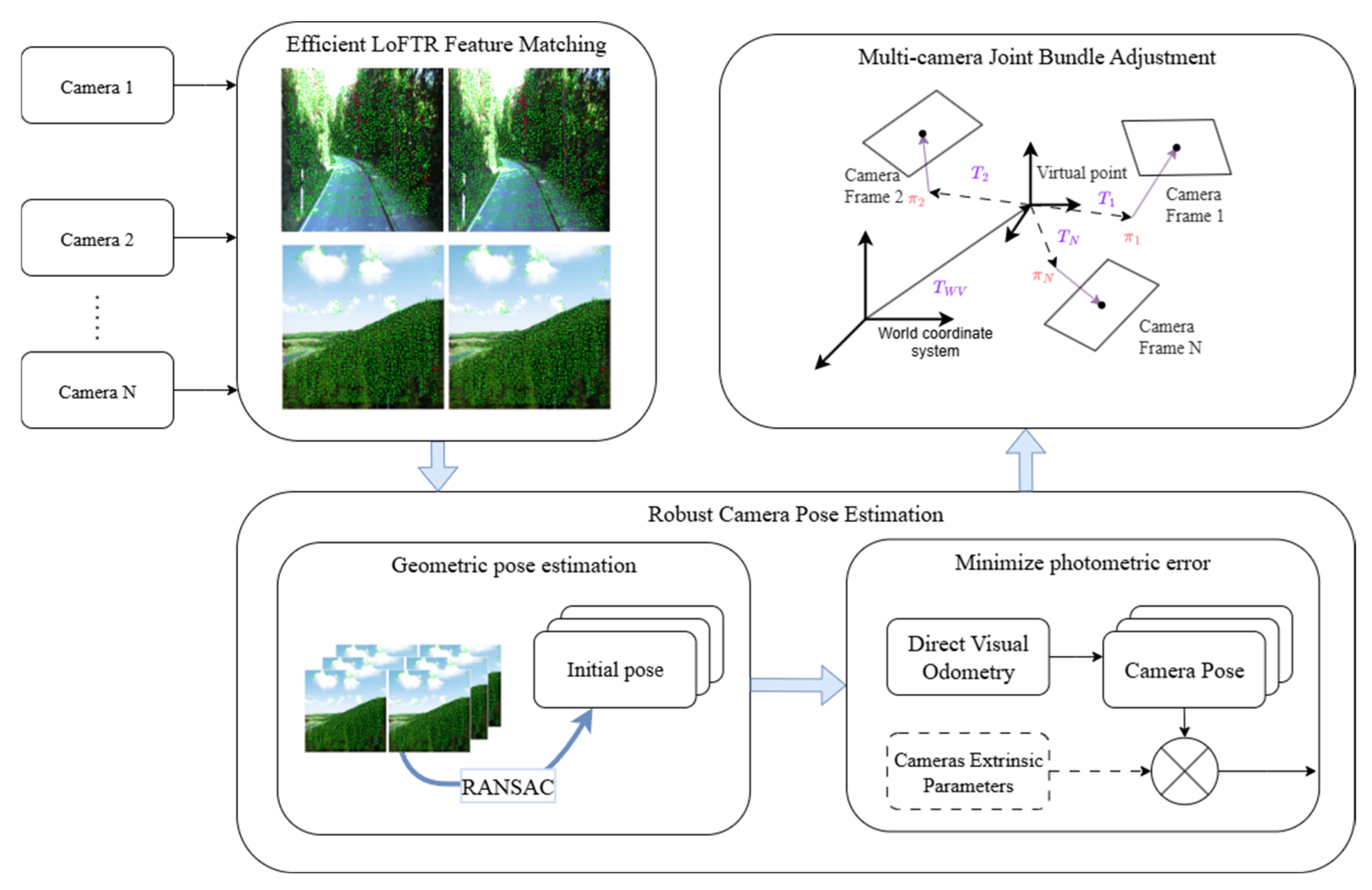
Figure 1. The pipeline of the proposed method. The system processes synchronized multi-camera image sequences. In the feature matching module, green points represent valid inliers, while red points represent outliers. The ellipsis (…) denotes the set of intermediate cameras between Camera 2 and Camera N. The crossed circle symbol indicates the combination of the initial pose with extrinsic parameters. In the rightmost diagram, solid arrows represent coordinate axes, while dashed arrows denote coordinate transformations ( T ) and projection functions ( π ).
Electronics 14 04556 g001
Figure 2. System Control Flow Diagram.
Electronics 14 04556 g002
Figure 3. Schematic illustration of three-camera system.
Electronics 14 04556 g003
Figure 4. MCSData Dataset Schematic Diagram, each row’s three images originate from an array composed of three cameras: (a) MCS_Forest1; (b) MCS_Grass1; (c) MCS_Uptown1.
Electronics 14 04556 g004
Figure 5. Trajectories of Each Algorithm on the KITTI Dataset: (a) KITTI_02; (b) KITTI_09. The “×” symbols denote the end points of the trajectories, indicating where the tracking terminated.
Electronics 14 04556 g005
Figure 6. Results of error variation with image index: (a) MCS_Forest1; (b) MCS_Grass1; (c) MCS_Uptown1.
Electronics 14 04556 g006
Figure 7. Trajectories of Each Algorithm on the MCSData: (a) MCS_Forest1; (b) MCS_Grass1; (c) MCS_Uptown1.
Electronics 14 04556 g007
Table 1. Absolute Trajectory Error (ATE). Failed indicates that the algorithm failed to run on this sequence.
KITTI_02
(5067.2 m)
KITTI_09
(1705.1 m)
MCS_Forest1
(434.2 m)
MCS_Grass1
(432.6 m)
MCS_Uptown1
(435.4 m)
VINS-Fusion0.76%1.09%48.03%121.09%126.83%
ORB-SLAM30.32%0.69%23.73%20.22%21.17%
DSOL0.63%0.81% a46.74%5.22%1.82%
MCVO1.88% a,s2.21% a,sFailedFailedFailed
Ours0.51%0.73%2.69%0.44%0.34%
a Alignment with Umeyama’s method (no scale). s Correct scale with Umeyama’s method.
Table 2. Absolute trajectory error prior to tracking failure and corresponding tracking completion rate.
MCS_Forest1
(434.2 m)
MCS_Grass1
(432.6 m)
MCS_Uptown1
(435.4 m)
DSOL5.70 m
(39.54%)
2.66 m
(44.70%)
1.51 m
(50.34%)
ORB-SLAM32.18 m
(42.48%)
1.60 m
(48.01%)
0.89 m
(48.65%)
VINS-Fusion0.49 m
(39.22%)
3.54 m
(44.37%)
2.17 m
(45.27%)
Table 3. Ablation experiment results; the errors in the table represent the Absolute Trajectory Error (ATE).
Ours
(w/o LoFTR Init)
Ours
(w/o Multi-View BA)
Ours
(Full)
MCS_Forest1107.53 m33.56 m11.69 m
MCS_Grass151.37 m2.24 m1.90 m
MCS_Uptown126.73 m1.73 m1.49 m
Table 4. Runtime Performance on the MCS_Grass1 Sequence.
Ours
(w/o LoFTR Init)
Ours
(w/o Multi-view BA)
Ours
(Full)
ORB-SLAM3
Time37.13 s52.34 s93.65 s31.14 s
RAM Usage1.2 GB2.5 GB2.5 GB0.5 GB
Table 5. Detailed Module Runtime Breakdown for “Ours (Full)” on MCS_Grass1 (301 frames).
ModuleTrigger CountTotal TimeAvg. Time per Trigger
LoFTR Init30051.97 s173.2 ms
Tracking3000.76 s2.5 ms
Multi-view BA6222.42 s361.6 ms
Other Overheads-18.50 s-
Ours (Full)-93.65 s-
Disclaimer/Publisher’s Note: The statements, opinions and data contained in all publications are solely those of the individual author(s) and contributor(s) and not of MDPI and/or the editor(s). MDPI and/or the editor(s) disclaim responsibility for any injury to people or property resulting from any ideas, methods, instructions or products referred to in the content.