Article

Low-Cost Transmitarray Design with High Gain Bandwidth and Suppressed SLL

1
Department of Electrical and Electronics Engineering, Bilecik Şeyh Edebali University, 11230 Bilecik, Türkiye
2
Department of Electronics and Communication Engineering, Kocaeli University, 41001 Kocaeli, Türkiye
*
Author to whom correspondence should be addressed.
Electronics 2025, 14(20), 4044; https://doi.org/10.3390/electronics14204044
Submission received: 10 September 2025 / Revised: 7 October 2025 / Accepted: 13 October 2025 / Published: 15 October 2025
(This article belongs to the Section Microwave and Wireless Communications)

Abstract

This study presents a transmitarray antenna design operating at a center frequency of 9 GHz, addressing the need for high-gain and broad bandwidth antennas in modern data communication. The proposed design is structured as a quad-layer configuration using FR-4 dielectric substrates. The transmitarray’s phase profile is tailored to deliver a wideband flat response with low Side Lobe Level (SLL) and stable aperture efficiency across the operating band. It achieves a 1-dB gain bandwidth of 12.12% (from 8.56 GHz to 9.67 GHz) and a 3-dB gain bandwidth of 49.43% (from 8.45 GHz to 13.46 GHz) with an aperture efficiency of 21.3%. A prototype of the proposed design with 11 × 11 elements was fabricated and measured, and its measurement results closely aligned with simulation results, validating its performance. The proposed simple design realizes reduced complexity and fabrication costs while expanding operational gain bandwidth, thereby demonstrating substantial promise for next-generation X-band communication systems.

1. Introduction

Transmitarray antennas, with their low spatial profile, cost-efficient fabrication, conformal capabilities, and ability to generate high-gain beams [1], are ideally suited for various important applications, such as 5G communication [2,3], millimeter-wave applications [4], V-band applications [5], and tracking radar systems [6]. By combining the principles of lens and microstrip array technologies, transmitarray antennas offer several notable advantages, including high efficiency, high gain, compact size, and lightweight construction [7]. Transmitarray antennas demonstrate superiority over reflectarrays by achieving high radiation efficiency without the issue of feed blockage [8,9]. However, transmitarray antennas are limited by narrow bandwidth and lower efficiency, primarily due to reduced transmission magnitude and the inherent narrowband characteristics of their elements [10,11]. Consequently, the development of transmitarray antennas with enhanced efficiency and broader bandwidth is of critical importance to address these limitations and meet the demands of modern applications.
In transmitarray design, the primary focus lies in developing the transmitarray unit cells. These cells must achieve a broad transmission phase range, ideally spanning 360° or more, alongside a high transmission magnitude.
Multiple techniques are available to facilitate the design of these unit cells. One of them is Huygens’ metasurface structures. Huygens’ metasurface has the advantages of simple fabrication with only two layers on a thin substrate [12]. Reference [13] presents a conformal transmitarray with high efficiency, employing an ultrathin dual-layer Huygens’ element. They utilized a pair of metallic layers on a single substrate of thickness λ0/60, and the antenna achieved a peak efficiency of 47%. As reported in [14], a novel transmitarray antenna based on Huygens’ metasurfaces is presented. Using wire and loop unit cells on a low-profile 0.2λ0 aperture, it achieves a high aperture efficiency of 65% with a bandwidth of 14% and a Side Lobe Level (SLL) of −19 dB. In [15], a wideband E-band conformal transmitarray using dual-layer Huygens’ elements with overlapped metallic strips is developed, achieving efficient phase control from 71 to 87 GHz. The prototype at 78 GHz reaches a 26.6 dB peak gain, 37.2% aperture efficiency, and 20.4% 3-dB gain bandwidth.
Another technique for the design of transmitarray unit cell is receiver–transmitter radiating elements. In [16], a double-folded transmitarray antenna exhibiting circular polarization is proposed, realized by combining receiver–transmitter metasurfaces with a polarization-rotating layer. The design reduces the antenna profile to 1/4 of the focal length and achieves a peak gain of 21.8 dB at 9.8 GHz, with 40% aperture efficiency and a 6% bandwidth for a 1-dB gain. Ref. [17] introduces a reconfigurable Ku-band transmitarray with independent dual linear polarization control using a 1-bit receiver–transmitter element. Phase shift is achieved via two pin diodes. The prototype achieves an 18.3 dB gain at 12.2 GHz with 22.6% aperture efficiency and ±50° beam-scanning, showing a maximum scan loss of 2.9 and 3.5 dB in principal planes.
FSS structures and patch antennas are widely utilized as transmitarray elements due to their simplicity. However, this simplicity also significantly restricts the bandwidth achievable by the transmitarray antenna. Although multilayer FSS configurations [18,19,20,21,22,23] have been implemented to enhance bandwidth, their fabrication and assembly processes become highly complex, especially at higher operating frequencies.
Beyond efficiency and reconfigurability, Side Lobe Level (SLL) is a decisive metric for array performance. Achieving low SLL requires coordinated amplitude–phase control across the aperture [24]. Evidence across diverse array platforms shows this joint shaping can push SLL well below −20 dB: a 5.8 GHz CP ETC array optimized via weighted constrained method of the maximum power transmission efficiency (WCMMPTE) reports −30 dB SLL with preserved gain/beamwidth [25]; an extended method of maximum power transmission efficiency (EMMPTE)-based weighted design with particle swarm optimization (PSO) yields multi-beam synthesis with explicit SLL suppression and reduced search complexity [26]; and a compact cosecant-squared array meets coverage targets while maintaining SLL < −20 dB [27]. These results motivate SLL-aware synthesis as a first-class design objective in our work.
In the study [28], the folded configuration of a phase-gradient reflective surface, the space sandwiched by the transmitarray surface, is proposed. A 1-bit phase resolution, capable of supporting only two discrete phase states (0° and 180°), is employed. In the design, the feed pin operates in concert with the surrounding shorting vias to channel energy from the input port to the excitation region. The measured results demonstrate a 3-dB gain bandwidth of 26% for x-polarization and a peak aperture efficiency of 21%.
In this work, a simple unit cell structure, resembling the one presented in [28], is designed to achieve a full 360° phase range. Unlike the previous design, the proposed multilayer unit cell configuration does not employ additional components such as feeding pins or shorting vias. Using this simplified element, the resulting antenna array achieves 1-dB and 3-dB gain bandwidths of 12.12% and 49.43%, respectively, along with an aperture efficiency of 21.3%. Also, the proposed transmitarray has an SLL of −24.89 dB in the E-planes at 9 GHz. By adopting a multilayer FSS architecture on an FR-4 substrate, we obtained a wide gain bandwidth while keeping the design via-free and low-cost. Additionally, the unit cell structures in the multilayer FSS were chosen to be simple, which streamlined the manufacturing process. Consequently, we achieved a total thickness of 0.37λ0, avoiding a bulky structure.

2. Unit Cell Design

Figure 1 illustrates the presented unit cell design, which consists of four dielectric layers and four metallic layers, including a plus-shaped patch at the center and squares located in the four segments of the plus shape. The horizontal and vertical lengths of the plus-shaped patch differ from each other, and the side lengths of the squares are related to the lengths of the plus-shaped patch. By changing the lengths, a phase range of 360° was achieved, thereby having a total transmission phase coverage of 360° to create a transmitarray with complete effective performance [29].
All results were obtained in CST Microwave Studio (Frequency-Domain Solver). For unit cell characterization, unit cell periodic boundaries were applied on ± x , ± y , while Floquet ports were assigned on ± z (with Open (add space) termination) to realize a top-down, normally incident plane wave.
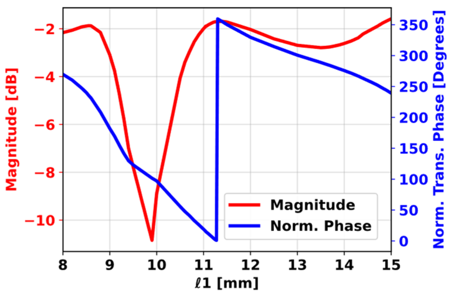
The optimized parameters were obtained as follows: while the length l 1 varies between 8   m m 0.24 λ 0 and 15   m m   ( 0.45 λ 0 ) the parameters z = 1.6   m m 0.048 λ 0 , p   =   17   m m 0.51 λ 0 , l = l 1 × 0.6 , l 2 = l 1 × 0.4 , and h = 2   m m   ( 0.06 λ 0 ) were used, where λ 0 denotes the wavelength in free space (at 9 GHz). Figure 2 illustrates the normalized transmission phase at the 9 GHz frequency. The results (Figure 2) confirm that the unit cell achieves a complete 360-degree phase coverage.
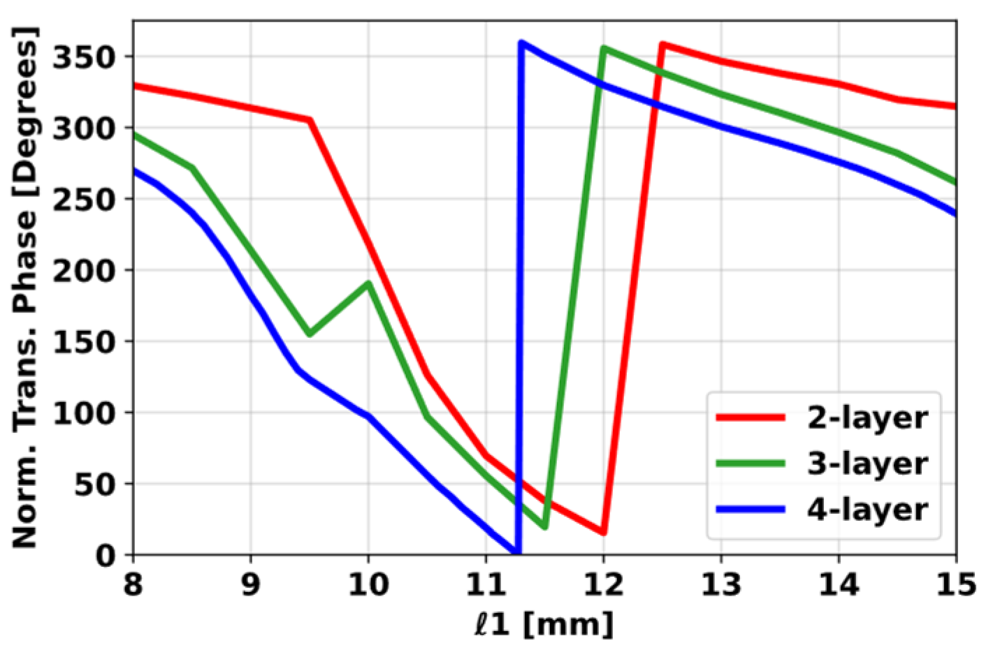
To substantiate the choice of the four-layer unit cell, Figure 3 compares the phase tuning at 9 GHz for two-, three-, and four-layer stacks. Only the four-layer configuration achieves full 0–360° coverage without phase gaps and maintains a quasi-monotonic slope across the l 1 sweep, which reduces quantization error in the aperture phase map. In contrast, the two-layer variant does not provide sufficient phase depth, and the three-layer version shows a phase singularity (jump) complicating phase assignment. Consequently, the four-layer via-free FR-4 stack was selected as it meets the phase-range requirement while keeping the fabrication flow compatible with standard PCB processes.

3. Design and Measurement of the Proposed Transmitarray with High Gain Bandwidth and Suppressed SLL

Following the completion of the design process of the presented transmitarray unit cell structure, the transmitarray antenna can be designed based on the phase compensation theory. During the synthesis of the transmitarray, the transmission phase for each element is typically derived to offset the phase lag introduced by the differing path lengths between the feed and every individual cell in the lattice. This phase distribution is necessary to focus the beam in a specific direction. Producing a high-gain beam requires the transmitarray to convert the spherical wave emerging from the feed into a planar wavefront; hence, the phase imparted by each unit cell is selected compensating for the spatial phase difference between the feed and the unit in question.
ψ i j = k R i j r i j · r ^ 0 + ψ 0
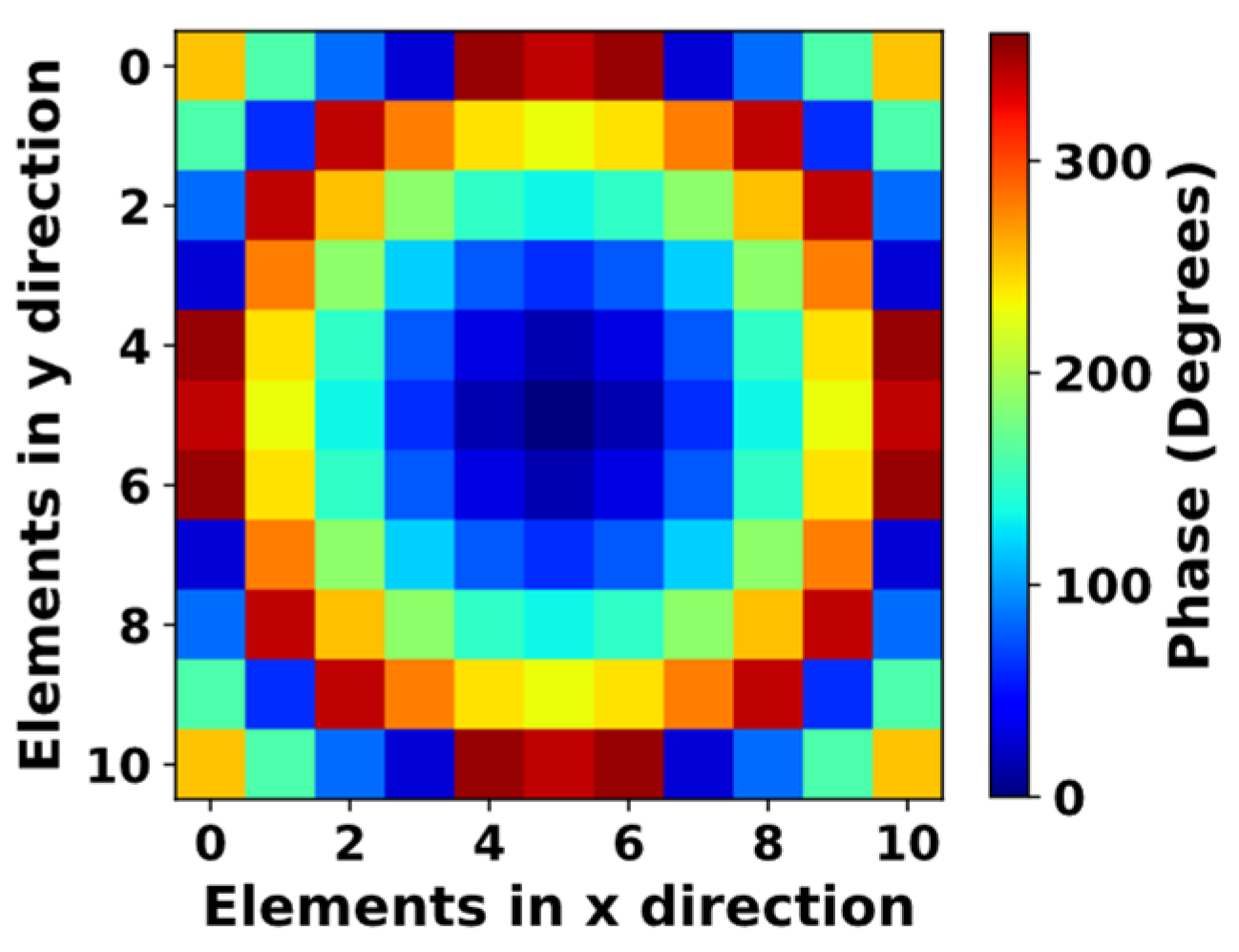
In Equation (1), ψ i j represents the transmission phase in degrees required for the ij-th unit cell, k denotes the propagation constant in free space, R i j is the distance in meters from the feed antenna to the center of the ij-th element, r i j is the position vector for the ij-th element, r ^ 0 is the unit vector of the main beam, and ψ 0 represents the phase offset in degrees. Using this equation, the phase distributions for the unit cell are calculated. The phase distribution diagram of the transmitarray illustrated in Figure 4, which is structured using this calculation.
Aperture efficiency is a crucial performance metric for transmitarray antennas. To enhance the aperture efficiency and minimize spillover loss, it is essential to select an optimal focal length to aperture dimension ratio (often denoted f D ) during the optimization stage of the design [30]. Each unit cell’s phase is then precisely adjusted to ensure a consistent phase profile over the radiating aperture, thereby maximizing gain.
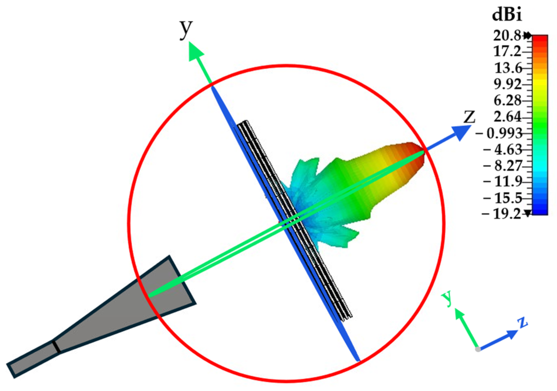
Figure 5 illustrates the simulation model of the transmitarray antenna, consisting of 11 × 11 unit cells and fed by a horn antenna, as analyzed in CST Microwave Studio. Figure 6 depicts the comprehensive layout of the proposed broadband transmitarray. The array consists of a multilayer structure, featuring a periodic lattice of unit cells arranged in four layers. The array has a square outline comprising 121 unit cells, giving it a total aperture of 187 mm. Its thickness amounts to 0.372 λ 0 , where λ 0 denotes the wavelength in free space wavelength at 9 GHz, while the horn feed is set to 99 mm with respect to the array’s center, resulting in an f D ratio of 0.53. A pyramidal horn antenna with a taper length of 120 mm and an aperture size of 61   m m × 45   m m was used as the feed. Proper focal distance placement generally enables wide beam steering ranges, enhancing spillover and illumination efficiency [31].
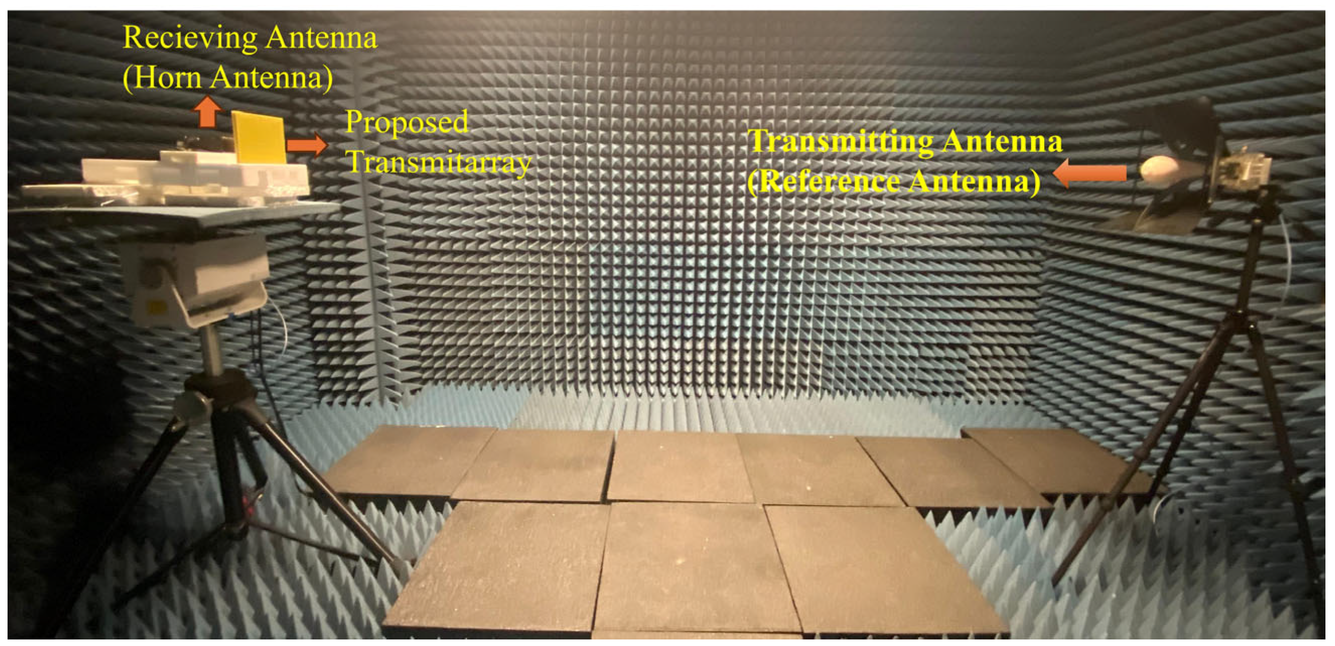
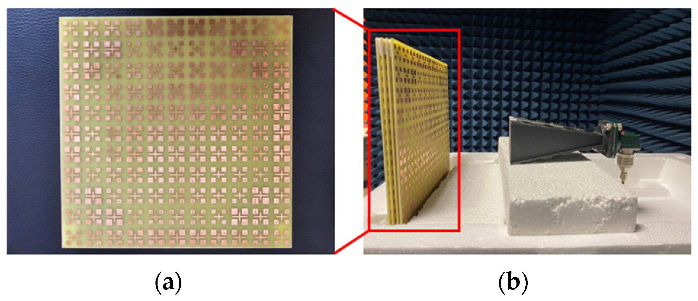
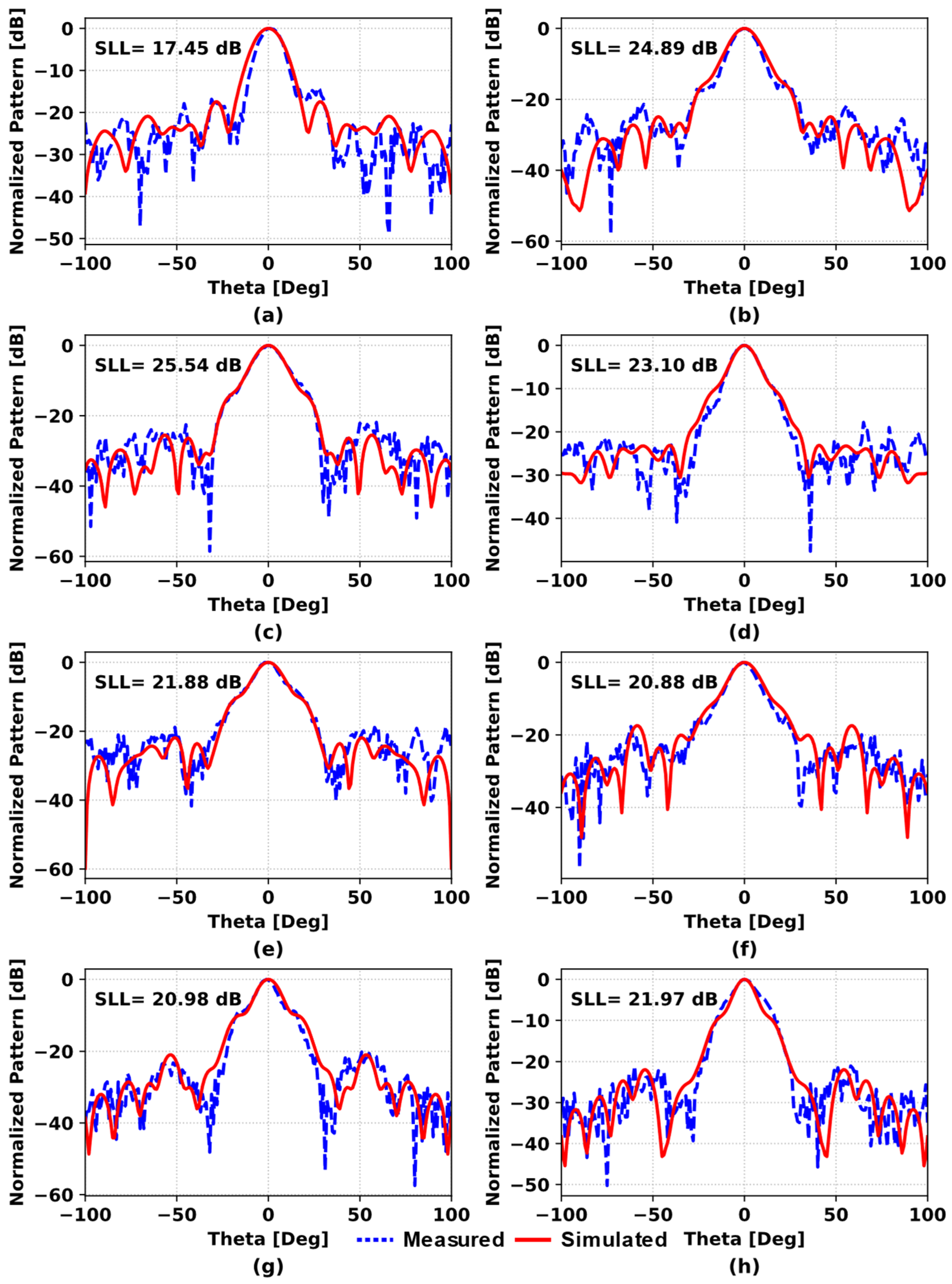
Figure 7 demonstrates the fabricated prototype of the presented transmitarray. Full-wave electromagnetic simulations were performed with CST, and experimental measurements were carried out inside an anechoic chamber to validate the design. Figure 8 presents a comparison of simulation and measurement results at intervals of 0.5 GHz, ranging from 8.5 GHz to 12 GHz with the SLLs.
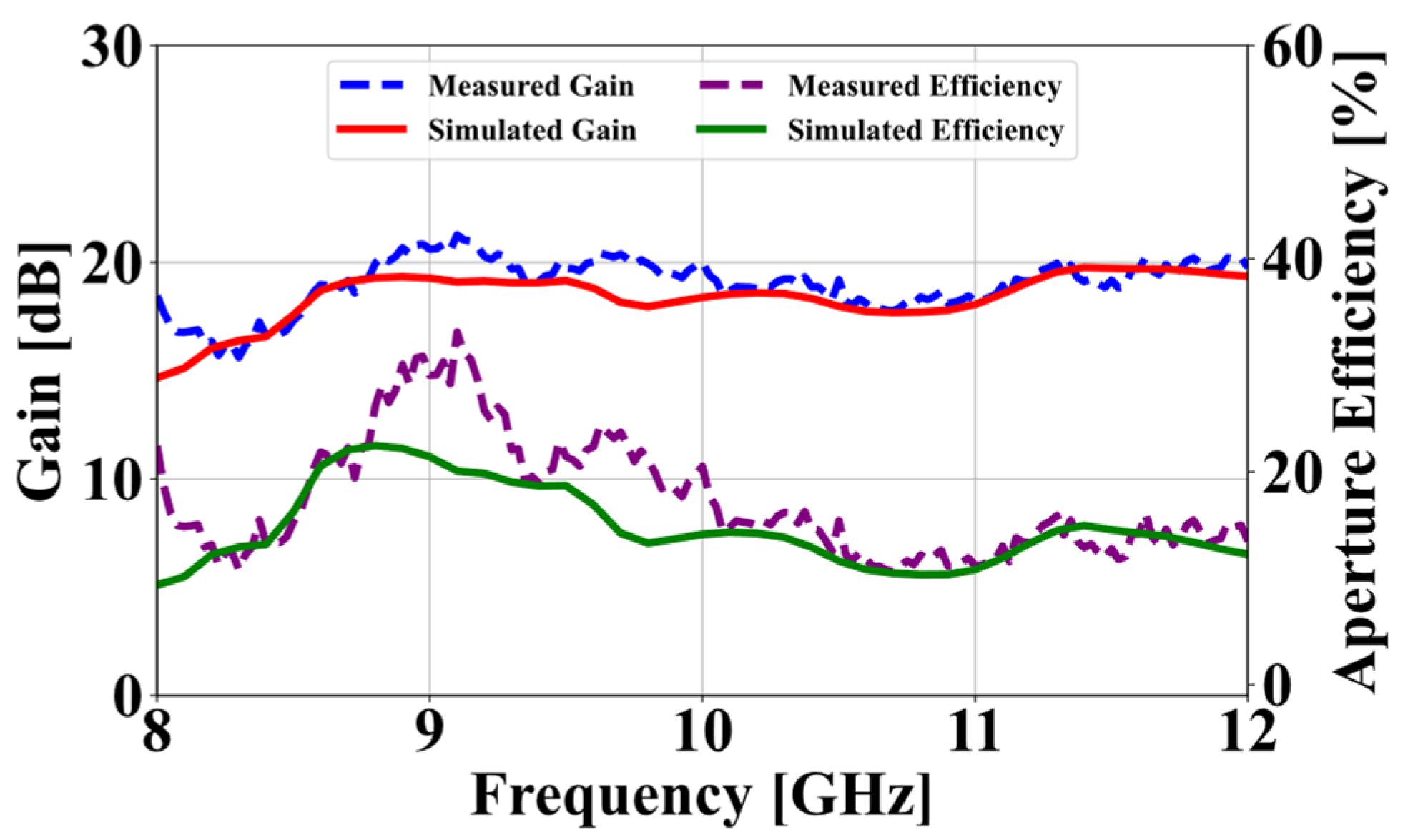
Another key measurement for the fabricated structure is the maximum gain values. The 1 dB gain bandwidth of the structure is 12.12%, spanning frequencies from 8.56 GHz to 9.67 GHz. The aperture efficiency of the proposed transmitarray was evaluated for both measured and simulated data by applying the formulation in Equation (2); the resulting efficiency curves, together with the corresponding gain responses, are depicted in Figure 9.
n a p = G D m a x     D m a x = 4 π A λ 0 2
Here, G signifies the antenna gain, Dmax indicates the peak directivity, A corresponds to the physical aperture area and λ 0 denotes the wavelength in free space.
In examining Equation (2), even small differences in gain values between measurement and simulation results significantly impact aperture efficiency due to the influence of gain in the efficiency calculation. This effect is the primary reason for the discrepancies observed in Figure 9. Table 1 presents a performance comparison of this study with other studies in the literature based on various attributes.
Upon reviewing Table 1, it becomes evident that the presented transmitarray antenna design has advantages over previous studies, including a broader 1-dB and 3-dB bandwidth, a more compact aperture size, and cost-effectiveness, although it is disadvantaged in terms of aperture efficiency. This drawback primarily arises from the use of FR-4 as the dielectric layer, which exhibits losses at the relevant frequencies. Additionally, using FR-4 as the dielectric and manufacturing the prototype with standard production dimensions significantly reduces the overall cost of the study. Also, proposed transmitarray has an SLL of 24.89 dB in the E-planes at 9 GHz.
A folded transmitarray is realized by inserting a phase-gradient reflective surface to generate a virtual focus and shrink the Height to Focal length (H/F) ratio; a center-fed magnetoelectric-dipole element affords independent 1-bit control for dual linear polarizations [28]. A broadband filtering circularly polarized folded transmitarray is implemented in which the top metasurface performs LP to CP conversion, phase compensation and out-of-band spatial filtering to maintain a low profile [32]. A high-efficiency transmitarray uses a two-layer element etched on a compound substrate with horizontally arranged dielectrics; a metal square loop and a patch on opposite faces provide full 360° transmission phase with low loss [33]. An ultrathin metal-only transmitarray is devised using a two-metal-layer polarization-rotation unit cell with perpendicular fan-shaped slits, enabling cross-polar transmission phase tuning at ~0.067λ0 thickness [34]. A dual-band shared-aperture solution co-integrates a Fabry–Perot cavity (X-band) and a folded transmitarray (Ka-band); the aperture acts as PRS at X and polarization grating at Ka, while the ground serves as reflector and reflecting polarizer [35]. A low-profile dual-LP 1-bit transmitarray is obtained via azimuth-insensitive polarization-rotator unit cells, achieving 0.08λ0 thickness with only two metallic layers [36]. A distinct two-layer element on a specially designed substrate with double square loops delivers 360° phase coverage with <3.8 dB amplitude loss and ~44% aperture efficiency near 12 GHz [37].

4. Conclusions

The quad-layer transmitarray using wideband elements is presented for X-band applications. The proposed transmitarray, characterized by low fabrication costs and a simple design, features high gain bandwidth and low SLLs and is realized based on these attributes. It achieves 1 dB and 3 dB gain bandwidths of 12.12% and 49.43%, respectively, with an aperture efficiency of 21.3%. Given these priorities, the modest aperture efficiency is an expected outcome of balancing peak efficiency against wide gain bandwidth and reduced fabrication cost. The measured results are in reasonable agreement with the simulated results. At 9 GHz, simulations indicate a peak gain of 19.28 dB and an E-plane SLL of 24.89 dB. The good agreement between these experimental results and the simulated data confirms the validity of the proposed design. These appealing performances make the proposed design suitable for a wide range of high-gain X-band applications. Future research may focus on improving aperture efficiency by employing low-loss dielectric materials, optimizing the multilayer configuration, or reducing the number of layers, while maintaining the wide bandwidth, low SLL, low cost, and manufacturability demonstrated in this work.

Author Contributions

Conceptualization, M.M., S.Ü. and S.Ç.; methodology, M.M., S.Ü. and S.Ç.; validation, M.M., S.Ü. and S.Ç.; investigation, M.M., S.Ü. and S.Ç.; writing—original draft preparation, M.M., S.Ü. and S.Ç.; writing—review and editing, M.M., S.Ü. and S.Ç.; visualization, M.M., S.Ü. and S.Ç. All authors have read and agreed to the published version of the manuscript.

Funding

This research received no external funding.

Data Availability Statement

Data is contained within the article.

Acknowledgments

The authors acknowledge that this article is based on the first author’s Master’s thesis [38].

Conflicts of Interest

The authors declare no conflicts of interest.

Abbreviations

The following abbreviations are used in this manuscript:
SLLSide Lobe Level
PRSPartially Reflecting Surface
LPLinear Polarization
CPCircular Polarization
EMMPTEExtended Method of Maximum Power Transmission Efficiency
WCMMPTEWeighted Constrained Method of the Maximum Power Transmission Efficiency
PSOParticle Swarm Optimization

References

  1. Yin, T.; Ren, J.; Cai, Y.-M.; Liu, Y.-T.; Zhang, B.; Deng, Y.; Liu, Y.; Yin, Y. Wideband High-Efficiency Transmitarray Antenna Using Compact Double-Layer Dual-Linearly Polarized Elements. IEEE Antennas Wirel. Propag. Lett. 2023, 22, 2372–2376. [Google Scholar] [CrossRef]
  2. Song, C.; Pan, L.; Jiao, Y.; Jia, J. A High-Performance Transmitarray Antenna with Thin Metasurface for 5G Communication Based on PSO (Particle Swarm Optimization). Sensors 2020, 20, 4460. [Google Scholar] [CrossRef]
  3. Malkoç, M.; Ünaldı, S.; Çimen, S. Low Profile mm-Wave Transmitarray Design for 5G Applications. In Proceedings of the 5th International Congress on Contemporary Scientific Research (ICCSR), Kayseri, Turkey, 21–22 April 2024. [Google Scholar]
  4. Dai, X.; Wu, G.-B.; Luk, K.-M. A Wideband Circularly Polarized Transmitarray Antenna for Millimeter-Wave Applications. IEEE Trans. Antennas Propag. 2023, 71, 1889–1894. [Google Scholar] [CrossRef]
  5. Hu, H.-T.; Chan, K.F.; Chan, C.H. Low-Profile Circular-Polarized Filtering Transmitarray Antenna in V-Band. IEEE Trans. Antennas Propag. 2024, 72, 938–943. [Google Scholar] [CrossRef]
  6. de Kok, M.; Vertegaal, C.J.C.; Smolders, A.B.; Johannsen, U. A 34- to 36-GHz Active Transmitarray for Ka-Band Tracking Radar Using 5G Tx/Rx Beamforming ICs: Design and 64-Element Demonstrator. IEEE Trans. Antennas Propag. 2023, 71, 3260–3272. [Google Scholar] [CrossRef]
  7. Yi, X.-J.; Su, T.; Wu, B.; Chen, J.-Z.; Yang, L.; Li, X. A Double-Layer Highly Efficient and Wideband Transmitarray Antenna. IEEE Access 2019, 7, 23285–23290. [Google Scholar] [CrossRef]
  8. Belen, M.A.; Caliskan, A.; Koziel, S.; Pietrenko-Dabrowska, A.; Mahouti, P. Optimal Design of Transmitarray Antennas via Low-Cost Surrogate Modelling. Sci. Rep. 2023, 13, 15044. [Google Scholar] [CrossRef] [PubMed]
  9. Lei, H.; Jia, Y.; Chen Zhong, Y.; Liu, Z.; Shi, G.; Liu, Y. A Low-Profile Metal-Only Folded Transmitarray Antenna Based on Asymmetric Transmission Chiral Metasurface. IEEE Trans. Antennas Propag. 2024, 72, 9480–9485. [Google Scholar] [CrossRef]
  10. Li, M.-Y.; Ban, Y.-L.; Yan, F.-Q. Wideband Low-Profile Ku-Band Transmitarray Antenna. IEEE Access 2021, 9, 6683–6688. [Google Scholar] [CrossRef]
  11. Wu, F.; Wang, J.; Xiang, L.; Hong, W.; Luk, K.-M. A Wideband Dual-Polarized Magneto-Electric Dipole Transmitarray with Independent Control of Polarizations. IEEE Trans. Antennas Propag. 2022, 70, 8632–8636. [Google Scholar] [CrossRef]
  12. Nguyen, B.D.; Nguyen, M.T.; Van, V. An Efficient Approach for Designing Ultrathin Transmitarray Antennas Based on Equivalent Circuit Analysis. IEEE Trans. Antennas Propag. 2024, 72, 5810–5821. [Google Scholar] [CrossRef]
  13. Song, L.-Z.; Qin, P.-Y.; Guo, Y.J. A High-Efficiency Conformal Transmitarray Antenna Employing Dual-Layer Ultrathin Huygens Element. IEEE Trans. Antennas Propag. 2021, 69, 848–858. [Google Scholar] [CrossRef]
  14. Derafshi, I.; Komjani, N. A New High Aperture Efficiency Transmitarray Antenna Based on Huygens Metasurfaces. IEEE Trans. Antennas Propag. 2022, 70, 5458–5467. [Google Scholar] [CrossRef]
  15. Wang, X.; Qin, P.-Y.; Song, L.-Z.; Jin, R.; Guo, Y.J. Tightly Coupled Huygens Element-Based Conformal Transmitarray for E-Band Airborne Communication Systems. IEEE Trans. Antennas Propag. 2023, 71, 2467–2475. [Google Scholar] [CrossRef]
  16. Li, T.-J.; Wang, G.-M.; Li, H.-P.; Hou, H.-S. Circularly Polarized Double-Folded Transmitarray Antenna Based on Receiver-Transmitter Metasurface. IEEE Trans. Antennas Propag. 2022, 70, 11161–11166. [Google Scholar] [CrossRef]
  17. Wang, Y.; Xu, S.; Yang, F.; Werner, D.H. 1 Bit Dual-Linear Polarized Reconfigurable Transmitarray Antenna Using Asymmetric Dipole Elements with Parasitic Bypass Dipoles. IEEE Trans. Antennas Propag. 2021, 69, 1188–1192. [Google Scholar] [CrossRef]
  18. Moon, B.; Oh, J. FSS-Enhanced Quasi-Optical Dielectric Measurement Method for Liquid Crystals in Sub-THz Band. IEEE Antennas Wirel. Propag. Lett. 2023, 22, 3062–3066. [Google Scholar] [CrossRef]
  19. Zhang, Z.; Li, X.; Sun, C.; Liu, Y.; Han, G. Dual-Band Focused Transmitarray Antenna for Microwave Measurements. IEEE Access 2020, 8, 100337–100345. [Google Scholar] [CrossRef]
  20. Li, W.; Wang, Y.; Sun, S.; Shi, X. An FSS-Backed Reflection/Transmission Reconfigurable Array Antenna. IEEE Access 2020, 8, 23904–23911. [Google Scholar] [CrossRef]
  21. Luo, Q.; Gao, S.; Sobhy, M.; Yang, X. Wideband Transmitarray with Reduced Profile. IEEE Antennas Wirel. Propag. Lett. 2018, 17, 450–453. [Google Scholar] [CrossRef]
  22. Wu, R.Y.; Li, Y.B.; Wu, W.; Shi, C.B.; Cui, T.J. High-Gain Dual-Band Transmitarray. IEEE Trans. Antennas Propag. 2017, 65, 3481–3488. [Google Scholar] [CrossRef]
  23. Reis, J.R.; Caldeirinha, R.F.S.; Hammoudeh, A.; Copner, N. Electronically Reconfigurable FSS-Inspired Transmitarray for 2-D Beamsteering. IEEE Trans. Antennas Propag. 2017, 65, 4880–4885. [Google Scholar] [CrossRef]
  24. Sun, S.; Wang, M.; Wen Cheng, Z.; Jun Cui, T.; Ma, H.F. A Dual-Band Circularly-Polarized Transmitarray Antenna with Simultaneous Low Side-Lobe and Cross-Polarization Level. IEEE Open J. Antennas Propag. 2024, 5, 1758–1764. [Google Scholar] [CrossRef]
  25. Dong, Y.; Cai, X.; Wen, G. Circularly Polarized Antenna Array with Suppressed Sidelobes for Electronic Toll Collection. IEEE Antennas Wirel. Propag. Lett. 2022, 21, 988–992. [Google Scholar] [CrossRef]
  26. Dong, Y.; Cai, X.; Geyi, W. A Weighted Method for Multibeam Synthesis with Controllable Gain and Sidelobe Suppression. IEEE Trans. Antennas Propag. 2025, 73, 5291–5299. [Google Scholar] [CrossRef]
  27. Cai, X.; Zhao, Q.; Xu, P.; Geyi, W. Synthesis of Cosecant-Squared Pattern with a Compact Linear Array Using the Extended Method of Maximum Power Transmission Efficiency. IEEE Antennas Wirel. Propag. Lett. 2025, 24, 863–867. [Google Scholar] [CrossRef]
  28. Xiang, B.-J.; Luk, K.-M. A Wideband Dual-Linearly Polarized Folded ME-Dipole Transmitarray Antenna with Low H/F Ratio. IEEE Trans. Antennas Propag. 2024, 72, 466–475. [Google Scholar] [CrossRef]
  29. Chatterjee, S.; Gupta, Y.; Maulik, A.; Bhattacharyya, S. An Optimized Phase-Controlled Metasurface-Based Low-Profile Folded Transmitarray (FTA) Antenna. IEEE Trans. Antennas Propag. 2025, 73, 3316–3321. [Google Scholar] [CrossRef]
  30. Lee, J.-G.; Lee, J.-H. Low-Profile High-Efficiency Transmitarray Antenna for Beamforming Applications. Electronics 2023, 12, 3178. [Google Scholar] [CrossRef]
  31. Reis, J.R.; Vala, M.; Caldeirinha, R.F.S. Review Paper on Transmitarray Antennas. IEEE Access 2019, 7, 94171–94188. [Google Scholar] [CrossRef]
  32. Jia, Q.-S.; Zhang, W.-H.; Han, X.; Huang, Y.-M.; Ding, S.; Wang, B.-Z.; Bozzi, M. A Broadband Filtering Circularly Polarized Folded Transmitarray Antenna Based on Metasurface. IEEE Antennas Wirel. Propag. Lett. 2023, 22, 2357–2361. [Google Scholar] [CrossRef]
  33. Tian, C.; Zhao, G.; Du, R.-N.; Zhang, Z.; Wang, Y.-W. A High Efficiency Transmitarray Using Two-Layer Elements Etched on Compound Substrate. IEEE Access 2022, 10, 40073–40078. [Google Scholar] [CrossRef]
  34. Song, L.; Wang, Y.; Guo, L. A Low-Cost Ultrathin Metal-Only Transmitarray Antenna at X-Band. Antennas Wirel. Propag. Lett. 2024, 23, 1443–1447. [Google Scholar] [CrossRef]
  35. Gao, S.; Wong, H. Design of a Dual-Band Shared-Aperture Antenna Combining Fabry–Perot Cavity and Folded Transmitarray for X- and Ka-Bands. IEEE Trans. Antennas Propag. 2024, 72, 323–331. [Google Scholar] [CrossRef]
  36. Dicandia, F.A.; Genovesi, S. Low Profile Dual Linearly Polarized 1-Bit Transmitarray Exploiting Two Metallic Layers. IEEE Access 2024, 12, 56872–56879. [Google Scholar] [CrossRef]
  37. Tian, C.; Lu, Y.-Q.; Zhao, G.; Jiao, Y.-C.; Guo, L.-X. Double-Layer Transmitarray Antenna Using Specially Designed Substrate. IEEE Antennas Wirel. Propag. Lett. 2022, 21, 441–445. [Google Scholar] [CrossRef]
  38. Malkoç, M. X ve Ka Bant Uygulamaları için Yüksek Kazanç Bant Genişliğine Sahip İleti Dizi Anten Tasarımları. Master’s Thesis, Bilecik Şeyh Edebali University, Bilecik, Turkey, 2024. [Google Scholar]
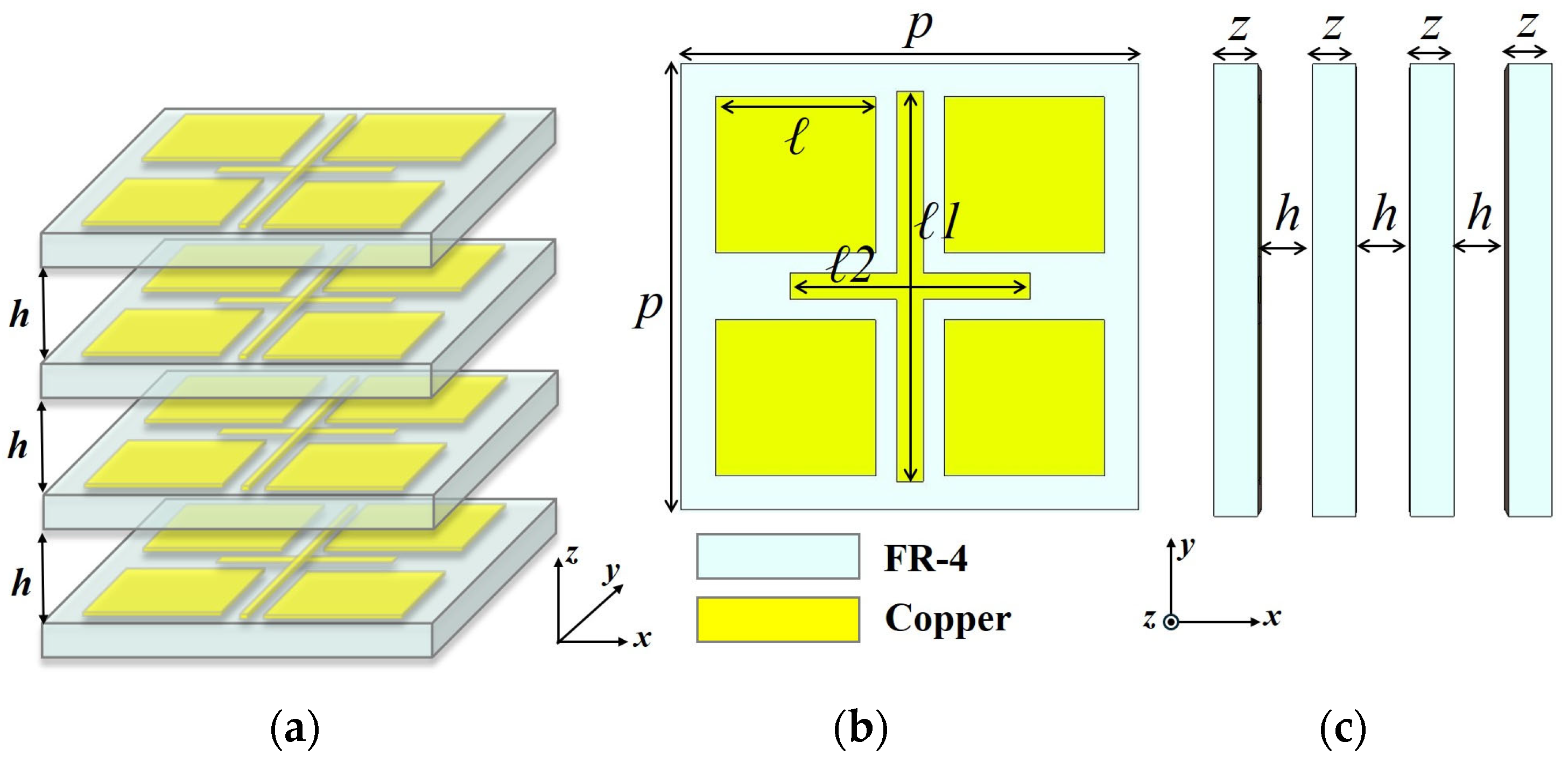
Figure 1. Unit cell structure: (a) Perspective view, (b) top view, (c) side view.
Electronics 14 04044 g001
Figure 2. Normalized transmission coefficients in terms of l 1 at 9 GHz ( l 1 is swept from 8 to 15 mm).
Electronics 14 04044 g002
Figure 3. Comparison of transmission phase at 9 GHz vs. l 1 (2/3/4-layer).
Electronics 14 04044 g003
Figure 4. Transmission phase requirement for each cell based on its position within the antenna aperture.
Electronics 14 04044 g004
Figure 5. Simulated model of the 11   ×   11 transmitarray with horn feed.
Electronics 14 04044 g005
Figure 6. Anechoic chamber and the measurement setup.
Electronics 14 04044 g006
Figure 7. Fabricated prototype of the presented transmitarray (a) front view, and (b) perspective view with horn antenna.
Electronics 14 04044 g007
Figure 8. Simulated and measured radiation patterns in the xz-plane at (a) 8.5 GHz, (b) 9 GHz, (c) 9.5 GHz, (d) 10 GHz, (e) 10.5 GHz, (f) 11 GHz, (g) 11.5 GHz and (h) 12 GHz.
Electronics 14 04044 g008
Figure 9. Measured and simulated results of gain and aperture efficiency for the proposed transmitarray.
Electronics 14 04044 g009
Table 1. Comparison between the proposed and previously reported wideband transmitarray antennas.
Ref.Freq.
(GHz)
Number of Metallic LayersF/DUnit Cell Dimension
(λ0)
Aperture Size
(λ0)
Phase Range
(°)
Via1-dB/3-dB Gain BW
(%)
Aperture Efficiency
(%)
SLL
(dB)
[28]2620.40.569.021-BitYes12 (1-dB)
26 (3-dB)
20Not Specific
[32]1030.250.4710.7360No24.5 (3-dB)40<25
[33]1021.270.326.08360No7.5 (1-dB)58.5Not Specific
[34]1020.640.0679.5360No7 (1-dB)4220.5
[35]930.560.5412.962-BitNo8.1 (1-dB)45<15
[36]821.50.21Not Specific1-BitYes16.5 (3-dB)30.4<15.3
[37]1221.40.525.72360No5.4 (1-dB)4413.4
This Work940.530.515.61360No12.12 (1-dB) 49.43 (3-dB)21.324.89
Disclaimer/Publisher’s Note: The statements, opinions and data contained in all publications are solely those of the individual author(s) and contributor(s) and not of MDPI and/or the editor(s). MDPI and/or the editor(s) disclaim responsibility for any injury to people or property resulting from any ideas, methods, instructions or products referred to in the content.