Abstract
Chaos-based wireless communication systems can enhance the physical-layer security of IoT devices, but their reliability depends on stable chaotic behavior under real conditions. We investigate a modified Colpitts oscillator with a tunable base bias voltage, introduced as an independent control parameter to flexibly adjust nonlinear regimes. Using numerical studies, SPICE simulations, and hardware experiments, we show that simplified numerical models predict only a DC offset shift, whereas realistic implementations reveal qualitative changes in the dynamics, highlighting the need for experimental validation. We further demonstrate hybrid synchronization between the analog oscillator and an FPGA-based digital model. Despite model simplifications and non-idealities, synchronization is successfully achieved using the Pecora–Carroll method, showing that preserving the core dynamic structure is more critical than exact waveform replication. These results clarify the constraints of idealized models for predicting dynamical patterns while confirming the robustness of hybrid synchronization for secure, resource-constrained communication systems.
1. Introduction
The adoption of Internet of Things (IoT) devices in various industry sectors brings substantial improvements in energy efficiency, effective resource allocation, the creation of smart environments, and the monitoring of critical infrastructure. The typical IoT architecture includes sensors and/or actuators controlled by an embedded system located in some physical environment, such as soil, water, human body, building, or industrial facility. A node also has a communication module that enables data transfer and remote control. Wireless communications are exploited as many IoT edge modules are implemented in locations with economically unfeasible wiring installation. The choice of wireless communication technology depends on the distance between communicating modules, the amount of information, the required data rate, the available electrical energy, and the existing infrastructure [1,2]. However, wirelessly connected modules are vulnerable to attacks like eavesdropping, node capture, malicious fake node, replay, and timing attacks [3]. So, additional measures must be taken to ensure confidentiality, data integrity, and availability. Unfortunately, in most cases, sensor nodes are constrained in terms of computational power and energy, and thus cannot implement traditional encryption protocols. To overcome this issue, lightweight cryptography aimed at implementation in IoT is under intensive research and development [4,5]. Additional technology that can enhance the security of IoT networks at the physical level is the deployment of chaos-based communication systems [6].
The chaos phenomenon is observed in nonlinear active electronic circuits producing oscillations. Current and voltage signals in chaotic oscillators are deterministic, governed by a system of nonlinear differential equations, but are characterized by a narrow self-correlation function and a wide spectrum. Also, chaotic systems are extremely sensitive to initial conditions and parameter variations. This means that two electronic circuits built with the same model components may produce different, uncorrelated signals [7]. The unpredictability of chaotic signals makes them a potential candidate for secure communication systems [8]. A vast number of scientific papers are devoted to the development of communication systems that exploit chaos in different ways. In general, chaos-based communication systems can be classified into two main categories: coherent and non-coherent. In a coherent method, the receiver must reproduce the chaotic signal to recover the transmitted message accurately, meaning the transmitter’s and receiver’s chaos generators must be synchronized to derive identical waveforms. Meanwhile, in non-coherent systems, demodulation is performed based only on processing the received signal without synchronization with the transmitter’s chaos generator. Coherent communication techniques offer higher security levels but are sensitive to synchronization issues in noisy channels [9].
Nevertheless, the implementation of chaotic signals in communication systems has remained an active area of research for several decades, yet many challenges still need to be addressed. Researchers have recently proposed various designs of promising chaos-based communication systems using analog and discrete realizations of chaotic oscillators. In [10], the modulation is achieved by changing the numerical integration operator in discrete chaotic maps obtained by the generalized explicit second-order Runge–Kutta solver. The authors experimentally verified the performance of the proposed system, showing high noise immunity and strong confidentiality. The quadrature chaos shift keying (QCSK) communication system, which employs simple, low-cost analog chaotic oscillators, is proposed in [11]. This study outlines the importance of synchronization signal choice to achieve a better BER performance and signifies the need for a threshold-based correction mechanism to compensate for correlation coefficient disparities at higher signal-to-noise ratio (SNR) values. In publications [10,12], a comprehensive characterization of a chaotic oscillator is performed before integrating it into a communication system. Such analysis is mandatory, as different parameters of a real circuit and a mathematical model implemented in a digital device strongly affect the dynamics of an oscillator. For example, results presented in [13] demonstrate that there are regions of periodic behavior for a specific set of capacitor values instead of the expected chaotic mode. Component parameter variations are natural due to production processes, temperature, bias, and other factors. However, they can pose a significant challenge to the practical integration of analog chaotic oscillators in IoT devices. A good option is to place an additional voltage source in an oscillator’s circuit to enable dynamics adjustment during the operation, as manual passive component tuning is impractical and time-consuming [13]. Two main reasons exist for incorporating voltage or current sources in chaotic oscillators. The first is the direct current (DC) offset tuning of signals observed in a nonlinear dynamic system, as shown in [14]. The second is the detailed analysis of chaotic oscillators to reveal hidden attractors and multistability, as described in [15,16]. Multistability is another feature that characterizes chaotic oscillators and can either increase potential application areas or introduce new challenges, particularly when transitions between modes of operation are unwanted [17]. Considering the dynamic behavior of relatively simple chaotic oscillators like Colpitts, it can be concluded that a comprehensive analysis of a chaotic oscillator is needed before its deployment in a communication system. Moreover, synchronization between drive and response chaotic oscillators must be tested for different operating conditions and SNR values, as the coherent detection method strongly depends on synchronization.
Complete synchronization is the easiest way to synchronize two identical electronic oscillators, which was first introduced in [18]. In the literature, it is often called the Pecora–Carroll synchronization method, and a good example of practical realization of this method for the Vilnius oscillator is given in [19]. In addition, other types of synchronization are observed in chaotic systems, like lag, generalized, and phase synchronization [20].
Using simple and cheap analog oscillators is advantageous for IoT edge sensor nodes, as it enables enhanced security for resource-constrained devices. In contrast, gateways—where power and computational resources are less restricted—can use more sophisticated devices like field-programmable gate array (FPGA) and system on a chip (SoC), implementing complex signal processing techniques. On the other hand, using multiple reconfigurable analog oscillators on gateway boards may be challenging in terms of reliability and ease of use. To address these limitations, this work proposes a hybrid synchronization approach that enables coherent, chaos-based communication between digital gateway and sensor nodes employing analog chaotic oscillators. In this article, by hybrid synchronization, the authors understand the complete alignment between the dynamics of analog oscillators and their mathematical model implemented on an FPGA. Synchronization is bidirectional, meaning analog and discrete oscillators can be set as drive (master). The feasibility of this concept was previously demonstrated for the Vilnius and RC oscillators using Euler–Cromer numerical integration methods implemented in fixed-point arithmetic [21]. The obtained results demonstrate a high correlation between signals of synchronized oscillators and the flexibility of discrete models.
In this work, we extend the concept of hybrid synchronization by focusing on the nonlinear dynamics and FPGA-based discrete modeling of a modified Colpitts chaotic oscillator with a tunable base bias. We analyze the impact of component variations—especially capacitors and bias voltages—on the oscillator’s behavior through numerical simulations, SPICE-level modeling, and physical hardware testing. A discrete implementation of the oscillator is developed using an Euler–Cromer integration scheme and tested for synchronization with its analog counterpart.
Although the chaotic dynamics of the Colpitts oscillator have been studied for several decades, our work introduces two important new aspects. First, we systematically examine the influence of an independently controlled base bias voltage across three levels of modeling: simplified mathematical equations, SPICE simulations, and hardware experiments. This multi-level comparison shows how idealized models may miss qualitative behaviors that appear in real circuits, which has not been addressed in earlier works. Second, we demonstrate hybrid synchronization for the first time between a biased analog Colpitts oscillator and its FPGA-based digital counterpart. This highlights not only the theoretical properties of chaos but also its practical applicability in resource-constrained secure communication systems. Thus, the contribution lies in the combination of tunable bias control, model-to-hardware comparison, and hybrid synchronization, which together extend beyond prior studies of Colpitts oscillators.
The structure of the article is as follows: Section 2 introduces the Colpitts chaotic oscillator and presents the mathematical model, including the effect of bias voltage tuning. Section 3 provides a detailed numerical study, including bifurcation analysis and parameter sensitivity. Section 4 describes the analog implementation using SPICE simulations and hardware prototyping. Section 5 presents the digital implementation and fixed-point modeling on an FPGA. Section 6 evaluates the hybrid synchronization between analog and discrete realizations. Finally, Section 7 discusses the results and their implications and outlines potential directions for future work.
2. Colpitts Chaotic Oscillator
2.1. Circuit and Mathematical Model
Commonly employed for radio frequency (RF) signal generation, the Colpitts oscillator exhibits chaotic behavior under certain component values [11,22,23]. The schematic of a Colpitts oscillator demonstrating chaotic dynamics is shown in Figure 1. This oscillator consists of a bipolar junction transistor (BJT) operating in its active region, along with an inductance and a capacitive divider, formed by and and providing positive feedback to sustain oscillations. The inductor , in series with its internal resistance , together with a bias resistor , completes the circuit loop. The DC supply voltages and provide proper biasing for the transistor.
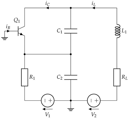
Figure 1.
Schematic of the Colpitts chaotic oscillator [22].
Applying Kirchhoff’s circuit laws to this topology yields the following set of nonlinear differential equations governing the oscillator’s dynamics [22]:
where and denote the voltages across capacitors and , respectively; is the current through the inductor; and and are the base and collector currents of the transistor.
In these equations, and are nonlinear functions describing the transistor’s operation. The transistor alternates between the forward-active region and cutoff. A piecewise-linear approximation for the transistor currents is given by
where is the base-emitter threshold voltage, is the small-signal on-resistance of the base-emitter junction, and is the transistor’s forward current gain.
Chaos emerges in this oscillator from the interplay between the transistor’s nonlinear characteristics and the energy exchange among the reactive components (, , and ). This interchange produces an effective third-order nonlinear system capable of exhibiting complex dynamics. For instance, one set of component values that yields chaotic oscillations is V, V, , H, nF, nF, and , using a transistor such as the 2N3904. Under these conditions, the circuit oscillates with a fundamental frequency of approximately 96.8 kHz.
2.2. Bias Voltage Tuning
This work introduces a modification to the Colpitts chaotic oscillator by incorporating a DC bias source at the BJT transistor’s base. Adding an independent voltage source at the base of (see Figure 2) significantly alters the behavior of the system. In the conventional Colpitts oscillator, the base is biased through a resistor from a DC supply, and the feedback loop consists of the inductor (with series resistance ) and the capacitive divider –. In such a configuration, the capacitor voltage directly influences the base-emitter junction, resulting in a relatively straightforward third-order nonlinear system model.
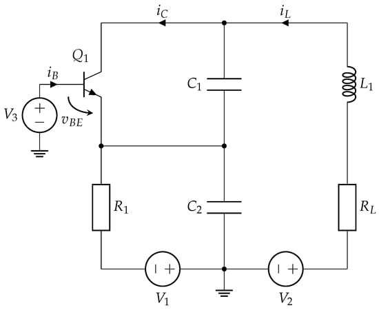
Figure 2.
Modified Colpitts chaotic oscillator with an added base-bias voltage .
In the modified configuration, the base is no longer biased solely through ; instead, it is driven by the dedicated source . This change effectively decouples from the base-emitter voltage and alters the mathematical structure of the system. Consequently, the base-emitter voltage is now expressed as
which expresses as the difference between the bias source and the capacitor voltage .
This shift in bias modifies the circuit’s governing equations, although the system remains a third-order oscillator with state variables , , and . The resulting differential equations of the modified Colpitts oscillator are given by
where is the voltage across , is given by (4), is the inductor current, and and are the base and collector currents, respectively.
To model the transistor’s nonlinear behavior in this biased configuration, we continue to use a piecewise-linear approximation for the base current that accounts for the base-emitter threshold:
where is the base-emitter junction’s threshold voltage, is the effective on-resistance of that junction when forward-biased, and is the forward current gain. Introducing the bias shifts the transistor’s operating point, thereby making the base-emitter junction more (or less) sensitive to changes in depending on the magnitude and polarity of .
This adjustment of the base bias affects the onset of conduction in the transistor and the nature of the nonlinear feedback responsible for chaos. By shifting the transistor’s conduction region through , the system’s bifurcation structure is altered, allowing one to tune the characteristics of chaotic oscillations. In the mathematical model, enters as an additional offset in the base–emitter voltage, which shifts the equilibrium point of the transistor without changing the system order or introducing new nonlinearities in the simplified equations. Thus, provides an independent control parameter that decouples biasing from the feedback network, enabling flexible, real-time tuning of the oscillator’s operating regime without hardware modifications. This extra degree of freedom enhances design flexibility and ensures adaptive control of chaotic dynamics, which has potential applications in secure communications, sensing, and programmable chaotic signal generation.
3. Numerical Study
The first step in investigating the applicability of the proposed modified Colpitts oscillator for chaotic communication systems is to carry out a detailed numerical analysis. This study aims to predict the circuit’s possible dynamical behaviors under parameter variation. Such analysis serves two key purposes: on the one hand, it enables designers to intentionally adjust parameters to achieve desired nonlinear modes; on the other hand, it helps anticipate how the circuit’s dynamics may shift due to component tolerances, ageing, thermal effects, or other physical processes.
Section 2 defines the system’s range of parameters under study. Introducing the new voltage source could change the system’s dynamics. Thus, the effects of on the phase portraits and bifurcation diagrams are studied first.
Figure 3 represents the phase portraits of the system, corresponding to three different values of V. It could be clearly seen that the introduction of additional biasing voltage to the transistor base, according to Model (5), does not cause significant qualitative changes in the system’s dynamics. The attractor shifts along the y-axis, demonstrating the well-described offset-boosting effect [24].
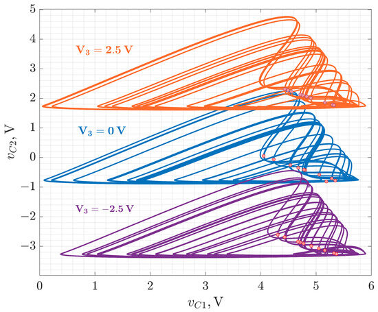
Figure 3.
Phase portraits of the Colpitts oscillator with introduced biasing voltage . Parameters of the system are as follows: V, Ω, , µH, Ω, nF, Ω, V, V.
In the piecewise-linear mode of the BJT, the introduction of an additional voltage source , connected between the base and ground, does not significantly affect the system’s qualitative dynamics. This could be explained by the fact that enters the model primarily through the base-emitter voltage . Mathematically, adds a constant offset to , compensating for a similar shift in the (corresponding to the base-emitter voltage). As long as the condition is regularly satisfied during oscillations, the circuit’s switching behavior and overall nonlinear dynamics remain unchanged. Thus, acts as a vertical shift in the phase space without altering the structure of the attractor.
It has been demonstrated that the dynamics of the Colpitts oscillators are highly dependent on the values of their capacitors [13]. Thus, to consider this aspect, we obtain the bifurcation diagrams for the selected range of capacitor values nF. This analysis allows minimization of the sensitive dependence of the generated signals on the capacitor tolerances or ageing effects, selecting the values in the area of robust chaotic oscillations.
Figure 4 presents a set of bifurcation diagrams of the modified Colpitts oscillator obtained by varying the capacitors and values in the range of 30 nF to 60 nF. The results are shown for three different bias voltage values: V.
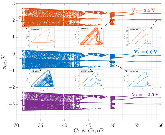
Figure 4.
The bifurcation diagrams for the Colpitts chaotic oscillator with the following parameters of the system: V; Ω, , µH, Ω, Ω, V, V, nF.
Diagrams presented in Figure 4 illustrate the system’s long-term behavior after transients have decayed, with plotted as the bifurcation observable state variable.
The most prominent feature of all diagrams is that while the change in introduces a vertical shift in the voltage levels (as expected from its role as a bias source between base and ground), it does not alter the qualitative structure of the bifurcation landscape. This indicates that primarily affects the operating point of the active device (transistor), but not the underlying nonlinear dynamics, at least under the simplified transistor models employed.
In contrast, variations in and dramatically affect the oscillator’s behavior. The diagrams exhibit classical period-doubling routes to chaos for higher values of capacitances and sudden jumps from period-1 to chaotic oscillations for lower values of and . Within the chaotic regimes, periodic windows are clearly visible, reflecting islands, where the system temporarily stabilizes into regular oscillations. This complex interplay of order and chaos is a classical feature of low-dimensional nonlinear systems.
It should be noted that in the analysis, it is assumed that both capacitors are degrading at the same rate, which could not be the case in real circuitry. Thus, it would be valuable to identify the dependence of the system’s dynamics for a wide range of and combinations. This can be represented as a two-dimensional bifurcation diagram (Figure 5), where and are chosen as bifurcation parameters and colors indicate periodic or chaotic modes of operation.
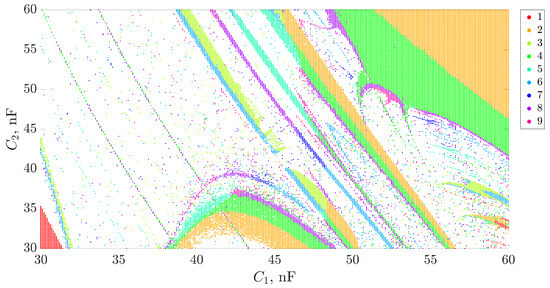
Figure 5.
The bifurcation map for the Colpitts chaotic oscillator with the following parameters of the system: V; Ω, , µH, Ω, Ω, V, V, nF, nF.
To construct the two-dimensional bifurcation maps, the system is numerically integrated using the piecewise-linear transistor model (6), (7). For each pair of , values, a transient is discarded and the steady-state dynamics are sampled using a Poincare section. The resulting time series are then analyzed to detect periodicity: repeated cycles within numerical tolerance are classified as periodic orbits (up to period-9), while irregular non-repeating sequences are classified as chaos. The map is color-coded by periodicity, with the chaotic regime shown in white. This method allows for visualization of the parameter space, detection of bifurcation borders, and regions of robust chaotic oscillations.
The two-parameter bifurcation map in the and plane in Figure 5 reveals a highly sophisticated structure of the oscillator’s dynamic regimes. The diagram shows the dependence of the system’s behavior on simultaneous variation of both capacitances, with each color corresponding to a specific periodicity (from period-1 to period-9). The white regions indicate chaotic behavior, where no closed orbit with a low period can be identified within the tested precision.
Broad zones of chaos are observed to dominate large regions of the parameter space. Yet, they are intersected by narrow, well-organized bands of periodicity, representing classical periodic windows embedded in chaos. These periodic tongues appear in arc-like or diagonal shapes, forming Arnold tongue-like structures and showing the system’s intense sensitivity to slight variations in both capacitances.
The borders between chaotic and periodic regions are sharp, suggesting the presence of bifurcations such as period-doubling, saddle-node, or crisis-induced intermittency. The observed sequence of periodicities—from period-1 up to period-9—indicates multiple routes to chaos, likely dominated by period-doubling cascades in some regions and quasi-periodic transitions in others.
From a practical standpoint, this analysis highlights the importance of precise capacitor selection. Due to the strong sensitivity of the oscillator’s dynamics to capacitance values, even minor deviations arising from manufacturing tolerances or ageing can shift the system into a qualitatively different regime. Such transitions may be undesirable for applications in secure chaotic communication, where unpredictable yet reproducible behavior is desired. Therefore, the capacitor values must be chosen within well-defined intervals that correspond to robust chaotic regimes—regions where chaos persists over a range of parameters, without being interrupted by regular dynamics (e.g., nF in the current case). These findings emphasize the necessity of careful numerical bifurcation analysis in the early design phase to ensure reliable circuit operation in the desired nonlinear regime.
It should be stressed that the results obtained through numerical studies based on simplified piecewise-linear transistor models should not be regarded as an exact design guideline. Instead, they serve as a conceptual framework that depicts the system’s key dynamic behaviors and parameter dependencies under investigation. While these models help identify bifurcation scenarios and estimate chaotic or periodic operation regions, they inherently exclude some more complicated physical interdependencies, such as the Early effect, dynamically varying current gain, parasitic elements, and manufacturing tolerances in semiconductor devices. Therefore, experimental validation remains the definitive standard for analyzing chaotic electronic circuits, as it captures the full complexity of real-world behavior beyond the reach of simplified models.
4. Colpitts Chaotic Oscillator Analog Implementation
The study proceeds with a two-fold investigation comprising SPICE-level circuit simulation and hardware prototype measurements to validate the practical feasibility of the proposed chaos-based oscillator for communication applications. While the numerical analysis in Section 3 provides insight into the system’s dynamic behavior under idealized conditions, the present section focuses on a more implementation-oriented perspective. First, the oscillator is simulated in the LTspice environment using realistic device models to evaluate its performance under near-physical conditions. This is followed by the construction and testing of a laboratory prototype to experimentally verify the key dynamic features predicted by both the numerical and simulation studies.
4.1. Simulation Study
Following the numerical investigation presented in Section 3, the second stage of the analysis involves a time-domain simulation of the modified Colpitts oscillator using the LTspice simulator software version (x64) 17.1.9. This stage aims to evaluate the circuit’s behavior under more realistic conditions by incorporating non-idealities present in commercially available components. While the mathematical model offers valuable insight into the system’s dynamic regimes, the LTspice simulation provides a complementary perspective that bridges theoretical analysis and hardware implementation.
In contrast to the numerical approach, LTspice uses detailed SPICE-level models, particularly for active components such as the BJT. These models account for nonlinearities, parasitic effects, and temperature dependencies, yielding results that are more representative of the physical prototype. Although the simulation does not fully capture all practical factors, it serves as a crucial intermediate validation step, offering a more hardware-faithful approximation of the circuit dynamics.
All component values and operating parameters used in the simulation were consistent with those defined in Section 2. The implementation of the additional DC bias voltage was investigated to evaluate its impact on circuit operation. The effects of the bias voltage were analyzed regarding time-domain signal waveforms and reconstructed phase portraits, allowing direct comparison with the numerical model and subsequent experimental measurements.
In Figure 6, LTspice-simulated attractor projections in the – phase plane for three values of the DC bias voltage V are presented. The results illustrate both vertical translation and deformation of the attractor shape, reflecting the increased realism of the transistor model used in simulation.
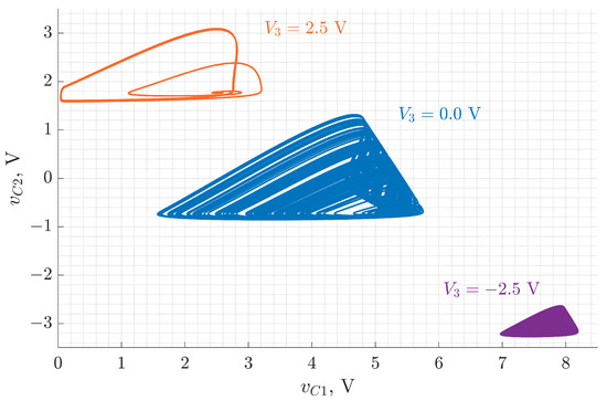
Figure 6.
Phase portraits of the Colpitts oscillator with introduced biasing voltage , obtained in the LTspice simulation.
To evaluate the impact of the DC bias voltage under more realistic conditions, phase portraits were reconstructed from LTspice simulation data for three representative values of . As shown in Figure 6, the attractors undergo a vertical shift in the – plane, consistent with offset-boosting behavior. In addition to translation, the attractor geometry itself changes significantly with bias variation. Unlike the idealized numerical model, which predicts primarily a positional shift, the LTspice results capture more complex dynamic transformations. These differences stem from the high-fidelity transistor model used in the SPICE simulation, which accounts for nonlinear junction behavior, charge storage effects, and other parasitics typically present in hardware implementations.
A set of bifurcation diagrams was generated by launching LTspice simulations from within the MATLAB environment to investigate the influence of capacitor values on the oscillator’s behavior. This approach allowed automated sweeping of and from 30 nF to 60 nF for three different DC bias voltages: V. The state variable was extracted from each simulation after transient effects subsided and used as the bifurcation observable. The resulting diagrams are shown in Figure 7.
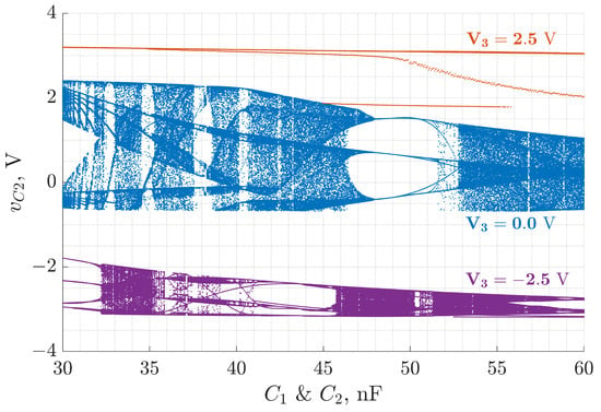
Figure 7.
Bifurcation diagrams of the Colpitts oscillator obtained via MATLAB-controlled LTspice simulations for varying values of nF and three distinct bias voltages: V. The diagrams use as the bifurcation observable after transient decay.
As observed in Figure 7, the application of different values not only vertically shifts the bifurcation structures but also introduces clear variations in their topology and extent. In contrast to the numerically obtained bifurcation diagrams based on idealized models, the LTspice simulations indicate that the bias voltage substantially alters the qualitative nature of the system’s dynamics. This can be attributed to the higher-fidelity transistor modeling in LTspice, which captures junction nonlinearities, charge storage, and region transitions. Consequently, the dynamic response is more sensitive to biasing, resulting in bifurcation diagrams with differing chaotic bandwidths, densities, and bifurcation window structure. These findings emphasize the necessity of accounting for physical device behavior when designing chaos-based systems and highlight specific capacitor regions where robust chaotic oscillation persists under bias variation.
4.2. Prototype
A dedicated printed circuit board (PCB) prototype was developed to experimentally validate the simulation findings and assess the practical behavior of the modified Colpitts oscillator. The oscillator circuit was designed using KiCad software (version 8.0) and manufactured via PCB milling. The board includes two variable resistors, and , which allow manual tuning of the operating point to ensure the oscillator operates within a chaotic regime. The fabricated prototype of the Colpitts chaotic oscillator is shown in Figure 8.
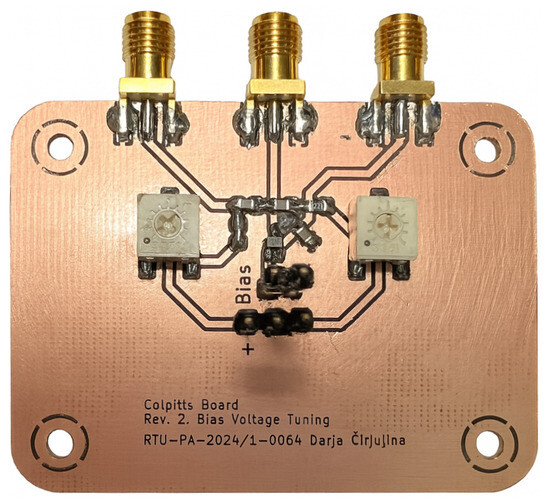
Figure 8.
PCB Design of the Colpitts chaotic oscillator created in KiCad software.
To examine how the base bias voltage affects the circuit’s dynamics in practice, phase portraits were measured from the prototype for five different values of V. For each case, the attractor was reconstructed from voltage measurements of and . Figure 9 presents the results. The blue attractors correspond to the unbiased configuration where the transistor base is directly grounded. The orange attractors represent the behavior when an external DC bias voltage is applied to the base via an additional voltage source.
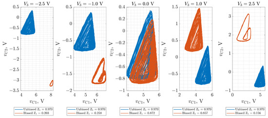
Figure 9.
Experimentally measured attractors from the Colpitts chaotic oscillator prototype for various DC bias voltages . Blue curves represent the unbiased configuration (base grounded); orange curves represent the biased case.
Several observations emerge from Figure 9. First, the attractor exhibits uniform structure when the base is grounded (blue curves). However, once the external voltage source is connected, even when V, the attractor shape shifts. This behavior is attributed to parasitic capacitance and leakage currents introduced by the voltage source’s physical wiring and internal impedance. These parasitics alter the local bias conditions at the transistor base, leading to measurable changes in the oscillator’s state space trajectory.
As is swept across a wider range ( to V), further changes in the attractor shape and position are observed. These variations arise due to the strong dependence of BJT operation on base-emitter voltage. Specifically, the applied bias alters the transistor’s quiescent point, thereby modifying the collector current and consequently the charging dynamics of the capacitors. At higher positive values of , the transistor remains more continuously in its active region. In contrast, strongly negative bias tends to push it closer to the cutoff or saturation, reducing the amplitude and complexity of the oscillations. This is reflected in the attractor compression or separation across voltage levels.
The 0–1 test for chaos (Z1TEST) was applied to the measured voltage signals to quantify these changes [25], and the resulting -values are shown in the figure legend. The test numerically evaluates the degree of chaotic behavior, with values closer to 1 indicating stronger chaotic behavior but values closer to 0 indicating periodic behavior. The results confirm that the biased configurations exhibit reduced or suppressed chaotic dynamics for extreme values, aligning with the observed attractor deformation.
While the general trends observed in the experimental results are consistent with those from LTspice simulations (see Figure 6), clear differences in attractor shape and signal characteristics emerge due to hardware parasitics and real-world component nonidealities. Both simulations and experiments demonstrate that causes not only a vertical shift in the attractor but also a transformation in shape and complexity. However, the experimental results further confirm the importance of parasitic elements and external circuit influences that are not fully captured even by SPICE-level simulations. These findings emphasize the necessity of hardware validation for chaos-based systems, particularly when operated near sensitive bifurcation boundaries.
5. Colpitts Chaotic Oscillator Digital Implementation
The current subsection is devoted to the digital implementation of the Colpitts chaotic oscillator model, breaking down the steps performed to transform the differential equations with an added base-bias voltage (5) for FPGA-based digital design. In the first transformation step, the following dimensionless variables are introduced:
where is the characteristic frequency; is the characteristic impedance; is the dimensionless time. These parameters are then applied to normalize and simplify the equations, resulting in (10). It is important to note that in (10) is taken as 5 V, i.e., the sign is moved from the constant to the equation, for convenience. The goal of applying dimensional normalization is to express the oscillator equations in a dimensionless form suitable for digital implementation on the FPGA. This step reduces the dynamic range of variables, prevents numerical overflow in fixed-point arithmetic, and enables comparison of different oscillators on a common basis. As for the time scale of the dimensionless equations, the characteristic frequency is selected. The fundamental frequency of the Colpitts oscillator can also be used, resulting in the following dimensionless variables:
where is the fundamental frequency; is the equivalent characteristic impedance; is the dimensionless time.
It is important to note that the choice of normalization does not change the dynamics of the oscillator, only the appearance of the equations in dimensionless form. To derive the dimensionless equations, the variables in (8) are used. The fundamental frequency of the Colpitts oscillator can also be utilized, resulting in a different appearance of normalized equations (different coefficients and constants) with preserved dynamics and chaotic attractor. Appendix A elaborates in detail on the difference of normalized equations using (8) and (9) and how this affects the FPGA implementation of the equations.
The variables shown in (11) are introduced in the second transformation step, resulting in simplified normalized equations in (12):
In the following step, the Euler–Cromer numerical integration is applied to acquire the approximate discrete solution for the integration step shown in (13). The Euler–Cromer method was selected as it provides a computationally efficient integrator for oscillatory systems, preserving qualitative behavior (such as amplitude and phase stability) more effectively than the standard forward Euler method [26]. The simplicity of the Euler–Cromer method makes it well suited for discrete hardware implementation. Although higher-order methods such as Runge–Kutta [27] are preferable for obtaining exact trajectories, the Euler–Cromer method preserves the attractor shape—provided that is chosen carefully—which is precisely the requirement for digital hardware implementation.
The piecewise-linear approximation for the base current with the introduced transformations is presented in (14). The resultant difference Equation System (13) can then be implemented in a digital system, since each next value of the state variables is acquired by adding the derivative multiplied by the integration step to the current value of the state variable:
Figure 10 presents the digital design approach for implementing the Colpitts chaotic oscillator difference Equation System (13). The figure demonstrates the design slice for the x state variable, as the approach is identical for the other state variables. The core of the system is the register that updates the state variable x on the rising edge of the clock signal, thus acquiring the current value . To acquire the next value , first, the current values , and are passed to the derivative calculation pipeline. The pipeline takes the current values and constants and performs operations labeled as “Derivative” in (13) for each state variable accordingly. Second, the output of the pipeline is multiplied by the integration step . Finally, the result of the multiplication is added to , thus acquiring . This design is replicated to y and z state variables, with the derivative calculation pipeline being the common block. This design was first proposed in [21] for Vilnius [28] and RC [29] chaotic oscillators and is now applied to the Colpitts chaotic oscillator.
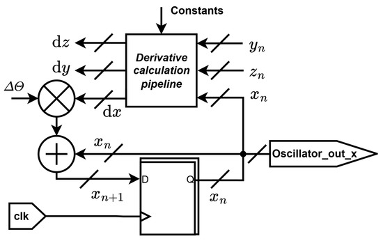
Figure 10.
Digital design slice of the Colpitts oscillator for FPGA implementation.
It is important to note that in this FPGA implementation, the master clock frequency and the numerical integration step are not identical quantities. The FPGA system clock (100 MHz) determines the rate at which arithmetic operations are executed, while is implemented as a constant multiplier in the discretized equations to control the effective integration step size. In this way, can be set independently of the hardware clock, allowing the same FPGA design to emulate different step sizes by adjusting only the scaling constants, thus ensuring flexibility in digital realization. In order to match the analog chaos oscillator, the integration step must be the relation of the scaling frequency to the clock frequency (15).
As the system is implemented in fixed-point arithmetic, the is rounded with the fixed-point precision. A more detailed numerical convergence study, including step size sensitivity and the estimate of the largest Lyapunov exponent, is beyond the scope of this work and will be addressed in future investigations focused specifically on quantitative stability assessment of fixed-point chaotic models.
The derivative calculation pipeline design is addressed next. The “Derivative” part from (13) is shown in (16). The pipeline approach is set to split the mathematical operations with the help of registers. To reduce the number of operations, the nonlinearity is approximated using read-only memory (ROM). The is used in two equations and it is most convenient to form two different ROMs. The first ROM contains . The second ROM contains , as the itself has as input argument.
It is important to note that since the two ROMs contain the bias voltage , new memory data must be created for the specific . Similarly, is stored as a single constant , which must also be updates accordingly. The simplified pipeline is shown in (17).
The design of the memory is depicted in Figure 11. The system is designed in fixed-point arithmetic with an 8-bit-wide integer part and a 14-bi-wide fractional part of the output state variables. The ROMs have a 12-bit address space and store 6-bit-wide integer 16-bit-wide fractional part data. The read address in both ROMs is formed from the state variable by taking 6 integer bits and 6 fractional bits.
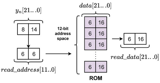
Figure 11.
The ROM design for the Colpits chaotic oscillator FPGA implementation.
The digital design of the Colpitts chaotic oscillator with added base-bias voltage is verified in MATLAB 2023b. Figure 12 presents the – (reflects the –) phase trajectories for three values of the DC bias voltage V. The phase portrait illustrates a completely different behavior of the oscillator model with the applied compared to that shown in Figure 6. This can be attributed to the simplified mathematical model of the transistor considered initially.
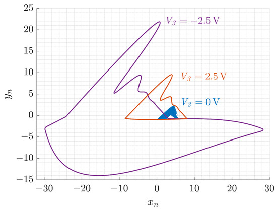
Figure 12.
Phase portraits of the FPGA-based Colpitts oscillator with introduced biasing voltage .
6. Analog–Discrete and Discrete–Analog Synchronization
This section is devoted to experimentally investigating the possibility of the analog–discrete and discrete–analog synchronization between the analog oscillator implemented on the PCB and the discrete oscillator implemented in an FPGA using Very-High-Speed Integrated Circuit (VHSIC) Hardware Description Language (VHDL). The key investigation point is whether the synchronization can be achieved with base-bias voltage added to the analog or the discrete oscillator. As demonstrated previously, the two oscillators exhibit different responses to variations of .
To achieve synchronization, we employ a Pecora–Carroll drive–response scheme in which one measured state of the drive oscillator is injected into the response oscillator each step (state replacement), while the remaining states evolve according to the model dynamics. In practice, we couple via the capacitor-voltage state x with applied normalization as in Section 5.
The discrete–analog synchronization study is presented in Figure 13. The state variables of the FPGA-based chaotic oscillator are , and , while the state variables of the analog oscillator are , and . The discrete–analog synchronization is Pecora–Carroll synchronization, as demonstrated in Figure 13a. The state variable x is chosen as a synchronization signal based on [11]. The FPGA-based oscillator with the applied is the drive system, while the analog oscillator is the response system. The synchronization is evaluated using the Pearson correlation coefficient for , and , .
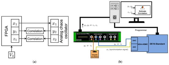
Figure 13.
Discrete–analog Pecora–Carroll synchronization, showing state variables used for synchronization and correlation analysis (a) and experimental setup for synchronization evaluation with different applied to the discrete oscillator (b).
Figure 13b demonstrates the experimental setup used to perform the study. The FPGA-based chaotic oscillator runs on the Terasic DE10-Standard board with the 100 MHz clock frequency. To interface the FPGA-based oscillator, an Terasic ADA-HSMC daughter card is used, providing the two-channel analog-to-digital converter (ADC) as well as the two-channel digital-to-analog converter (DAC). The first DAC channel outputs the synchronization signal, while the other channel outputs the or the signal. The synchronization signal is passed to the analog oscillator implemented on the PCB. The Digilent’s Analog Discovery Pro (ADP3450) is used to record the , and , signals that are then used to estimate the Pearson correlation in MATLAB. The measurements are performed for different values of V applied to the FPGA-based oscillator.
The analog–discrete synchronization study is outlined in Figure 14. The general approach and setup are similar to those in Figure 13; the key difference is that the analog oscillator with the applied is the drive system, while the FPGA-based oscillator is the response system (see Figure 14a). Like in the previous study, the synchronization is evaluated using the Pearson correlation coefficient for , and , .
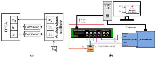
Figure 14.
Analog-discrete Pecora–Carroll synchronization, showing state variables used for synchronization and correlation analysis (a) and experimental setup for synchronization evaluation with different applied to the analog oscillator (b).
Figure 14b demonstrates the experimental setup used for the study. The synchronization signal from the analog chaotic oscillator is passed to the FPGA-based oscillator via the ADC. The DACs output the and state variables of the FPGA-based oscillator. The ADP3450 records the , and , signals that are then used to estimate the Pearson correlation in MATLAB. The measurements are performed for different values of V applied to the analog chaotic oscillator using the waveform generator of the ADP3450.
Table 1 compiles the results of the Pearson’s correlation coefficient fort fort for analog–discrete and discrete–analog synchronizationbase bias voltage . The Pearson’s correlation coefficient for perfectly synchronous signals equals 1, while the Pearson correlation coefficient equals 0 for completely asynchronous signals. The table demonstrates a coefficient of more than 0.9 in most cases, indicating that the chaotic synchronization is achieved despite the different behavior of the analog and FPGA-based chaos oscillators with applied . It is visible that the only case that demonstrates the overall lower correlation coefficient (0.7 to 0.9) is the case of y state variables in the discrete–analog synchronization case. The likely reason for the reduced correlation coefficient lies in the model simplifications, since the discrete model was designed to reproduce the chaotic attractor rather than to precisely match the exact trajectories of the analog chaotic oscillator. Additionally, hardware nonidealities play a significant role, as imperfections in the analog oscillator directly influence its dynamics. Another observation is that applying a negative base-bias voltage results in slightly better synchronization than a positive voltage.

Table 1.
Synchronization evaluation using the Pearson’s correlation coefficient.
The results highlight that synchronization is invariant to the base-bias voltage . The dynamics of the drive oscillator are enforced and the generalized synchronization is achieved, thus not requiring explicit compensation of the mismatch.
7. Discussion
This work investigated the nonlinear dynamics and hybrid synchronization of a modified Colpitts chaotic oscillator with a tunable base bias voltage , potentially enabling effective variation of the oscillator’s behavior, affecting the offset and shape of phase space attractors. A multi-level approach was employed, including numerical bifurcation analysis, SPICE-level circuit simulations, experimental measurements using a custom-built analog prototype, and FPGA-based digital implementation. The central objective was to study the feasibility of achieving synchronization between analog and discrete realizations of the oscillator under varying conditions of base bias voltage, which acts as a control parameter for the system’s dynamic behavior.
The numerical studies, relying on a simplified piecewise-linear model of the transistor, indicated that the application of a DC bias voltage primarily causes an offset in the attractor position within the phase space, without significantly altering the oscillator’s qualitative dynamics. Bifurcation analysis allowed us to identify the sensitivity of the qualitative dynamics on the parameters (e.g., capacitor values) and map the robust chaotic operating regions.
SPICE simulations and practical hardware tests revealed a more dynamically rich behavior. The system’s response to variations in was more complex, with observable attractor deformation and even partial suppression of chaotic behavior under extreme bias values. The observed differences highlight the limitations of idealized models and emphasize the influence of physical parasitics, realistic transistor behavior, and implementation-specific effects on the circuit’s dynamics.
A digital implementation of the Colpitts oscillator was realized on an FPGA using fixed-point arithmetic and the Euler–Cromer integration scheme. While this implementation enabled precise control and reproducibility, it inevitably introduced simplifications due to model discretization and limited numerical resolution. As a result, the discrete oscillator did not replicate the analog dynamics exactly, particularly in how it responded to changes in the base bias voltage. Despite these differences, synchronization was successfully achieved between the analog and discrete systems, both when the discrete oscillator acted as the drive system (discrete–analog case) and when it served as the response system (analog–discrete case).
This result is of particular importance. This demonstrates that exact waveform replication is not required for effective chaotic synchronization. What appears to be more critical is the preservation of the system’s underlying dynamic structure. Even with the presence of quantization effects and modeling simplifications, the discrete oscillator could track the analog system with high precision, as confirmed by Pearson’s correlation coefficients consistently exceeding in most test conditions. This finding simplifies deployment in future hardware implementations, particularly in resource-constrained environments.
From an application standpoint, this work supports the potential use of hybrid analog–discrete chaotic systems in low-power secure communication networks, such as those used in the IoT. In such systems, analog chaotic circuits can serve as lightweight signal generators at the sensor node level, while digital versions can be deployed at the gateway or controller level for synchronization and decoding. The robustness of synchronization in the presence of modeling inaccuracies or hardware non-idealities is a strong enabler for real-world deployment.
These results demonstrate that hybrid synchronization between analog and discrete chaotic systems is feasible and robust, offering a promising pathway for developing secure and energy-efficient communication architectures in embedded and IoT environments. Future studies will address improving discrete models to better reflect the analog system’s nonlinearities under varying bias conditions. Additionally, the impact of noise, signal quantization, sampling rate mismatches, and communication channel imperfections on synchronization quality deserves systematic investigation. More advanced synchronization schemes, such as adaptive or generalized synchronization, may also enhance the overall system’s performance. Future work could also consider the use of modern physics-informed neural networks (PINNs) [30] to learn transistor nonlinearities and parasitic effects under base-bias control, constrained by the Colpitts oscillator equations. Such PINN-enhanced models could improve the accuracy of digital realizations and reduce discrepancies with hardware, thereby strengthening the robustness and stability of hybrid synchronization between analog and FPGA implementations.
Author Contributions
Conceptualization, D.C., R.B., E.S., D.V. and D.P.; Data curation, S.T. and J.S.; Formal analysis, R.B., S.T. and E.S.; Funding acquisition, D.P.; Investigation, S.T.; Methodology, D.C., R.B. and J.S.; Project administration, D.P.; Resources, D.P.; Software, R.B.; Supervision, D.V. and D.P.; Validation, D.C.; Visualization, D.C. and J.S.; Writing—original draft, D.C. and R.B.; Writing—review and editing, S.T., E.S., J.S., D.V. and D.P. All authors have read and agreed to the published version of the manuscript.
Funding
Supported by research and development grant No RTU-PA-2024/1-0064 under the EU RRF project No 5.2.1.1.i.0/2/24/I/CFLA/003.
Institutional Review Board Statement
Not applicable.
Informed Consent Statement
Not applicable.
Data Availability Statement
Data are contained within the article.
Acknowledgments
This research was performed at Riga Technical University, Space Electronics and Signal Processing Laboratory—SpacESPro Lab.
Conflicts of Interest
The authors declare no conflicts of interest.
Abbreviations
The following abbreviations are used in this article:
| ADC | Analog-to-Digital Converter |
| ADP3450 | Digilent’s Analog Discovery Pro |
| BJT | Bipolar Junction Transistor |
| DAC | Digital-to-Analog Converter |
| DC | Direct Current |
| FPGA | Field Programmable Gate Array |
| IoT | Internet of Things |
| PCB | Printed Circuit Board |
| QCSK | Quadrature Chaos Shift Keying |
| RF | Radio Frequency |
| ROM | Read-Only Memory |
| SNR | Signal-to-Noise Ratio |
| SoC | System on a Chip |
| VHDL | Very-High-Speed Integrated Circuit (VHSIC) Hardware Description Language |
| Z1TEST | 0–1 Test for Chaos |
Appendix A
This section elaborates on the derivation of normalized equations using the characteristic frequency and the normalized equations using the fundamental frequency and how this reflects the digital implementation of the oscillator. First, the characteristic frequency and the related parameters are defined in Equation (A1).
Deriving the normalized equations using (A1) is outlined in (A2)–(A4).
The normalized equation of the nonlinearity in this case is
Suppose that the normalization is performed using the fundamental frequency and associated parameters defined in (A6).
The first step of deriving the normalized equations in this case is outlined in (A7). The step is nearly identical to (A2).
In order to understand how the two normalizations relate to one another, first, it is important to derive how the new parameters in (A6) relate to parameters in (A1). This is demonstrated in (A8). The equation clearly demonstrates that the parameters relate via the multiplication with a constant .
Next, the parameters from (A8) are used in (A7), resulting in
Finally, the equation is then simplified, resulting in (A10). It is clear that by comparing the equation in (A4) normalized for the characteristic frequency and the normalized equation in (A10) normalized for the fundamental frequency and adjusted with respect to the characteristic frequency , the only difference is the additional multiplication with the S constant.
Next, the (A3) parameters are introduced and the final form of the normalized equations is acquired:
The next step compares the two normalized equations with the Euler–Cromer numerical integration applied to acquire the approximate discrete solution for the integration step . The equation for the characteristic frequency is in (A12), while for the fundamental frequency is in (A13).
It is clear that the change in the normalization frequency in the same discrete time yields only an additional constant. To prove that this does not affect the chaotic dynamic, a MATLAB script is created to perform numeric simulations of systems in (A12) and (A13). The chaotic attractors of the two systems are presented in Figure A1 and Figure A2. The waveforms of the x state variable in the two cases are demonstrated in Figure A3.

Figure A1.
(a), (b) and (c) attractor projections of the Colpitts chaos oscillator normalized for .

Figure A2.
(a), (b) and (c) attractor projections of the Colpitts chaos oscillator normalized for .
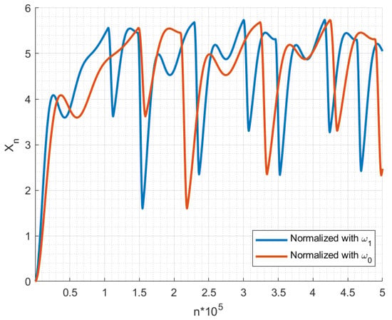
Figure A3.
Normalized time diagram of x state variable in the case of and normalizations in discrete time.
From the Figure A1, Figure A2 and Figure A3, it is apparent that the chaotic dynamic is preserved if the normalization frequency is changed. The attractors in the two cases match and the only difference is that the signals are stretched in time relative to each other, which is expected, knowing that changing normalization frequency only affects the time scale.
It is important to note that the end goal of such transformations in this case is implementing the discrete time model of the oscillator in a digital system (FPGA in this case) and matching the frequency of the digital oscillator to one of the analog oscillator. The digital oscillator has two time-related parameters that can be adjusted—the clock frequency and the time step . If the clock frequency is set, for digital chaos oscillator to match the analog oscillator, the time step must be the relation of the frequency of normalization to the clock frequency. In the case if the characteristic frequency is used, if the fundamental frequency is used to normalized equation, then (in this case the equation has the additional multiplication constant ). The relation of and is . It is apparent that whether normalization is performed using or for the digital implementation, the time step is selected with respect to the scaling frequency, thus the frequency of the digital oscillator matches the frequency of the analog oscillator.
References
- Vivek Menon, U.; Kumaravelu, V.B.; Vinoth Kumar, C.; Rammohan, A.; Chinnadurai, S.; Venkatesan, R.; Hai, H.; Selvaprabhu, P. AI-Powered IoT: A Survey on Integrating Artificial Intelligence with IoT for Enhanced Security, Efficiency, and Smart Applications. IEEE Access 2025, 13, 50296–50339. [Google Scholar] [CrossRef]
- Ahmed, S.F.; Alam, M.S.B.; Afrin, S.; Rafa, S.J.; Taher, S.B.; Kabir, M.; Muyeen, S.M.; Gandomi, A.H. Toward a Secure 5G-Enabled Internet of Things: A Survey on Requirements, Privacy, Security, Challenges, and Opportunities. IEEE Access 2024, 12, 13125–13145. [Google Scholar] [CrossRef]
- Gerodimos, A.; Maglaras, L.; Ferrag, M.A.; Ayres, N.; Kantzavelou, I. IoT: Communication protocols and security threats. Internet Things-Cyber-Phys. Syst. 2023, 3, 1–13. [Google Scholar] [CrossRef]
- Ullah, S.; Radzi, R.Z.; Yazdani, T.M.; Alshehri, A.; Khan, I. Types of Lightweight Cryptographies in Current Developments for Resource Constrained Machine Type Communication Devices: Challenges and Opportunities. IEEE Access 2022, 10, 35589–35604. [Google Scholar] [CrossRef]
- Migwi, D.; Romaniuk, R.S. Lightweight and Scalable Security for Wireless IoT Systems: Challenges and Research Directions. Int. J. Electron. Telecommun. 2025, 71, 1–8. [Google Scholar] [CrossRef]
- Babajans, R.; Cirjulina, D.; Capligins, F.; Kolosovs, D.; Grizans, J.; Litvinenko, A. Performance Analysis of Vilnius Chaos Oscillator-Based Digital Data Transmission Systems for IoT. Electronics 2023, 12, 709. [Google Scholar] [CrossRef]
- Petrzela, J. Chaos in Analog Electronic Circuits: Comprehensive Review, Solved Problems, Open Topics and Small Example. Mathematics 2022, 10, 4108. [Google Scholar] [CrossRef]
- Lau, F.C.M.; Tse, C.K. Chaos-Based Digital Communication Systems; Signals and Communication Technology; Springer: Berlin/Heidelberg, Germany, 2003; ISSN 1860-4862. [Google Scholar] [CrossRef]
- Kaddoum, G. Wireless Chaos-Based Communication Systems: A Comprehensive Survey. IEEE Access 2016, 4, 2621–2648. [Google Scholar] [CrossRef]
- Babkin, I.; Rybin, V.; Andreev, V.; Karimov, T.; Butusov, D. Coherent Chaotic Communication Using Generalized Runge–Kutta Method. Mathematics 2024, 12, 994. [Google Scholar] [CrossRef]
- Cirjulina, D.; Babajans, R.; Kolosovs, D. Design Particularities of Quadrature Chaos Shift Keying Communication System with Enhanced Noise Immunity for IoT Applications. Entropy 2025, 27, 296. [Google Scholar] [CrossRef]
- Ipatovs, A.; Victor, I.C.; Pikulins, D.; Tjukovs, S.; Litvinenko, A. Complete Bifurcation Analysis of the Vilnius Chaotic Oscillator. Electronics 2023, 12, 2861. [Google Scholar] [CrossRef]
- Cirjulina, D.; Tjukovs, S.; Babajans, R.; Bogdanovs, N.; Pikulins, D. Nonlinear Dynamics of the Colpitts Chaotic Oscillator Under Bias Voltage Tuning. In Proceedings of the 2025 IEEE 12th Workshop on Advances in Information, Electronic and Electrical Engineering (AIEEE), Vilnius, Lithuania, 15–17 May 2025; pp. 1–6. [Google Scholar]
- Zhang, X.; Li, C.; Huang, K.; Liu, Z.; Yang, Y. A Chaotic Oscillator with Three Independent Offset Boosters and Its Simplified Circuit Implementation. IEEE Trans. Circuits Syst. II Express Briefs 2024, 71, 51–55. [Google Scholar] [CrossRef]
- Chen, M.; Wang, A.; Wu, H.; Chen, B.; Xu, Q. DC-Offset Strategy for Controlling Hidden and Multistable Behaviors in Physical Circuits. IEEE Trans. Ind. Electron. 2024, 71, 9417–9425. [Google Scholar] [CrossRef]
- Kuznetsov, N.; Mokaev, T.; Ponomarenko, V.; Seleznev, E.; Stankevich, N.; Chua, L. Hidden attractors in Chua circuit: Mathematical theory meets physical experiments. Nonlinear Dyn. 2023, 111, 5859–5887. [Google Scholar] [CrossRef]
- Ramar, R.; Vaidyanathan, S. A New DC Offset Boostable Chaotic System with Multistability, Coexisting Attractors and Its Adaptive Synchronization. Sci. Iran. 2023; in press. [Google Scholar] [CrossRef]
- Pecora, L.M.; Carroll, T.L. Synchronization in chaotic systems. Phys. Rev. Lett. 1990, 64, 821–824. [Google Scholar] [CrossRef]
- Babajans, R.; Anstrangs, D.D.; Cirjulina, D.; Aboltins, A.; Litvinenko, A. Noise Immunity of Substitution Method – based Chaos Synchronization in Vilnius Oscillator. In Proceedings of the 2020 IEEE Microwave Theory and Techniques in Wireless Communications (MTTW), Riga, Latvia, 1–2 October 2020; Volume 1, pp. 237–242. [Google Scholar] [CrossRef]
- Boccaletti, S.; Kurths, J.; Osipov, G.; Valladares, D.L.; Zhou, C.S. The synchronization of chaotic systems. Phys. Rep. 2002, 366, 1–101. [Google Scholar] [CrossRef]
- Babajans, R.; Cirjulina, D.; Kolosovs, D. Field-Programmable Gate Array-Based Chaos Oscillator Implementation for Analog–Discrete and Discrete–Analog Chaotic Synchronization Applications. Entropy 2025, 27, 334. [Google Scholar] [CrossRef] [PubMed]
- Kennedy, M. Chaos in the Colpitts oscillator. IEEE Trans. Circuits Syst. Fundam. Theory Appl. 1994, 41, 771–774. [Google Scholar] [CrossRef]
- Cirjulina, D.; Babajans, R.; Kolosovs, D.; Litvinenko, A. Fundamental Frequency Impact on Colpitts Chaos Oscillator Dynamics. In Proceedings of the 2023 Workshop on Microwave Theory and Technology in Wireless Communications (MTTW), Riga, Latvia, 4–6 October 2023; pp. 19–23. [Google Scholar] [CrossRef]
- Li, C.; Jiang, Y.; Ma, X. On Offset Boosting in Chaotic System. Chaos Theory Appl. 2021, 3, 47–54. [Google Scholar] [CrossRef]
- Gottwald, G.A.; Melbourne, I. On the Implementation of the 0–1 Test for Chaos. Siam J. Appl. Dyn. Syst. 2009, 8, 129–145. [Google Scholar] [CrossRef]
- Saroja, G.; Nuriyah, L. Numerical Solution of Nonlinear Vibration by Euler-Cromer Method. Iop Conf. Ser. Mater. Sci. Eng. 2019, 546, 032029. [Google Scholar] [CrossRef]
- De Micco, L.; Larrondo, H.A. FPGA Implementation of a Chaotic Oscillator Using RK4 Method. In Proceedings of the 2011 VII Southern Conference on Programmable Logic (SPL), Córdoba, Argentina, 13–15 April 2011; IEEE: Piscataway, NJ, USA, 2011; pp. 185–190. [Google Scholar] [CrossRef]
- Tamaševičius, A.; Mykolaitis, G.; Pyragas, V.; Pyragas, K. A simple chaotic oscillator for educational purposes. Eur. J. Phys. 2004, 26, 61. [Google Scholar] [CrossRef]
- Namajunas, A.; Tamasevicius, A. Simple RC chaotic oscillator. Electron. Lett. 1996, 32, 945–946. [Google Scholar] [CrossRef]
- Noorizadegan, A.; Young, D.L.; Hon, Y.C.; Chen, C.S. Power-enhanced residual network for function approximation and physics-informed inverse problems. Appl. Math. Comput. 2024, 480, 128910. [Google Scholar] [CrossRef]
Disclaimer/Publisher’s Note: The statements, opinions and data contained in all publications are solely those of the individual author(s) and contributor(s) and not of MDPI and/or the editor(s). MDPI and/or the editor(s) disclaim responsibility for any injury to people or property resulting from any ideas, methods, instructions or products referred to in the content. |
© 2025 by the authors. Licensee MDPI, Basel, Switzerland. This article is an open access article distributed under the terms and conditions of the Creative Commons Attribution (CC BY) license (https://creativecommons.org/licenses/by/4.0/).