1. Introduction
The security and confidentiality of transmitted information have become critical priorities in today’s telecommunications environment, especially with the continuous growth of data exchange. As wireless technologies expand, the risk of attacks has also increased, necessitating the implementation of stronger mechanisms to prevent malicious interception or manipulation of signals [
1].
Modulation using chaotic signals has gained significant interest due to its unique properties, including unpredictability, low autocorrelation, and high sensitivity to initial conditions [
2,
3]. These characteristics not only enable greater spectral spreading but also provide enhanced protection for information confidentiality compared to traditional modulation schemes [
4,
5]. Chaos-based communication leverages the signal-masking phenomenon at the physical layer, which aids in the implementation of spread spectrum techniques [
6]. Additionally, chaotic signals possess an inherently broad spectrum, making them ideal candidates for applications in high-capacity communication [
7].
Different chaotic maps can generate multiple sequences with quasi-orthogonal properties by varying the initial conditions, significantly expanding the available coding space [
8,
9,
10]. In contrast, classical modulation techniques, such as quadrature amplitude modulation (n-QAM), although widely used, have certain drawbacks [
11]. For example, their energy efficiency is limited, which makes them more susceptible to decoding errors under challenging conditions like inter-symbol interference (ISI) or impulse noise [
12,
13]. Other methods that utilize conventional correlators with integrate-and-dump techniques have demonstrated improvements of up to eight dB in interference rejection and efficient synchronization in high-speed environments [
14]. These results provide a valuable framework for comparing potential extensions of our scheme, especially when evaluating performance in scenarios that more closely resemble RF hardware in multi-user settings.
Multiple access is essential in modern communication systems, as it plays a significant role in enhancing spectral efficiency, enabling user coexistence, and mitigating interference. Traditional techniques such as Frequency Division Multiple Access (FDMA), Time Division Multiple Access (TDMA), and Code Division Multiple Access (CDMA) have been crucial in the development of mobile networks. However, recent research has investigated the use of chaotic signals as a reference for creating more efficient multi-user schemes. This approach takes advantage of the properties of chaotic signals, including their ability to spread spectra and resist noise [
15,
16].
Among the most notable techniques is the Differential Chaos Shift Keying (DCSK) scheme, as introduced in [
17], which transmits a chaotic reference sequence followed by a replica modulated with the information. While this method allows for noncoherent detection and offers robustness to noise, it sacrifices spectral efficiency by dedicating half of the symbol duration to the reference signal.
In the literature, several variants of chaotic modulation have been proposed, such as CPSK (Chaos-based Phase Shift Keying), CSK (Chaos Shift Keying), QDCPSK (Quadrature Differential Chaos Phase Shift Keying), and QCSK (Quadrature Chaos Shift Keying), among others. These techniques seek to exploit the intrinsic properties of chaos, such as sensitivity to initial conditions and aperiodicity, with the aim of improving security, robustness, and spectral efficiency in digital communication environments. For example, [
18] describe the CSK technique, where each bit is represented by a chaotic signal or its inverse. Although this scheme improves spectral efficiency compared to DCSK, it requires strict synchronization, making it vulnerable to channel errors. In [
19], the CPSK technique encodes data in the phase of the chaotic signal; this approach improves transmission efficiency and rate, although it also demands precise phase synchronization. The QCSK [
20] and QDCPSK [
21] techniques carry these ideas into the quadrature domain to transmit bit pairs, increasing efficiency at the cost of greater complexity.
This research proposes the -CPSK–CSS–WCDMA modulation scheme, which integrates a Reconfigurable Chaotic Oscillator (RCO) as the core of the system. This oscillator allows the synthesis of differentiated chaotic symbols through dynamic parameter variation, generating multiple chaotic attractors. The application of the CPSK technique to this oscillator enables the creation of highly distinguishable waveforms, which are useful for encoding information with greater density and differentiation.
The integration of this modulation with the CSS (chaos-based selective symbol) technique allows for controlled synchronization between transmitter and receiver, enabling selective addressing of users. Each user can be identified by a unique chaotic pattern, which not only facilitates transmission multiplexing but also increases the physical security of the channel without the need for external cryptography. Because each symbol is composed of 24 chaotic signal segments generated by the RCO, the system can assign an independent segment to each user within the same channel, theoretically allowing a maximum of concurrent users. This capability provides a multi-user capacity that is significantly superior to that of classical schemes.
Furthermore, the W-CDMA technique, when used as a multiple access scheme, enables efficient assignment of chaotic codes to different users, taking advantage of the low autocorrelation and orthogonality of the generated sequences. This reduces inter-user interference and improves system scalability, making it suitable for high-spectral-density environments such as 5G and 6G networks or IoT systems.
To validate the practical feasibility of the proposed scheme, it was implemented on an Artix-7 FPGA platform in the 2.45 GHz ISM band, which is freely available and widely used in short- and medium-range wireless systems such as WLAN, Bluetooth, or sensing applications [
22]. This choice facilitates the future integration of the technique in real-world scenarios.
Additionally, this work is inspired by previous hybrid schemes such as those presented in [
23], where chaotic multiplexing strategies with cross-talk protection are explored. Regarding technical challenges, studies such as [
24] analyze the effects of perturbations on the stability of chaotic oscillators. Meanwhile, ref. [
25] delves into the numerical precision required to preserve state-space dynamics in digital implementations. Along the same lines, ref. [
26] presents an OFDM-based system with secure real-time transmission by combining chaotic symbols and QAM, achieving a key space on the order of
.
In contrast to previous techniques such as CSK, DCSK, QCSK, or QDCSK, which tend to focus solely on modulation or theoretical simulations, the hybrid architecture presented here enables a complete solution involving modulation, chaotic coding, multiple access, and synchronization. All of this is achieved through the combined use of OCR, CSS, and W-CDMA on a digital platform capable of operating in real time. The main contributions of this article are as follows:
- (i)
Design of a reconfigurable chaotic oscillator (RCO) capable of emulating classical 3D and 4D chaotic systems, enabling the generation of diverse waveform patterns suitable for communication schemes.
- (ii)
Proposal of a hybrid CPSK–CSS–WCDMA modulation scheme integrating the spreading gain of W-CDMA with the robustness of chaos-based parameter shift keying (CPSK) and the selective synchronization strategy of CSS.
- (iii)
A synchronization/desynchronization mechanism introducing a fast and adaptive chaos-based symbol-selective (CSS) approach that enables reliable symbol detection even under conditions of low autocorrelation.
- (iv)
Performance evaluation on the AWGN channel with analysis of critical metrics such as BER, ACPR, and PAPR, demonstrating that the proposed model ensures bandwidth efficiency, avoids adjacent channel interference, and mitigates voltage-spike variations in chaotic segments.
- (v)
Practical implementation considerations including validation of the scheme’s feasibility using FPGA platforms (Artix-7 AC701, Zedboard, and AD9361), highlighting its potential for real-time applications.
This article is organized as follows:
Section 2 presents the theoretical background, including the RCO model and the equations of the 12 chaotic oscillators used to generate reference signals for the
-CPSK–CSS–WCDMA technique.
Section 3 describes the system model of
-CPSK–CSS–WCDMA, the CSS-based encoding, the integration of the WCDMA technique, and the operation of the receiver for decoding the original information.
Section 4 details the digital development in VHDL, as well as the parameters and characteristics used in the hardware implementation and radio-frequency (RF) testing.
Section 5 presents the results and discussion of the performance analysis, including energy and spectral efficiency, error probability, PAPR, and ACPR; these were used to evaluate system behavior under transmission conditions. Finally,
Section 6 presents the conclusions.
3. System Model of the -CPSK–CSS–WCDMA Transceiver
In this article, a modulation scheme with an order of
is proposed as an initial approach to exploring the potential of chaotic systems for use in transmitting large volumes of information per symbol. This foundation provides a solid platform that can be extended in future works by incorporating variable-modulation schemes or higher levels that dynamically optimize system capacity and efficiency. The CSS scheme exploits the low correlation between fragments generated by different chaotic dynamics, enabling highly selective and secure encoding. In the proposed system, CSS generates a unique identifier for each user, as shown in Equation (
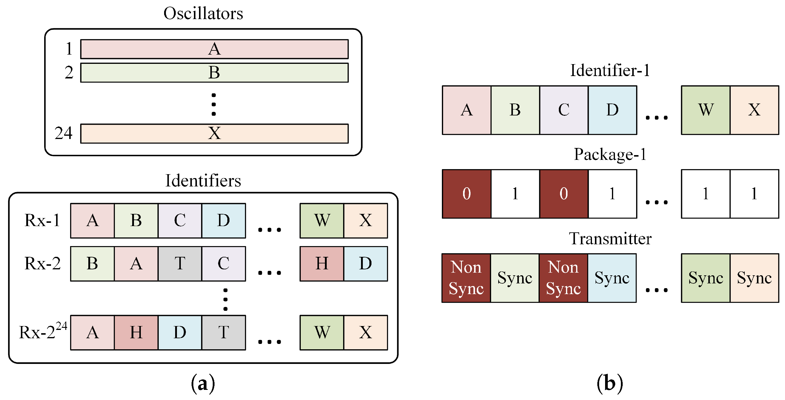
6). This identifier is composed of an ordered sequence of 24 segments of distinct chaotic signals.
where
represents the chaotic oscillator assigned to the
i-th segment of user
j and
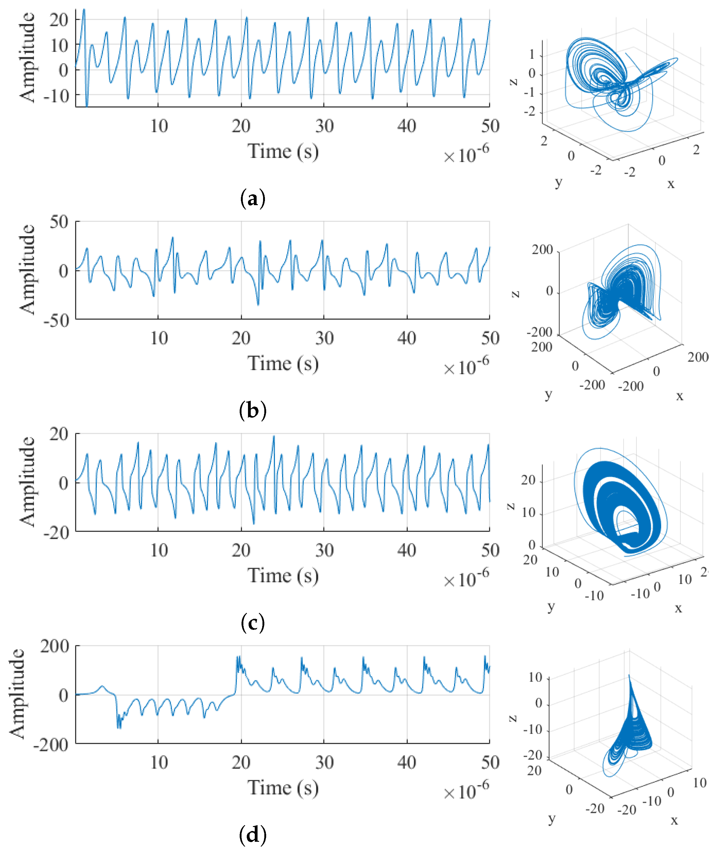
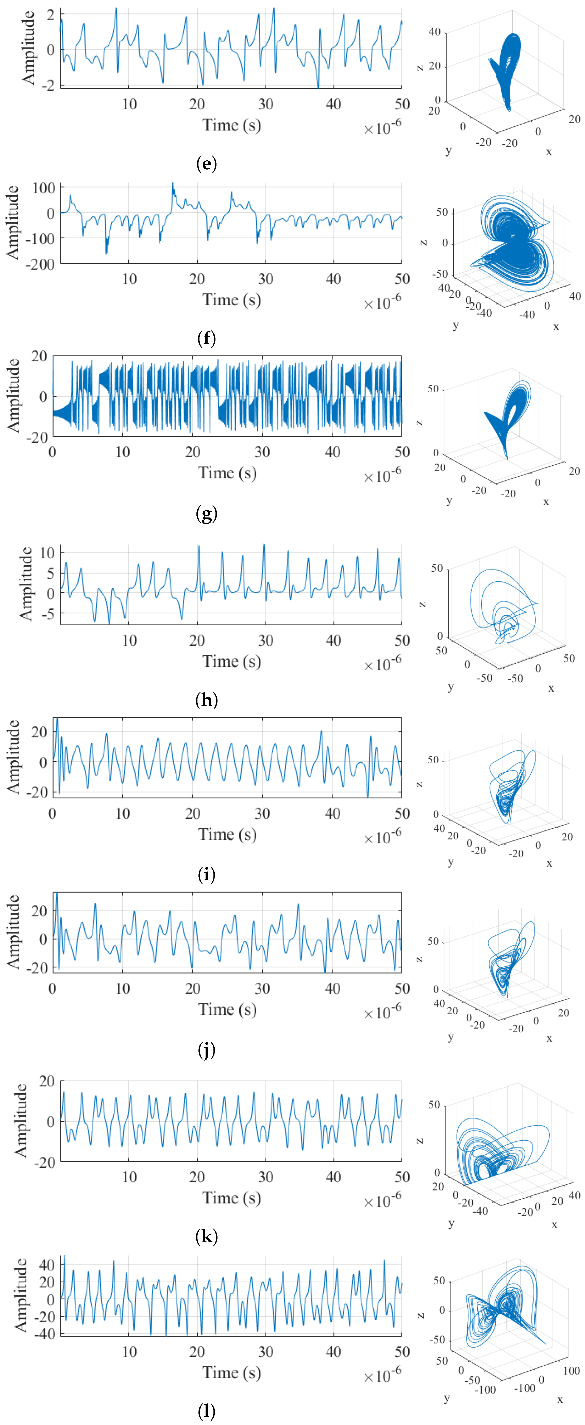
denotes the set of 12 chaotic oscillators presented in
Table 1. During transmission, the master system encodes a 24-bit binary message by dynamically selecting chaotic segments that either match or differ from the synchronization profile of the receiver. Let
be a 24-bit word representing the symbol to be transmitted for user
. For each bit
, the transmitted signal in the interval
is defined as shown in Equation (
7):
where
is the output of the oscillator corresponding to segment
i of user
j and
is the output of an oscillator different from that of user
j, selected to prevent synchronization. The total transmitted signal is presented in Equation (
8):
where
corresponds to the transmitted signal composed of 24 segments from different chaotic oscillators,
is the duration of each segment,
is the index of the segment within the chaotic symbol,
is the output of the
x variable from the
i-th RCO,
is the duration of each chaotic segment, and
corresponds to the user code in the W-CDMA technique.
Figure 2a illustrates how the 24 chaotic sequences are segmented to create user identifiers, while
Figure 2b shows the transmitter configuration required to send Package-1 using Identifier-1.
3.1. Synchronization
Synchronization is a key process for message recovery at the receiver. Since each message bit is represented by a segment of chaotic signal generated by a specific oscillator, synchronization enables the receiver to distinguish between high bits (+1) and low bits (–1) based on its ability to synchronize with the transmitter for each segment. Starting from the optimized RCO in Equation (
4), Equations (
9) and (
10) were developed and represent a chaotic transmitter oscillator
and receiver oscillator
, respectively.
where
is the vector field of the RCO (identical in both transmitter and receiver),
are the parameters of segment
i, and
is the coupling vector. For a given segment
i, if the receiver uses the synchronizable oscillator, the synchronization error converges to zero according to Equation (
11), indicating the presence of a logical bit +1.
On the other hand, if
is nonsynchronizable, the error remains bounded but does not converge, as described by Equation (
12), indicating the presence of a logical bit –1.
where
is the lower bound of the synchronization error when there is no match between transmitter and receiver and
T is the minimum time from which synchronization is evaluated. Based on the error, the receiver measures a synchronization index
during segment
i, as shown in Equation (
13):
Then, a binary decision function is applied according to Equation (
14):
where
is a synchronization threshold.
3.2. -CPSK–CSS–WCDMA Transmitter
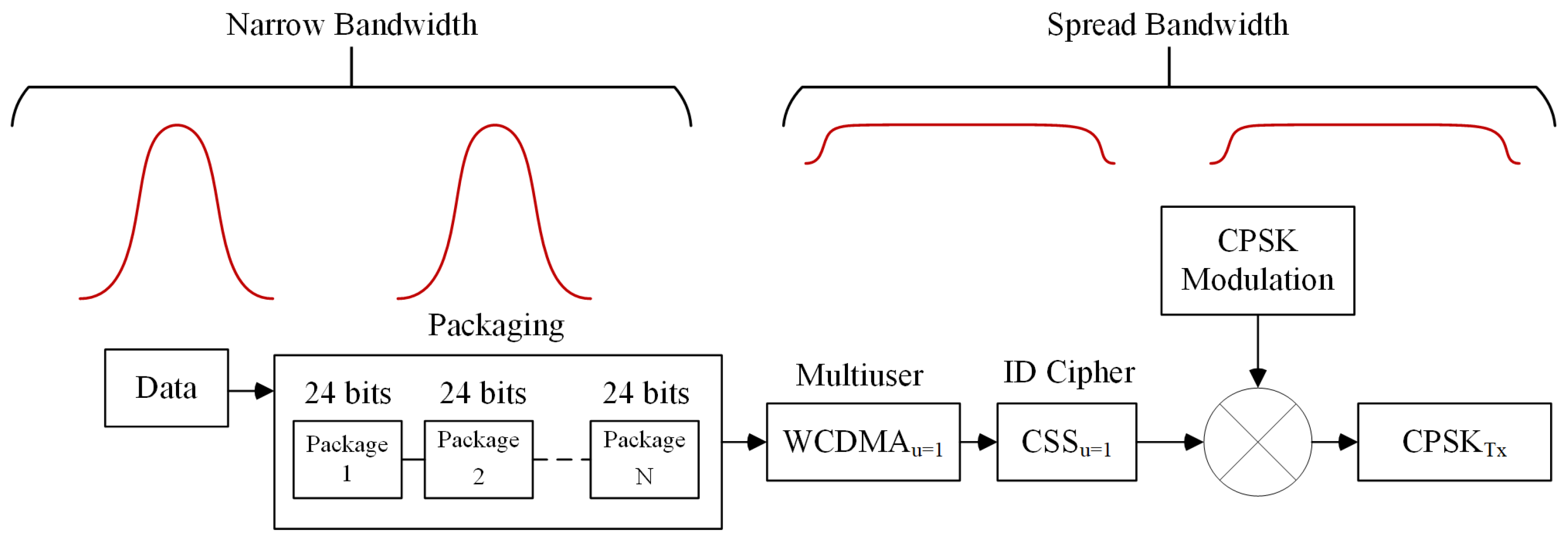
The information flow requires the packaging of data into 24-bit frames, multiuser WCDMA encoding, user-specific ID-based encodes, CPSK modulation, and transmission, as shown in
Figure 3. The WCDMA and CSS techniques have the particular feature of spreading the bandwidth of the information.
Figure 4 illustrates the structure of the transmitter for
-CPSK-WCDMA. In the initial stage, bits are packaged into clusters of 24. After this, parameters for the RCO are assigned based on the user identifier for the message being transmitted. Once the plot sequence has been generated by the RCO according to these parameters, the WCDMA multi-user communication technique is applied to facilitate the transmission.
3.3. Receiver -CPSK–CSS–WCDMA
The block diagram of the receiver structure for the
-CPSK–CSS–WCDMA technique is depicted in
Figure 5. In the demodulation process, the receiver focuses on synchronizing with each of the 24 segments of the received symbol using a dedicated set of slave chaotic oscillators for each segment. If synchronization occurs in a specific segment, the corresponding bit is interpreted as +1; if not, it is assigned a value of −1. Thus, the binary criterion for decoding each bit of the transmitted symbol relies on the status of synchronization between the received chaotic segment and its counterpart at the receiver. To manage data packaging and identify the receiver, the transmitter configures its identifier to match the receiver’s identifier in only those segments where the bit value is +1. This alignment enables synchronization of the chaotic segments. In contrast, for segments that correspond to a bit −1, the identifiers are designed to differ, thereby preventing synchronization. This dynamic is illustrated in
Figure 6, where segments that cannot be synchronized correspond to a bit −1.
4. Hardware Design
The
-CPSK–CSS–WCDMA technique was developed using the VHDL language in the Vivado 2020.2 environment. The system architecture is divided into two main sections: the transmitter and the receiver, which are composed of a total of six distinct modules. These modules are identified as follows: Identifier Generator, CPSK–CSS–WCDMA Modulator, Master Oscillator, Slave Oscillator, Error-Correction Module, and CPSK–CSS–WCDMA Demodulator, as illustrated in
Figure 7. The input signals for the complete system are
, corresponding to the FPGA card clock, and
, which represents the 24-bit message package. Master Oscillator: This module generates chaotic waveforms using a four-channel RCO at
,
,
, and
. It requires two inputs:
for synchronization and
to configure the oscillator being generated by the master system. Both the transmitter and receiver are set up to create and attach the 12 chaotic oscillators listed in
Table 1. Slave Oscillator: Each receiver employs a uniquely configured slave oscillator. This oscillator uses an RCO to generate waveforms based on the 12 chaotic oscillators from
Table 1 in a specific order, producing the channels
,
,
, and
. The slave oscillator synchronizes each received segment with a locally generated segment. The
,
,
, and
are error-correction signals utilized in the process of synchronization between the master and slave oscillators. Identifier Generator: This entity generates a user identifier in the master oscillator for a specific receiver, ensuring that a binary message can be encoded differently for each receiving user. The operation of this module requires
for synchronization and the
, a five-bit binary code that specifies how each message is encoded according to the receiver. CPSK–CSS–WCDMA Modulator: This module requires the
signals for synchronization,
for the 24-bit message,
as the receiving user identifier, and
to specify which chaotic oscillator will be used based on the user identifier. This ensures that for each user, there is a unique order in which their oscillators generate waveforms. CPSK–CSS–WCDMA Demodulator: Similarly to the modulator, this entity requires
signals for synchronization,
(which corresponds to the output of the 24-bit message), and
to inform the slave oscillator about the types of waveforms to be generated. Additionally,
indicates the similarity between the symbols generated by the receiver and those received from the transmitter. Error-Correction Module: This entity receives inputs from the transmitter
and outputs from the receiver
. It performs an error-correction process and generates
, which are the error-correction signals utilized by the slave oscillator.
Additionally, in
Table 2, the logical resources required by artix-7 AC701 (XC7A200TFBG676-2) are shown.
Hardware implementation was carried out as follows: the proposed communication system was synthesized on an FPGA with a maximum operating frequency of 200 MHz. The logical-resource utilization was moderate compared to the total capacity of the device, indicating an efficient use of programmable logic. Specifically, the system utilized 6400 of 134,600 LUTs (4.75%), 1239 of 269,200 registers (0.46%), 6 of 67,300 multiplexers (0.0089%), 300 of 740 DSP blocks (40.5%), 110 of 400 input/output pins (27.5%), and 2 of 32 buffers (6.25%). These results indicate that while the system makes extensive use of DSP blocks, consistent with the chaotic signal processing and synchronization requirements, most logical resources are underutilized, leaving significant capacity for future extensions, including the integration of additional coding techniques or adaptive modulation control.
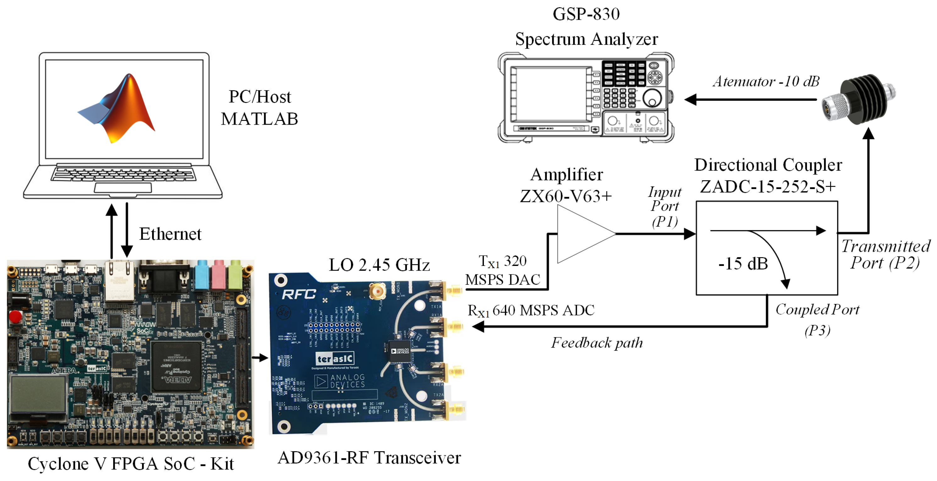
Figure 8 illustrates the experimental equipment used for the RF measurements. The setup includes an integrated Zedboard FPGA card paired with the Transceiver AD9361, responsible for the transmission and reception of modulated signals. For spectral analysis, a GSP-830 spectrum analyzer is employed, along with a ZADC-15-252-S+ model directional coupler that extracts a portion of the transmitted signal for monitoring without interfering with the main propagation. For experimental testing, a Mini-Circuits ZX60-V63+ broadband amplifier was used, operating in the 0.05 to 6 GHz range. This device offers a typical gain of approximately 20 dB, with a noise figure of around 3.6–3.8 dB at the frequencies of interest, and is designed for linear transmission applications in high-dynamic-range communication systems. This amplifier was selected because its 1 dB compression point (P1dB ≈ 18 dBm) and its third output intermodulation intercept (OIP3 ≈ 33–34 dBm) guarantee linear operation at the power levels used in this study, avoiding significant degradation of the modulated signal. Additionally, the transmission chain included a Mini-Circuits ZADC-15-252-S+ directional coupler with a typical insertion loss of 0.7 dB in the 850–2500 MHz range; this could be used for signal monitoring without significantly affecting the delivered power. Finally, a fixed 10 dB attenuator was incorporated to protect the system’s downstream stages and adjust the output power level to a safe and controlled range. Together, these losses (≈10.7 dB considering the coupler and attenuator) reduce the system’s effective output power but ensure stable and reproducible operating conditions under which to evaluate the
-CPSK–CSS–WCDMA signal, maintaining linearity and preventing adjacent channel encroachment. This combination of instruments enables the evaluation of spectral behavior and provides experimental validation of the proposed communication system’s performance.
On the other hand,
Figure 9 displays the measurement obtained from the spectrum analyzer GSP-830 for the modulated signal of
-CPSK–CSS–WCDMA. This measurement provides valuable insights into the spectral characteristics of the modulated signal, highlighting its performance in the communication system.
5. Results and Discussion
A relevant challenge in the implementation of an efficient synchronization system using a RCO is its propensity to synchronize multiple chaotic oscillators, even when they are inherently different. This can lead to significant challenges in bit detection. In
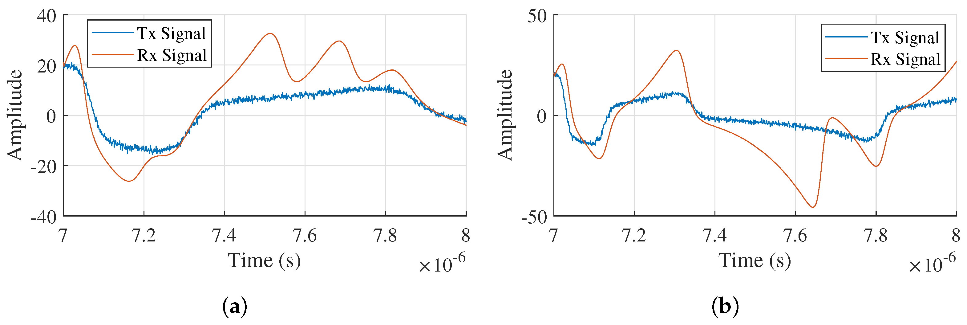
Figure 10, an arbitrary segment is presented in the range of 7–8 μs, corresponding to Master Oscillator No. 8 and Slave Oscillator No. 9, which transmits a bit −1. In this scenario, these segments are expected to be intrinsically nonsynchronizable. However,
Figure 10a illustrates an atypical case in which segments from different chaotic oscillators show a certain degree of synchronization, with a measured correlation of 92.45%. To address these spurious coincidences, the operating frequency of each oscillator was adjusted to introduce a slight difference between adjacent chaotic oscillators. This modification ensures effective decorrelation within the symbol period of 1 μs, thereby reducing the probability of spurious correlations.
Figure 10b depicts the same segments after a slight adjustment to the oscillator size parameter for No. 8; this resulted in a reduced correlation of 81.71%. This reduction is sufficient to accurately distinguish the state of the transmitted bit, effectively mitigating the risk of erroneous detection. Overall, these adjustments have proven essential in enhancing the reliability of the synchronization process, thereby improving the overall performance of the communication system.
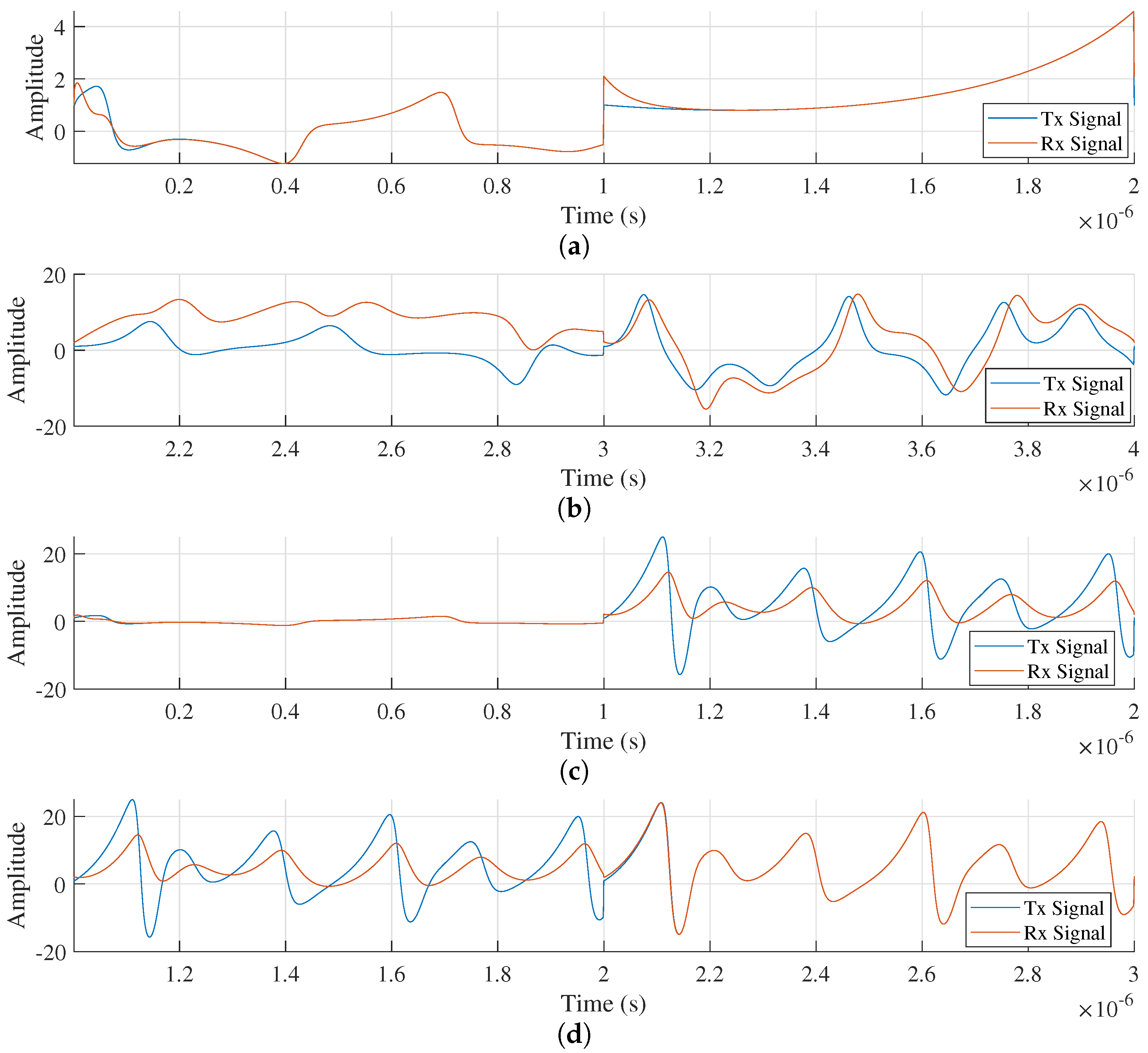
Similarly, four possible cases of interest in the synchronization and decorrelation process have been analyzed in this article:
Case 1 (
): When both symbols are positive, the system must preserve synchronization during the transition between chaotic signal segments, as depicted in
Figure 11a.
Case 2 (
): When both symbols are negative, the system needs to maintain decorrelation when moving from one chaotic signal segment to the next, as shown in
Figure 11b.
Case 3 (
): In this case, the system must remain synchronized during the first segment and then induce decorrelation in the second segment, as depicted in
Figure 11c.
Case 4 (
): In this case, the system must maintain decorrelation during the first segment and achieve synchronization in the subsequent segment, as illustrated in
Figure 11d.
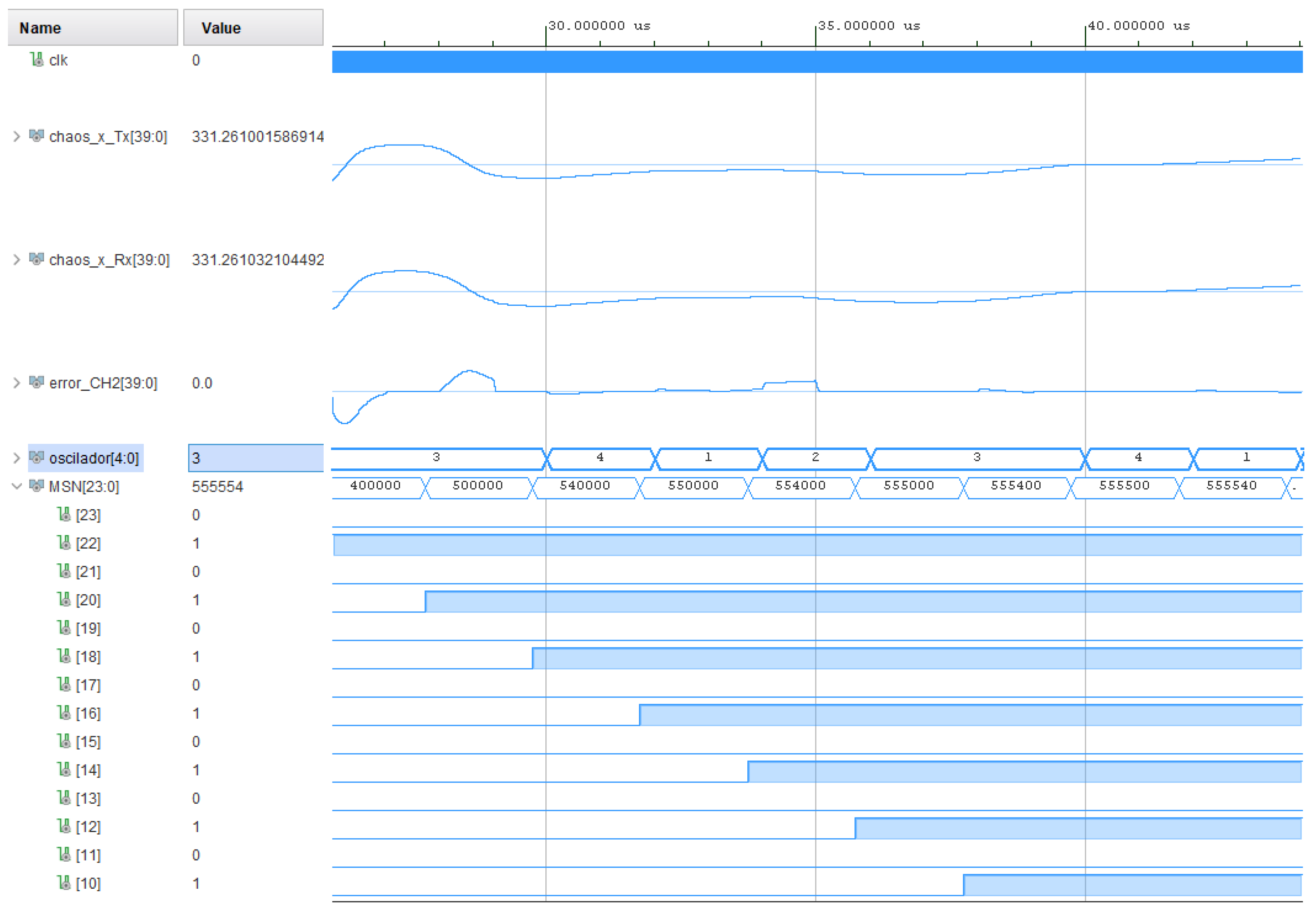
Figure 12 presents the simulation results obtained from the live software, showcasing a plot composed of “10101010…”. In this plot, the signals labeled
correspond to the transmitter channel, while
represents the receiver channel. The signal
displays the real-time error estimation between the transmitter and receiver and thus aids in the determination of the segment bit. Lastly,
illustrates the plot of recovered bits, demonstrating the effectiveness of the synchronization and decorrelation processes throughout the communication system.
On the other hand
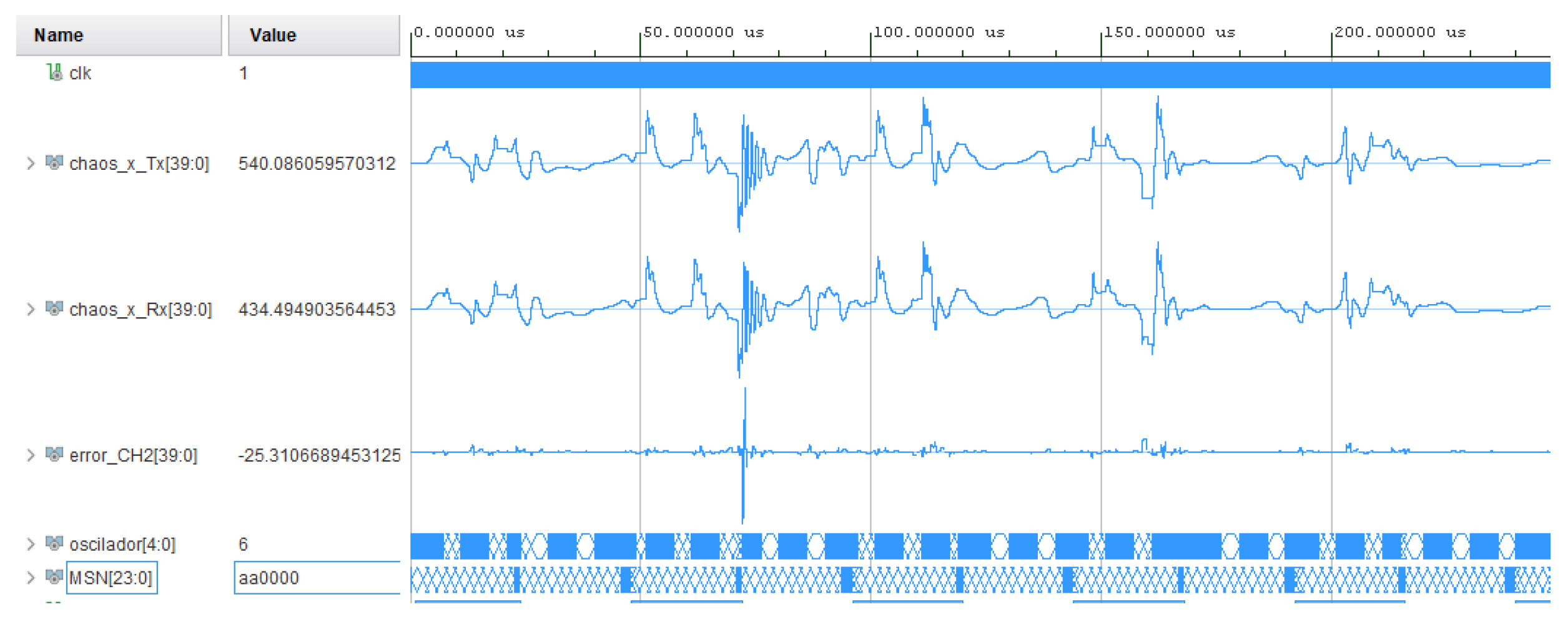
Figure 13 shows 200 transmission microseconds during which the plots received on the MSN signal can also be seen.
Since the system relies on the transmission of short-term chaotic segments (1 μs per segment) generated by the RCO, it is crucial to ensure that receivers can synchronize only with the segments corresponding to their unique user configurations. To facilitate this,
Table 3 presents the synchronization results obtained between the master and slave oscillators. In the proposed modulation scheme, synchronization between oscillators is strictly permitted only between equivalent pairs, such as Master
N with Slave
N for the transmission of a bit +1. Conversely, for the transmission of a bit −1, the pairings must involve nonequivalent oscillators, for instance, Master
N with Slave
, and these combinations are inherently nonsynchronized. However, due to the structural similarities between certain RCO configurations, it is not uncommon to observe high levels of synchronization among different oscillators. This phenomenon can create ambiguity during demodulation if proactive measures are not implemented. In this context, the oscillators have been arranged to ensure that the equivalent pairs highlighted in blue in
Table 3 are synchronizable, while the combinations of Master oscillators
N with Slave oscillators
highlighted in red are designated as nonsynchronizable. This delineation is critical for maintaining the integrity of the demodulation process and ensuring correct bit interpretation.
Table 3 gives the synchronization levels achieved through various combinations of the 12 oscillators listed in
Table 1. As shown, different oscillators exhibit varying levels of synchronization. However, this variability is not a concern, as the modulation scheme is specifically designed to be influenced only by the red and blue diagonals. The red diagonal includes the combinations used to transmit nonsynchronizable symbols, while the blue diagonal includes combinations that are synchronizable. This structured approach ensures that the system effectively manages synchronization, allowing for reliable bit transmission without interference from the high levels of synchronization observed in other oscillator pairings. This separation helps maintain the integrity of the modulation scheme, enhancing overall system performance.
5.1. Energy Efficiency
A fundamental metric for evaluating the energy performance of modulation schemes is the data-to-bit energy ratio (DBR), which quantifies the relationship between the total energy invested in transmitting a symbol and the average energy associated with each useful information bit. In the proposed
-CPSK–CSS–WCDMA scheme, each symbol is constructed by temporally concatenating
segments, with each segment generated by a distinct chaotic oscillator. Each symbol conveys
bits of information, assuming that all segments are utilized for the transmission of useful data. In this context, the total energy of the symbol
can be expressed using the following Equation (
15):
where
represents the energy of the
i-th chaotic segment. If we assume that all segments possess the same average energy
, then the total energy of the symbol
can be rewritten as follows in Equation (
16):
Since the symbol transports
b bits, energy per bit is defined as shown in Equation (
17).
Therefore, the DBR for the
-CPSK–CSS–WCDMA scheme is expressed in Equation (
18):
This result indicates that, under ideal conditions of maximum efficiency, the data-to-bit energy ratio (DBR) is equal to the number of bits transmitted per symbol. In
Table 4, the DBR models of various chaotic modulation schemes reported in the literature are compared to the proposed
-CPSK–CSS–WCDMA system.
5.2. Spectral Efficiency
The relationship between the bits rate and the total bandwidth is called spectral efficiency and is modeled from Equation (
19):
where
represents the bit rate in bits per second and
B denotes the bandwidth in Hertz. For the
-CPSK–CSS–WCDMA system, the bit rate can be calculated as
, where
μs is the duration of the symbol. This results in
Mbps. Furthermore, the low-sampling bandwidth according to Nyquist’s theorem is given by
, where
is the sampling frequency. In this case, we are using a
FPGA card, yielding
MHz. Thus, the spectral efficiency of the system can be expressed as
. In
Table 5, the models that represent the spectral efficiencies of different chaotic modulation schemes reported in the literature, including the technique proposed in this article, are shown.
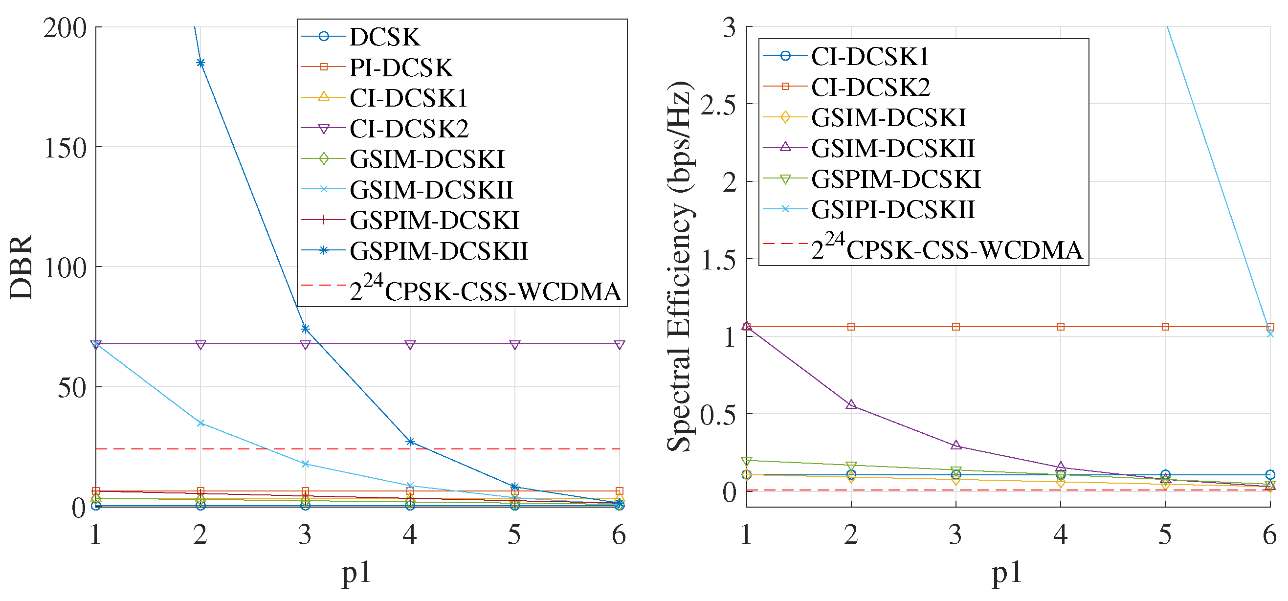
Figure 14a shows the DBR results of various techniques reported in the literature compared with the results of the
-CPSK–CSS–WCDMA technique proposed in this study. As can be observed, the DBR remains constant at a value of 24. This approach’s performance is surpassed by that of the CI-DCSK2 technique and under certain conditions by those of the GSPIM-DCSKII and GSIM-DCSKII techniques. The DBR metric is mainly used for techniques that transmit multiple bits per symbol or that use a symbol set to transmit a single bit, as in the case of the DCSK technique, where one segment serves as the reference and the other carries the information bit. In the case of the
-CPSK–CSS–WCDMA technique, a single symbol transmits 24 times more energy than each individual bit, resulting in a constant DBR value. On the other hand,
Figure 14b shows the plots of the spectral efficiency values from
Table 4, where the system proposed in this work maintains a constant value of 0.01.
In the proposed technique, the system’s spectral efficiency is intentionally low, as the technique employs highly spectrally spread chaotic signals along with redundant coding based on dynamic synchronization and multiuser access. Thus, the system is optimized not for minimal spectral occupancy, but rather for enhanced security and robustness against interference.
Figure 15 highlights a key property of the proposed scheme: its ability to increase the occupied bandwidth as the amount of transmitted information increases, from 1 frame up to 100 frames. This spectral spreading originates from the chaotic nature of the segments composing the signal and is further enhanced by the structural diversity introduced through the use of the RCO. By increasing the signal’s entropy and avoiding deterministic repetitions, the system achieves greater dispersion in the frequency domain. This not only makes detection more difficult but also improves the system’s robustness against interference and nonideal communication channels. This feature makes the
-CPSK scheme an attractive modulation technique for applications requiring confidentiality and resilience against passive eavesdropping.
5.3. Bit Error Probability Model Based on Correlation
Since the demodulation system implemented in this communication scheme is based on the correlation technique, the analysis of the bit error probability (
) can be formulated analogously to that of conventional systems, regardless of whether the signal used is sinusoidal or chaotic. In particular, the binary decision process relies on comparing the correlation value with a decision threshold
. When a binary bit
is transmitted and a chaotic signal
known to the receiver is used, the received signal in the presence of additive white Gaussian noise (AWGN) is expressed by Equation (
20).
where
is noise with power spectral density
. The decision is made by evaluating the correlation value according to Equation (
21).
The bit state is determined as
if
and as
if
. In this context, the bit error probability is modeled according to Equation (
22).
Here,
represents the energy per bit,
is the noise power spectral density, and
Q is a function defined by Equation (
23).
This model enables the analysis of the system’s sensitivity to variations in the threshold
, as well as the prediction of performance in terms of
versus the
ratio, even in the presence of chaotic signals.
Figure 16 shows the plot of
against
.
5.4. PAPR Model
A critical aspect of the design of chaotic communication systems is the relationship between the peak instantaneous power and the average power, known as the Peak-to-Average Power Ratio (PAPR), which is described by Equation (
24),
where
denotes the peak instantaneous power of the transmitted signal and
represents its average power over time. This metric quantifies the variability in the envelope of the transmitted signal and has a direct impact on power-amplifier efficiency, as a high PAPR requires operation with larger back-off margins to avoid nonlinear distortion. In the proposed CPSK-CSS scheme, which is based on the transmission of chaotic segments, the PAPR value is influenced by both the aperiodic dynamics of the oscillators and the number and combination of segments per symbol. The evaluation of PAPR, complemented by its statistical distribution using the Complementary Cumulative Distribution Function (CCDF) as described in Equation (
25), allows for the statistical characterization of the transmitted signal and helps anticipate its impact on the transmission chain [
40,
41],
where
is the probability that the PAPR exceeds its average value, denoted by
.
Figure 17 presents the PAPR analysis using CCDF curves for the proposed
-CPSK–CSS–WCDMA scheme. In
Figure 17a, the PAPR profiles obtained individually for 12 different chaotic oscillators are compared, revealing a wide performance range. In contrast,
Figure 17b shows the result after these oscillators have been combined within the RCO-based modulation process, yielding a signal with a significantly more controlled and uniform PAPR behavior. This behavior is mainly attributed to the emergent chaotic dynamics resulting from the simultaneous combination of the 12 oscillators, which introduces structured complexity in the time domain and reduces the likelihood of high-power peaks. The proposed system presents proven robustness through bit error rates (BER) lower than
for signal-to-noise ratios (SNR) greater than 20 dB, even in multi-user scenarios. Furthermore, improved spectral efficiency was observed, with a PAPR of 4.89 dB using a
and an ACPR of
dBc at an input power of
dBm. These results demonstrate a more efficient use of the spectrum and a more linear operation of the power amplifier.
PAPR analysis shows that both the chaotic reference oscillators and the full system maintain peak values below 5dB, indicating favorable energy performance. These results confirm that the proposed scheme offers a reliable, energy-efficient, and secure modulation strategy suitable for multiuser hardware-constrained environments.
Table 6 presents a comparison of the PAPR obtained using the proposed technique against the values obtained using state-of-the-art methods.
As shown in
Table 6, the proposed scheme achieves a PAPR value of
dB with a
, outperforming most of the compared methods. The exception is the SCHUR + WHT + CAZAC-OFDM scheme, which exhibits a lower PAPR of
dB; however, this advantage is associated with the use of a 16-QAM quadrature modulation, which handles 4 bits per symbol, in contrast to the 24 bits per symbol handled by the proposed system. This demonstrates that the
-CPSK–CSS–WCDMA scheme not only provides higher spectral efficiency, but also maintains a competitive PAPR, which is essential for linearity in RF transmitters.
5.5. ACPR Model
A fundamental metric for evaluating spectral efficiency and the interference generated by a communication system is the Adjacent Channel Power Ratio (ACPR) [
47]. This metric quantifies the level of unwanted energy that spreads outside the main transmission band into adjacent channels, which is particularly relevant in schemes employing aperiodic or wideband signals, such as the proposed chaotic system. ACPR is defined as the ratio, expressed in decibels, between the average power contained in an adjacent channel and the power in the main band, as shown in Equation (
25). More negative ACPR values indicate better spectral confinement of the signal, which reduces interference with other systems operating at nearby frequencies. In the context of the present modulation system based on segmented chaotic signals, ACPR evaluation enables the analysis of the impact of both the design of the chaotic oscillator and the spectral spreading behavior.
where
is the power measured in the adjacent channel and
is the power measured in the main channel. This ratio, expressed in dBc, indicates how much interference a signal generates in neighboring channels. A lower ACPR value implies better spectral performance and reduced interference.
Figure 18a shows the ACPR curves for the modulated signal over a power range from –28 dBm to –5 dBm, while
Figure 18b displays the frequency spectrum for a transmission using the
-CPSK–CSS–WCDMA scheme. In this work, the system was implemented in the 2.45 GHz band, using the frequency bands
GHz,
GHz,
GHz, and
GHz.
For the results shown in
Figure 18b, the output power was adjusted exclusively using the internal controls of the AD9361 transceiver, without the use of external power amplifiers. As a result, an atypical slope can be noticed in the ACPR curve. This can be attributed to the transceiver’s own limitations, particularly its dynamic range and noise floor level. The incorporation of an external amplifier in future work will allow for a more precise characterization of the system’s nonlinear behavior and a more representative evaluation of the ACPR under real transmission conditions. To extend the transmission range and evaluate adjacent channel leakage, the setup incorporated a Mini-Circuits ZX60-V63+ amplifier, which provides ≈ 20 dB gain, P1dB ≈ 18 dBm, and OIP3 ≈ 33–34 dBm, ensuring operation in a linear region with minimal distortion. Due to its high IP3 relative to P1 dB, the amplifier introduces considerably attenuated nonlinear distortion products under linear operating conditions. Consequently, the performance of the transmitted signal is primarily influenced by the system’s noise floor rather than by third-order distortion. This pattern aligns with the observed near 1 dB/dB slope in the ACPR, contrasting with the anticipated 2 dB/dB increase seen in a distortion-limited scenario. The
-CPSK–CSS–WCDMA system was implemented on the Artix-AC701 FPGA and demonstrated efficient use of resources despite its complexity, with only moderate demands on LUTs, registers, and DSPs. Synchronization tests revealed directional synchronization between chaotic oscillators, enabling potential applications in asymmetric coding. The system’s robust performance was validated by high synchronization for positive bits and low synchronization for negatives, as expected. In terms of energy efficiency, it consistently achieved a fixed DBR of 24, outperforming many existing chaotic schemes. Although its spectral efficiency was low by design, favoring robustness and security, the system scaled bandwidth dynamically with information load, enhancing noise immunity. A comparison between the proposed
-CPSK–CSS–WCDMA scheme and similar techniques reported as state-of-the-art approaches is presented in
Table 7.
On the other hand, to highlight the fundamental differences between the
-CPSK–CSS–WCDMA proposal and conventional QAM-based schemes,
Table 8 is provided. QAM systems, while widely adopted for their simplicity and efficiency under ideal conditions, encounter considerable challenges in scenarios involving multiple users, adverse channel conditions, and the security demands of the physical layer. Conversely, the proposal outlined in this work combines chaotic signals, parameter shift keying, and W-CDMA-based multiple access techniques, offering a novel approach to addressing these limitations.
In contrast to conventional methods, which often lack real hardware implementation, this proposal has been successfully validated on an FPGA platform, showcasing its practical viability. Regarding security, the CPSK-CSS technique enhances protection at the physical layer by utilizing reconfigurable chaotic sequences, a feature not present in the referenced QAM schemes. Despite employing chaotic modulation, it requires an approximate SNR of 18 dB to achieve a in an AWGN channel. This performance places it competitively alongside 8-HQAM and 16-QAM, which necessitate up to 22 dB and 27 dB, respectively, under more challenging channel conditions such as ETU or Xie–Beaulieu. While the proposed scheme exhibits lower spectral efficiency (0.01), this is attributed to the robust design and the multi-user capability supported by W-CDMA and CSS techniques, making direct comparisons with single-user schemes less meaningful. Additionally, the PAPR = 4.89 is maintained at a moderate level, which is lower than that of schemes like 64-QAM and 1024-QAM, thus enhancing transmission efficiency. This study concentrated on validating the proposed scheme in an AWGN channel. However, it is essential to acknowledge that real-world wireless communication scenarios involve challenges such as time offsets between the transmitter and receiver, as well as multipath interference, which can significantly affect system performance. Future implementations could tackle these issues by employing auto- and cross-correlation techniques to enhance synchronization and aid in multipath estimation, thereby increasing resilience against frequency-selective fading. The experimental platform utilized in this research, which consists of the ZedBoard FPGA paired with the Analog Devices AD9361 transceiver, possesses features conducive to investigating these scenarios in subsequent studies. Although these capabilities were not fully leveraged in the current work, their relevance in addressing channel fading, multipath environments, and asynchronous user scenarios is acknowledged. This presents a promising avenue for future research aimed at validating the proposed system under more realistic transmission conditions.
6. Conclusions
This work proposes an innovative high-density chaotic modulation scheme, denoted as -CPSK, complemented by a WCDMA mechanism and the CSS technique, which exploits the low correlation between fragments generated by different chaotic dynamics. This enables highly selective and secure encoding. The core of the system is the RCO, which emulates multiple nonlinear dynamical systems by modulating up to 36 independent parameters, allowing for user-specific configurations. One of the main advantages of the proposed system is its ability to encode 24 bits of information into a single 24-microsecond symbol composed of 24 independent chaotic segments. Each segment is governed by a distinct oscillator, introducing significant dynamic diversity into the transmitted signal. This diversity, combined with the chaotic synchronization technique used for demodulation, enables secure and efficient transmission without relying on conventional periodic structures or carrier waves. The integration of the CSS scheme adds an additional layer of signal addressing and coding, where each receiver is identified by a unique oscillator pattern. This allows dynamic selection of transmitted segments as either synchronizable or nonsynchronizable, depending on the binary message content. This mechanism ensures that each receiver can correctly decode only the signals intended for it, thereby enhancing both the confidentiality and selectivity of the system. Furthermore, the use of WCDMA after chaotic modulation allows multiple users to share the same channel while maintaining orthogonality through appropriate spreading sequences. This multiprotocol integration contributes to improving the scalability of the system without compromising spectral efficiency. Although the proposed system has been validated through simulations and experimental tests in the 2.45 GHz ISM band, its potential use in next-generation communication environments like 5G remains a consideration for the future. This outlook is supported by attributes such as the low autocorrelation of chaotic signals, the multiplexing capability of the CSS-WCDMA scheme, and the design’s multi-user support, which allows for possible combinations. However, it is important to note that a comprehensive validation within 5G contexts will necessitate large-scale simulations in densely populated networks, along with testing under real-world channel conditions that account for latency, mobility, and intercellular interference. Therefore, this potential for scalability is proposed as an avenue for future research, rather than a definitive conclusion of the current study. The results indicate that, under the experimental conditions examined, the ACPR performance is influenced primarily by system noise, rather than by distortion from the amplifier. This outcome can be attributed to the operation of the ZX60-V63+ below its compression point and within its highly linear region, where the nonlinear effects on adjacent channels are minimal. As a result, the -CPSK–CSS–WCDMA signal preserves its spectral integrity without interfering with adjacent channels, thus fulfilling the linearity requirements necessary for wideband transmission. Overall, the proposed system represents a promising solution for secure, resilient, and spectrally efficient communication applications, especially in scenarios where robustness against noisy channels, interception attacks, or synchronization constraints is critical. Future work could focus on performance analysis over more complex fading channels such as Rayleigh or Rician channels, as well as on advanced error-correction schemes.
