1. Introduction
Physical experimental research on electron cyclotron resonance heating in Tokamak experimental devices and the commercial application of fusion energy are gradually improving the expected megawatt-level performance of gyrotrons [
1,
2,
3,
4,
5,
6,
7,
8,
9]. The International Thermonuclear Experimental Reactor (ITER) and China Fusion Engineering Test Reactor (CFETR), both in progress, have put forward the application requirements for high-frequency megawatt-level gyrotrons. A 170 GHz gyrotron has been under development at the Beijing Vacuum Electronic Research Institute (BVERI) for several years.
In 2017, the first version of a 170 GHz gyrotron was designed in BVERI, which employed the TE
25,10 as the operating mode. Its operating voltage was 80 kV and the current was 40 A, while the operating magnetic field intensity was 6.72 T. The theoretical calculation of the output power of the high-frequency cavity was about 1.1 MW (without considering the effect of velocity scattering). The transmission system, including the mode converter and window, had an efficiency of about 96%. The 170 GHz verification sample tube of the TE
25,10 mode output was completed in 2021. The power of this gyrotron achieved 200 kW at the 61 kV, 30 A operating point, and 300 kW at the 75 kV, 40 A operating point [
10].
On the basis of the 2021 research, contributing to the components of ceramic optimized, the resistance of the cathode and anode was increased to withstand 80 kV accelerating voltage. In 2022, a Gaussian quasi-optics mode transformation was employed to transverse the output mode from the TE25,10 to the Gaussian beam, and a single depressed collector was designed and applied to the upgraded gyrotron. In addition, in the process of designing MIG, it was necessary to pay close attention to matching of electric and magnetic fields, as well as the electrode deformation under the thermal field, since the cathode operates at high temperature. In this paper, the electric field (E-field), the magnetic field (M-field) and the thermal field(T-field) are comprehensively considered to analyze the influence of thermal field on the beam performance of MIG.
2. Design of MIG Without Thermal Field
To generate high-power microwave energy at high frequency, gyrotrons employ a resonator that couples the cyclotron electron beam and high-order mode to convert the electron kinetic energy into microwave energy. As shown in
Figure 1, the cyclotron electron beam (black circle) is designed at the peak of the E-field (red area) to maximize the interaction efficiency. Simultaneously, the interaction needs three parameters, namely guidance center radius, pitch factor, and velocity spread, to satisfy the requirements.
We designed a triode MIG to provide a cyclotron electron beam for a 170 GHz gyrotron. As shown in
Figure 2, the MIG had a gun region, transition region, and drifting region.
In the gun region, the emitter potential was identical for the rear electrode and front electrode, and the potential difference between the cathode and modulating anode caused a strong E-field to exist on the cathode surface. The E-field on the cathode surface was exactly perpendicular to the emitter and could be decomposed into and by refined optimization, resulting in the velocity of electrons emitted from the cathode being decomposed into and .
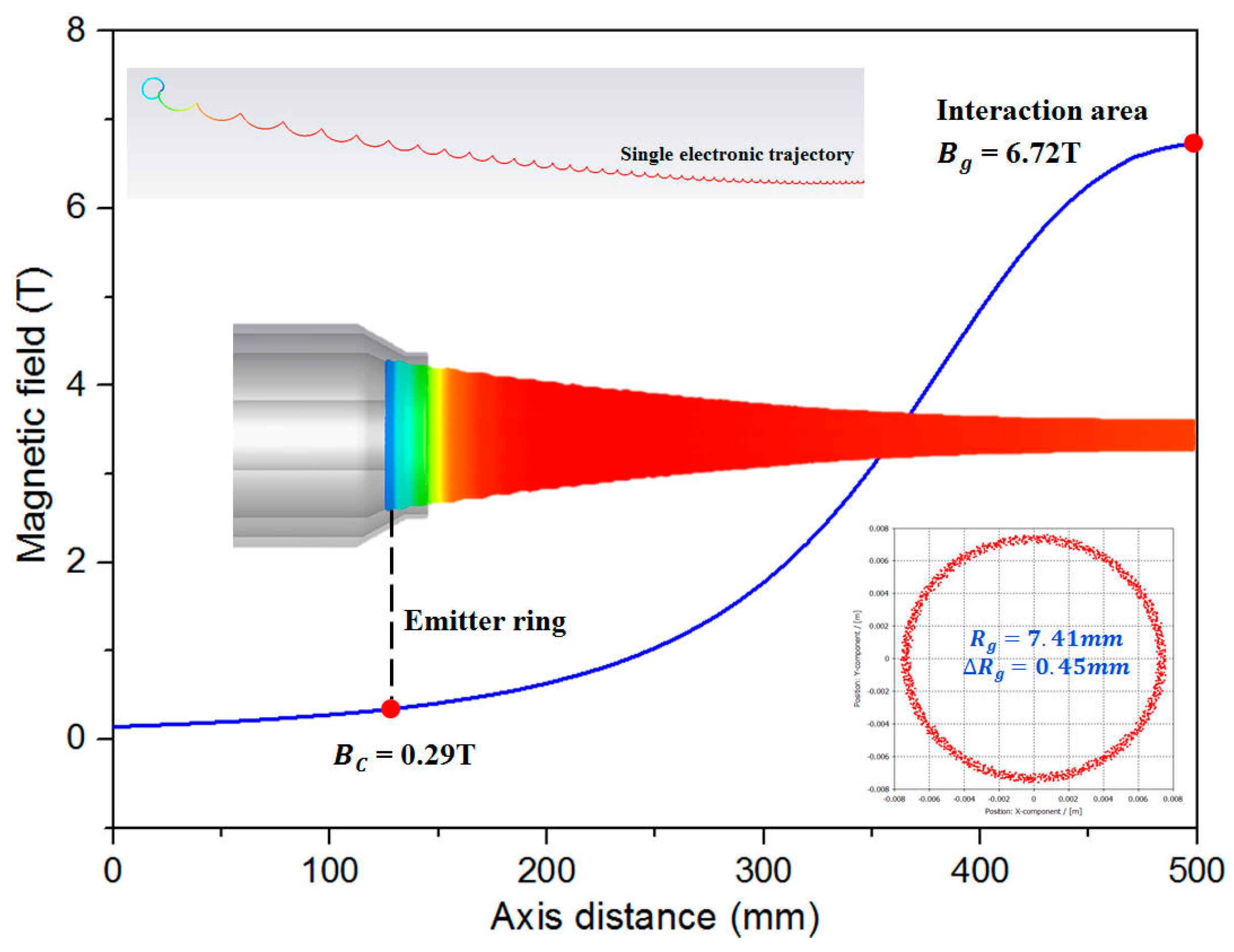
To guide the electrons following the desired trajectory, it was necessary to arrange the gradually varied M-field in the axial direction in these three regions ). In the transition region, the electron cyclotron frequency increases with the M-field, and the electron transverse velocity increases under the adiabatic compression effect.
As the E-field approaches zero, an equipotential space forms in the drifting region. Along the M-field field line, the intensity of the M-field increases and the change rate of the M-field decreases as the M-field at the exit of the MIG approaches a constant maximum value, in which the helical velocity reaches the designed maximum and the guiding center radius tends to be stable. The formula of the M-field compression ratio can be expressed as
It is convenient to calculate the correlation between the guiding center radius of electron and the M-field intensity along the axial, where and are the M-field intensity and guiding center radius at the position of resonator, and and are the M-field intensity and guiding center radius at the position of the emitter. Therefore, according to the guiding center radius of the electron beam in the interaction resonator and the M-field distribution of superconducting magnet, the radius of emitter can be determined.
The essence of the interaction between the electron beam and the microwave is to convert the angular (transverse) kinetic energy of electron into RF microwave energy. It should be noted that the transverse kinetic energy will be much greater than the longitudinal energy if the employed M-field is stronger than the matched E-field; therefore, the emitted electron may be trapped by the magnetic mirror in the reverse direction and accelerated by the E-field in the forward direction. The trapped electron increases the ionization probability, and the ionized particles [
11]. The pitch factor is defined to estimate the ratio of average transverse velocity
to average longitudinal velocity
as follows:
The transverse velocity of the electron at the interaction region
can be estimated as follows [
12,
13]:
Here, is the relativistic factor and is the electron emitted angle, which depends on the cathode angle. and are the E-field and M-field at the cathode, respectively. So and the match between the E-field and the M-field are the significant factors for the pitch factor under the determined accelerating voltage and operating magnetic field intensity.
Transverse velocity spread
and longitudinal velocity spread
can be estimated as follows:
There are three types of influencing factors of velocity spread in the experiment, which involves E-field and M-field mismatch
, surface roughness
, and thermal emission spread
, and where the total transverse spread
can be estimated as follows [
14]:
In the above formula,
is mostly affected by the surface roughness of the cathode, and
is mostly affected by the cathode material and its operating temperature. This paper focuses on the velocity spread caused by the matching E-field and M-field. In general, the magnetic line of force is perpendicular to the electric field line on the cathode surface, which benefits from the increase in the initial uniformity of the electron beam emitted from cathode. By optimizing the above, a triode–anode MIG was designed, for which parameters are shown in
Table 1. Under 80 kV of accelerating voltage, 45 A of operating current, and 6.72 T of interacting magnetic field for the fundamental 170 GHz/ TE
25,10 mode gyrotron, the simulated average pitch factor was 1.27, which satisfied the interaction requirement, while the transverse velocity spread was 2.72% and the longitudinal velocity spread was 4.87%. As shown in
Figure 3, the M-field of the emitter ring
was 0.29 T and the
. At the interaction area, the guiding center of beam
was 7.41 mm and the thickness of the beam
was 0.45 mm.
3. Analysis of MIG with Thermal Field
Under operating conditions, a high temperature was distributed in the electrode since the gyrotron employed a thermal cathode operating at approximately 1000 °C normally [
15], therefore it was critical to analyze the thermal field of the operating MIG and control the effect of electrode thermal deformation. A thermal experiment of MIG was designed to observe the temperature distribution in different areas of the MIG and obtain the correlation coefficient of the filament power and electrode temperature. By using the design scheme of the triode–anode MIG for a 170 GHz gyrotron described in
Section 2, a MIG component containing a modulation anode was fabricated, and employed a quartz disk window welding at the MIG output to maintain component at a low vacuum leakage rate, combining with an ion pump to maintain the vacuum degree at better than
Pa, to ensure a normal operating state of the filament and identical operating state with the gyrotron.
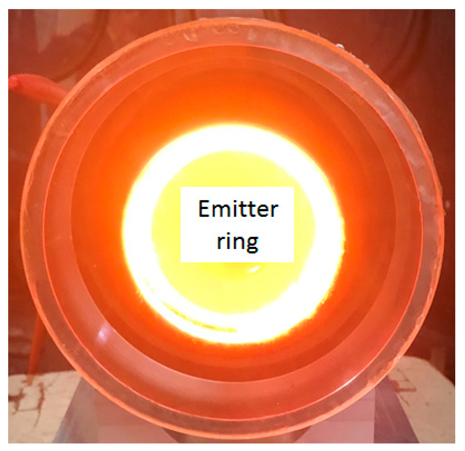
The temperature of the cathode, front electrode, and rear electrode were accurately measured from a quartz disk window by an infrared camera. As shown in
Figure 4, the color of the cathode surface was bright yellow under high operating temperature conditions, and an orange color could be observed at the surface of the front electrode and rear electrode, which had a lower temperature.
In the experiment, we changed the filament power in the range of 90 W–450 W by adjusting the filament supply voltage and current, and observed and recorded corresponding electrode temperature data shown in
Table 2.
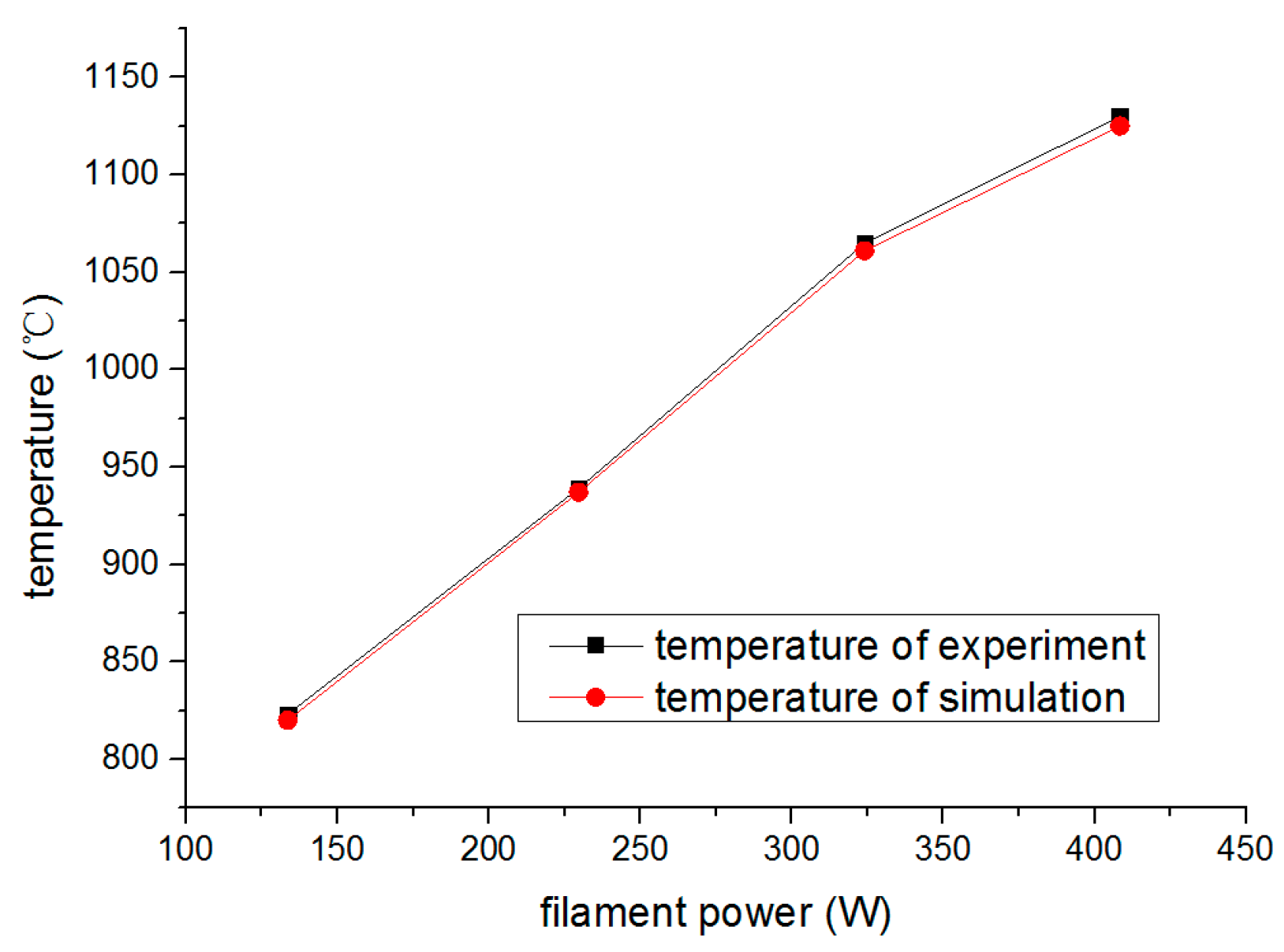
Based on the cathode thermal experiment, a calculation model was built and simulated using Annsys 16.1 software, with filament power set as the input parameter, to monitor the temperature of electrode as the judgment of calculation accuracy. To uniformize calculation and experiment results, the thermal emissivity coefficients and thermal conduction coefficients between various materials were modified. Typically, the thermal emissivity of molybdenum electrode was set to 0.15 at 600 °C and the surface of the cathode was set to 0.16 at approximately 930 °C; thus, reliable geometry deformation variables with measured temperature distribution under MIG operating conditions were obtained. The correlation of the relationship between the cathode surface temperature and heater power are shown in
Figure 5, which describes the temperature of the simulation comparable with the experiment.
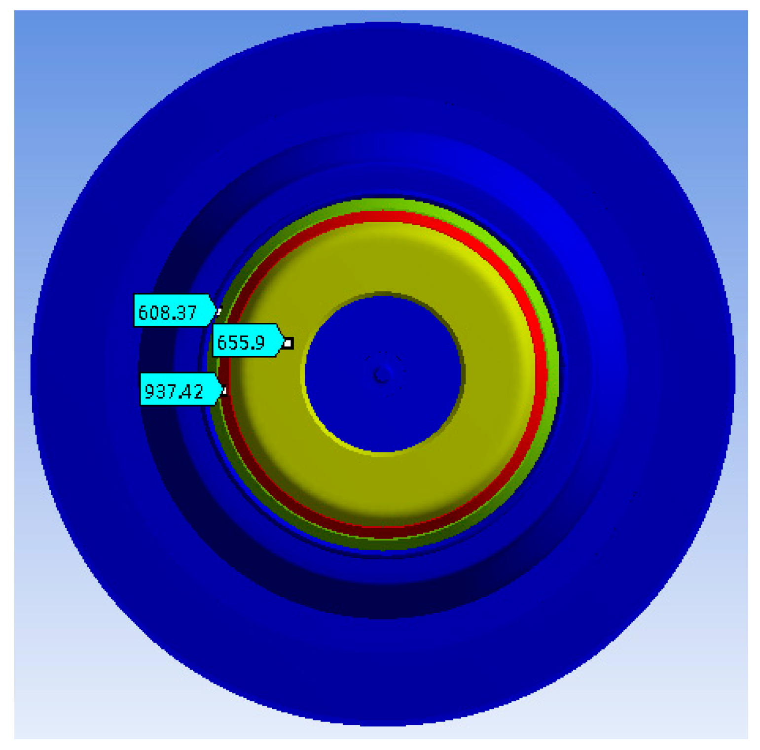
Figure 6 displays the temperature distribution of the MIG front view under a filament power of 220 W, where the temperature of the cathode surface is 937 °C (red ring). Because we employed a structure with superior thermal insulation capability, the temperature of the adjoining electrode showed obvious distinction, while the temperature of the front electrode was 655.9 °C and the temperature of the rear electrode was 608 °C. In practice, electron emission may cause the cathode surface temperature to decrease by approximately 3 °C per A/cm
2 of emission current density, meaning the cathode surface temperature in the operating gyrotron will be approximately 12 °C lower than the simulated value. This gap was ignored in the thermal deformation simulation as it is a subtle effect.
Based on the above model and results, the electrode geometric deformation of a 170 GHz gyrotron MIG under the described operating conditions was simulated. The power of the gyrotron filament was set at 220 W while the accelerating voltage was 80 kV and the operating current was 40 A in the experiment; three electrode geometric deformations are shown in
Figure 7. Under the influence of the thermal field, the cathode radius increased by 0.19 mm, equivalent to 0.53% of the original geometric dimensions, and the radial expansion dimensions of the front electrode and rear electrode were 0.11 mm and 0.12 mm due to their lower temperature under the operating state. At the same time, because the MIG component was welded to the tube body, these three electrodes expanded approximately 0.548 mm in the axial direction towards the cavity. The temperature of the modulating anode rose less than 10 °C and the geometric deformation caused by the thermal field was less than 0.01 mm. The simulated values of the electrodes’ deformation are listed in
Table 3.
4. Experimental Research
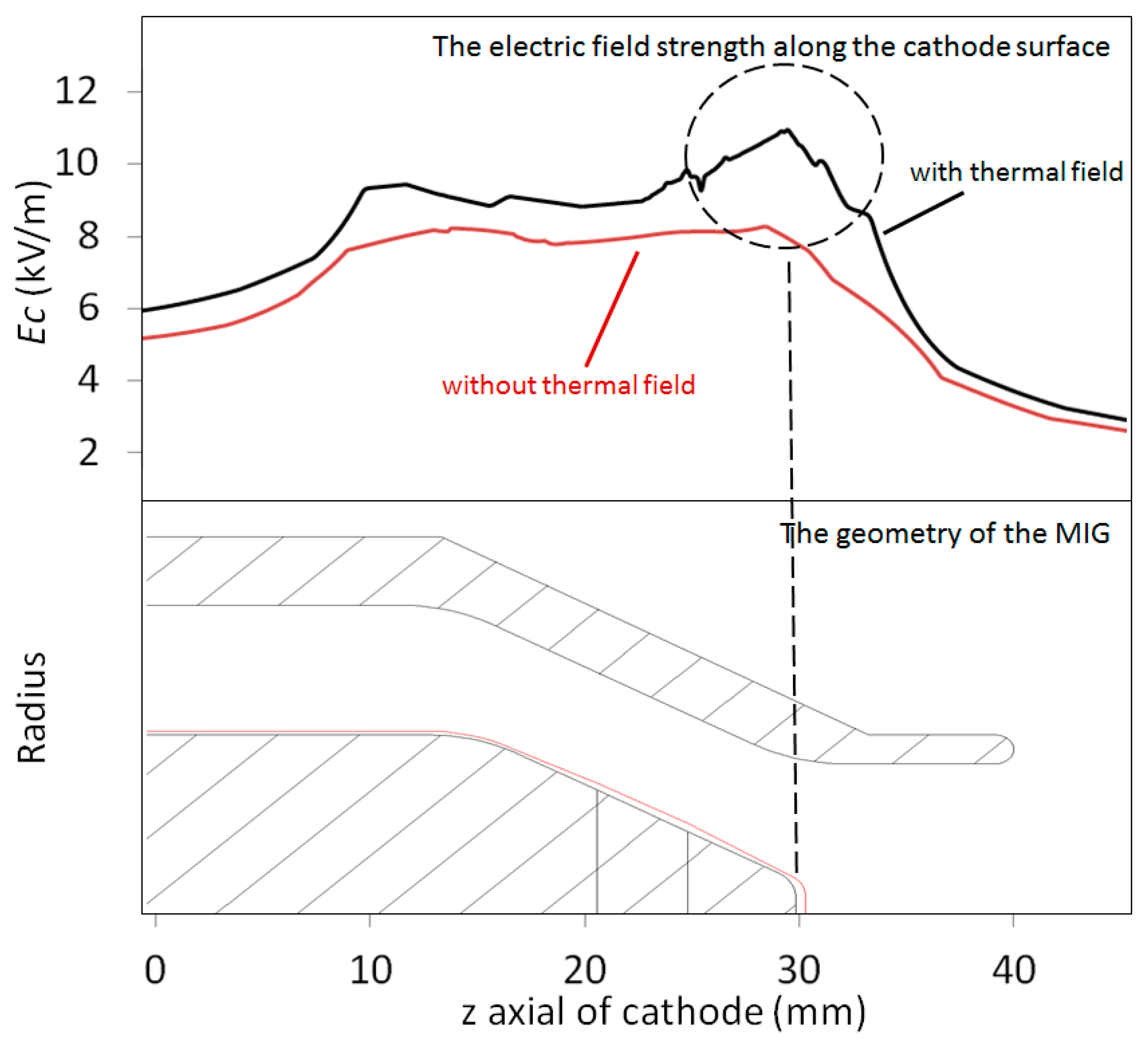
To analyze the effect of thermal deformation caused by the thermal field on the electron beam characters of a MIG for a 170 GHz gyrotron, the deformation of electrodes simulated in
Section 3 were corrected in the initial design model, and the MIG models with/without thermal field are shown in
Figure 8. The peak electrode field strength along the cathode surface increased from 8.0 × 10
6 V/m to 1.09 × 10
7 V/m, because the distance between the cathode and anode was reduced in the operating state. The red line in
Figure 8, which represents the operating state, spiked at the front electrode, and the compatibility between the E-field and the M-field in the cathode region was seriously damaged, which may cause an increase of initial electronic velocity, with the emitted angle changing and velocity consistency reducing. The main parameters comparing the electron beam performance with and without the thermal field are shown in
Table 4. Under the operating conditions, pitch factor increased by approximately 25%, and the transverse velocity spread and perpendicular velocity spread were more than doubled, exceeding the design baseline of 5%, which had a significant effect on beam–wave interaction.
To eliminate the influence of geometric deformation on the performance of the electron beam under the thermal field, practicability must be considered. Therefore, an optimized scheme of a triode–anode MIG was designed. The E-field distribution between the cathode and anode was adjusted by changing the configuration of three anodes, while decreasing the voltage of the modulating anode to suppress the peak E-field of the front electrode. The E-field and M-field of the cathode surface were analyzed and are shown in
Figure 9, in which the abscissa is the cathode position along the z-axis, the blue curve represents the E-field intensity on the cathode surface, and the red one represents the M-field strength at the axis of the MIG. At the emitter area, where the longitudinal length was 5 mm, the gradient of the E-field
and the gradient of the M-field
, an electromagnetic field match was perfectly achieved.
The optimized MIG, which considered both electromagnetic and thermal fields, is shown in the
Table 4. The results indicate that the pitch factor was reduced from 1.59 to 1.29, the transverse velocity spread was reduced from 5.91% to 3.27%, and the longitudinal velocity spread was reduced from 17.06% to 5. 82%, close to the initial simulation results of the MIG without the thermal field.
Using the initial MIG design scheme, Gyrotron-II was fabricated in 2022, with 80 kV of accelerating voltage, 40 A of operating current, and a 6.72 T magnetic field, and a Gaussian microwave beam was measured which achieved 10% efficiency at a frequency of 169.3 GHz. Based on the modified structure which eliminated the influence of geometric deformation with the thermal field, Gyrotron-III was fabricated in 2023 and achieved 19.7% efficiency under the same operating conditions, nearly doubling the beam-wave interaction efficiency.


