1. Introduction
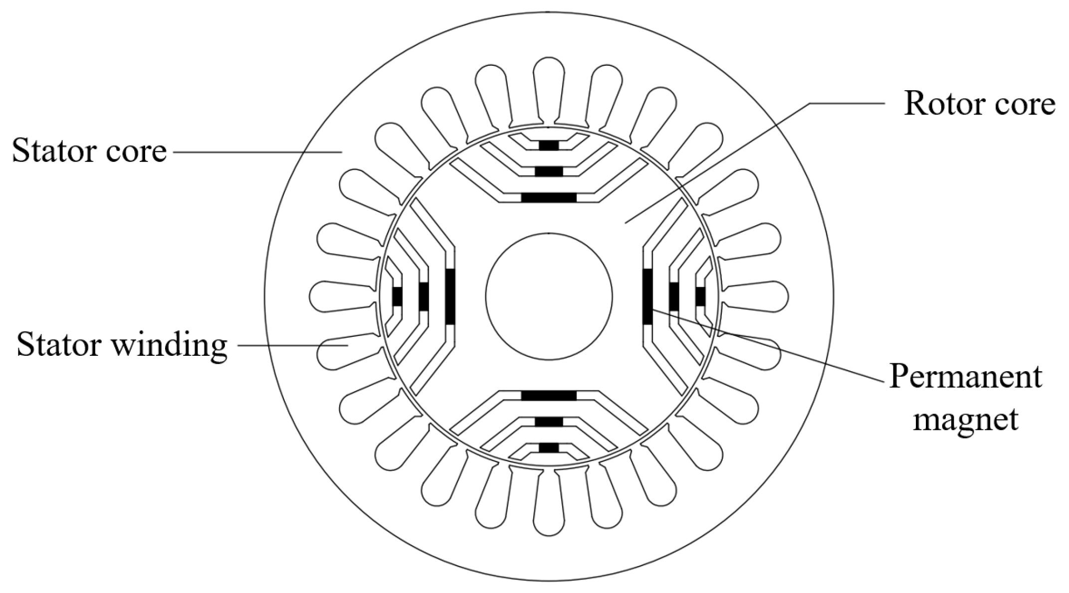
With the continuous deepening of research on permanent magnet (PM) materials, especially the emergence of high-performance NdFeB PM, the development of permanent magnet synchronous motors (PMSMs) has made significant breakthroughs. At present, most PMSMs use rare-earth iron boron PM, resulting in a large use of rare-earth PM. In order to reduce the dependence on rare-earth resources, reduce the damage to the environment, and the cost of the motor, it is urgent to develop a high efficiency motor with low rare-earth content or even no rare-earth. Permanent Magnet assisted Synchronous Reluctance Motor (PMaSynRM) combines the advantages of PMSM and Synchronous Reluctance Motor (SynRM), which efficiently integrates the reluctance torque and permanent magnet torque. It shows high power density and lightweight structure characteristics.
The key to the accurate control of PMaSynRM is to obtain the rotor position and running speed information in real time. However, traditional methods that rely on mechanical position sensors can no longer support the efficient improvement of motor performance under certain operating conditions. Compared with traditional control methods, “plug and play” sensorless control is more popular [
1]. At present, sensorless control methods are mainly divided into salient pole tracking based methods and fundamental frequency model based methods. The fundamental frequency model methods are mainly divided into back electromotive force (EMF) method and flux linkage method. The back EMF method is widely used to estimate the rotor position by observing the back EMF [
2]. Since PMaSynRM has a large salient pole ratio, the back EMF method needs to re-establish the model to realize the transformation from the salient pole motor to the equivalent hidden pole motor, and the process is relatively complicated. Compared with the back EMF method, the flux linkage method has received more attention because of it does not depend on the motor speed [
3,
4].
The flux linkage method consists of two models: the voltage model (VM) and the current model (CM). In order to apply flux observer based sensorless control method to salient pole motors, Koonlaboon S firstly applied the “virtual permanent magnet flux” model to the design of built-in PMSMs, so as to convert the salient pole PMSMs into easily processed hidden pole PMSMs [
5]. Thus, the concept of “active flux” is becoming increasingly mature in the current development [
6,
7]. However, the uncertainty of the motor parameters and the inaccuracy of the initial value of the integrator often lead to the DC drift of the output of the pure integration link [
8,
9], which not only directly affects the accurate measurement of the sensorless position, but also poses a challenge to the stable operation of the system. Further research on eliminating the DC bias of the flux can be found in [
8,
10,
11,
12]. The average value of flux is calculated in each cycle and the average value is subtracted from the obtained flux value [
8]. Although this method can eliminate the DC bias of the flux, it requires a lot of calculation and has poor dynamic response performance. The pure integral element is replaced by a first-order Low-Pass Filter (LPF) to filter out the DC bias component [
10,
11,
12]. However, when the motor speed is not high enough, the phase delay caused by the LPF will be significant, which will affect the position observation accuracy and system stability. In addition to the VM, the CM can also be used to estimate the flux, which uses the current and flux relationship of the motor to estimate the flux. However, the CM is more likely to be affected by inductance characteristics and PM parameters.
In view of the above problems, the method of closed-loop flux observer is derived. The closed-loop flux observer is a unique model reference adaptive system, which uses a proportional integral (PI) controller to fine-tune two independent but open-loop models, namely the voltage model and the current model. Gemma et al. in [
13], constructs a full-order flux observer based on the linear flux model to observe the active flux. However, this method assumes constant active flux amplitude, and the observation accuracy is reduced in the transient state. Holtz et al. in [
8], proposes a simple and effective closed-loop flux observer to solve the DC bias problem of voltage integral flux observer, and is applied to sensorless control of induction motor. This method requires constant stator flux and cannot be directly applied to PMaSynRM. In this regard, Li et al. in [
9], proposes an improved closed-loop flux observer for synchronous reluctance motors, which replaces the constant flux amplitude with the effective flux amplitude calculated online. H. Kim et al. in [
14], proposed an adaptive observer to extract fundamental waves in flux error, and analyzed the switching process between VM and CM. The CM played a leading role at low speed, and the VM played a leading role at high speed. In essence, the above flux observer method takes the active flux output of the current model as a reference, compares it with the signal output of the voltage model, and input the difference into the PI controller, and then uses the output of the PI controller to compensate the error caused by the integral DC bias and stator resistance change [
4,
15,
16].
In this paper, in order to optimize and improve the performance of motor control system, a sensorless control method of PMaSynRM based on active flux observer of VM and CM hybrid model is proposed. The definition of active flux is determined based on the mathematical model of the motor, and then an active flux observer is constructed, which includes VM and CM, in which a PI controller is added, and the CM is used as feedback to realize the correction of the stator flux and compensation of the back EMF. Then, the rotor position is estimated by observing the active flux. Finally, the simulations were carried out to verify the proposed method. The sensorless control method of PMaSynRM based on active flux observer of VM and CM hybrid model proposed in this paper has the following features:
The mathematical model of the PMaSynRM is constructed according to the basic structure and working principle of the motor, and then the active flux linkage of the PMaSynRM is defined after derivation. Compared with PMSM, PMaSynRM is unique in that it mainly uses reluctance torque rather than permanent magnet torque to drive. Compared with SynRM, PMaSynRM introduces PM to generate permanent magnet torque in traditional rotor designs. Therefore, the definition and control of active flux are different.
The proposed flux observer takes the stator flux and the angle observed by the VM as the input of the CM, and the current model outputs the estimated stator current after calculation. The stator current error is adjusted by PI and fed back to the voltage model to complete the closed-loop control. At the same time, the angle observed by the observer is used in the current model to achieve more complete closed-loop feedback.
The proposed flux observer can realize the stable operation of the PMaSynRM under sensorless conditions, achieve sensorless control in a wide speed range, and have high position observation accuracy, which can effectively improve the system’s load capacity and anti-interference ability.
The rest of this article is organized as follows.
Section 2, the working principle of PMaSynRM is summarized, and its mathematical model is constructed, based on which the active flux is defined.
Section 3, the advantages and disadvantages of VM and CM are compared, and the closed-loop control strategy combining VM and CM is adopted to construct an active flux observer.
Section 4 is simulation analysis and verification. The discussion and conclusions are included in
Section 5.
3. Active Flux Observer Based on Hybrid Model of VM and CM
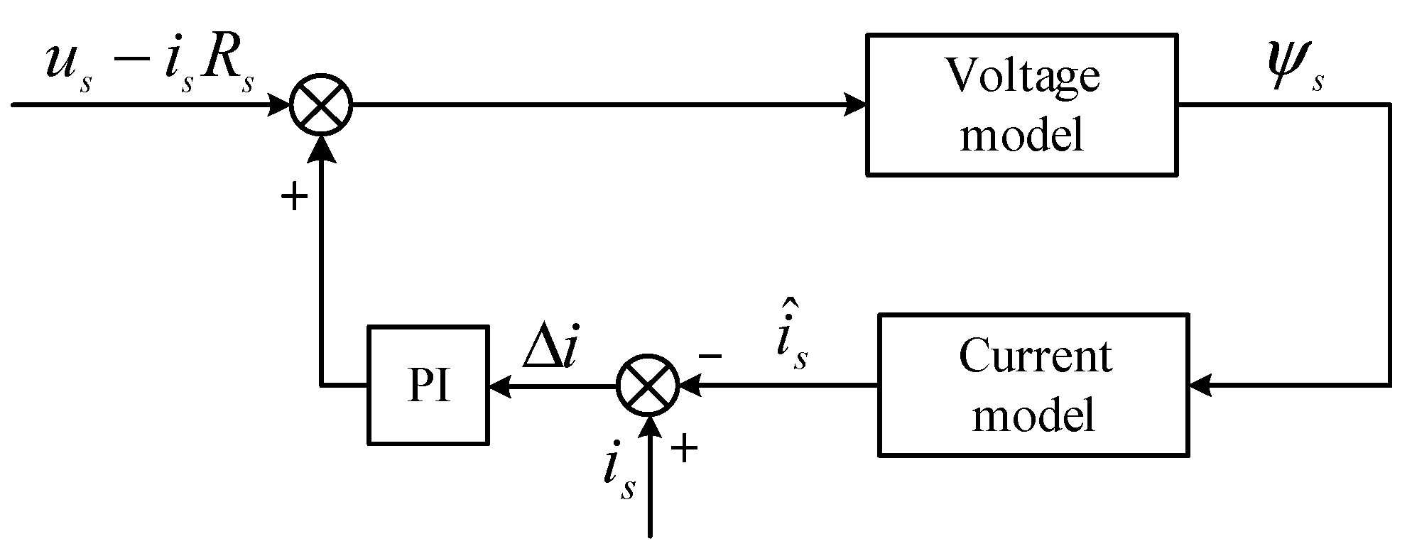
3.1. Traditional VM
The VM is widely used in the design of flux observer, and its typical structure is shown in
Figure 3.
In order to obtain an accurate active flux, it can be seen from (7) that the stator flux must first be accurately calculated, which can be achieved by integrating the back EMF. In the α-β coordinate system, assuming that the initial condition of the pure integral link is zero, the stator flux component of PMaSynRM can be calculated by the following formula:
Using the definition of active flux and the expression of stator flux, the active flux vector can be calculated according to the stator flux output from the VM as follows:
Under ideal conditions, the voltage and current signals obtained by sampling are standard sine waves and contain no harmonic and DC components. By integrating the fundamental frequency component of the back EMF with an ideal integrator, the fundamental frequency component of the flux chain can be accurately obtained without saturation.
In the practical application of motor control system, the problem of limited sensor accuracy and nonlinear sampling circuit is often encountered, which inevitably introduces DC bias in voltage and current. At the same time, due to the uncertainty of initial conditions, the integrator saturation phenomenon is often caused by pure integration, which undoubtedly affects the observable performance of the system.
When the input contains DC, fundamental frequency and higher harmonic components of the back EMF, the back EMF can be expressed as:
where the amplitudes of the DC component, the fundamental wave and the k-harmonics are denoted by
E0,
E1 and
Ek, respectively.
Laplace transformation of (11) is given as:
The stator flux is obtained by integrating it:
Inverse Laplace transformation of (13) is given as:
In (14), under the action of a pure integral link, the response characteristic of the back EMF will produce a ramp signal with increasing time and constant bias , which may lead to saturation of the flux, thus reducing the observation accuracy of the system.
3.2. Traditional CM
The CM can be constructed using coordinate transformation and flux linkage formula. In the CM, the estimated position information is used to participate in real-time calculation and is not affected by stator resistance, so the observation accuracy is higher at low speed.
In the d-q axis coordinate system, the stator flux linkage expression of PMaSynRM is as follows:
Apply the iPark transformation to (15):
As shown in
Figure 4 the CM, the first to Park transformation of stator current. Then get d-q axis using flux formula to compute flux. Finally, by iPark transformation, to obtain the accurate of the stator flux signal. In the conversion process between Park and iPark, the estimated angle is used, and the key is to rely on accurate angular velocity estimation to ensure high accuracy of flux observation even at low rotational speeds. Compared with VM, CM is more susceptible to the significant influence of inductance characteristics and permanent magnet parameters during processing, and its robustness is relatively weak. In addition, the model often involves coordinate transformations, and although common problems such as DC saturation are avoided, its convergence analysis is an important consideration.
3.3. The Proposed Hybrid Model of VM and CM
In order to display the advantages of VM and CM, they are combined and connected together through PI controller. The CM is used to correct VM to form closed-loop control, thus optimizing the overall performance of the control system.
In the VM, the flux linkage is often obtained by integrating the voltage. However, due to the uncertainty of the initial value of the integrator, the pure integral part is easy to cause DC migration, so it is usually necessary to consider the feedback compensation mechanism in the observer.
In this paper, the proposed model join the PI controller. The CM as a feedback, achieve to the stator flux linkage correction and the back EMF compensation. After the calculation through the CM, there is an error between the observed and the actual current. This error is processed by the PI controller, and then the back EMF is adjusted to achieve the precise calibration of the flux linkage.
During operation, the error caused by the VM is corrected by the CM, and the limitation of over-dependence on the specific parameters of the motor can be avoided when using the CM, because the CM is not directly used for angle determination in this process, thus increasing the flexibility and robustness of the system. The VM and CM hybrid model can not only significantly improve the accuracy of position observation, but also effectively avoid the conversion problem between models. To sum up,
Figure 5 shows the hybrid model of VM and CM used in this paper to observe the active flux, which improves the observation accuracy and optimizes the performance of the control system.
3.4. Active Flux Observer Based on Hybrid Model of VM and CM
In this paper, an active flux observer based on a hybrid model of VM and CM is adopted, and its detailed structure block diagram is shown in
Figure 6.
In this paper, the active flux observer uses a hybrid model of VM and CM.
First, the stator flux is obtained by voltage model and Formula (9), and the active flux is obtained by Formula (10). Then the observed angle and rotational speed are obtained by the arctangent method.
Secondly, The design strategy of the CM is to take the stator flux and the observed angle calculated by the VM as the input. First, the input stator flux Ψsα and Ψsβ are transformed by Park to obtain the d- and q-axis flux. Then, the d- and q-axis current is calculated by using the flux Formula (15) of the current model. Finally, the estimated stator current of the α- and β-axis is obtained by using the iPark transformation of the d-q axis current with the Formula (16). In the above process, the angle values observed by the observer are used in the Park transform and iPark transform of the current model.
Finally, the error of the stator current input PI regulator, the output feedback into the input signal voltage model, thus achieving a complete closed-loop control effect. It is worth noting that in the PI calculation, it is usually only necessary to select the proportional operation.
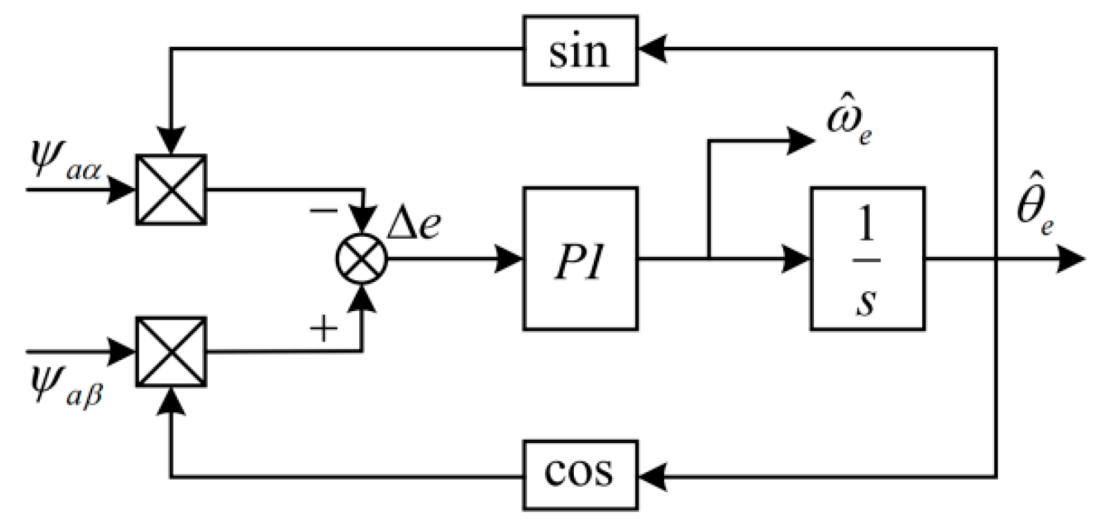
In addition, in practical engineering applications, inverse tangent and differential operations are often affected by various noises. Therefore, this paper uses the design of Phase Locked Loop (PLL) to estimate the angle and rotor speed, and its structure is shown in
Figure 7.
The principle analysis is as follows:
where
is the control deviation of the phase-locked loop and
is the rotor position error value; The control deviation
of PLL is close to 0, and the observed angular velocity
is obtained by PI control.
4. Simulation Verification and Result Analysis
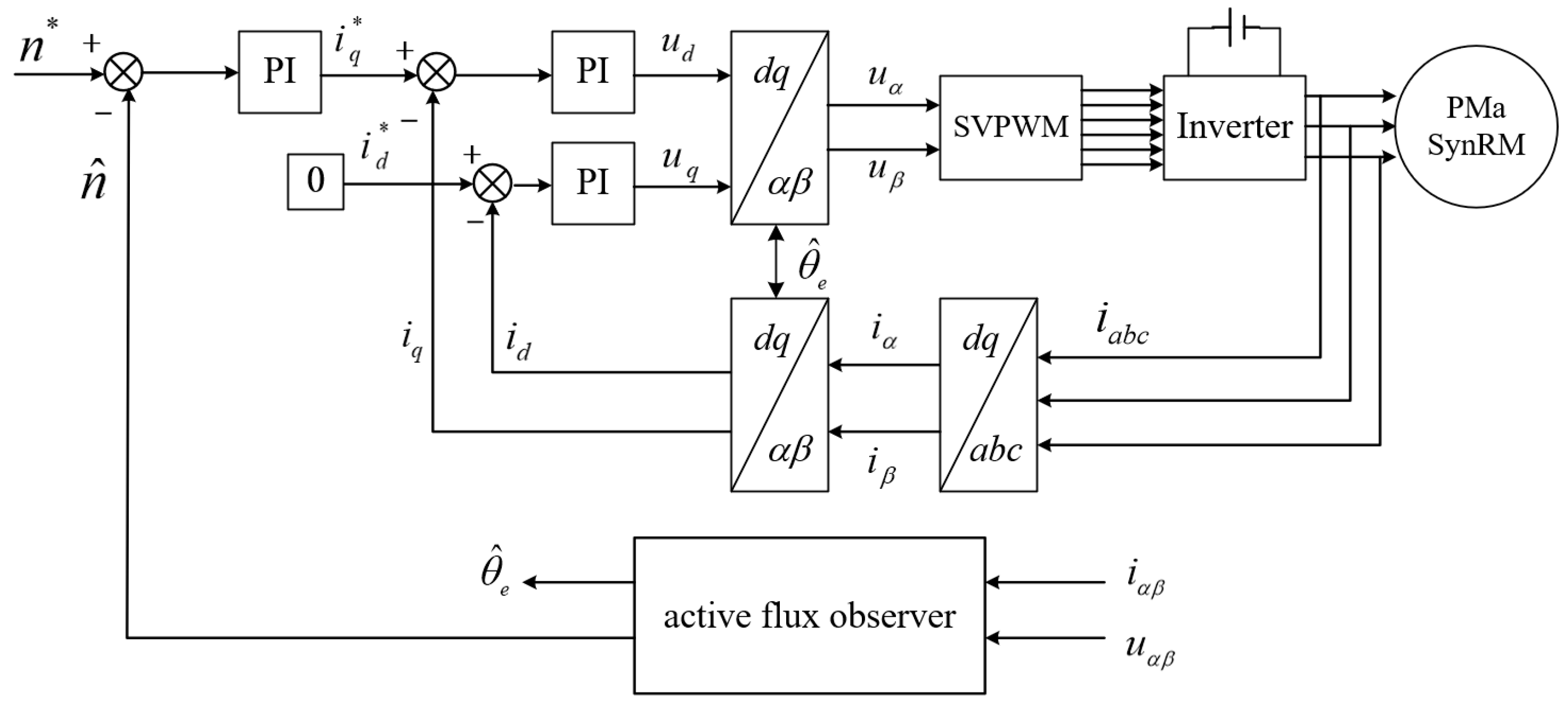
As shown in
Figure 8, the block diagram of sensorless control system of PMaSynRM based on active flux observer of hybrid model of VM and CM was built in MATLAB/Simulink platform. In the simulation, PMaSynRM ignores the nonlinear and mutual inductance effects of inductance parameters as the ideal model. The design parameters of PMaSynRM are shown in
Table 1.
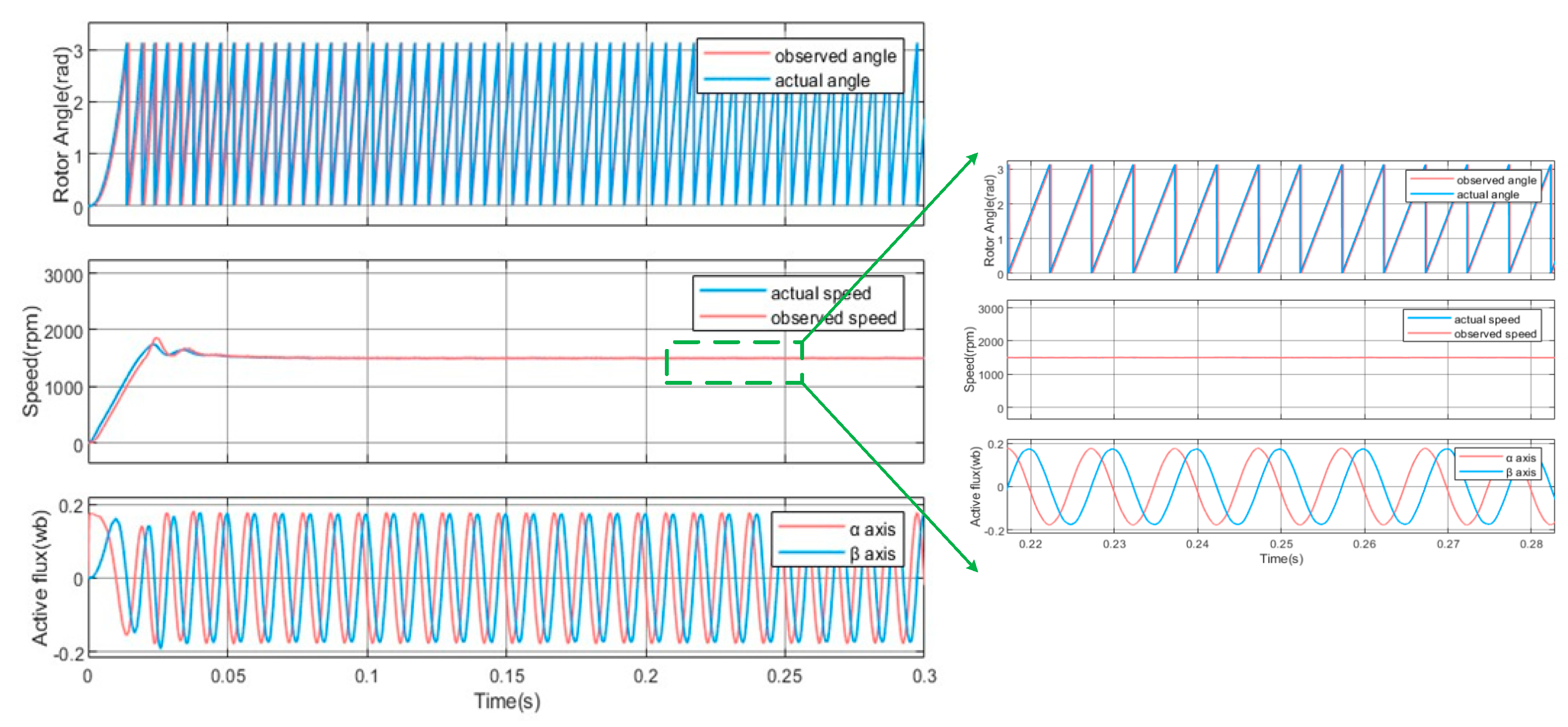
First, the sensorless control effect of the closed-loop active flux observer of the PMaSynRM at the rated speed was verified, as shown in
Figure 9.
Figure 9 (above) shows the waveforms of the actual angle and the observed angle. It can be seen that the error between the angle estimated by the observer and the actual rotor angle in steady state is very small, the waveforms of the two are basically overlapping, the observed value can track the actual value stably, and the position observation error does not exceed 3°;
Figure 9 (middle) shows the waveforms of the actual speed and the observed speed, and it can be seen that the motor operation presents good stability, and the steady-state speed error is kept within 2 rpm;
Figure 9 (below) shows the active flux waveform observed by the observer. The flux waveform of the α, β axis presents a 90° phase difference, and the amplitude is similar to the flux value of the permanent magnet, about 0.170 Wb, which fully verifies the theoretical expectation.
It is concluded that the active flux observer in the method of the invention can conveniently and accurately obtain the speed and position data of the motor when running at the rated speed, and the sensorless control method of the invention has good steady-state tracking performance and high estimation accuracy.
To verify the load carrying ability and anti-interference ability of the control method of the invention, the sensorless control effect of the PMaSynRM is verified under the working conditions of direct load and sudden load.
As shown in
Figure 10, the observed estimated angle value is in good agreement with the actual value under the load rated 15 N·m speed condition, showing good tracking performance. It is worth noting that although the load torque changes, it has little effect on the estimation accuracy, which indicates that the flux observer has a good load bearing performance in this case.
As shown in
Figure 11, the load torque 15 N·m is abruptly increased when t = 0.1 s at rated speed.
Figure 11 (above) shows the waveforms of the actual angle and observed angle before and after loading. Although the angle error increases at the loading moment, it can quickly return to a stable state, and the observed angle can then quickly and accurately track the actual angle.
Figure 11 (middle) shows the speed waveform between the observed speed and the actual speed of the system under the condition of sudden load. When the motor suddenly increases from no-load to rated load, the speed obviously decreases and becomes stable after a short oscillation, and the steady-state speed error is kept within 6 rpm.
Therefore, the method of the invention has strong anti-interference characteristics, and under the condition of load torque mutation, the sensorless control method of the invention can still maintain excellent tracking characteristics, and has good steady-state and dynamic performance.
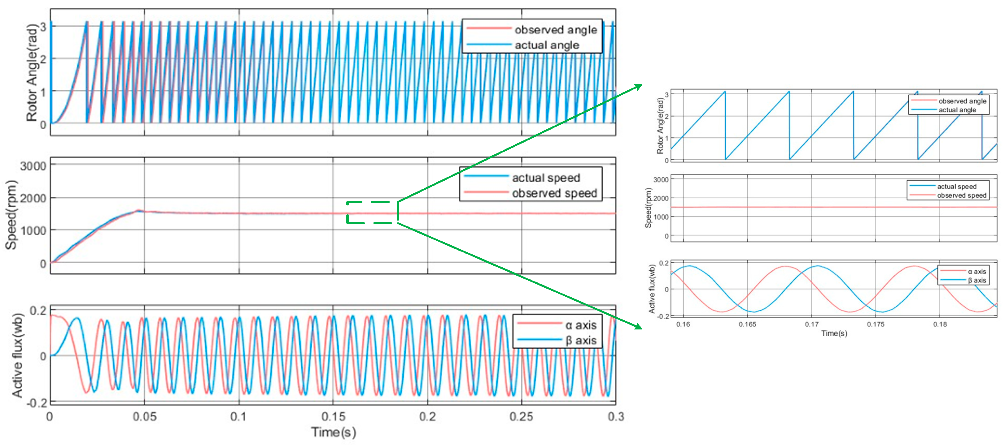
To verify the performance of the control method under low speed conditions, the sensorless control effect of the PMaSynRM is verified respectively under no-load, direct load and sudden load, as shown in
Figure 12,
Figure 13 and
Figure 14.
As shown in
Figure 12, it can be concluded that the control method of the invention exhibits good observation accuracy under low speed operation, significantly reduces the inaccuracy of angle estimation, and thus greatly improves the accuracy of position observation.
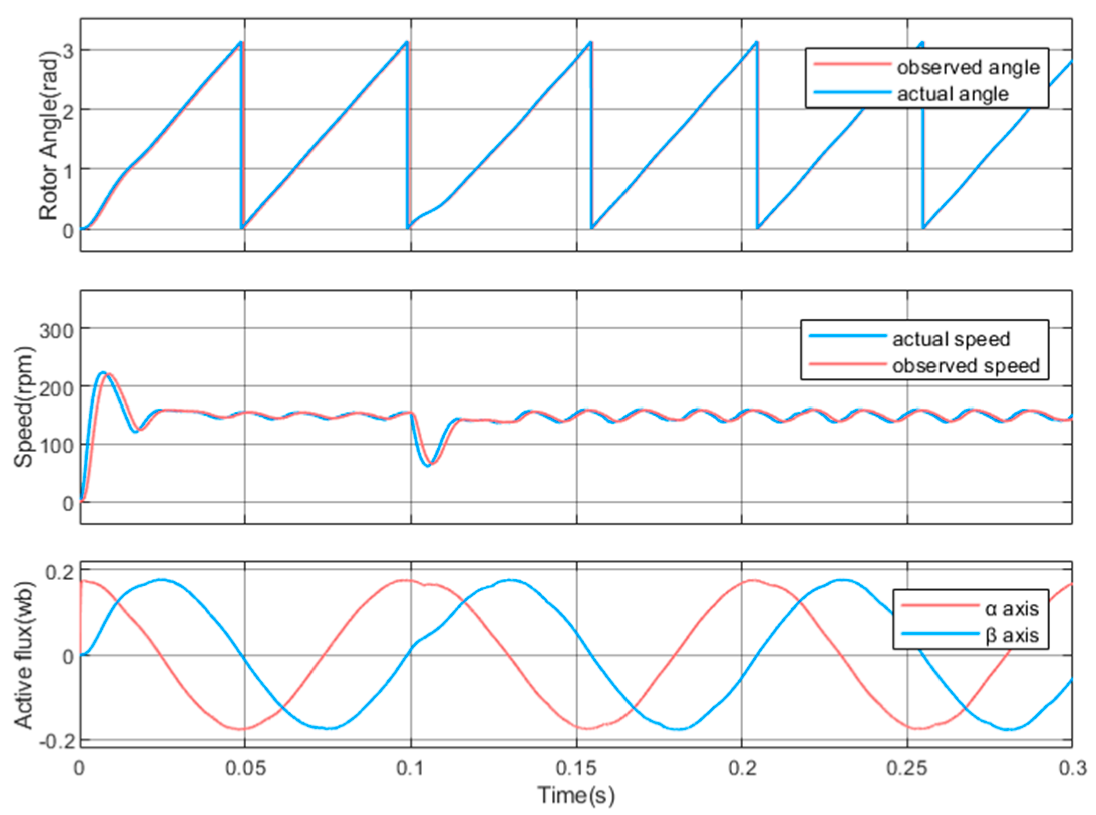
As shown in
Figure 13, compared with the no-load stage, the fluctuation of speed under load increases at low speed. At the same time, the presence of load torque disturbs the observation accuracy of the observer to a certain extent.
As shown in
Figure 14, when the motor suddenly increases the load torque 15 N·m from no-load, the speed presents a short decline, but becomes stable and maintains stable operation after closed-loop control adjustment. Compared with the no-load state, the fluctuation of speed under load is increased, but the fluctuation range is controlled within ±8 r/min.
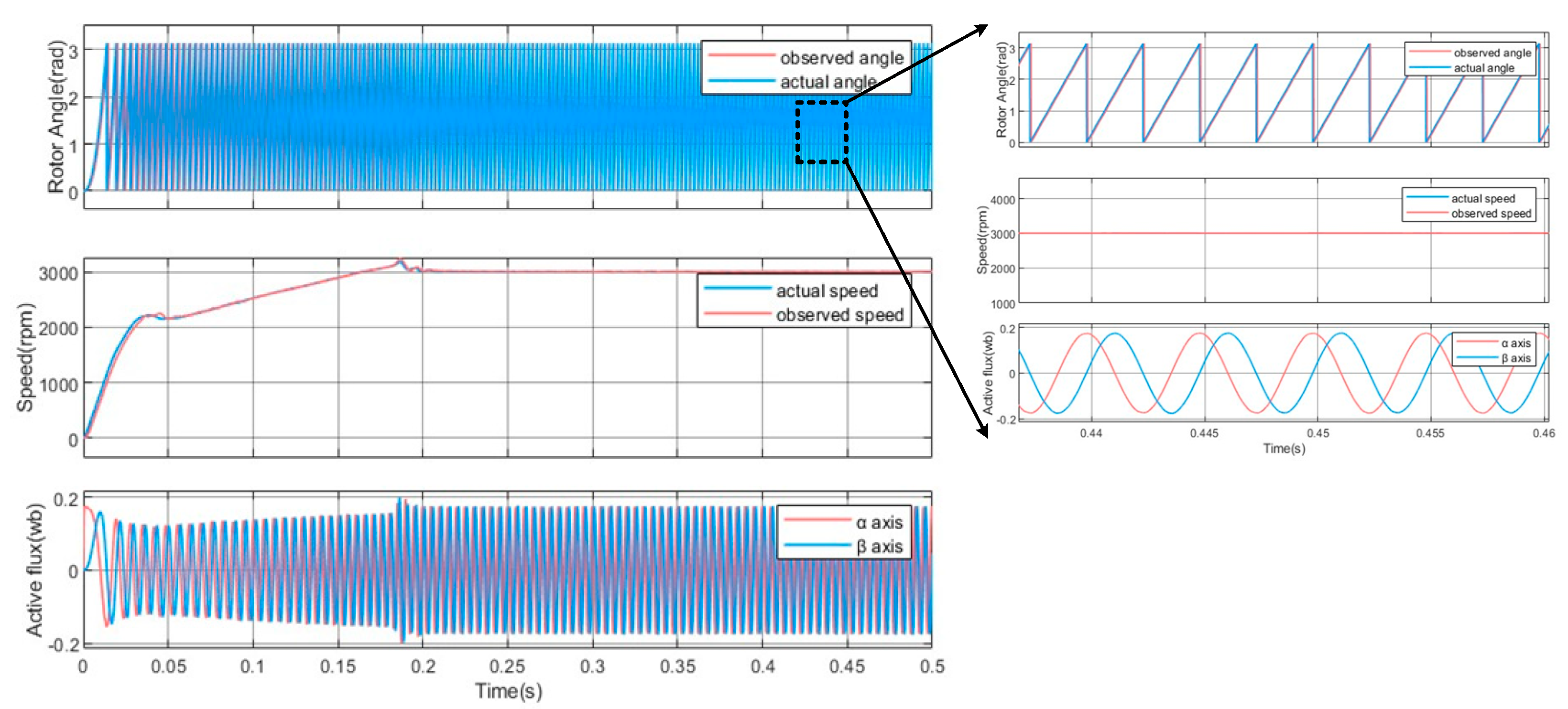
To verify the observation accuracy of the control method under medium and high speed operation, the sensorless control effect of the PMaSynRM is tested under no-load, direct load and sudden load respectively, as shown in
Figure 15,
Figure 16 and
Figure 17. The results show that the flux observer has a good observation effect on the steady state and the transient state of the motor under medium and high speed. The observed value can track the actual value stably and has a high observation accuracy.
5. Conclusions
This paper has proposed an active flux observer based on a hybrid model of VM and CM of sensorless control for PMaSynRM. The proposed method defines the active flux for the PMaSynRM model, and constructs the effective flux observer. Unlike traditional flux linkage method, the proposed flux observer takes the stator flux and the observed angle by the VM as the input of the CM, and outputs the estimated stator current after feeding into the current model. The stator current error is adjusted by PI and fed back to the voltage model to complete the closed-loop control. At the same time, the angle observed by the observer is used in the current model to achieve a more complete closed-loop feedback. The feasibility of the above scheme is verified on the simulation platform. Under the rated speed, the position observation error does not exceed 3°, and the steady-state speed error is kept within 2 rpm at no-load condition; the observed angle can quickly and accurately track the actual angle, and the steady-state speed error is kept within 6 rpm under load and sudden loading. Under the conditions of low and high speed operation, the flux observer shows good observation effect in both steady state and transient state, and the observed value can track the actual value stably, which greatly improves the accuracy of position observation. The results show that the proposed method can realize the stable operation of PMaSynRM in a wide speed range under sensorless conditions, improve the stability and accuracy of sensorless control, improve the system load capacity and anti-interference ability, and provide a feasible solution for many industrial applications.


 ,
, 


