Abstract
This paper investigates the secure communication in the reconfigurable intelligent surface (RIS)-aided cell-free massive multiple-input multiple-output (CF-mMIMO) system in the presence of an eavesdropper (Eve). Since the RIS can only reflect the incident signal from its front, we define the RIS coverage and non-coverage area based on whether the incident signals can be reflected. The RIS coverage area is affected by the deployment position and rotation angle, and thus, we take both of these two factors into account and a closed-form approximation for the ergodic secrecy rate of the legitimate user is derived. Based on it, the optimal RIS deployment position and phase shift are obtained through an alternating iteration method, and the optimal RIS angle is achieved through an exhaustive enumeration of angles with a certain interval. Simulations confirm that our optimal RIS deployment can achieve a superior secrecy rate. We find that to guarantee the best secrecy rate, the RIS should be placed near the target user, and its rotation angle should be adjusted to make as many access points (APs) as possible within the RIS coverage area.
1. Introduction
The cell-free massive multiple-input multiple-output (CF-mMIMO) technology has become a representative of the sixth-generation wireless communications’ (6G) new network architecture and an important trend in the development of 6G thanks to its advantages of superior performance and flexible deployment [1,2,3]. The CF-mMIMO technology can use densely deployed access points (APs) to eliminate cell boundary restrictions and alleviate the serious inter-cell interference in traditional massive MIMO systems [4,5,6]. Due to the inherent broadcast nature of wireless signals, any user in the CF-mMIMO system is theoretically able to receive the wireless signal and launch eavesdropping [7]. Because the APs trust and cooperate with each other, the eavesdropper (Eve) gives a higher communication risk in CF-mMIMO. Reconfigurable intelligent surface (RIS) finds a way to tackle this problem at a low cost [8]. RIS integrates a large number of low-cost passive reflective components with phase-shift controllers to reflect the incident signal in the desired direction [9,10], and can effectively increase the signal strength of target users and weaken that of Eves by adjusting the phase of the reflective components [11].
Although the absence of CF-mMIMO technology can increase the system capacity, the cost and power consumption both increase due to distributed APs and the fronthaul. By using RIS, the hardware and energy consumption can be significantly reduced. In [12], the authors proposed a joint precoding design problem in a broadband RIS-assisted CF-mMIMO system. By jointly optimizing precoding at the AP and RIS, significant system capacity gains are achieved. In [13], the authors derived the minimum mean-squared error estimation of the effective channel and the closed-form expression of the downlink throughput in a CF-mMIMO system with multiple RISs deployed. The simulation results proved the improvement effect of RIS on system capacity and the accuracy of the closed-form expression of downlink throughput. In [14], the authors considered the uplink spectral efficiency of a CF-mMIMO system under more realistic channel conditions with spatial correlation. The closed-form expression derived by the authors for the uplink spectral efficiency illustrates that the spatial correlation of RIS has a significant impact on the system.
The issue of RIS-aided secure communication has also aroused significant concern among scholars. In [15], the authors considered an RIS-assisted multiple-input single-output system where illegal users attempted to eavesdrop confidential information from APs intended for specific legitimate users. The optimal AP beamforming and RIS phase shift were obtained to maximize the sum secrecy rate of all legitimate users. Building upon this work, ref. [16] proposed a projection gradient descent algorithm to further enhance the secrecy rate of legitimate users. In [17], the authors introduced a bidirectional secure communication system assisted by RIS, which utilized a signal from legitimate users to interfere with the eavesdropping behavior of illegal users. In [18], the authors studied the physical layer security of wireless power communication (WPC) systems using RIS in the presence of passive Eves, and proposed three deployment schemes for RIS. For each scheme, the optimal phase shift was designed to maximize the reception of energy and information at the legitimate receiver.
The potential of RIS in improving the secure communication has been explored in CF-mMIMO systems. In [19], the authors analyzed the effectiveness of RIS in enhancing the security of CF-mMIMO systems in the presence of active pilot attacks by Eves. The optimal AP power allocation and RIS phase shift were obtained to ensure a certain quality of service for the legitimate users through minimizing their leakage rates. The authors in [20] proposed a joint optimization scheme for the beamforming of APs and the phase shift of RIS with the goal of maximizing the weighted sum secrecy rate of all users. It showed that there was a trade-off among the system performance, complexity and overhead in the proposed CF-mMIMO systems. In [21], the author further considered more challenging situations where the Eve was equipped with multiple antennas. The author designed a joint precoding framework based on imperfect channel-state information (CSI) with the goal of maximizing the system sum rate, and applied the alternating algorithm to obtain the optimal precoding and RIS phase shift. The work [22] considered an AP equipped with low-resolution analog-to-digital converters. In order to reduce the overhead of uplink training, an aggregated channel estimation scheme was proposed to jointly estimate direct and indirect channels.
However, all the above works do not consider the effect of RIS position and rotation angle. In the work [23], the author analyzed the cell coverage of the RIS-aided traditional massive MIMO system, which is defined as an area where the signal-to-noise ratio (SINR) received by the user is larger than a certain threshold. The mathematical expression indicated that the position and rotation angle of the RIS are two influencing factors for its cell coverage. By solving the cell coverage maximization problem, the optimal position and rotation angle were obtained. As shown in [24], the deployment position of RIS between the AP and user equipment (UE) can greatly affect the system performance and the optimal RIS location to maximize the received signal power, which depends on the relationship between the distance from BS to UE and the distance from RIS to the BS-UE line. Reference [25] pointed out that RIS deployment position optimization for wireless communication systems can maximize the overall data flow and minimize the number of RISs at the same time. In CF-mMIMO systems, APs are more densely and widely distributed, and thus, the deployment issues of RIS will be more complex. Unfortunately, no relevant research on RIS position and rotation angle for the secure communication in CF-mMIMO systems has emerged yet. In addition, our paper defines the coverage area of RIS differently and considers a distinct practical problem as well. In this paper, we study the secure communication in the RIS-aided CF-mMIMO system in the presence of an Eve. Our contributions can be summarized as follows:
(1). We adopt a more accurate model, which considers both the RIS position and rotation angle for the secure communication analysis. Hence, users and APs can be categorized into different groups, according to whether they can be reflected by the RIS. A closed-form approximation of the ergodic secrecy rate is derived, which helps us quickly estimate the secure communication performance.
(2). Based on the closed-form approximation of the ergodic secrecy rate, the optimal RIS deployment position and phase shift are obtained through an alternating iteration method. The convergence of the algorithm is proved theoretically.
(3). Simulations have verified that our optimal RIS deployment can significantly improve the secrecy rate. Moreover, we find that to guarantee the best secure communication, the RIS should be deployed around the target user and the rotation angle should make most APs be within the RIS coverage area.
Organization: In Section 2, we describe the scenario and channel condition of this paper, and establish a system model based on this. In Section 3, we give the expression of the received signals for both the users and Eve, and then obtain the ergodic secrecy rate of the target user. In Section 4, we present the optimization problems addressed and provide corresponding solutions. In Section 5, we present several simulations and analysis results to demonstrate the feasibility and superiority of the proposed solution method. In Section 6, we list some development directions of future work. In Section 7, we provide a brief summary of the work process and final conclusion obtained in this paper.
Notation: In this paper, boldface letters indicate matrices or vectors. denotes a complex matrix with dimension . , , and denote transpose, conjugate transpose, and conjugate of matrix , respectively. represents the i-th element of vector . , , and denote the mathematical expectation operator, diagonal operator, and modulus operator, respectively. e refers to the natural constant and is the logarithmic operator with a base of 2. is the identity matrix with dimension L.
2. System Model
We consider an RIS-aided CF-mMIMO system with M APs, K users, an RIS composed of L reflective components, and an Eve who randomly selects an eavesdropping target. The APs, users, and Eve are all equipped with a single antenna and are randomly located in a plane area. All APs connect to the CPU through a backhaul link. As the RIS can only reflect the incident signals from its front side, we define the RIS coverage area as the region where the signals can be reflected by the RIS. If an AP or user is located in the non-coverage area, it cannot transmit or receive any reflected signals from the RIS. Hence, the deployment position and rotation angle of the RIS directly determine the RIS coverage area, as shown in Figure 1. In the following, we implement both of the RIS position and rotation angle into the analysis.

Figure 1.
The reconfigurable intelligent surface (RIS)-aided cell-free massive multiple-input multiple-output (CF-mMIMO) system with an eavesdropper (Eve).
All the direct links (from APs to users/the Eve) and reflective links (from APs to the RIS and from the RIS to users/the Eve) exist. To accurately model the complex wireless environment, we chose different channel models for the direct and reflective links based on their unique characteristics and the impact of the RIS on the communication system. Due to the abundant scatterers between the AP and user, the direct link between them can be modeled as a Rayleigh channel [26]. The direct link from the m-th AP to the k-th user is denoted as
and the direct link from the m-th AP to the Eve is denoted as
where and , respectively, represent the large-scale fading coefficients from the m-th AP to the k-th user and the Eve; and are the corresponding small-scale fading coefficients which follow independent and identically distributed (i.i.d.) complex Gaussian distribution with zero means and unit variances. As for the reflective links, the line-of-sight (LoS) occurs more frequently due to the proximity between RIS and both the user and the AP. Hence, we model the reflective links as Ricean fading [27]. Then, the channel links from the m-th AP to the RIS and from the RIS to the k-th user are denoted as
respectively, where , and are the corresponding large-scale fading coefficients; and are the corresponding Rician K-factors. The channel link from the RIS to the Eve is denoted as
where and are the corresponding large-scale fading coefficient and Rician K-factor, respectively. In (3)–(5), represents the LoS components of and the l-th element is given as
Similarly, and can also be expressed as , , where , . Respectively, represents the angle of arrival of the m-th AP, while and represent the angles of departure of the k-th user and the Eve. , , and represent the non-LoS (NLoS) components of the Rician channels. In this paper, we assume a stable environment and the perfect CSI can be obtained via advanced channel estimation techniques [28]. The reflection phase matrix of RIS is a matrix used to represent its effect on the incident signals. Here, the reflection phase matrix of the RIS is represented by
where is the amplitude gain and is the reflective phase of the l-th reflective component of the RIS. We assume that the amplitude gain and phase shift of the RIS can be independently changed and the RIS has a unit amplitude gain in order to maximize its usefulness. Furthermore, each reflective component can be independently controlled.
3. Performance Analysis
In this section, we analyze the ergodic secrecy rate of the target user in the downlink transmission, and derive a closed-form approximation for it.
3.1. Downlink Secure Transmission
Let denote the transmit signal for the k-th user, which satisfies . Without loss of generality, we suppose that the k-th user is the Eve’s target user. The total channel from the m-th AP to the k-th user includes both the direct and reflective link, which is given as
where is the indicator to denote whether the reflective link exists. When the m-th AP and the k-th user are both in the coverage area of the RIS, ; otherwise, . We use the maximum ratio transmission due to its low complexity. The total transmit signal of the m-th AP is expressed as
where is the downlink transmit power of the AP. Thus, the received signal of the k-th user can be expressed as
where is the additive white Gaussian noise (AWGN) of the k-th user with zero mean and variance . The first term on the right side of (10) represents the desired signal, and the second term represents the interference from all other users. In addition, the signal leaked to the Eve can be described as
where represents for the total channel from the m-th AP to the Eve, is the indicator to denote whether the reflective link of the m-th AP and the Eve exists, and is the AWGN of the Eve with zero mean and variance .
3.2. Ergodic Secrecy Rate
From (10) and (11), the signal-to-interference-plus-noise ratio (SINR) of the k-th user can be calculated as
with the SINR of the Eve as follows:
Then, the ergodic secrecy rate of the k-th user is expressed as
The closed-form approximation of (14) is given in the following theorem.
Theorem 1.
The ergodic secrecy rate of the target user in (14) is approximated by
where and are given in (16) and (17), respectively,
where
, with
, ,
and ,
while ,
and with , .
Proof.
See Appendix A. □
The tightness and accuracy of Theorem 1 will be comprehensively verified in Section 5. In Equation (15), it becomes apparent that the ergodic secrecy rate is intricately linked to the relative positions of the access points (APs), the users, and the eavesdropper (Eve). Moreover, it is also effected by the RIS phase shift, as well as the position and rotation angle, as they determine whether the desired signal can be reflected by the RIS properly. In the subsequent sections, we will employ the approximation results provided in Equation (15) to derive the most effective RIS deployment strategy. This will involve the optimal settings for the RIS phase shift, position, and rotation angle to maximize the secrecy rate and improve the system’s overall performance.
4. RIS Deployment Optimization
In this section, our goal is to determine the optimal deployment of the reconfigurable intelligent surface (RIS) that maximizes the secrecy rate. Given that the rotation angle is implicit in the secrecy rate, we employ a dual approach for optimization. We use an alternating iteration method to optimize the RIS position and phase, and apply an exhaustive method to find the most suitable angle.
To begin, we will formulate the optimization problem with the objective of maximizing the secrecy rate. This formulation will consider various factors, including the RIS position, phase shift, and rotation angle, to ensure a holistic approach to optimizing the overall performance.
4.1. Problem Formulation
The proposed optimization problem of maximum secrecy rate can be formulated as follows:
where denotes the position coordinates of the RIS, denotes the rotation angle in degrees, A denotes the system deployment scope, and is composed of elements on the diagonal of . To ensure that other users can communicate normally at the same time, we need to ensure that the SINR of other users is greater than the threshold value . Here, we use to represent that is a function of , and .
The problem is difficult to solve directly due to the coupling of , , and , similarly to the non-convexity of the objective function. In order to overcome this dilemma, we first decompose the problem into three subproblems to decouple different variables in the objective function: the phase shift optimization, the position optimization, and the rotation angle optimization. Then, treating the phase shift and position as a whole entity, we fix one variable in each iteration of the subproblems and solve the other subproblem using the gradient descent method. As for the rotation angle, we use an exhaustive approach to select the optimal angle from a finite set of possible angles. The details will be given in the following subsection.
4.2. Problem Solution
(1) Position optimization: Firstly, we fix the phase shift matrix and the rotation angle to solve the position vector . That is, the problem can be simplified to
It is easy to see that there is only one variable in the problem , which greatly simplifies the origin problem. As is still non-convex, we use the gradient descent method to solve it. It should be noted that the RIS position must be limited to the region A. When the RIS position exceeds the region limitation during iteration, we need to roll it back in a certain length to the region and then continue our iteration. In each iteration, the previous gradient vector of and the search step are used to calculate the next RIS position vector until the secrecy rate converge.
(2) Phase shift optimization:Secondly, by fixing the RIS position vector and the rotation angle , we can rewrite the problem as the subproblem below:
Now the objective function is only a function of the phase shift matrix . The gradient descent method is also adopted to obtain the optimal phase shift matrix at any initial point with a fixed RIS position vector. In each iteration, the previous gradient vector of and the search step are used to calculate the next phase shift maxtrix until the secrecy rate converge.
(3) Rotation angle optimization:Thirdly, by fixing the position vector and the phase shift matrix , the problem becomes
Due to the rotation angle, whereby is implicit in the secrecy rate in (15), we cannot directly optimize it with the gradient descent method like RIS position or the phase shift. Other methods such as intelligent algorithms or heuristic optimization techniques that need explicit variables are also not applicable in this situation. For this purpose, we use an exhaustive method to take a rotation angle every within the range of to . Then, the optimal RIS position and phase shift corresponding to each angle, as well as the corresponding secrecy rate, will be obtained through the gradient descent method mentioned above. Finally, the set of angles, positions, and phase shifts that maximize the secrecy rate will be selected as our optimal result. The optimization of the RIS position vector and the phase shift matrix are alternately updated until the convergence of the objective function without variable is achieved, as shown in Algorithm 1. Here, we denote the gradient vector of objective function to the RIS position vector as , and denotes the gradient vector of objective function to the phase shift matrix. Without loss of generality, the initial values of and are both set to be random. As for the -th value of , we have . The proof of convergence for the gradient descent algorithm included in Algorithm 1 can be found in Appendix B.
| Algorithm 1 Algorithm for maximizing the secrecy rate of target user. |
|
5. Numerical Results
In this section, we validate the theoretial performance of the RIS-aided CF-mMIMO system. Without loss of generality, the APs, users, and the Eve are uniformly distributed in a square geographical region of size of .
In subsequent simulations, we set all the Rician K-factors , , and as 5 dB. As for the large-scale fading coefficients, we model them as , where d denotes the Euclid distance (in meters) and denotes the power attenuation factor. Specifically, we set , , , and . In order to ensure that other users can obtain a rate of no less than about 0.5 bit/s/Hz, we set the SINR threshold value . Unless otherwise specified, we set , , , and dBm, respectively.
In Figure 2, the simulated ergodic secrecy rate of the target user in (14) is compared with its closed-form approximation in (15). It is obvious that there exists a good match between the simulated and analytical results. We also find that the secrecy rate increases with the growth of the AP number while the rate decreases as the user number increases. This is because more APs can provide a more effective signal to the target user and more users can aggravate the severe inter-user interference to the target user. Considering the tightness of the simulation and analysis, we use the latter for the following investigation.
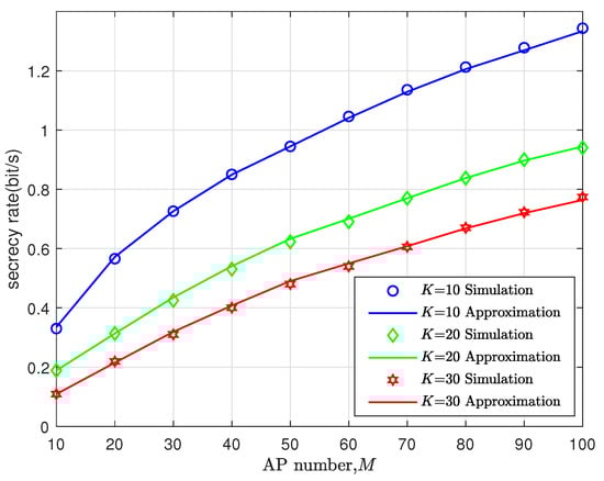
Figure 2.
Secrecy rate vs. access point(AP) number, where and dBm.
In Figure 3 and Figure 4, we show the gain brought by our optimal RIS deployment. The corresponding secrecy rates for several schemes are compared in Figure 3: without RIS; RIS with random position, phase shift, and rotation angle; RIS with optimal position, random phase shift, and rotation angle; RIS with optimal position, phase shift, and random rotation angle; and RIS with optimal position, phase shift, and rotation angle from the Algorithm. We can see that after introducing the RIS, the secrecy rate can be improved, but under a purely random situation, this improvement effect is not very significant. After optimizing the RIS phase shift and position with a fixed angle, the secrecy rate can be greatly enhanced further. When using Algorithm 1 to obtain the optimal RIS deployment, the secrecy rate is always the best. And in Figure 4, we can observe a direct correlation between the RIS coverage area and the AP distribution density, and how these factors affect the secrecy rate.

Figure 3.
Secrecy rate vs. AP transmit power, where , , and .
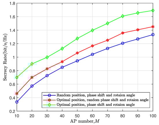
Figure 4.
Secrecy rate vs. AP number, where and dBm.
From Figure 5 and Figure 6, we can compare the optimal RIS position for the Eve selecting different target users while keeping the distribution of all APs and users unchanged. The black dashed line represents the boundary of the RIS coverage area. The region below the dashed line is covered, while the region above it is not. From the commonality between the two optimal RIS positions, we can infer that the RIS should be located close to the target user to ensure that the target user is within its coverage area. This deployment allows the reflective link built by the RIS to attenuate as little as possible, so that the target user is able to adequately benefit from the RIS.

Figure 5.
Optimal RIS positioning for different target user and Eve—Scenario 1.
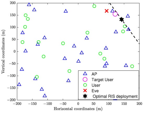
Figure 6.
Optimal RIS positioning for different target users and Eve—Scenario 2.
We further explore the impact of RIS rotation angle on the secrecy rate. In Figure 7, we show the secrecy rate under different rotation angles while maintaining the same optimal position in Figure 5. We enumerate several rotation angles and compare their corresponding secrecy rates. We can see that the rotation angle has a remarkable impact on the secrecy rate. The rotation angle results in the maximum secrecy rate because there are the most APs located within the RIS coverage area to serve the target user. Therefore, from Figure 5, Figure 6 and Figure 7, we know that to improve the secrecy rate of the target user, we should deploy the RIS near the target user and select an appropriate rotation angle to cover as many APs as possible.
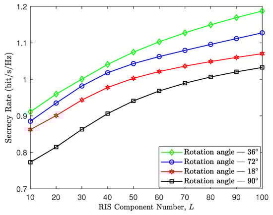
Figure 7.
Secrecy rate vs. RIS component number, where , , and dBm.
Through Figure 8, we show the convergence of the proposed optimization algorithm. It can be seen that the secrecy rates with different RIS component numbers all proceed to convergence after tens of iterations, which verifies the effectiveness of our algorithm. Moreover, we find that the more RIS components there are, the higher the iteration number required for the secrecy rate to reach convergence. This is because the hardware complexity of RIS increases with the number of its components.
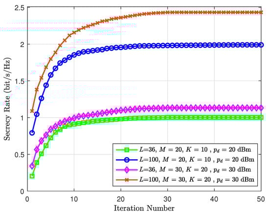
Figure 8.
Secrecy rate vs. iteration number.
6. Future Direction
In the future, we are considering research directions that involve selective cooperation among a subset of APs. This selective cooperation could potentially optimize the secure rate by focusing resources on the most effective APs for a given scenario, thereby improving the security of communications without compromising the overall system performance. Moreover, the combination of circularly polarized beam-scanning antennas with RIS offers a potent technological approach in the field of wireless communications cause its great potential for achieving omnidirectional radiation and frequency scanning [29,30], significantly improving system coverage and security, which is worthy of further research and exploration.
7. Conclusions
In this paper, we studied the secure communication in the RIS-aided CF-mMIMO system. Since the RIS position and rotation angle co-determine its coverage area, we took both of these factors into account. First of all, we derived a closed-form approximation of the ergodic secrecy rate. After that, the optimal position and phase shift corresponding to each exhausted rotation angles are obtained through alternating iteration methods. The optimal secrecy rate corresponding to each angle is compared and the rotation angle, position, and phase shift that maximizes the secrecy rate is selected as the optimal RIS deployment. Simulations have shown that the secrecy rate can be significantly improved with our optimal RIS deployment. Finally, we can conclude that we should deploy the RIS close to the target user and adjust its rotation angle to allow more APs within its coverage area.
Author Contributions
Writing—original draft preparation, J.Z.; writing—review and editing, Q.Z.; validation, T.A.; conceptualization, X.W.; methodology, F.P. All authors have read and agreed to the published version of the manuscript.
Funding
This research was funded by the National Natural Science Foundation of China under grant 62171231.
Data Availability Statement
Data are contained within the article.
Conflicts of Interest
The authors Xianhu Wei and Fengqiang Peng were employed by the company China Information Consulting & Design Institute Co., Ltd. The remaining authors declare that the research was conducted in the absence of any commercial or financial relationships that could be construed as a potential conflict of interest.
Abbreviations
The following abbreviations are used in this manuscript:
| CF-mMIMO | Cell-Free Massive Multiple-Input Multiple-Output |
| RIS | Reconfigurable Intelligent Surface |
| Eve | Eavesdropper |
| UAV | Unmanned Aerial Vehicle |
| AP | Access Point |
| UE | User Equipment |
| WPC | Wireless Power Communication |
| SINR | Signal-to-Noise Ratio |
| CPU | Central Processing Unit |
| LoS | Line-of-Sight |
| NLoS | Non-LoS |
| CSI | Channel-State Information |
Appendix A. Proof of Theorem 1
According to the Lemma 1 in [31], we have that
where
and
Here, the numerator and denominator in the formula are both divided by the transmit power . Firstly, we disassemble the numerator of (A2) into two parts:
The expectation in the first item to the right of (A4) can be calculated as
according to (5) in [32]. The expectation in the second item to the right of (A4) can be calculated as
where we use the independence among , , and . Secondly, we disassemble the numerator of (A2) into two parts:
Through a calculation process similar to (A6), we obtain
Further, we have because and . It should be noted that and are independent as long as one of or holds. Then, the expectation in the second item to the right of (A7) can be calculated as
Since the desired signal obtained by the Eve is essentially a special inter-user interference from the target user, we only need to follow the calculation of (A7) to obtain
Appendix B. Proof of the Convergence of the Algorithm
According to the L-Lipschitz condition, we have
where is the gradient vector of the objective function on point . Since the value of the objective function carries practical physical significance, is a finite constant. Taking the derivative of on both sides of the inequality, we then obtain . For the second-order Taylor expansion of the objective function, we obtain
Now, we assume that and substitute it into (A12) to yield
Taking , then
Finally, we obtain
In (A15), we can see that every iteration will make smaller because and
are both positive. In this way, the optimal result will gradually be obtained. So far, we have completed the proof of the convergence of the RIS position iteration.
To prove the convergence of RIS phase shift iteration, one can follow a similar approach as described above by simply replacing the independent variable in the derivation process with the RIS phase shift matrix . Due to space limitations, the detailed process is omitted here.
References
- Zhang, J.; Chen, S.; Lin, Y.; Zheng, J.; Ai, B.; Hanzo, L. Cell-Free Massive MIMO: A New Next-Generation Paradigm. IEEE Access 2019, 7, 99878–99888. [Google Scholar] [CrossRef]
- Lancho, A.; Durisi, G.; Sanguinetti, L. Cell-Free Massive MIMO for URLLC: A Finite-Blocklength Analysis. IEEE Trans. Wirel. Commun. 2023, 22, 8723–8735. [Google Scholar] [CrossRef]
- Zhou, L.; Leng, S.; Wang, Q.; Liu, Q. Integrated Sensing and Communication in UAV Swarms for Cooperative Multiple Targets Tracking. IEEE Trans. Mob. Comput. 2023, 22, 6526–6542. [Google Scholar] [CrossRef]
- Ammar, H.A.; Adve, R.; Shahbazpanahi, S.; Boudreau, G.; Srinivas, K.V. User-Centric Cell-Free Massive MIMO Networks: A Survey of Opportunities, Challenges and Solutions. IEEE Commun. Surv. Tutor. 2022, 24, 611–652. [Google Scholar] [CrossRef]
- Zheng, J.; Zhang, J.; Du, H.; Niyato, D.; Ai, B.; Debbah, M.; Letaief, K.B. Mobile Cell-Free Massive MIMO: Challenges, Solutions, and Future Directions. IEEE Wirel. Commun. 2024, 31, 140–147. [Google Scholar] [CrossRef]
- Zeng, J.; Wu, T.; Song, Y.; Zhong, Y.; Lv, T.; Zhou, S. Achieving Energy-Efficient Massive URLLC over Cell-Free Massive MIMO. IEEE Internet Things J. 2024, 11, 2198–2210. [Google Scholar] [CrossRef]
- Zhai, L.; Zou, Y.; Zhu, J.; Li, B. Improving Physical Layer Security in IRS-Aided WPCN Multicast Systems via Stackelberg Game. IEEE Trans. Commun. 2022, 70, 1957–1970. [Google Scholar] [CrossRef]
- Demir, Ö.T.; Masoudi, M.; Björnson, E.; Cavdar, C. Cell-Free Massive MIMO in O-RAN: Energy-Aware Joint Orchestration of Cloud, Fronthaul, and Radio Resources. IEEE J. Sel. Areas Commun. 2024, 42, 356–372. [Google Scholar] [CrossRef]
- Wang, R.; Yang, Y.; Makki, B.; Shamim, A. A Wideband Reconfigurable Intelligent Surface for 5G Millimeter-Wave Applications. IEEE Trans. Antennas Propag. 2024, 72, 2399–2410. [Google Scholar] [CrossRef]
- Yang, S.; Xie, C.; Lyu, W.; Ning, B.; Zhang, Z.; Yuen, C. Near-Field Channel Estimation for Extremely Large-Scale Reconfigurable Intelligent Surface (XL-RIS)-Aided Wideband mmWave Systems. IEEE J. Sel. Areas Commun. 2024, 42, 1567–1582. [Google Scholar] [CrossRef]
- Zhou, G.; Pan, C.; Ren, H.; Wang, K.; Peng, Z. Secure Wireless Communication in RIS-Aided MISO System with Hardware Impairments. IEEE Wirel. Commun. Lett. 2021, 10, 1309–1313. [Google Scholar] [CrossRef]
- Zhang, Z.; Dai, L. A Joint Precoding Framework for Wideband Reconfigurable Intelligent Surface-Aided Cell-Free Network. IEEE Trans. Signal Process. 2021, 69, 4085–4101. [Google Scholar] [CrossRef]
- Nguyen, N.T.; Nguyen, V.D.; Nguyen, H.V.; Ngo, H.Q.; Chatzinotas, S.; Juntti, M. Downlink Throughput of Cell-Free Massive MIMO Systems Assisted by Hybrid Relay-Reflecting Intelligent Surfaces. In Proceedings of the ICC 2022—IEEE International Conference on Communications, Seoul, Republic of Korea, 16–20 May 2022; pp. 1475–1480. [Google Scholar]
- Shi, E.; Zhang, J.; He, R.; Jiao, H.; Wang, Z.; Ai, B.; Ng, D.W.K. Spatially Correlated Reconfigurable Intelligent Surfaces-Aided Cell-Free Massive MIMO Systems. IEEE Trans. Veh. Technol. 2022, 71, 9073–9077. [Google Scholar] [CrossRef]
- Cui, M.; Zhang, G.; Zhang, R. Secure Wireless Communication via Intelligent Reflecting Surface. IEEE Wirel. Commun. 2019, 8, 1410–1414. [Google Scholar] [CrossRef]
- Feng, B.; Wu, Y.; Zheng, M. Secure Transmission Strategy for Intelligent Reflecting Surface Enhanced Wireless System. In Proceedings of the 2019 11th International Conference on Wireless Communications and Signal Processing (WCSP), Xi’an, China, 23–25 October 2019; pp. 1–6. [Google Scholar]
- Lv, L.; Wu, Q.; Li, Z.; Al-Dhahir, N.; Chen, J. Secure Two-Way Communications via Intelligent Reflecting Surfaces. IEEE Commun. Lett. 2021, 25, 744–748. [Google Scholar] [CrossRef]
- Cao, K.; Ding, H.; Lv, L.; Su, Z.; Tao, J.; Gong, F.; Wang, B. Physical-Layer Security for Intelligent-Reflecting-Surface-Aided Wireless-Powered Communication Systems. IEEE Internet Things J. 2023, 10, 18097–18110. [Google Scholar] [CrossRef]
- Elhoushy, S.; Ibrahim, M.; Hamouda, W. Exploiting RIS for Limiting Information Leakage to Active Eavesdropper in Cell-Free Massive MIMO. IEEE Wirel. Commun. Lett. 2022, 11, 443–447. [Google Scholar] [CrossRef]
- Hao, W.; Li, J.; Sun, G.; Zeng, M.; Dobre, O.A. Securing Reconfigurable Intelligent Surface-Aided Cell-Free Networks. IEEE Trans. Inf. Forensics Secur. 2022, 17, 3720–3733. [Google Scholar] [CrossRef]
- Hu, H.; Xie, W.; Xu, K.; Xia, X.; Wang, M.; Liu, S.; Li, N. Secure Downlink Transmission in Cell-Free Massive MIMO System Enhanced by Intelligent Reflecting Surfaces. Secur. Commun. Netw. 2022, 2022, 25–39. [Google Scholar] [CrossRef]
- Zhang, X.; Liang, T.; An, K.; Yang, H.; Niu, C. Secure Transmission in RIS-Assisted Cell-free Massive MIMO system with Low Resolution ADCs/DACs. In Proceedings of the 2022 IEEE Wireless Communications and Networking Conference (WCNC), Austin, TX, USA, 10–13 April2022; pp. 339–344. [Google Scholar]
- Zeng, S.; Zhang, H.; Di, B.; Han, Z.; Song, L. Reconfigurable Intelligent Surface (RIS) Assisted Wireless Coverage Extension: RIS Orientation and Location Optimization. IEEE Commun. Lett. 2021, 25, 269–273. [Google Scholar] [CrossRef]
- Ren, Y.; Zhou, R.; Teng, X.; Meng, S.; Zhou, M.; Tang, W.; Li, X.; Li, C.; Jin, S. On Deployment Position of RIS in Wireless Communication Systems: Analysis and Experimental Results. IEEE Wirel. Commun. 2023, 12, 1756–1760. [Google Scholar] [CrossRef]
- Khaled, A.; Alwakeel, A.S.; Shaheen, A.M.; Fouda, M.M.; Ismail, M.I. Placement Optimization and Power Management in a Multiuser Wireless Communication System with Reconfigurable Intelligent Surfaces. IEEE Open J. Commun. Soc. 2024, 5, 4186–4206. [Google Scholar] [CrossRef]
- Wu, Y.; Huo, Y.; Gao, Q.; Mao, J.; Yang, Z.; Jing, T. Secure Uplink Transmission Against Multiintelligent Eavesdroppers with Time-Domain Artificial Noise in MIMO IoT Systems. IEEE Internet Things J. 2024, 11, 31662–31674. [Google Scholar] [CrossRef]
- Dong, X.; Fei, Z.; Wang, X.; Hua, M.; Wu, Q. STAR-RIS Aided Secure MIMO Communication Systems. IEEE Trans. Veh. Technol. 2024, 73, 15715–15720. [Google Scholar] [CrossRef]
- Zhou, G.; Pan, C.; Ren, H.; Xu, D.; Zhang, Z.; Wang, J.; Schober, R. A Framework for Transmission Design for Active RIS-Aided Communication with Partial CSI. IEEE Trans. Wirel. Commun. 2024, 23, 305–320. [Google Scholar] [CrossRef]
- Wang, S.; Chung, K.L.; Kong, F.; Du, L.; Li, K. A Simple Circularly Polarized Beam-Scanning Antenna Using Modulated Slotline-Spoof Surface Plasmon Polariton Slow-Wave Transmission Line. IEEE Antennas Wirel. Propag. Lett. 2023, 22, 1109–1113. [Google Scholar] [CrossRef]
- Lee, H.; Choi, J.H.; Wu, C.T.M.; Itoh, T. A Compact Single Radiator CRLH-Inspired Circularly Polarized Leaky-Wave Antenna Based on Substrate-Integrated Waveguide. IEEE Trans. Antennas Propag. 2015, 63, 4566–4572. [Google Scholar] [CrossRef]
- Zhang, Q.; Jin, S.; Wong, K.K.; Zhu, H.; Matthaiou, M. Power Scaling of Uplink Massive MIMO Systems with Arbitrary-Rank Channel Means. IEEE J. Sel. Top. Signal Process. 2014, 8, 966–981. [Google Scholar] [CrossRef]
- Hoang, T.M.; Ngo, H.Q.; Duong, T.Q.; Tuan, H.D.; Marshall, A. Cell-Free Massive MIMO Networks: Optimal Power Control Against Active Eavesdropping. IEEE Trans. Commun. 2018, 66, 4724–4737. [Google Scholar] [CrossRef]
Disclaimer/Publisher’s Note: The statements, opinions and data contained in all publications are solely those of the individual author(s) and contributor(s) and not of MDPI and/or the editor(s). MDPI and/or the editor(s) disclaim responsibility for any injury to people or property resulting from any ideas, methods, instructions or products referred to in the content. |
© 2025 by the authors. Licensee MDPI, Basel, Switzerland. This article is an open access article distributed under the terms and conditions of the Creative Commons Attribution (CC BY) license (https://creativecommons.org/licenses/by/4.0/).