Abstract
A multivector direct model predictive control (DMPC) scheme is proposed for the dual three-phase permanent magnet synchronous machine (DTP-PMSM) drive system to achieve closed-loop control for both fundamental current tracking and harmonic current minimization. The proposed multivector DMPC scheme employs four active voltage vectors, including two large vectors and two basic vectors for implicit modulation. Moreover, the control optimization problem is formulated as a four-dimensional quadratic programming problem, which is suitable for real-time implementation. The proposed multivector DMPC scheme enables fast and accurate tracking of the fundamental current as well as effective suppression of harmonic currents in both the fundamental and harmonic subspaces. In addition, a Kalman filter observer is incorporated to enhance robustness against model uncertainties and disturbances. Experimental results on a DTP-PMSM test bench verify that the proposed multivector DMPC scheme effectively reduces torque ripple, improves current quality, and enhances both steady-state and transient performance of the system.
1. Introduction
In recent years, with the rapid development of power converters, electric machines are no longer constrained by traditional three-phase power systems. As a result, multiphase machines have attracted increasing attention and have been widely applied. Compared with conventional three-phase drive systems, multiphase electric drive systems offer several advantages, including low-voltage high-power capability, reduced torque ripple, excellent fault tolerance, and increased control degrees of freedom [1,2]. These advantages have promoted the adoption of multiphase machines in medium-voltage (MV) and high-power industrial scenarios such as electric vehicles, wind power generation, drones [3,4,5], and electric ships [6,7]. Among multiphase machines, the asymmetrical dual three-phase permanent magnet synchronous machine (DTP-PMSM) has become a representative solution due to its high-power density and the combination of benefits from both three-phase and multiphase machines [8].
However, current harmonics induced by back electromotive force (EMF), inverter nonlinearities, and manufacturing asymmetries become more significant, which can increase the electromagnetic torque ripple and reduce the overall efficiency of the drive system [9]. Therefore, it is necessary to design and develop suitable control algorithms. As an emerging control approach, model predictive control (MPC) has shown great promise. MPC can be straightforwardly applied to multivariable and multi-objective systems, allows for the direct inclusion of nonlinearities and multiple constraints, and offers fast dynamic response [10,11]. Direct MPC (DMPC), also known as finite control set MPC (FCS-MPC), is a widely studied method due to its simple structure and ability to directly generate optimal switching states for the inverter without intermediate modulation delays. However, because FCS-MPC applies only a single voltage vector per control interval, it struggles to accurately synthesize the desired reference voltage and simultaneously regulate harmonic currents.
To solve the problem, the multivector scheme is proposed, which employs multiple vectors acting together within one control cycle to improve control performance. In [12,13], the optimal vector and the zero vector act together, and the vector amplitude is adjusted by the duty cycle. However, this scheme cannot adjust the phase angle of the voltage vector, so the suppression effect on torque ripple is limited. To improve the issues, a generalized double-vector scheme is proposed in [14], which extends the second vector from the zero vector to any vector. Both its amplitude and phase angle can be adjusted by vector synthesis, and thus, better control performance is achieved. In addition, to further expand the coverage of output vectors, a combination of two effective vectors and one zero vector is used in [15]. A virtual voltage vector with adjustable amplitude and phase angle is synthesized by these three voltage vectors. However, for the DTP-PMSM drive systems, the aforementioned schemes mainly focus on the control of the fundamental plane while neglecting the control of the harmonic plane. For DTP-PMSMs, the use of middle and large vectors to synthesize virtual vectors with zero magnitude in the harmonic plane has been proposed to improve harmonic current suppression [16,17]. Although this method can achieve average zero-sequence voltage, it suffers from several drawbacks, such as reduced DC bus voltage utilization, unfixed switching frequency, injection of additional second-order harmonics, and a limited control set leading to suboptimal solutions. To address these limitations, continuous control set MPC (CCS-MPC) approaches have been developed. For example, in [18,19], the methods based on two virtual vectors are proposed to form a continuous control set, enhancing current tracking and overall control performance. In [20], a virtual vector control method based on zero-vector optimization is presented, which expanded the control vector set and significantly improved both dynamic and steady-state performance. In [21], a CCS-MPC scheme based on a centrally symmetric pulse pattern is proposed. The scheme first divides the virtual vectors into three groups, then generates two virtual vectors and two zero-voltage vectors with optimized duty cycles through modulation. Ultimately, it achieves the improvement of steady-state performance and the simplification of hardware implementation. Even so, issues such as low DC bus voltage utilization and the inability to achieve effective harmonic suppression due to the open-loop control of the harmonic plane still remain. To increase DC bus voltage utilization, enable full synthesis of voltage vectors within the linear modulation region, and simultaneously retain the advantages of DMPC, the pre-synthesis of virtual vectors before modulation may be possible to eliminate. In [22], a DMPC scheme employing four large vectors for implicit modulation is proposed. The scheme achieves closed-loop control of both the fundamental and harmonic planes, thereby realizing lower harmonic distortion and better steady-state performance. In [23], a method based on distributing the dwell times of three adjacent large vectors and the zero vector is introduced to achieve closed-loop control of harmonic currents. However, the switching patterns in the aforementioned control schemes involve multiple switching actions or require equal phase duty-ratio conversion into a centrally symmetric single pulse. Typically, this results in an average of 4/3 switching actions per switch within each modulation cycle. This leads to increased difficulty in hardware implementation or inconsistency between the actual output voltage vectors and the resultant vectors calculated by the scheme.
Motivated by the above, this paper proposes a multivector DMPC scheme for DTP-PMSMs that achieves favorable steady-state and transient performance while enabling effective harmonic current suppression. The proposed multivector DMPC scheme employs four active voltage vectors—two large vectors and two basic vectors—together with the zero vectors, to participate in implicit modulation. And the resulting control optimization problem is formulated as a quadratic programming problem that is suitable for real-time implementation. These enable accurate synthesis of arbitrary reference voltage vectors across the entire linear modulation region, along with effective control in the harmonic plane. These also enable obtaining a symmetric switching pattern with a single switching action per cycle during modulation, without the need for equal phase duty-ratio conversion. A fixed switching frequency equal to the control frequency is achieved. The proposed multivector DMPC scheme can effectively minimize torque ripple and xy-axis currents while ensuring good dynamic performance and low switching losses. In addition, a Kalman filter observer is incorporated into the control system to compensate for modeling inaccuracies and external disturbances, thereby enhancing the robustness of the control algorithm. Finally, the effectiveness of the proposed approach is validated through experiments conducted on a DTP-PMSM drive test bench.
2. Mathematical Model
As shown in Figure 1, the studied electrical drive system consists of an asymmetrical DTP-PMSM and a six-phase two-level voltage source inverter (2L-VSI). To design a suitable control algorithm for the drive system, the mathematical models of the PMSM and the inverter are analyzed and derived in the discrete-time domain.
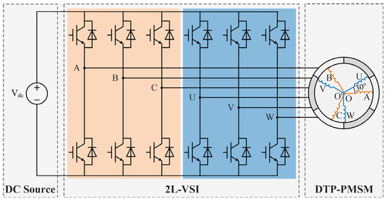
Figure 1.
Configuration of the 2L-VSI-fed DTP-PMSM drive.
2.1. Discrete Model of DTP-PMSM
The asymmetrical DTP-PMSM consists of two sets of three-phase stator windings, spatially displaced by 30 electrical degrees, with two isolated neutral points. The basic voltage and flux linkage equations of the DTP-PMSM in the natural coordinate system (ABCUVW) are given as
where , and represent the stator phase voltage, stator phase current, and stator phase flux linkage, and are the resistance and inductance coefficient matrices, is the flux linkage coefficient matrix, and is the amplitude of the fundamental component of the permanent magnet flux.
By applying Vector Space Decomposition (VSD), the mathematical model of the DTP-PMSM is fully decoupled. The variables of the DTP-PMSM are mapped into three mutually orthogonal subspaces: the αβ, xy, and o1o2 subspaces. Among these, the current components in the αβ subspace participate in energy conversion and generate electromagnetic torque. The current components in the xy subspace do not contribute to energy conversion but increase copper losses. The current components in the o1o2 subspace are zero under the condition of isolated neutral points. Therefore, the o1o2 subspace can be neglected in the VSD-decoupled model. After the αβ subspace is further transformed into the synchronous dq reference frame via the Park transformation, the state-space representation of the DTP-PMSM in the continuous-time domain is formulated as
where i, u and ω are the vectors of stator current, voltage and back electromotive force (EMF), and F and G are the state matrix and the input matrix. The corresponding expressions of these vectors are as follows:
where ωe is the rotor electrical angular speed Rs is the stator resistance, and Lq, Ldq and Lxy are the inductances of two sets of windings on the q-axis, the dq subspace and the xy subspace, respectively.
Based on the forward Euler method, the discrete-time state-space model is described as
where I is the identity matrix, A, B, and z are the discrete state matrix, discrete input matrix, and discrete back electromotive force vector, respectively, and TS is the sampling time.
2.2. Description of Six-Phase 2L-VSI
The adopted six-phase 2L-VSI consists of six bridge arms, each composed of an upper and a lower switching device, with complementary gate signals. The switching states of each bridge arm are denoted by SA, SB, SC, SU, SV, SW, where a value of 1 indicates that the upper switch is on and the lower switch is off, while 0 indicates the opposite. Therefore, the inverter has a total of 26 = 64 switching states, with each state corresponding to a space voltage vector, as shown in Figure 2. Each switching state is identified by two octal numbers, corresponding, respectively, to the binary numbers [SA SB SC] and [SU SV SW]. The projected magnitudes of each voltage vector in the αβ and xy planes are calculated as
where Vdc is the DC bus voltage. From (10), it can be derived that all 64 voltage vectors include 60 effective vectors and 4 zero vectors (00, 07, 70, 77). According to the differences in vector magnitudes, the effective vectors can be classified into four categories, namely large vectors, medium vectors, basic vectors, and small vectors. The projection magnitudes of the effective vectors on the αβ and xy planes are illustrated in Table 1.
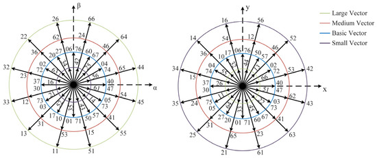
Figure 2.
Voltage vectors of six-phase 2L-VSI.

Table 1.
Voltage Vector Magnitudes.
3. The Proposed Multivector DMPC Scheme with Kalman Filter Observer
To achieve full voltage vector synthesis within the linear modulation region and provide improved harmonic suppression for the DTP-PMSM drive system, this paper proposes a multivector DMPC scheme. The closed-loop control process of the proposed multivector DMPC scheme is summarized graphically in Figure 3. For vector synthesis, four active voltage vectors, two large vectors and two basic vectors, are used. This realizes four-dimensional (4D) closed-loop control in both the fundamental and harmonic planes. The 4D control optimization problem is formulated as a quadratic programming problem, which is solved to obtain the duration of each vector. Thus, the converter switches can be directly manipulated, and a fixed and minimum switching frequency is achieved. In addition, a Kalman filter observer is added to the control system to eliminate errors caused by disturbances, thereby enhancing the robustness of the control scheme. The corresponding detailed descriptions are given as follows.
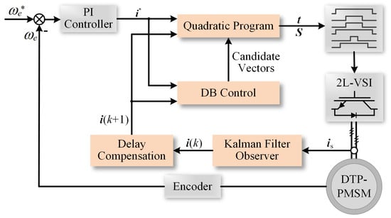
Figure 3.
Block diagram of proposed multivector DMPC scheme with Kalman filter observer.
3.1. Delay Compensation
In an ideal DMPC algorithm, the current at time step k is collected, and the prediction model is then used to calculate the predicted current at time step k + 1. The optimal switching state is determined through the evaluation of a cost function and is immediately applied at the current time step k, as illustrated in Figure 4a. However, in practical applications, the computation time required for the control algorithm must be considered. The process of obtaining the optimal switching sequence involves multiple model predictions and cost function evaluations. This introduces a significant time delay between the current sampling instant and the application of the latest switching state, as shown in Figure 4b. Due to this computational delay, the actual current at time step k continues to respond to the control signal from the previous time step, while the optimal switching state obtained at time step k is not applied until time step k + 1. It can be observed that this delay causes the actual current to deviate from the predicted trajectory, increasing current ripple.

Figure 4.
Predicted current under ideal and practical conditions: (a) ignoring computation delay, (b) considering computation delay, (c) applying delay compensation.
To mitigate the impact of the computational delay, the delay compensation scheme is applied in the control system as shown in Figure 4c. The main idea is to shift the prediction domain from (k, k + 1) to (k + 1, k + 2). After completing the current sampling at time step k, the optimal voltage vector stored from the previous step is used to calculate the predicted current at time step k + 1, based on (9). Then, starting from time k + 1, the predicted current at k + 2 is calculated, and the optimal voltage vector corresponding to the minimum cost function is determined. The optimal vector is stored as the output for the next control period.
3.2. Design of Control Algorithm
In the implicit modulation stage of the proposed multivector DMPC scheme, based on the four-dimensional model of the DTP-PMSM drive system, four active voltage vectors are selected to synthesize the desired voltage, thereby providing four control degrees of freedom. An ideal reference voltage vector is calculated using the deadbeat (DB) control algorithm without considering modulation constraints. The corresponding expression of the ideal reference voltage vector is given as
where is the reference current vector generated by the outer-loop proportional–integral (PI) speed controller. To synthesize the reference voltage vector within each control period, the αβ space vector plane is evenly divided into 12 sectors, and the sector in which the ideal reference voltage vector is located is identified. For each sector, two large vectors in the sector and two basic vectors from adjacent sectors are selected. The large vectors are chosen because they have the smallest magnitude in the xy plane, allowing maximum utilization of the DC-link voltage and reducing harmonic distortion. The basic vectors are selected because their switching states always include either ‘0’ or ‘7’, ensuring that each phase undergoes exactly one switching event per cycle. The selection of active vectors and redundant basic vectors for the 12 sectors is shown in Table 2.

Table 2.
The four selected active voltage vectors (two large and two basic vectors) for each sector.
To achieve four-dimensional current control in both the fundamental (dq) plane and the harmonic (xy) plane, the cost function is designed to include two control objectives, tracking error of the dq-axis currents and minimization of harmonic currents in the xy plane. The cost function is formulated as
where u(k + 1) is the actual voltage vector synthesized from the two selected large vectors, the two selected basic vectors, and zero vectors. In addition to the selected candidate vectors, the duration of each vector is also required to construct the reference voltage vector. Therefore, in the optimization problem for minimizing the cost function, the variables to be solved are the dwell times of all candidate vectors. The dwell times must be positive and their sum must equal the sampling period. The corresponding linear equations and constraints are formulated as
where ti are the dwell times of the zero vectors and the four active voltage vectors ui, and , , and are the components of the reference voltage vector on the α-, β-, x- and y-axes, and , , and are the components of the active vector ui.
Hence, the optimization problem is rewritten as
where t is the dwell times vector, Ttrans is the additional transformation matrix and Tpark is the matrix of the extended Park transformation. And they are represented as
where θe is the rotor electrical angle.
To calculate the dwell times vector t, the four-dimensional optimization problem is reformulated as a constrained quadratic programming problem, which can be efficiently solved in real time. The constrained quadratic programming problem is expressed as
3.3. Generation of Switching Positions
Through the proposed control algorithm, both the candidate voltage vectors and their corresponding dwell times can be obtained, enabling the generation of the optimal switching sequence for the power devices within a single control period.
Based on the principle of generating an 11-segment, center-aligned switching pattern, each phase is required to have only one pulse per switching cycle. To satisfy this criterion, one of the two switching states of the basic vectors is selected to arrange the switching sequence accordingly. Without requiring additional centralization processing, the resulting modulation waveform ensures that each power device switches only once per cycle, which is suitable for implementation on common microprocessors. Taking Sector II as an example, Figure 5 illustrates the center-symmetric switching pattern with a single pulse, as well as a multiple-switching pattern that would result from selecting redundant basic vectors. The switching sequences for all sectors are listed in Table 3. Consequently, the fixed switching frequency of the 2L-VSI can be calculated as
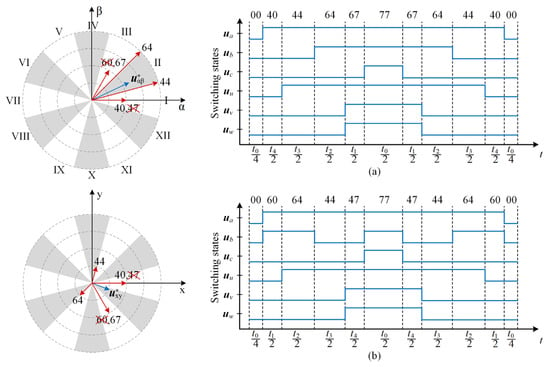
Figure 5.
For Sector II: (a) the center-symmetric switching pattern with a single pulse; (b) the multiple-switching pattern that would result from selecting redundant basic vectors, namely the crossed-out vectors.

Table 3.
The single-pulse switching sequences for each sector.
3.4. Kalman Filter Observer
The accuracy of the prediction model depends on whether the system parameters are precise and whether there are external disturbances. To eliminate the prediction errors caused by these factors, a Kalman filter observer is introduced into the system. The Kalman filter recursively updates the state estimate of the system by minimizing the variance of the estimation error. The observation equation is defined as
where y and e are the vectors of current observation value and total error term. C is the observation matrix, and C = I. The vectors of the total disturbance term e is defined as
The Kalman observer can be designed as
where , P and Q are the predicted state, the predicted estimation error covariance and the process noise covariance. The state estimate can be updated as
where K and R are the Kalman gain and the observation noise covariance.
4. Experimental Validation
4.1. Test Bench
To verify the effectiveness of the proposed multivector DMPC scheme, the design and implementation of the electric drive setup based on a dSPACE MicroLabBox and an asymmetric DTP-PMSM fed by a six-phase 2L-VSI is shown in Figure 6. In addition, an induction motor (IM) is used as the machine load. The key parameters of the used DTP-PMSM and the experiments are listed in Table 4.
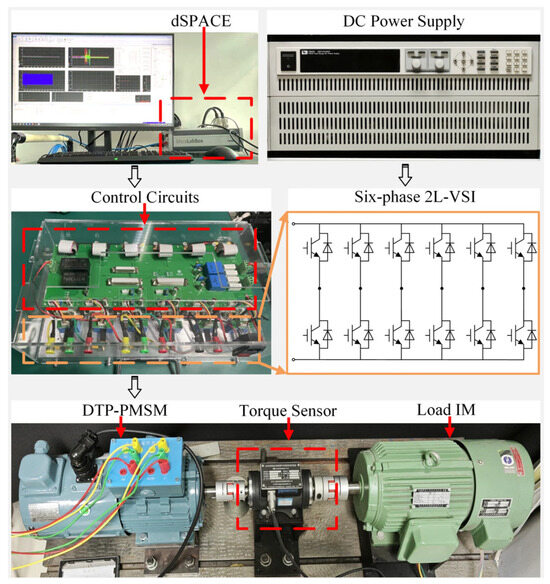
Figure 6.
Experimental test bench of DTP-PMSM control system.

Table 4.
The key parameters of the used DTP-PMSM and the experiments.
4.2. Experimental Results
The motor drag experiments are conducted, considering only the effect of the inner current control loop. To verify the effectiveness of the Kalman filter observer in eliminating errors, experiments are conducted under conditions of magnetic flux or inductance mismatch. The system operates under the proposed multivector DMPC scheme, with a given load motor at 300 rpm and q-current of 6 A. The experiments are performed with magnetic flux φPM at 0.8 times and 1.2 times and dq-inductance L at 0.8 times the nominal values, respectively. As shown in Figure 7, the steady-state error of the q-current is −0.13 A, and the steady-state error of the d-current is 0.1 A when the magnetic flux is 0.8 times. At the same time, the steady-state error of the q-current is 0.15 A, and the steady-state error of the d-current is 0.1 A when the magnetic flux is 1.2 times. The xy-current in both cases has an amplitude of 0.5 A. When the dq-inductance is 0.8 times, the steady-state error of the q-current is −0.1 A, the steady-state error of the d-current is 0.15 A, and the amplitude of the xy-current is 0.7 A. After the observer is enabled, the observer effectively reduces the steady-state error of the dq-current and suppresses the harmonic current in the xy plane to 0.3 A which is caused by the parameter mismatch.
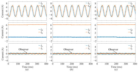
Figure 7.
The observer verification of the proposed multivector DMPC scheme under parameter mismatch: (a) 0.8 φPM, (b) 1.2 φPM, (c) 0.8 L. From top to bottom: phase currents, dq-axis currents, and xy-axis harmonic currents.
To evaluate the control performance of the proposed multivector DMPC scheme, its steady-state and dynamic performance are compared with that of the typical FCS-MPC scheme based on duty-ratio-optimized virtual vectors (FCS-MPC based on DVVs) in [17]. Figure 8 and Figure 9 compare the steady-state performance of the two schemes under two operating conditions: (1) a motor speed of 500 rpm with a rated q-axis current of 8.4 A (corresponding to rated torque), and (2) a motor speed of 1000 rpm with a half-rated q-axis current of 4.2 A (half the rated torque). The experimental waveforms include the six-phase currents, dq-axis currents, and xy-axis harmonic currents.
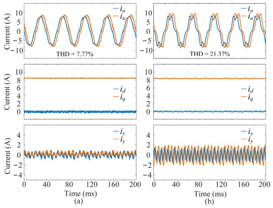
Figure 8.
Steady-state performance results of the two schemes under a motor speed of 500 rpm with a rated q-axis current of 8.4 A: (a) the proposed multivector DMPC scheme, (b) the FCS-MPC based on DVVs. From top to bottom: phase currents, dq-axis currents, and xy-axis harmonic currents.
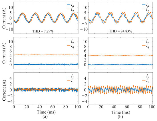
Figure 9.
Steady-state performance results of the two schemes under a motor speed of 1000 rpm with a half-rated q-axis current of 4.2 A: (a) the proposed multivector DMPC scheme, (b) the FCS-MPC based on DVVs. From top to bottom: phase currents, dq-axis currents, and xy-axis harmonic currents.
The comparison results of phase current total harmonic distortion (THD) between the two schemes are summarized in Table 5. Experimental results show that under different operating conditions, the proposed multivector DMPC scheme significantly reduces the phase current THD compared with the FCS-MPC based on DVVs. It effectively suppresses harmonic currents and improves current quality.

Table 5.
Comparison of phase current THD between the two control schemes.
Figure 10 compares the transient performance of the two schemes under a sudden load change at 500 rpm. In the experiments, the load is suddenly reduced, i.e., the reference q-axis current steps down from the rated value of 8.4 A to the half-rated value of 4.2 A. The proposed multivector DMPC scheme achieves a transient response time of 3 ms, which is shorter than the 6 ms response time of the FCS-MPC based on DVVs, demonstrating faster reference tracking. For the proposed multivector DMPC scheme, although the step change in the q-axis reference current causes a noticeable transient ripple in the harmonic currents, its short duration results in minimal impact on the six-phase current quality.
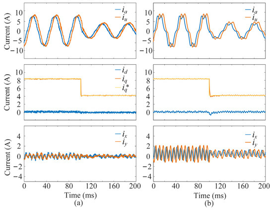
Figure 10.
Transient performance results of the two schemes under a sudden load decrease at 500 rpm: (a) the proposed multivector DMPC scheme, (b) the FCS-MPC based on DVVs. From top to bottom: phase currents, dq-axis currents, and xy-axis harmonic currents.
To verify the effectiveness of the proposed multivector DMPC scheme during the sudden speed change, the experiments are conducted adopting a PI controller to control the outer speed loop. Figure 11 shows the experimental results of a step-up in speed between 300 rpm and 500 rpm with a load of 10 N·m. It can be observed that the proposed multivector DMPC and the FCS-MPC based on DVVs both have a dynamic adjustment time of 0.11 s, while the FCS-MPC based on DVVs has a dynamic adjustment time of 0.15 s. When using the two schemes, the q-current can reach its maximum allowable value more quickly to provide maximum acceleration when the speed changes.
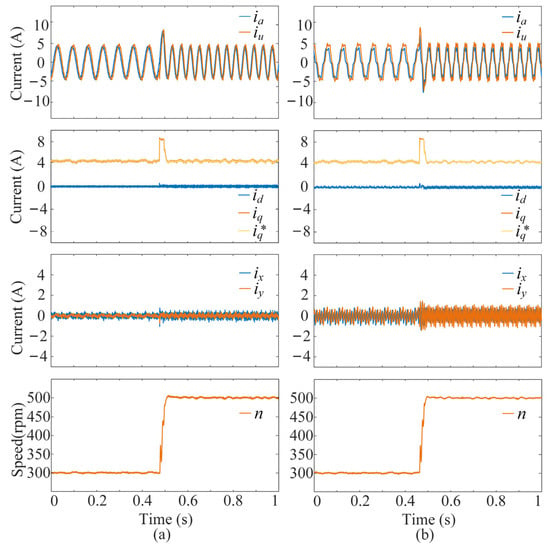
Figure 11.
Transient performance results of the two schemes under a sudden increase in speed with the load of 10 N·m: (a) the proposed multivector DMPC scheme, (b) the FCS-MPC based on DVVs. From top to bottom: phase currents, dq-axis currents, and xy-axis harmonic currents.
To further verify the performance advantages of the proposed multivector DMPC scheme in terms of dynamic response, it is compared with the conventional field-oriented control (FOC) scheme based on proportional–integral (PI) control. A simulation model is built using MATLAB/Simulink 2024b, and the model parameters are set as shown in Table 4. Figure 12 presents the tracking effect of the fundamental current under the condition of sudden load increase, where the reference current of the q-axis jumps from half the rated value to the rated value. The experimental waveforms include the transient phase currents, dq-axis currents, and xy-axis currents when the motor speed is 1000 rpm. Experimental results show that the proposed multivector DMPC scheme tracks the reference current smoothly with a settling time of only 0.7 ms and almost no overshoot. In contrast, the PI-based FOC scheme exhibits poor dynamic tracking performance during sudden load increase, with a settling time of up to 2.1 ms and an overshoot of 23.24%. The reason for this difference is that the bandwidth of the PI control is much lower than that of MPC. In addition, PI control is essentially an error-based control scheme. Its dynamic transition process is characterized by fluctuating oscillation attenuation, resulting in a longer settling time compared with MPC. Meanwhile, the PI-based FOC scheme requires complex parameter tuning, which is avoided by the proposed multivector DMPC scheme.
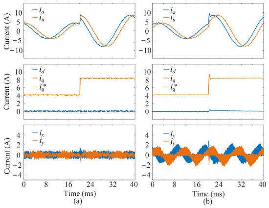
Figure 12.
Transient performance results of the two schemes under a sudden load increase at 1000 rpm: (a) the proposed multivector DMPC scheme, (b) the PI-based FOC scheme. From top to bottom: phase currents, dq-axis currents, and xy-axis harmonic currents.
In summary, the proposed multivector DMPC scheme has excellent harmonic suppression capability and fast dynamic response capability.
5. Conclusions
This paper proposed a multivector DMPC scheme for DTP-PMSM drive systems, enabling closed-loop control in both the fundamental and harmonic planes. First, the proposed multivector DMPC scheme utilizes two large vectors and two basic vectors to perform implicit modulation. It achieves full voltage vector synthesis within the linear modulation region and improved harmonic suppression. Moreover, the optimization problem of fundamental current tracking and harmonic current minimization is formulated as a four-dimensional quadratic programming problem suitable for real-time implementation. The optimal single-pulse switching sequence is directly applied to the t2L-VSI. This is compatible with commonly used microprocessors and avoids equal phase duty-ratio conversion. Furthermore, a Kalman filter observer is integrated into the control system to enhance the robustness of the control scheme by compensating for parameter mismatches and unmodeled disturbances. Experimental validation on a DTP-PMSM drive test bench demonstrates that the proposed multivector DMPC scheme achieves effective harmonic current suppression, improved current quality, reduced torque ripple, and enhanced steady-state and transient performance.
Author Contributions
Conceptualization: B.Q. and R.Y.; Methodology: Y.L., Z.Z. and B.L.; Software: R.Y.; Validation: Z.Z. and B.L.; Formal analysis: B.D.; Investigation: B.D.; Writing—original draft preparation: J.L.; Writing—review and editing: Z.Z. and J.L.; Supervision: L.Y.; Project administration: L.Y.; Funding acquisition: H.W. All authors have read and agreed to the published version of the manuscript.
Funding
This research received no external funding.
Data Availability Statement
The original contributions presented in this study are included in this article. Further inquiries can be directed to the corresponding author.
Acknowledgments
We acknowledge Collaborative lnnovation Research Institute of Ocean Engineering.
Conflicts of Interest
Authors Baoyun Qi, Yu Lu, Jiancheng Liu were employed by the company China Merchants Marine and Offshore Research Institute Co., Ltd. The remaining authors declare that the research was conducted in the absence of any commercial or financial relationships that could be construed as a potential conflict of interest.
References
- Salem, A.; Narimani, M. A Review on Multiphase Drives for Automotive Traction Applications. IEEE Trans. Transp. Electrif. 2019, 5, 1329–1348. [Google Scholar] [CrossRef]
- Liu, A.Z.; Fang, L.; Jiang, D.; Qu, R. A Machine-Learning-Based Fault Diagnosis Method with Adaptive Secondary Sampling for Multiphase Drive Systems. IEEE Trans. Power Electron. 2022, 37, 8767–8772. [Google Scholar] [CrossRef]
- Gu, Y.; Wang, J.; Liang, Z.; Zhang, Z. Mutual-inductance-dynamic-predicted constant current control of LCC-P compensation network for drone wireless in-flight charging. IEEE Trans. Ind. Electron. 2022, 69, 12710–12719. [Google Scholar] [CrossRef]
- Gu, Y.; Wang, J.; Liang, Z.; Zhang, Z. Flexible constant-power range extension of self-oscillating system for wireless in-flight charging of drones. IEEE Trans. Power Electron. 2024, 39, 15342–15355. [Google Scholar] [CrossRef]
- Gu, Y.; Wang, J.; Liang, Z.; Zhang, Z. Communication-free power control algorithm for drone wireless in-flight charging under dual-disturbance of mutual inductance and load. IEEE Trans. Ind. Inform. 2024, 20, 3703–3714. [Google Scholar] [CrossRef]
- Barrero, F.; Duran, M.J. Recent Advances in the Design, Modeling, and Control of Multiphase Machines—Part I. IEEE Trans. Ind. Electron. 2016, 63, 449–458. [Google Scholar] [CrossRef]
- Wang, W.; Liu, C. Modulation Scheme for Five-Phase Electric Machines with Nonlinear Optimization to Improve Voltage Limit Performance. IEEE Trans. Ind. Electron. 2023, 70, 9893–9902. [Google Scholar] [CrossRef]
- Dong, Z.; Liu, Y.; Zhang, B.; Liu, C. Half Open-End Winding Topology Based Nine-Leg VSI for Asymmetrical Six-Phase PMSM Drives. IEEE Trans. Power Electron. 2023, 38, 11399–11410. [Google Scholar] [CrossRef]
- Wang, W.; Liu, C.; Song, Z.; Dong, Z. Harmonic Current Suppression for Dual Three-Phase PMSM Based on Deadbeat Control and Disturbance Observer. IEEE Trans. Ind. Electron. 2023, 70, 3482–3492. [Google Scholar] [CrossRef]
- Vazquez, S.; Rodriguez, J.; Rivera, M.; Franquelo, L.G.; Norambuena, M. Model Predictive Control for Power Converters and Drives: Advances and Trends. IEEE Trans. Ind. Electron. 2017, 64, 935–947. [Google Scholar] [CrossRef]
- Wang, W.; Fan, Y.; Chen, S.; Zhang, Q. Finite control set model predictive current control of a five-phase PMSM with virtual voltage vectors and adaptive control set. CES Trans. Electr. Mach. Syst. 2018, 2, 136–141. [Google Scholar] [CrossRef]
- Davari, S.A.; Khaburi, D.A.; Kennel, R. An Improved FCS–MPC Algorithm for an Induction Motor with an Imposed Optimized Weighting Factor. IEEE Trans. Power Electron. 2012, 27, 1540–1551. [Google Scholar] [CrossRef]
- Zhang, Y.; Yang, H. Model Predictive Torque Control of Induction Motor Drives with Optimal Duty Cycle Control. IEEE Trans. Power Electron. 2014, 29, 6593–6603. [Google Scholar] [CrossRef]
- Zhang, Y.; Yang, H. Generalized Two-Vector-Based Model-Predictive Torque Control of Induction Motor Drives. IEEE Trans. Power Electron. 2015, 30, 3818–3829. [Google Scholar] [CrossRef]
- Kang, S.-W.; Soh, J.-H.; Kim, R.-Y. Symmetrical Three-Vector-Based Model Predictive Control with Deadbeat Solution for IPMSM in Rotating Reference Frame. IEEE Trans. Ind. Electron. 2020, 67, 159–168. [Google Scholar] [CrossRef]
- Gonzalez-Prieto, A.; Martin, C.; González-Prieto, I.; Duran, M.J.; Carrillo-Ríos, J.; Aciego, J.J. Hybrid Multivector FCS–MPC for Six-Phase Electric Drives. IEEE Trans. Power Electron. 2022, 37, 8988–8999. [Google Scholar] [CrossRef]
- Karamanakos, P.; Geyer, T. Guidelines for the Design of Finite Control Set Model Predictive Controllers. IEEE Trans. Power Electron. 2020, 35, 7434–7450. [Google Scholar] [CrossRef]
- Aciego, J.J.; Prieto, I.G.; Duran, M.J. Model Predictive Control of Six-Phase Induction Motor Drives Using Two Virtual Voltage Vectors. IEEE J. Emerg. Sel. Top. Power Electron. 2019, 7, 321–330. [Google Scholar] [CrossRef]
- Aciego, J.J.; Prieto, I.G.; Duran, M.J.; Bermudez, M.; Salas-Biedma, P. Model Predictive Control Based on Dynamic Voltage Vectors for Six-Phase Induction Machines. IEEE J. Emerg. Sel. Top. Power Electron. 2021, 9, 2710–2722. [Google Scholar] [CrossRef]
- Zhang, Z.; Wang, Z.; Wei, X.; Liang, Z.; Kennel, R.; Rodriguez, J. Space-Vector-Optimized Predictive Control for Dual Three-Phase PMSM with Quick Current Response. IEEE Trans. Power Electron. 2022, 37, 4453–4462. [Google Scholar] [CrossRef]
- Li, Z.; Liu, H.A.; Xia, J.; Gao, X.; Rodriguez, J.; Huang, Y.; Liu, Z.; Zhuang, Y.; Zhang, Z. A Novel Virtual Space Vector Modulation-Based Predictive Current Control for Dual Three-Phase Permanent Magnet Synchronous Machine. In Proceedings of the 2025 IEEE International Conference on Predictive Control of Electrical Drives and Power Electronics (PRECEDE), Nanjing, China, 5–8 June 2025; pp. 1–6. [Google Scholar]
- Wu, Y.; Zhang, Z.; Yang, Q.; Tian, W.; Karamanakos, P.; Heldwein, M.L.; Kennel, R. A Direct Model Predictive Control Strategy with an Implicit Modulator for Six-Phase PMSMs. IEEE J. Emerg. Sel. Top. Power Electron. 2023, 11, 1291–1304. [Google Scholar] [CrossRef]
- Yan, L.; Zhang, X.; Yang, J.; Yang, G.; Deng, R. Synthetic Vectors-Based Predictive Control of Dual Three-Phase PMSMs for Current Harmonics Mitigation Considering Average Deception Effect. IEEE J. Emerg. Sel. Top. Power Electron. 2024, 12, 3103–3114. [Google Scholar] [CrossRef]
Disclaimer/Publisher’s Note: The statements, opinions and data contained in all publications are solely those of the individual author(s) and contributor(s) and not of MDPI and/or the editor(s). MDPI and/or the editor(s) disclaim responsibility for any injury to people or property resulting from any ideas, methods, instructions or products referred to in the content. |
© 2025 by the authors. Licensee MDPI, Basel, Switzerland. This article is an open access article distributed under the terms and conditions of the Creative Commons Attribution (CC BY) license (https://creativecommons.org/licenses/by/4.0/).