Abstract
To address the prevalent issues of oscillation and overshoot in high-voltage circuit breaker motor direct-drive mechanisms under classical PI control, this paper proposes an optimized PI speed loop with active damping characteristics. By first establishing a detailed kinematic and dynamic model of the mechanism, we reveal the inherent coupling between tracking performance, disturbance immunity, and the damping ratio within the classical PI speed loop. Our novel method introduces a speed feedback channel at the output of the PI controller to synthesize equivalent viscous damping, thereby enhancing system stability without compromising responsiveness. Through rigorous simulation and experimental validation, the proposed controller’s effectiveness is demonstrated. Compared with the traditional PI controller, the ADPI method reduces the velocity overshoot to only 5.76% in the startup phase, and the maximum velocity tracking error of the velocity is only 18.62% and the cumulative position tracking error is only 0.632 rad under the actual working condition, which is a reduction of 42.7% in the positional error relative to the traditional PI method. The controller also exhibits low sensitivity to changes in the system’s equivalent rotational inertia. This work provides a low-complexity and easy-to-implement speed loop performance enhancement scheme, ideally suited for the short-duration, high-dynamic-load conditions of high-voltage circuit breaker applications.
1. Introduction
Motor direct-drive operating mechanisms, a cutting-edge integration of power electronics, permanent magnet synchronous motors, and servo control technology, offer compelling advantages such as high integration and strong digital control capabilities [1,2,3]. In high-voltage circuit breaker applications, these mechanisms must execute a complete starting–accelerating–braking cycle within an extremely short duration, which imposes strict requirements on the motor’s dynamic response and control accuracy [4,5]. However, due to the intricate composition of diverse mechanical components and the presence of time-varying friction and resistance during operation, the overall dynamic behavior of these mechanisms is highly complex. The significant and rapid changes in load torque and equivalent inertia during the breaker’s operation pose a substantial challenge. Consequently, if a fixed-parameter controller is used, the inevitable mismatch between the controller and the controlled object can severely compromise the mechanism’s stability and anti-interference performance [6,7,8,9]. This issue is particularly critical in direct-drive applications, where the dynamic characteristics of the load change drastically and at a high rate [10].
A considerable body of research has been dedicated to enhancing the rapidity and disturbance immunity of the speed loop by reducing steady-state errors, suppressing overshoots, and shortening recovery times. Ref. [11] proposed an iterative learning calibration scheme, which iteratively corrects inputs based on the deviation between actual and desired outputs. However, the absence of clearly defined convergence conditions for the algorithm makes it challenging to guarantee performance across all operating conditions. Ref. [12] utilized a radial basis function network (RBFN) to adjust PI parameters online, aiming to improve driving performance under various disturbances. Nevertheless, this approach often entails computationally intensive matrix inversions, which can impede control frequency and real-time performance. Yet, the subjective nature of state determination and fuzzy domain division can complicate the design and implementation of smooth parameter switching. Ref. [13] introduced an auto-disturbance controller (ADRC) capable of achieving a fast, overshoot-free, and large-speed step response, though its consistent gain effect over the full speed range remains limited.
In recent years, researchers have focused on more sophisticated adaptive and robust control strategies to address these challenges. For instance, a cascade control system based on an active disturbance rejection controller (ADRC) and a model reference adaptive system (MRAS) was proposed to improve the dynamic performance of PMSMs in electric vehicle applications [14]. Although effective, its application in ultra-fast, high-power systems like circuit breakers may be limited by the computational load of the dual-loop structure. To handle high-inertia loads, a composite control method combining cascaded PI and fuzzy control was investigated to suppress speed oscillations [15]. However, its dependence on accurate fuzzy rule sets can be a design hurdle. Other studies have explored advanced predictive control algorithms, such as the model predictive torque control (MPTC) with an inertia observer, to enhance dynamic response under varying loads [16]. While these methods show promise, the complexity of real-time model prediction and online parameter identification remains a significant bottleneck for the extremely short operation times of direct-drive circuit breakers. Furthermore, a novel control strategy integrating fuzzy logic and an optimal fractional-order PID (FOPID) controller was introduced to improve the robustness of PMSM drives [17], though the tuning of FOPID parameters can be intricate. A robust finite-time position tracking control with a disturbance observer has also been proposed for PMSM systems, offering high precision and rapid response [18]. However, its effectiveness in mitigating time-varying mechanical load disturbances unique to high-voltage breakers requires further validation. For example, a robust finite-time nonlinear speed controller for PMSMs was proposed to reduce speed overshoot to less than 3% and achieve a settling time of approximately 0.15 s, but its applicability to extreme high-speed systems has not been fully explored [19]. To address the complexities of FOPID tuning, a method integrating a genetic algorithm-optimized adaptive fuzzy FOPID was investigated, demonstrating superior speed tracking and robustness against parameter variations [20]. In addition, a low-complexity model predictive control (MPC) strategy was developed to enhance computational efficiency by employing a two-stage filtering strategy, significantly reducing the computational burden from 38 to a maximum of 4 voltage vectors [21].
Despite these efforts, the fast-changing, high-rate load inertia in direct-drive actuators (with operation times as short as 100 ms) poses a significant challenge for real-time parameter identification and online self-tuning [22,23].
To address the oscillation and overshoot issues inherent in classical PI control for high-voltage circuit breaker motor direct-drive mechanisms under strong, time-varying loads, this paper proposes an optimized PI speed loop design incorporating active damping characteristics. First, by taking the motor direct-drive high-voltage breaker as the object, we derive the mapping relationship between the angular displacement of the motor rotor and the vertical travel of the interrupter chamber’s moving end from kinematic and dynamic principles. We then analyze the forces on the main moving parts to establish an equivalent load model. Next, within the framework of transfer functions, we systematically reveal the intrinsic constraints among the tracking performance, disturbance immunity, and damping ratio of a classical PI speed loop. Accordingly, a velocity feedback channel is introduced at the output of the PI controller to synthesize an equivalent viscous damping, thereby improving system damping. This paper also provides a detailed parameter design and robustness analysis. Simulation and prototype experiments demonstrate that compared to a classical PI controller, the proposed method effectively suppresses oscillation and reduces startup overshoot. Furthermore, the system’s speed stability and disturbance immunity under external disturbances are significantly improved.
2. Motor Direct-Drive Operating Mechanism
The motor direct-drive operating mechanism load’s three-dimensional diagram is shown in Figure 1; the load consists of two parts: the drive mechanism and the switch body. The drive mechanism contains the coupling, connecting flange, torsion bar, and brake disk, and the switch body contains overtravel spring, movable contact, static contact, and so on. The switching action is driven by the motor connected with the coupling, from the direction away from the coupling, clockwise for the breaking direction, and counterclockwise for the closing direction. The motor shaft is coaxially connected with the transmission spindle of the high-voltage circuit breaker, and the axis is horizontal and a fixed installation; the crutch arm is rigidly meshed with the transmission spindle, and the two of them do not rotate relative to each other during the whole movement process. The lower end of the insulating rod is hinged to the upper end of the arm through the pin, and the upper end is connected to the bottom of the movable end of the arc-extinguishing chamber. The arc-extinguishing chamber’s moving end consists of moving contacts and their connectors. With the arc-extinguishing chamber closed and vertical structure constraints, its movement in the modeling can be approximated only along the vertical direction of the translation.
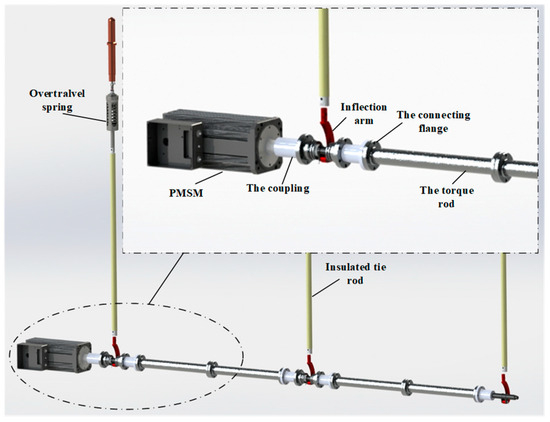
Figure 1.
Three-dimensional model of motor direct-drive operating mechanism.
The motor direct-drive high-voltage circuit breaker studied in this paper uses a permanent magnet synchronous motor (PMSM) to drive a three-phase circuit breaker. In order to ensure the consistency of the three-phase drive, each phase is linked by a torsion bar and rotates synchronously around a common horizontal spindle during operation; this linkage ensures synchronization, but also increases the equivalent load of the drive motor. Since the torsion bar and related components are coaxial with the motor shaft and rotate at the same speed as the rotor, their mass and moment of inertia can be equally divided among the three phases of the respective drive spindles. Based on this equivalence (under the assumption that the three phases are symmetrical and the differences between the phases are negligible), the drive torque of the three-phase device can be modeled as a single-phase modeling: First, find the required torque for the single phase, multiply it by 3, and superimpose the torque required for the movement of the motor rotor to obtain the total motor torque.
By analyzing the kinematics and dynamics of the motor direct drive operating mechanism [24], a load characteristic model can be established:
where
where is the mass of the interrupter; is the acceleration of gravity; is the overtravel spring/contact spring force; is axial component of the insulating rod on the interrupter tension; is the interrupter counterforce and friction; is the bottom of the interrupter vertical motion acceleration, is the tie rod on the spindle arm force in the x-direction component; is the tie rod on the spindle arm force in the y-direction component; and is the rotational inertia of the spindle arm of each part of the rotor shaft equalized in a single-phase value.
The torque in Equation (1) is the variable to be solved, and in a set of prototype motor direct-drive high-voltage circuit breaker systems, all of them are known quantities except for the speed parameter; therefore, it is only necessary to substitute different motor travel curves to obtain the torque demand under different motor travel curves, which further aids the system analysis.
According to the above modeling and analysis, the travel curve in Figure 2 is used as the input signal, and the torque is solved point by point by substituting into Equation (1). The torque jumps near the point of rigor mortis because the overtraveling spring is still in compression before the point of rigor mortis, and the movable end of the interrupter chamber is still in static state. And after the point of rigor mortis, the overtraveling spring is completely released, the movable end of the interrupter chamber begins to move downward, the mass and force of all the moving parts are changed abruptly. Therefore, in this case, if the servo system still adopts fixed controller parameters, it will lead to mismatch between the controller and the controlled object, thus reducing the stability of the operating mechanism and anti-interference performance.
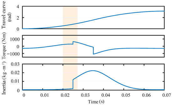
Figure 2.
Simulation calculation.
3. Speed Loop Control Performance of a Classical PI Controller
The servo system’s speed loop mainly includes the current closed loop, servo motor, load and sampling feedback, and other links, mainly used to realize the servo system output speed, and the given command is consistent with the elimination of load disturbances and other factors on the speed of the system rapidity and stability of the impact. The servo system’s speed loop control block diagram is shown in Figure 3, for the speed loop controller. When using the classical PI controller, the speed loop closed loop transfer function is
where and are the proportional and integral gains of the PI controller, is the viscous friction coefficient, and is the moment of inertia. Because the viscous friction coefficient is numerically much smaller than the proportional gain of PI controller under the actual working condition, the viscous friction coefficient is ignored to simplify the subsequent analysis.

Figure 3.
Block diagram of speed loop control.
According to the speed loop control block diagram, the closed-loop transfer function from load torque to speed feedback can be obtained as
In deriving the frequency response of Equation (3) for a DC signal,
From the above equation, when the speed loop uses a classical PI controller, the system has zero steady-state error for a DC signal input. Let the speed reference command be a unit step signal and use the final value theorem to calculate the steady-state value of the tracking error of the speed loop:
From the results, when the speed loop adopts the traditional PI controller, the steady-state error of the speed loop for the reference command is 0 with the step signal.
The selection of speed loop control parameters is closely related to the servo system’s speed loop control performance; commonly used performance indicators include the following: performance and immunity performance. The former mainly includes the rise time, regulation time, and overshoot, etc., and the latter is selected according to the actual working conditions, such as the error integral, the absolute value of the integral of the error times the time, and so on. The rise time can be used to determine the design bandwidth of the speed loop controller:
If it is necessary to set the speed loop rise time not greater than , it is only necessary to make the speed loops and satisfy, respectively,
where is the damping ratio. The requirements of regulation time, overshooting amount, error integral, and other indexes in the performance and anti-disturbance performance mentioned above can be satisfied by adjusting the damping ratio under the above conditions.
Substituting Equations (7) and (8) into Equation (3) yields the closed-loop transfer function of the speed loop as
The characteristic equation of Equation (9) is
where is the speed loop natural frequency.
When , the characteristic Equation (10) has a pair of conjugate poles located in the left half-plane, and there are oscillations and overshoots in the speed loop in the case of a given step signal, and the degree of oscillations is inversely proportional to . Therefore, to improve the following performance of the speed loop, the value of is generally not too small.
For the speed loop immunity performance, the error integral is selected as the evaluation index, set at with sudden load , and the calculation can be obtained as
From the above equation, the error integral of the speed is proportional to . If we want to improve the speed loop immunity performance, we should make the value of as small as possible.
From the above analysis, it can be concluded that under the condition of , when the speed loop is selected from the classical PI controller, it will be difficult to achieve the best of both worlds in the speed loop following performance and immunity performance.
In order to verify the above analytical conclusions, an active damping PI controller is used to simulate and analyze the motor speed response under different values. The motor starts from the stationary state with no load, the set speed is 1700 r/min, a load torque of 2.0 Nm is applied abruptly at 0.5 s, and the speed waveform is shown in Figure 4.
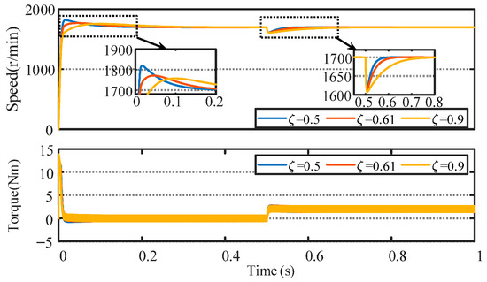
Figure 4.
Comparison of rotational speed response for different damping ratios.
According to Figure 4, the amount of speed overshoot during startup and the adjustment time are positively correlated with the damping ratio. In the case of sudden load application, a higher damping ratio leads to a longer adjustment time, which indicates a decrease in the anti-disturbance performance of the speed loop. At a damping ratio of 0.61, the amount of speed overshoot and the tuning time during startup and disturbance suppression are at a moderate level, showing a relative balance between the tracking and disturbance immunity performance of the speed loop controller. In addition, according to the trend in the figure, when the damping ratio is further increased, the amount of speed drop and the adjustment time when the speed loop encounters a disturbance are expected to continue to increase.
4. Speed Loop Active Damping PI Controller
An active damping-based PI controller is proposed for the motor direct-drive operating mechanism using the classical PI controller as the speed loop controller, as shown in Figure 5, where a speed feedback channel is introduced at the output of the PI controller to obtain

Figure 5.
Active damping PI speed control block diagram.
From Equation (12), it can be seen that the biggest point of difference with the classical PI controller is that the active damping PI controller increases the friction coefficient of the motor, and the speed loop transfer function of the control structure in Figure 5 is
Compared with the proportionality coefficient and friction coefficient of the PI controller, the viscous friction coefficient of the motor is negligible. From the analysis of Equation (9), it can be seen that by adjusting the friction coefficient, the pole distribution of the transfer function can be changed, which in turn adjusts the tracking performance and anti-disturbance performance of the speed loop.
According to the active damping PI speed loop control block diagram, the closed-loop transfer function from load torque to speed feedback can be obtained as
4.1. Speed Loop Active Damping PI Controller Design
From the principle of automatic control, the transfer function of a first-order low-pass filter with cutoff frequency is
Let Equation (13) be equal to Equation (15) and substitute Equation (7) into Equation (8) to obtain
The above equation shows that when the virtual friction coefficient is selected according to the above equation, the speed loop transfer function will be equivalent to the first-order low-pass filter described in Equation (15). The virtual friction coefficient helps reduce the instantaneous speed drop during the sudden speed drop caused by the sudden load increase.
Figure 6 shows the baud plot of the system during the change from to . It can be seen from the figure that the closed-loop bandwidth of the system gradually decreases as increases.
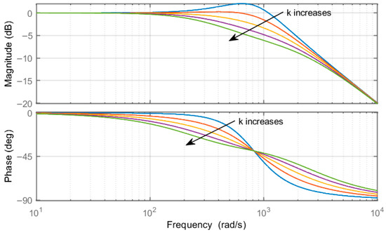
Figure 6.
System baud diagram.
Figure 7 shows the simulated waveforms of speed and torque for different parameter values of . The increase in is favorable to reduce the amount of overshooting as well as shorten the tuning time during startup and perturbation. However, there is a brief spike in the torque during the suppression of the perturbation.
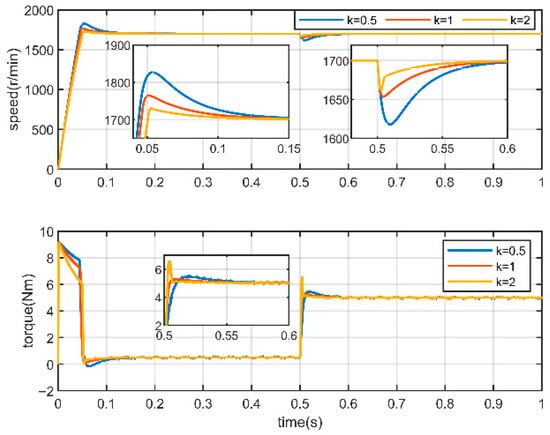
Figure 7.
Comparison of the effects of different k values.
The speed loop performance using a conventional PI controller, a FOPID controller [17], and an actively damped PI controller is comparatively analyzed by simulation, and Figure 8 shows the speed and torque waveforms, with the same simulation setup as previously described. During the startup process, starting from t = 0, both the PI and FOPID methods show a significant amount of overshooting, i.e., the speed exceeds the setpoint before stabilizing, whereas the ADPI shows very little overshooting and achieves a much smoother acceleration process at the cost of a slightly longer tuning time. When the system is perturbed at t = 0.5 s, all three methods react quickly to pull the velocity back to the steady state, and there is no significant difference in the magnitude of the velocity drop. However, ADPI takes slightly longer to recover, the overall difference in adjustment time is not significant compared to PI and FOPID. Thus, the core advantage of the ADPI approach is its ability to significantly reduce overshoot at startup, thus providing smoother control performance, which is especially important in scenarios where precise, overshoot-free startup is required.
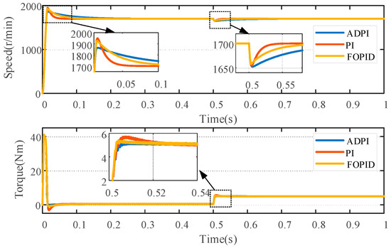
Figure 8.
Speed and torque simulation comparison.
4.2. Controller Robustness Analysis
From the above analysis, the parameters in the design of the speed loop controller still depend on the accuracy of the equivalent moment of inertia of the system, but in the actual working conditions, the equivalent moment of inertia is usually not guaranteed to be maintained unchanged, and thus, it will affect the overall performance of the system to a certain extent.
Assuming that is the nominal value of the equivalent moment of inertia, substituting Equations (7), (8) and (16) into Equation (13) reveals
By setting to increase from to and plotting the change trajectory of the pole position in the above equation, as shown in Figure 9, it can be seen that with the increase in the equivalent inertia , the distance between the pole and the imaginary axis will first increase and then decrease, which corresponds to the stability of the system firstly enhances and then decreases. Therefore, in the case that the equivalent rotational inertia of the system cannot be accurately obtained, the maximum value of the equivalent inertia of the system can be considered for the design of the controller parameters.
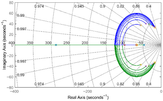
Figure 9.
Changes in speed loop poles during changes in the equivalent moment of inertia J.
5. Experimental Results Analysis
5.1. Anchor Platforms
The experimental study of the control strategy was carried out on a motor rest platform, using the real-time simulation platform as the main control device, and the control and sampling frequency of the system was set to 10 kHz. The pair of rest platforms is shown in Figure 10, the motor is on the left side of the motor to be tested, and its main parameters are shown in Table 1. The middle is the torque measuring instrument, and on the right side is the loaded motor, which is controlled by the system load torque through the programmable control cabinet.
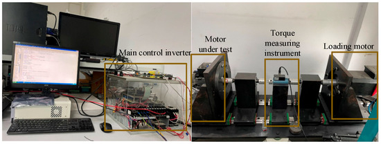
Figure 10.
Experimental platform.

Table 1.
Motor parameters.
Figure 11 and Figure 12 compare the performance of PI, ADPI, and FOPID control methods during motor startup and load disturbance processes. During startup, ADPI demonstrates a significant advantage with a speed overshoot of 5.76%, far outperforming PI and FOPID, indicating that ADPI provides a smoother acceleration process. However, this smoothness comes at the cost of extended settling time, with ADPI taking slightly longer than both PI and FOPID. When the motor system experiences load disturbances, all three methods exhibit speed drops. Specifically, PI shows the smallest speed drop, falling by approximately 11.1%. FOPID follows with a drop to about 1650 r/min, representing a decrease of roughly 2.94%. ADPI exhibited the largest drop, with a decrease of approximately 4.41%. Regarding speed recovery, PI and FOPID demonstrated shorter recovery times, returning to steady state within about 0.2 s. ADPI, however, required a longer adjustment period, taking approximately 0.25 s to achieve basic stability. Overall, the differences in disturbance rejection performance among the three methods were not significant.
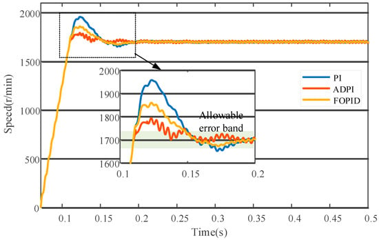
Figure 11.
Speed response during startup.
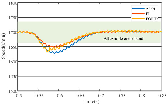
Figure 12.
Speed response under load disturbances.
5.2. Motor Direct-Drive Operating Mechanism Platforms
The experimental platform is a motor direct-drive operating mechanism with a 126 kV circuit breaker, with the circuit breaker parameters described in Table 2 and motor parameters described in Table 3. And the controller and the motor adopted a split design, as shown in Figure 13, with the controller in the middle layer of the control cabinet and the energy storage capacitor in the lowest layer. The main board of the controller adopted the dual-core architecture of CPLD and DSP, and its system control frequency and sampling frequency ewre set to 10 kHz. The system state information was saved in real time in the controller’s RAM chip for the host computer to read and analyze.

Table 2.
Characteristic parameters of circuit breaker.

Table 3.
Drive motor parameters.
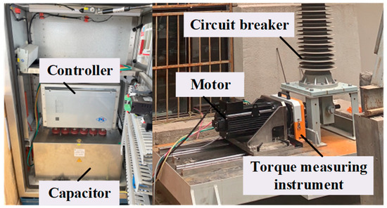
Figure 13.
Prototype platform.
In terms of speed and position tracking, the dynamic response of the classical PI control exhibits significant overshoot and oscillation. As shown in Figure 14, the speed waveform exhibits pronounced overshoot during startup, with a maximum tracking error reaching 32.5%, accompanied by persistent oscillations throughout the entire operation. In contrast, the ADPI control strategy in Figure 15 achieves a smoother response, featuring minimal speed overshoot, a maximum tracking error of 18.62%, and exceptional stability maintained throughout the entire stroke. This enhanced speed control directly translates to superior position tracking. The ADPI strategy achieves tighter and more accurate position tracking, with a cumulative tracking error of only 0.632 rad. In contrast, the PI strategy exhibits a cumulative tracking error of 1.278 rad. Under PI control, the current waveform exhibits significant fluctuations; conversely, the current waveform under ADPI control is exceptionally smooth, with markedly reduced current variations. This demonstrates ADPI’s superior precision and stability in motor torque control. Experimental data confirms ADPI’s outstanding performance in practical applications across multiple dimensions. It not only delivers more stable and accurate dynamic responses but also effectively improves current waveform quality, thereby enhancing the overall control performance of the system.
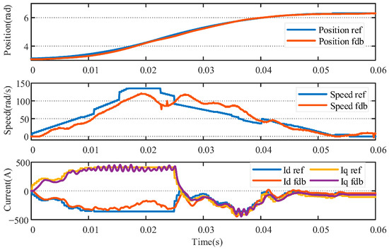
Figure 14.
The breaking process of the classical PI controller.
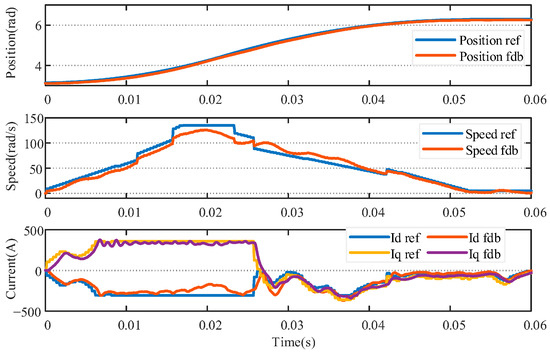
Figure 15.
The breaking process with active damping PI control.
6. Conclusions
This paper presents a novel actively damped PI controller designed to optimize the speed loop of a high-voltage circuit breaker’s motor direct-drive mechanism. The proposed actively damped PI controller significantly improves the dynamic performance of the high-voltage circuit breaker’s motor direct-drive mechanism by introducing equivalent viscous damping in the velocity loop. During the startup phase, the ADPI controller exhibits excellent overshoot rejection compared to the conventional PI and FOPID methods, with a velocity overshoot of only 5.76%, which is much lower than the other two methods, ensuring a smooth acceleration process. Despite the slight increase in the anti-disturbance recovery time, ADPI still has a slight advantage in the speed drop amplitude. The superiority of ADPI is further confirmed by the quantitative analysis of the experimental waveforms: its maximum speed tracking error is only 18.62%, which is much lower than that of PI’s 32.5%; the cumulative error of position tracking is only 0.632 rad, which is half that of the PI strategy. In addition, the current waveform under ADPI control is exceptionally smooth and the fluctuation is significantly reduced, indicating that its control of motor torque is more accurate and stable. In combining the simulation and experimental results, the method effectively improves the stability and accuracy of the system without significantly sacrificing the response speed, and especially shows significant advantages in the overshoot suppression and tracking performance.
The findings of this study carry significant implications for the design and operation of high-voltage circuit breakers. The effective suppression of speed overshoot directly translates to a reduction in mechanical stress and impact on the operating mechanism, which enhances the system’s overall reliability and can extend its operational lifespan. The improved disturbance immunity ensures robust performance under real-world conditions where load and friction are highly time-varying.
While this study successfully validates the proposed method under key operating conditions, future work can build upon these findings. Further research could explore the controller’s performance under a wider range of operating temperatures and different mechanical load types. A more in-depth comparative analysis with other advanced control algorithms, such as those based on online identification or disturbance observers, could provide a broader benchmark and highlight the unique benefits of our method’s balance between simplicity and performance.
Author Contributions
Conceptualization, X.W. (Xiao Wang); Writing—original draft, X.W. (Xiao Wang); Resources, X.W. (Xusheng Wu); Writing—review & editing, X.X.; Project administration, X.X. All authors have read and agreed to the published version of the manuscript.
Funding
This research received no external funding.
Data Availability Statement
The original contributions presented in this study are included in the article. Further inquiries can be directed to the corresponding author.
Conflicts of Interest
The authors declare no conflict of interest.
References
- Lin, X.; Zhang, H.; Li, Y.; Xu, J. Research on mechanical characteristics monitoring system for high-voltage circuit breaker motor operating mechanism. In Proceedings of the 2011 International Conference on Electrical Machines and Systems, Beijing, China, 20–23 August 2011; pp. 1–4. [Google Scholar]
- Bosma, A.; Thureson, P.-O. A new reliable operating mechanism for HVAC circuit-breakers. In Proceedings of the 2001 IEEE/PES Transmission and Distribution Conference and Exposition. Developing New Perspectives (Cat. No.01CH37294), Atlanta, GA, USA, 2 November 2001; Volume 1, pp. 573–577. [Google Scholar]
- Stanek, M. Analysis of circuit breaker controlled switching operations—From manual to automatic. In Proceedings of the 2015 50th International Universities Power Engineering Conference (UPEC), Stoke on Trent, UK, 1–4 September 2015; pp. 1–6. [Google Scholar]
- Zheng, S.; Tang, X.; Song, B.; Lu, S.; Ye, B. Stable adaptive PI control for permanent magnet synchronous motor drive based on improved JITL technique. ISA Trans. 2013, 52, 539–549. [Google Scholar] [CrossRef] [PubMed]
- Springob, L.; Holtz, J. High-bandwidth current control for torque-ripple compensation in PM synchronous machines. IEEE Trans. Ind. Electron. 1998, 45, 713–721. [Google Scholar] [CrossRef]
- Khatounian, F.; Moreau, S.; Monmasson, E.; Janot, A.; Louveau, F. Parameters Estimation of the Actuator used in Haptic Interfaces: Comparison of two Identification Methods. In Proceedings of the 2006 IEEE International Symposium on Industrial Electronics, Montreal, QC, Canada, 9–13 July 2006; Volume 1, pp. 211–216. [Google Scholar]
- Xing, Q.; Wang, T.; Huang, S. On-line Identification of Equivalent Inertia for DFIG Wind Turbines Based on Extended Kalman Filters. In Proceedings of the 2021 IEEE/IAS Industrial and Commercial Power System Asia (I&CPS Asia), Chengdu, China, 18–21 July 2021; pp. 834–839. [Google Scholar]
- Yadav, D.; Verma, A. Performance analysis of permanent magnet synchronous motor drive using Particle Swarm Optimization technique. In Proceedings of the 2016 International Conference on Emerging Trends in Electrical Electronics & Sustainable Energy Systems (ICETEESES), Sultanpur, India, 11–12 March 2016; pp. 280–285. [Google Scholar]
- Uddin, M.N.; Abido, M.A.; Rahman, M.A. Development and implementation of a hybrid intelligent controller for interior permanent magnet synchronous motor drive. In Proceedings of the Conference Record of the 2002 IEEE Industry Applications Conference. 37th IAS Annual Meeting (Cat. No.02CH37344), Pittsburgh, PA, USA, 13–18 October 2002; Volume 2, pp. 1439–1446. [Google Scholar]
- Yan, H.; Lin, X.; Xu, J.; Tang, T.; Tang, D.; Bao, Y. Design of Motor Mechanism of 126kV High Voltage Circuit Breaker and Control Strategy of Stroke Subsection. In Proceedings of the 2019 IEEE International Conference on Mechatronics and Automation (ICMA), Tianjin, China, 4–7 August 2019; pp. 610–614. [Google Scholar]
- Li, Z.; Xiao, D.; He, S. Self tuning PID controller based on fuzzy inference. Control. Theory Appl. 1997, 2, 238–243. [Google Scholar]
- Rahman, M.A.; Uddin, M.N.; Abido, M.A. An artificial neural network for online tuning of genetic algorithm based PI controller for interior permanent magnet synchronous motor drive. In Proceedings of the Power Conversion Conference-Osaka 2002 (Cat. No.02TH8579), Osaka, Japan, 2–5 April 2002; Volume 1, pp. 154–160. [Google Scholar]
- Zhang, J.; Chen, Y.; Gao, Y.; Wang, Z.; Peng, G. Cascade ADRC Speed Control Base on FCS-MPC for Permanent Magnet Synchronous Motor. J. Circuit. Syst. Comp. 2021, 30, 2150202. [Google Scholar] [CrossRef]
- Upadhyaya, A.; Gaur, P. Speed Control of Hybrid Electric Vehicle using cascade control of Fractional order PI and PD controllers tuned by PSO. In Proceedings of the 2021 IEEE 18th India Council International Conference (INDICON), Guwahati, India, 19–21 December 2021; pp. 1–6. [Google Scholar]
- Öztürk, N.; Çelik, E. Speed control of permanent magnet synchronous motors using fuzzy controller based on genetic algorithms. Int. J. Electr. Power Energy Syst. 2012, 43, 889–898. [Google Scholar] [CrossRef]
- Sun, X.; Wu, M.; Yin, C.; Wang, S. Model Predictive Thrust Force Control for Linear Motor Actuator used in Active Suspension. IEEE Trans. Energy Convers. 2021, 36, 3063–3072. [Google Scholar] [CrossRef]
- George, M.A.; Kamat, D.V.; Kurian, C.P. Electronically Tunable ACO Based Fuzzy FOPID Controller for Effective Speed Control of Electric Vehicle. IEEE Access 2021, 9, 73392–73412. [Google Scholar] [CrossRef]
- Hassani, H.; Mansouri, A.; Ahaitouf, A. Robust Finite-Time Tracking Control Based on Disturbance Observer for an Uncertain Quadrotor under External Disturbances. J. Robot. 2022, 2022, 4581165. [Google Scholar] [CrossRef]
- Li, J.; Ren, H.-P.; Zhong, Y.-R. Robust Speed Control of Induction Motor Drives Using First-Order Auto-Disturbance Rejection Controllers. IEEE Trans. Ind. Appl. 2015, 51, 712–720. [Google Scholar] [CrossRef]
- Shalaby, R.; El-Hossainy, M.; Abo-Zalam, B.; Mahmoud, T.A. Optimal fractional-order PID controller based on fractional-order actor-critic algorithm. Neural Comput. Appl. 2023, 35, 2347–2380. [Google Scholar] [CrossRef]
- Hu, J.; Fu, Z.; Xu, R.; Jin, T.; Feng, Z.; Wang, S. Low-Complexity Model Predictive Control for Series-Winding PMSM with Extended Voltage Vectors. Electronics 2025, 14, 127. [Google Scholar] [CrossRef]
- Wang, X.; Guo, Y.; Xiao, X.; Huang, Y.; Deng, Y.; Liu, Q. Research on Direct Drive Operation Mechanism of 126 kV High-voltage Vacuum Circuit Breaker. In Proceedings of the 2019 22nd International Conference on Electrical Machines and Systems (ICEMS), Harbin, China, 11–14 August 2019; pp. 1–5. [Google Scholar]
- Deng, Y.; Fan, N.; Yang, H.; Huang, Y. Research on Technology of 126 kV Motor Drive Vacuum Circuit Breaker. In Proceedings of the 10th International Conference on Power Electronics, Machines and Drives (PEMD 2020), Online Conference, 15–17 December 2020; Volume 2020, pp. 776–781. [Google Scholar]
- Wang, X.; Wu, X.; Xiao, X.; Xie, Y. A Polynomial Model and Multi-Objective Optimization Based Travel Curve Planning Method for Direct Motor Drive Actuators. IEEE Access 2023, 11, 69773–69782. [Google Scholar] [CrossRef]
Disclaimer/Publisher’s Note: The statements, opinions and data contained in all publications are solely those of the individual author(s) and contributor(s) and not of MDPI and/or the editor(s). MDPI and/or the editor(s) disclaim responsibility for any injury to people or property resulting from any ideas, methods, instructions or products referred to in the content. |
© 2025 by the authors. Licensee MDPI, Basel, Switzerland. This article is an open access article distributed under the terms and conditions of the Creative Commons Attribution (CC BY) license (https://creativecommons.org/licenses/by/4.0/).