Abstract
The reliability of the generator circuit breaker (GCB) switching coil affects the safe and stable operation of the power system, in which the faults of abnormal voltage, poor contact, and mechanical jamming of the switching coil can easily lead to the refusal of the circuit breaker, which threatens the safety of the power grid. In order to study the fault characteristics of the GCB switching coil, this paper combines multi-physical field simulation and experimental testing, establishes the electromagnetic field simulation model of the switching coil, and analyzes the characteristics of current waveforms under typical faults such as voltage abnormality, poor contact, and core jamming. Through simulation and testing to verify the mechanism of current waveform distortion under different fault states, demonstrated the change rule of characteristic parameters when the fault occurs, and provided a basis for the diagnosis of the operation status of the switching coil based on current waveform.
1. Introduction
The generator circuit breaker (GCB) is a generator set and the main transformer between the key protection equipment; its reliable operation for the stability of the power system is critical. The composition of the GCB, in addition to the important primary electrical components and actuators, also includes a large number of secondary components for control, monitoring, protection, and other functions, such as switching coils and various types of relays. In addition to the important primary electrical components and the actuator, the GCB also includes a large number of secondary components for control, monitoring, protection, and other functions, such as switching coils and various types of relays. Among them, the switching coil is the key component of the actuator, and its performance directly affects the reliability of the circuit breaker operation. Under the severe working conditions of high heat, high humidity, vibration, dust, and electromagnetic interference at the operation site, the switching coil is affected by many factors, such as the harsh electromagnetic environment, the harsh outdoor atmospheric environment, action mechanical stress, etc., and its contacts will be oxidized or ablated after long-term operation, which will lead to changes in action voltage, action time, and contact resistance of the contacts, and thus result in unreliable action, which will seriously affect the reliability of the switching coil.
The state of the switching coil determines the reliability of the mechanical actuating system, and the mechanical failure of the circuit breaker can be effectively detected by conducting the mechanical characteristic test of the circuit breaker and analyzing the current signal of the switching coil [1]. However, it is often difficult to detect insulation defects in the manufacturing process of the coil by conventional test methods. These potential defects will gradually develop under the action of alternating electromagnetic fields during long-term operation, which may ultimately lead to local overheating or turn-to-turn short-circuiting, resulting in a decrease in magnetic potential and an abnormal increase in current, etc. In severe cases, the GCB cannot complete the opening and closing operations normally, and even the coil heats up due to the prolonged energization. Even the coil will be heated up due to the long-time power supply, leading to a serious fault of the GCB refusing to operate.
Previous research on fault diagnosis for switching coils has extensively explored various signal types, both domestically and internationally [2]. For instance, studies have utilized vibration signals [3] and acoustic signals to monitor mechanical conditions. Acoustic signal-based methods, as demonstrated in research analyzing sound patterns to identify faults in high-voltage circuit breakers, offer non-invasive detection but are often susceptible to environmental noise and interference, limiting their accuracy in noisy operational sites [4]. In contrast, current signal analysis has gained prominence due to its inherent advantages: it provides high accuracy in capturing electrical characteristics (e.g., current magnitude and waveform anomalies), exhibits strong resistance to external disturbances such as electromagnetic interference and vibration, and enables real-time monitoring without significant signal degradation. These benefits make current signals particularly suitable for diagnosing faults under the harsh conditions typical of GCB operations, as evidenced by studies focusing on feature extraction and fault discrimination using coil current data [5]. Therefore, building on these insights, this paper selects current signal analysis as the primary method for fault diagnosis, leveraging its robustness to enhance detection reliability.
This paper establishes an electromagnetic field simulation model of the GCB breaking coil and develops a fault simulation platform to systematically investigate three typical faults—abnormal circuit voltage, poor contact, and core jamming—by analyzing their characteristic current signatures. The strong consistency achieved between simulation and experimental results validates the model’s accuracy, while the identified current patterns provide a practical foundation for developing non-intrusive online monitoring systems to enhance power system reliability.
2. Failure Simulation of Switching Coil Performance Simulation
2.1. Principle of the Generator Circuit Breaker Switching Coil Action
Based on the systematic analysis of the GCB breaking and closing action mechanism, the execution of the breaking and closing action originates from the excitation process of the breaking and switching coil [6]; the moving iron core starts to move under the action of magnetic force and controls the high- and low-pressure circuits of the hydraulic system to achieve the breaking and closing operation of the GCB, so the normal operation of the breaking and switching coil is a powerful guarantee for the action characteristics and reliability of the GCB [7].
During the opening and closing process of the GCB, the current signal of the opening and switching coil contains rich state information: on the one hand, it reflects the mechanical state of the actuator body, and on the other hand, it also characterizes the electrical characteristics of the coil itself, and a variety of fault characteristics can be extracted from the current waveform, such as abnormal voltage of the coil circuit, poor contact of the circuit, and faults of the core jamming, etc. [8]. A typical switching coil current waveform is shown in Figure 1.
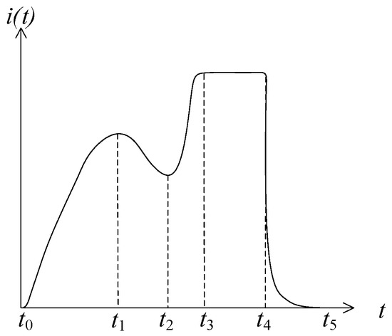
Figure 1.
Schematic diagram of typical switching coil current waveforms.
The GCB switching coil can be equivalent to an ideal inductive coil and resistance, and its switching control equivalent circuit is shown in Figure 2, where U is the control power supply, S is the control switch, i is the current in the line when S is on, R is the resistance, and L is the coil inductance. Besides, the voltage applied to the coil is continuous [9].
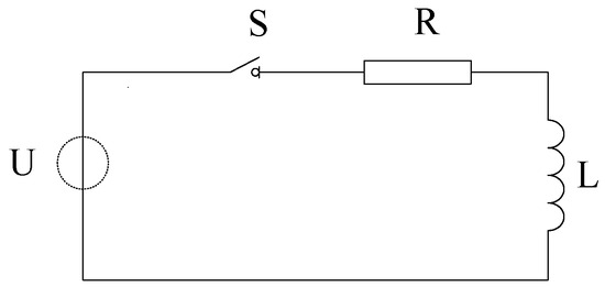
Figure 2.
Equivalent circuit of high-voltage circuit breaker switching coil.
The change in the switching coil current over time is expressed by the differential Equation (1):
U, i, R, L(x) in Equation (1) are the voltage, current, resistance, and inductance, respectively. Taking the derivative with respect to time yields Equation (2), which shows that when the voltage is constant, the current primarily varies with changes in the core’s velocity v.
v is the speed of motion of the iron core.
D’Alembert’s equation of motion is given in Equation (3):
In Equation (3), F, Ff are the electromagnetic suction force and reaction force (reset spring elasticity, gravity, and friction) on the moving core; m is the total mass of the moving object (moving core and push rod); and x, t are the displacement and movement time of the core, respectively.
The process of current change in the switching coil can be divided into five stages [10]:
- (1)
- The stationary stage of the moving core (t0~t1): When the coil circuit is energized, due to the presence of inductance, the circuit current does not immediately reach a steady state. Instead, it gradually increases from zero to a stable value, following an exponential growth pattern described by Equation (4), corresponding to the t0–t1 interval in Figure 1. The magnetic force exerted by the coil core also progressively increases. Upon reaching t1, the electromagnet’s magnetic force gradually overcomes its resistance, causing the electromagnet to activate.
- (2)
- The moving core motion stage (t1~t2): After time t1, the electromagnetic force generated by the coil drives the core to move, causing its velocity to increase rapidly. In the equivalent circuit, a gradually increasing counter-electromotive force appears. At this point, the circuit current i for closing and opening the switch is less than the initial operating current. The continuously increasing trend changes direction and begins to decrease, corresponding to the interval t1–t2 in Figure 1. When the electromagnet strikes the latch, the core stops moving.
- (3)
- Stable maintenance stage (t2~t3): after the moving core moves to the limit position, the current continues to grow exponentially, and ultimately tends to a steady state value;
- (4)
- Steady state operation stage (t3~t4): the current maintains a constant;
- (5)
- Power-off reset stage (t4~t5): after the control loop is disconnected, the energy storage element releases the energy, and the current rapidly decays to zero.
2.2. Model Establishment and Simulation Parameter Setting
In this study, the current characteristics of the circuit breaker switching coil under normal operating conditions are first modeled, simulated, and analyzed based on COMSOL Multiphysics 6.2. On this basis, a variety of switching coil fault simulation experiments are designed to simulate three kinds of faults, such as coil circuit voltage abnormality, poor contact, core jamming, etc., by modifying the control voltage, coil resistance, core quality, etc., to obtain the switching coil current under different fault states, compare the switching coil current waveforms of the circuit breaker’s normal state and the typical fault state, and obtain the rule of the change of coil current. Based on the change rule of coil current, it can make a judgment on the state of the braking coil and locate the faults.
2.2.1. Establishment of the Switching Coil Model
The switching coil consists of a moving core, a static core, a coil, a reset spring, and other components, and the 3D model diagram is shown in Figure 3a. This simulation assumes that the switching coil is uniformly distributed in the winding [11]. Due to the need for multiple simulations of the circuit breaker’s normal operating state and various types of fault states of the switching coil current data, the comprehensive consideration of computational efficiency and simulation time, without sacrificing the quality of the simulation under the premise of shortening the calculation time as much as possible, and the use of COMSOL two-dimensional axisymmetric structure to establish the model of the switching coil, such as shown in Figure 3b for the structure of the GCB 1/2 switching coil schematic. The geometry of the switching coil assembly is predominantly axisymmetric. Although a 3D model could capture more spatial details (e.g., minor asymmetries, intricate spring geometry), a 2D axisymmetric model was employed in this study to achieve an optimal balance between computational efficiency and simulation accuracy for the electromagnetic fields and core motion. This simplification is justified, as the primary objective was to capture the overall coil current waveform and its characteristic changes under fault conditions, which are the key indicators for fault diagnosis. The COMSOL software in the simulation of the three-dimensional model of the spring winding is not a good idea, but it is a good idea. COMSOL software in the simulation will be an axisymmetric mirror image after the simulation calculation.
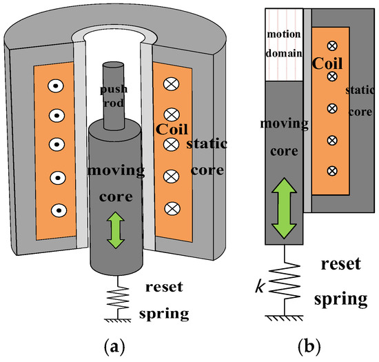
Figure 3.
(a) Three-dimensional model diagram of GCB switching coil; (b) 2D axisymmetric diagram of GCB switching coil.
2.2.2. Model Parameters and Material Settings
The model of the switching coil mainly includes the moving and static cores, the coil, and the moving domain of the moving core, which is moved by the electromagnetic force. Before simulation, the model needs to be meshed and the materials set. Grid division will affect the simulation speed and accuracy of the simulation results; too large a grid will lead to simulation results that are not accurate enough, and too small a grid will lead to the simulation of a computational volume that is too large. Model components of the material settings will affect the simulation process of the interaction of the electric field and the magnetic field. The meshing accuracy of each component in the switching coil model is shown in Table 1.

Table 1.
Mesh division of switching coil model.
The material settings of the simulation model components and motion domains are shown in Figure 3, in which the materials of the dynamic and static cores, coils, and motion domains are all directly selected from the COMSOL material library; the material of the dynamic and static cores is Soft Iron, the material of the coils is Copper, and the material of the motion domains is Air, which is the same as that of the actual material of the GCB tap changer coil. The basic parameters of the switching coil model is shown in Table 2.

Table 2.
Basic parameters of the switching coil model.
2.2.3. Simulation Parameter Settings
The dynamic mesh module, magnetic field (mf) module, and global ordinary differential and differential algebraic equation (ge) module of COMSOL are used in this simulation. Since the motion process of the moving core is time-dependent, in order to obtain the variation of the coil current of the switching coil during the motion process of the moving core, the transient study should be selected for this simulation model.
The voltage of the switching coil under normal conditions is 220 V, and the resistance of the coil is 154 Ω. In order to simulate the opening and closing performance of the switching coil, the coil excitation is set to be a voltage in the simulation model, and the pulse wave power supply is selected for the voltage excitation.
2.3. Simulation Results
In the COMSOL software simulation, the normal operating state of the opening and switching coil current waveform is obtained, as shown in Figure 4.
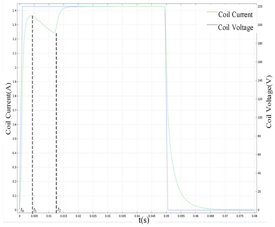
Figure 4.
Normal switching coil current waveforms.
From Figure 4, it can be seen that the switching coil is energized at time 0; due to the inductance of the coil, the current i starts to increase gradually from 0 to an exponential law, and at the same time, the electromagnetic force received by the movable iron core does not reach the value of the movement of the movable iron core, and the movable iron core remains static; with the increase in the coil current, the coil current appears to be the first peak at the time of t1, and the movable iron core starts to move and generates the counteracting potential, and the coil current gradually decreases. Gradually decrease; in t2 time, the moving core moves to the maximum stroke, corresponding to the coil current waveform of the valley position, the movement of the reaction potential disappears, and the current continues to increase to the steady-state current value according to the exponential law. At 50 ms, the DC voltage source of the driving circuit is disconnected, the coil current goes to zero, the moving core is reset under the action of the reset spring elasticity and its own gravity, and the current gradually decreases to 0. The COMSOL simulation results are in line with the analysis results of the switching coil current in Section 2.1, which verifies the correctness and reliability of the simulation results from the perspective of mechanistic analysis.
2.4. Switching Coil Fault Simulation
In order to investigate the impact of circuit breaker defects on the switching coil current, and according to the actual operation and maintenance of the GCB and the switching coil faults, this paper simulates three kinds of defective states of the switching coil of the GCB: voltage abnormality, poor circuit contact, and core jamming.
2.4.1. Abnormal Voltage Fault Simulation
An abnormal voltage fault belongs to the control circuit fault of the switching coil, which can be simulated by changing the DC voltage of the driving circuit in the control circuit. Taking the case of voltage reduction as an example, the change of the switching coil current waveform under this condition is shown in Figure 5, which is the comparison of the switching coil current waveforms when the power supply voltage of the driving circuit is 220 V (normal condition), 210 V, and 200 V, respectively.
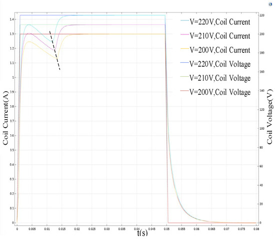
Figure 5.
Coil current waveform changes during abnormal voltage faults.
When the DC voltage is reduced, the current through the switching coil is reduced, and the electromagnetic force on the moving core is reduced, resulting in a reduction in the speed of the moving core and an increase in the time required for the core to reach the maximum stroke, which corresponds to the dashed line marking the valley position shifted to the right in the figure, and the size of the coil current will change when the current in the switching coil reaches the steady state. In the steady state, the coil can be regarded as a wire, the size of the current through the switching coil only, and the voltage and resistance of the drive circuit are related to the voltage formula I = U/R, which can be seen; the size of the steady-state current value is proportional to the coil voltage.
2.4.2. Poor Contact Fault Simulation
Poor contact faults in the switching coil control circuit refer to the aging of the coil contacts or poor contact between the contacts and the driving circuit, and this kind of fault will lead to an increase in the coil resistance. These two situations can be simulated by increasing the coil resistance. As shown in Figure 6, it is the comparison of the coil current waveforms when the coil resistance is 154 Ω (normal condition), 164 Ω, and 174 Ω, respectively.
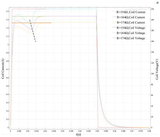
Figure 6.
Coil current waveform variation during poor contact failure.
As indicated by the dashed line in Figure 6, similar to the abnormal voltage failure, the increase in coil resistance will reduce the current passing through the switching coil, which in turn affects the reduction of the size of the electromagnetic force on the core, leading to a reduction in the speed of the moving core, which ultimately leads to an increase in the time for the core to reach the maximum movement stroke and a reduction in the current when reaching steady state. The underlying mechanism involves several interconnected physical processes.
The increased circuit resistance reduces the initial current surge according to Ohm’s Law (I = V/R), with the 6.5% resistance increase (164 Ω vs. 154 Ω) resulting in a proportional current decrease. This diminished current produces a quadratic reduction in electromagnetic force, as Fem ∝ I2, following the fundamental relationship Fem = (NI)2μ0A/(2g2).
Fem: Electromagnetic force developed by the coil (Newtons, N). This is the force that actuates the moving core.
N: Number of turns in the switching coil (dimensionless). A design constant.
μ0: Permeability of free space (4π × 10−7 N/A2). A physical constant.
A: Cross-sectional area of the magnetic circuit (square meters, m2). A design constant related to the core geometry.
g: Air gap length between the moving and static cores (meters, m). This decreases as the core moves.
The reduced electromagnetic force directly impacts the core dynamics through Newton’s second law: m(d2x/dt2) = Fem − Fspring − Ffriction. The lower acceleration (d2x/dt2) significantly increases the time required to reach both the activation threshold and maximum stroke. Additionally, the increased resistance enhances Joule heating (Ploss = I2R), which can further deteriorate contact surfaces and create a positive feedback loop that exacerbates the fault condition.
The steady-state current reduction follows Iss = V/R, but the transient response provides more diagnostic information. The delayed current peak and prolonged transition time reflect the impaired energy conversion efficiency from electrical to mechanical domains. The time-integrated electromagnetic work (W = ∫Fem dx) shows that increased resistance reduces the total mechanical energy available for proper operation, potentially leading to incomplete closing or opening operations.
This analysis demonstrates how resistance increase affects the complete electromechanical response and provides deeper insight into the fault mechanisms for improved diagnostic capabilities.
2.4.3. Iron Core Jamming Fault Simulation
Due to the aging or corrosion of the core components, eccentricity, resulting in the movement of the moving core, is blocked; the fault can be simulated by increasing the mass of the moving core. The following is a comparison of the current waveforms of the closing and opening coils when the mass of the moving core is 10 g (normal condition), 15 g, and 20 g, respectively.
The 50% mass increase (from 10 g to 15 g) has two significant effects. First, it increases the gravitational component (m · g) in the opposition forces, requiring a larger electromagnetic force to initiate movement. This explains the delayed start of movement evident in the rightward shift of the current waveform’s first peak. Therefore, as the mass of the moving core increases, the time for the first peak of the coil current waveform to reach the first peak is shifted back, and the time for the core to reach the maximum movement distance is also shifted back. As indicated by the dashed line in Figure 7. This is due to the increase in the mass of the moving iron core. On the one hand, it will lead to an increase in the gravity of the moving iron core; the electromagnetic force required for the moving iron core to overcome the reaction force to start the movement will increase accordingly, and the time for the moving iron core to start the movement will be delayed. On the other hand, in the case of the constant combined force of the moving iron core, the increase in the mass of the moving iron core will lead to a decrease in the acceleration of the movement.
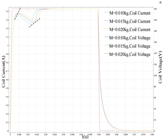
Figure 7.
Coil current waveform variation during core jamming faults.
3. Failure Simulation Test of Switching Coil Performance
In order to verify the accuracy of the simulation results, this paper builds a fault simulation platform to simulate the three defective states of the GCB switching coil and collects coil current curves of the circuit breaker in the case of abnormal switching coil circuit voltage, poor circuit contact, and core jamming.
3.1. Test Platform
This test simulates the typical defective state of the GCBs switching coil and builds the test platform as shown in Figure 8. The fault simulation test platform consists of four main components: Circuit breaker motion characteristic analyzer (model: DB-8002); Circuit breaker switching coil (rated voltage: 220 V DC, resistance: 154 Ω); Custom-designed resistance board (adjustable range: 0–100 Ω); Weight set for core mass adjustment (100 g, 300 g, and 500 g weights with ±0.1 g accuracy). The sample switching coil is shown in Figure 9. The coil current curves of the GCB under typical fault conditions such as abnormal return voltage of the breaking coil, poor circuit contact, core jamming, etc., are collected, and the coil current waveforms under the normal and typical fault conditions are compared so as to establish the relationship between the type of defective faults, the degree of severity, and the variation rate of the current curves, and to make a judgement on the circuit breaker status and fault location based on the variation rate of the characteristic parameters [12,13,14,15,16]. To ensure the reliability and repeatability of the experimental data, each test condition was repeated five times. The representative waveform presented in the figures below is the average of these five trials.
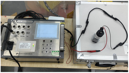
Figure 8.
Test platform.
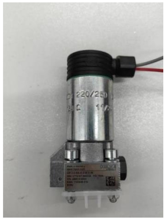
Figure 9.
Sample switching coil.
3.2. Test Content
3.2.1. Fault Settings and Simulation Methods
- (1)
- Abnormal coil circuit voltage faults
During the actual operation of GCB, a power supply voltage drop is a common fault. The abnormal voltage fault of the switching coil circuit is manifested as the abnormal value of the control circuit voltage, and when the power supply voltage drop is more serious, it will cause the moving core to move too slowly, thus leading to the failure of the switching process. The test simulates the abnormal circuit voltage fault by changing the DC voltage value in the control circuit. Respectively change the voltage of the switching coil circuit to 220 V (normal condition), 210 V, 200 V, 190 V, and 180 V, and collect the current waveforms of the coil under different voltages for the switching operation.
- (2)
- Coil circuit contact faults
In the actual operation of the GCB, the coil circuit wiring is affected by humidity, heat, and other environmental factors, which, under the action of corrosion, lead to poor contact of the switching coil circuit. The fault of poor contact of the switching coil circuit is manifested by the increase in circuit resistance. Test through the series resistance to change the resistance of the coil circuit to simulate the actual poor contact coil, respectively, in the switching coil circuit without series resistance (normal conditions), with 10 Ω, 20 Ω, 30 Ω, and 40 Ω resistance, and the collection of the coil at different voltages for the opening and closing operation of the current waveforms.
- (3)
- Coil core jamming failure
During the actual operation of GCB, the movement of the moving core is obstructed due to the aging or rusting of the core parts and eccentricity. The test simulates the core jamming fault by increasing the mass of the moving core. Increase the mass of 100 g, 300 g, and 500 g of moving core, respectively. The closing operation is carried out, and the current waveforms of the coil under different voltages for the opening and closing operations are collected.
3.2.2. Analysis of Test Results
- (1)
- Abnormal coil circuit voltage faults
The obtained results are shown in Figure 10. When the coil control voltage is reduced, the current passing through the switching coil is reduced, and the electromagnetic force on the core is reduced, leading to a reduction in the movement speed of the core and an increase in the time required for the core to reach the maximum stroke. The test results are consistent with the simulation results.
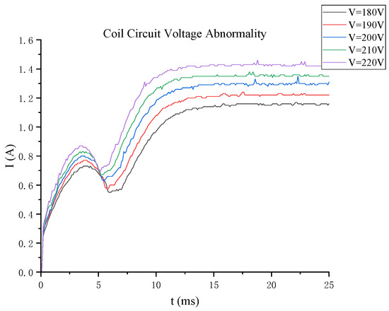
Figure 10.
Waveform of fault current of coil circuit voltage abnormality.
- (2)
- Poor contact fault of coil circuit
As shown in Figure 11, similar to the abnormal voltage fault, the increase in coil resistance will reduce the current passing through the switching coil, which in turn affects the reduction of the size of the electromagnetic force on the core, leading to a reduction in the speed of movement of the core, and ultimately leading to the core reaching the maximum movement of the stroke of the time increases and reaching the steady state when the current decreases. The test results are consistent with the simulation results.
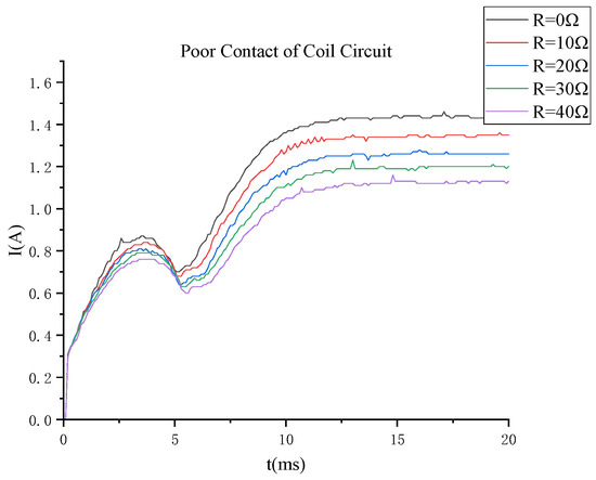
Figure 11.
Fault current waveform of poor contact of coil circuit.
- (3)
- Coil core jamming failure
As shown in Figure 12, with the increase in the mass of the moving core, the time for the first peak of the switching coil current waveforms to reach the first peak is shifted, and the time for the core to reach the maximum movement distance is also shifted. The test results are consistent with the simulation results.
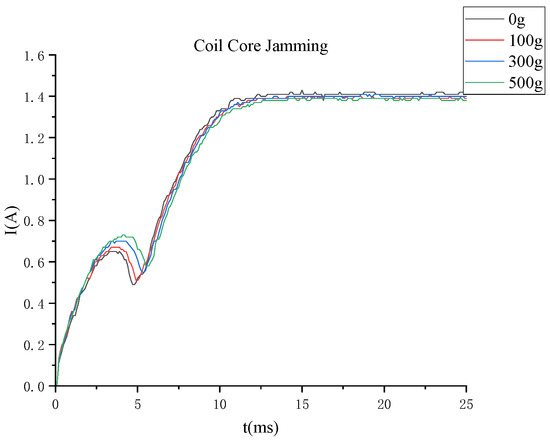
Figure 12.
Coil core jamming fault current waveforms.
4. Conclusions
In this paper, an electromagnetic field simulation model of the generator outlet circuit breaker (GCB) breaking coil has been established and validated through a fault simulation test platform. The study systematically analyzes the influence of three typical faults—abnormal circuit voltage; poor circuit contact; and core jamming—on the breaking coil’s current waveform. The high consistency between simulation and experimental results verifies the model’s accuracy and reliability.
The research provides a practical foundation for developing non-intrusive online monitoring systems for GCB switching coils. The identified characteristic current signatures can be implemented in protective relays or dedicated monitoring devices to enable early fault detection and predictive maintenance strategies, potentially reducing unplanned outages and improving power system reliability. The current study was conducted under controlled laboratory conditions using simulated faults. While the investigated faults represent the most common failure modes, real-world applications may involve more complex scenarios, including combined faults or environmental factors not considered in this study. Future work will focus on field validation and developing automated fault diagnosis algorithms based on the established current signature database.
Author Contributions
Conceptualization, Y.G.; methodology, J.W.; software, M.Y.; validation, Y.R.; formal analysis, G.X.; investigation, Y.W. (Yexing Wang); resources, Y.W. (Yu Wang); data curation, J.L.; writing—original draft preparation, J.L.; writing—review and editing, J.B.; visualization, J.B.; supervision, Y.W. (Yu Wang); project administration, Y.W. (Yu Wang); funding acquisition, Y.W. (Yu Wang). All authors have read and agreed to the published version of the manuscript.
Funding
This research was funded by China Yangtze Power Co., Ltd., grant number Z152302037.
Data Availability Statement
Data are contained within the article.
Acknowledgments
Thanks to all the authors for their support.
Conflicts of Interest
Authors Yujing Guo, Junqing Wang, Ming Yu, Yingbing Ran, Ge Xu, and Yexing Wang were employed by China Yangtze Power Co., Ltd. The remaining authors declare that the research was conducted in the absence of any commercial or financial relationships that could be construed as potential conflicts of interest. The authors declare that this study received funding from China Yangtze Power Co., Ltd. The funder was not involved in the study design, collection, analysis, interpretation of data, the writing of this article, or the decision to submit it for publication.
Abbreviations
The following abbreviations are used in this manuscript:
| GCB | Generator Circuit Breaker |
References
- Dai, Q.; Jiao, F. Research on online monitoring of high voltage circuit breaker mechanical characteristic. Power Syst. Technol. 2011, 7, 5–9. [Google Scholar]
- Liu, J.; Liu, Y.; Wang, C.; Chang, Z.; Du, C.; Jiang, C.; Yan, P.; Meng, G. Simulation of Typical Failures in High-Voltage Circuit Breaker Operating Mechanisms and Analysis of Changes in Characteristic Parameters. High-Volt. Electr. Appar. 2021, 57, 7–13. [Google Scholar]
- Wang, F. Research on Fault Diagnosis Technology for High-Voltage Circuit Breakers Based on Current in Closing and Opening Coils. Ph.D. Thesis, Hebei University of Science and Technology, Shijiazhuang, China, 2024. [Google Scholar]
- Yang, Y.; Guan, Y.; Chen, S.; Wang, J.; Zhao, K. A Method for Diagnosing Mechanical Faults in High-Voltage Circuit Breakers Based on Acoustic Signals. Trans. Chin. Soc. Electr. Eng. 2018, 38, 6730–6736. [Google Scholar]
- Sun, Y.; Zhang, W.; Zhang, Y. Research on feature value extraction and fault recognition of coil current signal in high -voltage circuit breaker. High Volt. Appar. 2015, 51, 134–139. [Google Scholar]
- Fan, X.; Tusongjiang, K.; Wang, D.; Liu, P.; Ma, X. Extraction of Current Characteristic Values for High-Voltage Circuit Breaker Closing and Opening Coils Based on VMD Modal Components. Mod. Electron. Technol. 2023, 46, 107–112. [Google Scholar]
- Qi, B.S. Research on fault diagnosis of high-voltage circuit breaker based on the improved BP neural network. In Proceedings of the 2nd International Conference on Information Science and Engineering, Hangzhou, China, 4–6 December 2010; pp. 1460–1463. [Google Scholar]
- Zhou, G. Design of a Current Detection and Fault Diagnosis System for Vacuum Circuit Breaker Closing and Opening Coils. Ph.D. Thesis, Dalian Jiaotong University, Dalian, China, 2023. [Google Scholar]
- Rudsari, F.N.; Razi-Kazemi, A.A.; Shoorehdeli, M.A. Fault analysis of high-voltage circuit breakers based on coil current and contact travel waveforms through modified SVM classifier. IEEE Trans. Power Deliv. 2019, 34, 1608–1618. [Google Scholar] [CrossRef]
- Li, T.; Pang, X.; Fan, H.; Zhen, L.; Gu, C.; Dong, C. Fault Diagnosis Method for Circuit Breaker Closing and Opening Coils Based on IEMD and GA-WNN. China Electr. Power 2022, 55, 111–121. [Google Scholar]
- Yi, Y.; Peng, Z.; Zhang, S.; Wang, S.; Liu, K.; Chen, X. Research on engineering simulation technology of high voltage circuit breaker opening and switching coils. High Volt. Electr. Appar. 2020, 56, 138–142. [Google Scholar]
- Li, D.; Xu, D.; Sun, Y. The research on fault diagnosis and test method of circuit breaker based on the coil current. High Volt. Appar. 2015, 51, 114–118. [Google Scholar]
- Li, H.; Xie, Z.; Wang, J. Fault diagnosis of the coil of high voltage circuit breaker based on K⁃S test method and SVM. Electr. Saf. 2016, 35, 53–58. [Google Scholar]
- Strachan, S.M.; McArthur, S.D.J.; Stephen, B.; McDonald, J.R.; Campbell, A. Providing decision support for the condition⁃based maintenance of circuit breakers through data mining of trip coil current signatures. IEEE Trans. Power Deliv. 2007, 22, 178–186. [Google Scholar] [CrossRef]
- Wang, Y. Exploration of circuit breaker opening and switching coil state detection and protection system. Theory Algorithm 2014, 24, 27–29. [Google Scholar]
- Li, J.; Quan, J.; Chen, J. The fault analysis on switch of a converter station based on the coil current. High Volt. Appar. 2015, 51, 141–145. [Google Scholar]
Disclaimer/Publisher’s Note: The statements, opinions and data contained in all publications are solely those of the individual author(s) and contributor(s) and not of MDPI and/or the editor(s). MDPI and/or the editor(s) disclaim responsibility for any injury to people or property resulting from any ideas, methods, instructions or products referred to in the content. |
© 2025 by the authors. Licensee MDPI, Basel, Switzerland. This article is an open access article distributed under the terms and conditions of the Creative Commons Attribution (CC BY) license (https://creativecommons.org/licenses/by/4.0/).