Article

Robust UAV Path Planning Using RSS in GPS-Denied and Dense Environments Based on Deep Reinforcement Learning

Department of Electronic Convergence Engineering, Kwangwoon University, Seoul 01897, Republic of Korea
*
Author to whom correspondence should be addressed.
Electronics 2025, 14(19), 3844; https://doi.org/10.3390/electronics14193844
Submission received: 31 July 2025 / Revised: 26 September 2025 / Accepted: 26 September 2025 / Published: 28 September 2025

Abstract

A wide range of research has been conducted on path planning and collision avoidance to enhance the operational efficiency of unmanned aerial vehicles (UAVs). The existing works have mainly assumed an environment with static obstacles and global positioning system (GPS) signals. However, practical environments have often been involved with dynamic obstacles, dense areas with numerous obstacles in confined spaces, and blocked GPS signals. In order to consider these issues for practical implementation, a deep reinforcement learning (DRL)-based method is proposed for path planning and collision avoidance in GPS-denied and dense environments. In the proposed method, robust path planning and collision avoidance can be conducted by using the received signal strength (RSS) value with the extended Kalman filter (EKF). Additionally, the attitude of the UAV is adopted as part of the action space to enable the generation of smooth trajectories. Performance was evaluated under single- and multi-target scenarios with numerous dynamic obstacles. Simulation results demonstrated that the proposed method can generate smoother trajectories and shorter path lengths while consistently maintaining a lower collision rate compared to conventional methods.

1. Introduction

In recent decades, unmanned aerial vehicles (UAVs) have been employed in various fields of disaster management, such as search-and-rescue and data collection, due to their high mobility and sensor scalability [1]. Applications of UAVs are expanding to complex tasks in environments with dynamic obstacles [2]. In such complex environments, path planning and collision avoidance are essential for reliable and efficient flight, as suboptimal path design can lead not only to diminished efficiency but also to a high risk of collisions. Therefore, path planning and collision avoidance have received significant attention, specifically in environments with multiple unknown UAVs [3].
To ensure safe and efficient UAV flights, numerous path planning studies have been conducted [1]. As representative node-based path planning algorithms, Dijkstra [4] and A* [5], which are well-known for finding optimal paths in static and discrete environments, have been developed. However, the computational complexity increases significantly in large-scale or continuous spaces, leading to reduced efficiency. As a way to handle high-dimensional spaces, sampling-based path planning algorithms, a rapidly-exploring random tree (RRT) [6,7] and RRT* [8], have been proposed. The RRT algorithm has been widely used in UAV path planning because fast and efficient search is enabled, and prior modeling of the environment is not required. However, in the RRT algorithm, new nodes are connected to the nearest node, which reduces the likelihood of obtaining the shortest route and limits adaptability to dynamic obstacles. To overcome the limitations of RRT, RRT* explores all neighboring nodes around a new node and finds the optimal path by rewiring the route. While RRT* can remain effective even when obstacles move slowly, its application to UAVs in dynamic environments may be constrained, as it performs repeated calculations to avoid collisions with obstacles. Distinct from the node-based search methods, the artificial potential field (APF) method guides the UAV using attractive and repulsive forces [9,10]. APF generates an attractive force at the destination point and a repulsive force at obstacles, guiding the UAV towards the destination while avoiding potential collisions. The APF method may be characterized by computational efficiency but be vulnerable to local minima, where the UAV may not reach the destination due to the repulsion of obstacles [11,12]. Moreover, swarm intelligence algorithms, including ant colony optimization [13], differential evolution [14], and particle swarm optimization [15], have been increasingly applied to UAV path planning due to their robustness in global search and iterative optimization. However, in high-dimensional search spaces, these algorithms may exhibit slow convergence and path deviations, which can cause entrapment in local minima [16].
To address the limitations of these conventional algorithms, deep reinforcement learning (DRL)-based approaches have increased accessibility by presenting a new paradigm that learns an optimal policy through interaction with the environment [17]. A DRL agent can learn an optimal policy for simultaneous path planning and collision avoidance through direct interaction with the environment, demonstrating superior performance over conventional methods, particularly in dynamic settings [18,19,20]. However, DRL-based dynamic obstacle avoidance research typically assumes an ideal environment where obstacle positions are either pre-known or can be acquired through camera and LiDAR sensor data [21]. In addition, existing DRL-based methods have primarily focused on avoiding static obstacles in wide-area environments where the global positioning system (GPS) is available [22]. The assumption of GPS availability breaks down in many real-world mission areas, such as indoors, urban canyons, and sites with signal interference, known as GPS-denied environments [23]. A policy learned with GPS information is often unreliable in the GPS-denied environments [24]. Therefore, robust and reliable path planning and collision avoidance methods are required to ensure stable UAV mission execution in complex environments where obstacles are dense and dynamic, and GPS-denied.
To enable GPS-denied path planning, alternative methods for environmental perception are required. Received signal strength (RSS) has been considered as a promising solution for enabling DRL agents to perceive the GPS-denied environment [25]. RSS can offer a solution due to its low cost and ease of implementation, requiring minimal hardware [23]. The fundamental principle is that RSS values from a transmitting object decay with distance according to a path loss model [26]. By measuring the signal strength, an agent can therefore estimate its proximity to obstacles, a concept that has been used for indoor localization, environmental mapping, and object tracking [27]. However, existing applications of RSS are often insufficient for the unique challenges of autonomous UAV flight in complex operational zones. Numerous scenarios are simultaneously GPS-denied and are involved in multiple unknown, dynamic UAVs [24]. Examples include search-and-rescue operations in collapsed buildings, infrastructure inspection within dense urban canyons or beneath large bridges, and automated logistics in large indoor warehouses [28]. In these environments, pre-existing maps are often unavailable, and the primary threat comes from other mobile agents.
To utilize RSS for the path planning and collision avoidance training of a DRL agent, it is essential to mitigate the instability caused by signal noise and interference [26]. Given the inherent nonlinear relationship between RSS and distance, a filter that can handle the nonlinearity and dynamics is required. The extended Kalman filter (EKF) can be an effective method for filtering such noise from nonlinear sensor data [29]. The EKF can offer a balance between performance and computational complexity, making it an effective choice for real-time UAV navigation [30]. By integrating the EKF, a more reliable state information stream can be provided to the DRL agent, which is essential for learning robust collision avoidance policies.
In this paper, a novel method is proposed to address the path planning and collision avoidance problem in GPS-denied and dense environments with dynamic unknown UAVs. While RSS has been used for positioning [25], research on directly applying RSS to real-time collision avoidance in GPS-denied environments with multiple unknown UAVs remains limited. In the proposed framework, state input to the DRL agent is provided by estimates derived from the strongest RSS signals received from surrounding UAVs. The DRL agents learn to interpret complex patterns of uncertain distance estimates using RSS, thereby determining the optimal action to avoid collisions. As a result, the learned policy enables robust path planning with minimal sensor data, eliminating the need for GPS. Furthermore, in contrast to the grid-based action spaces adopted in prior studies, the proposed method directly outputs control commands that adjust the UAV’s attitude. This is achieved through attitude control, smooth collision avoidance, and the efficient trajectory generation that reflects the true kinematic characteristics of real UAVs. The main contributions of this paper are as follows:
  • A novel collision avoidance method is proposed under the GPS-denied condition. Unlike existing works that require GPS signals, the proposed method is developed to avoid collision using the strongest RSS measured from surrounding UAVs. In the proposed framework, an EKF is applied to mitigate noise and interference, which are related to RSS fluctuations. By filtering out the fluctuations in RSS, the accuracy of distance estimation and the reliability of collision avoidance can be enhanced.
  • To simultaneously achieve a smooth and efficient trajectory by considering the dynamic multiple unknown UAVs, a novel strategy is proposed that utilizes the DRL method. Instead of the grid-based action, the proposed method enables relatively smooth path planning and collision avoidance by applying the UAV’s attitude.
  • Unlike previous methods that assume a no-fly zone, the simulation is performed considering a 3D dense environment where numerous unknown UAVs exist in the environment. Specifically, two scenarios are considered for comprehensive performance evaluation: single- and multi-target scenarios. The simulation results demonstrate that the proposed method is practically applicable even in challenging environments.
The remainder of this paper is organized as follows. Section 2 describes the system model, including the RSS-based distance estimation by the EKF. Section 3 describes the UAV kinematic and position model. Section 4 describes the DRL-based system for path planning and collision avoidance. Section 5 presents the simulation results, demonstrating the effectiveness of the proposed method in various scenarios. Finally, Section 6 concludes the paper and discusses future research directions.

2. System Model

The proposed system model for collision avoidance in GPS-denied environments is depicted in Figure 1. In the proposed system model, two situations are assumed. One situation is pertinent to the case of a user UAV passing through an environment where an unknown UAV, whose exact position is unknown, broadcasts standardized basic identification signals. The other is the case where the user UAV can measure the RSS of surrounding UAVs based on sensors mounted on the aircraft. It also assumes that the GPS signals representing the position of other UAVs cannot be measured. In wireless communication environments, the log-distance path loss model is formulated, assuming an unobstructed airspace. In addition, no packet errors or information omissions are assumed.
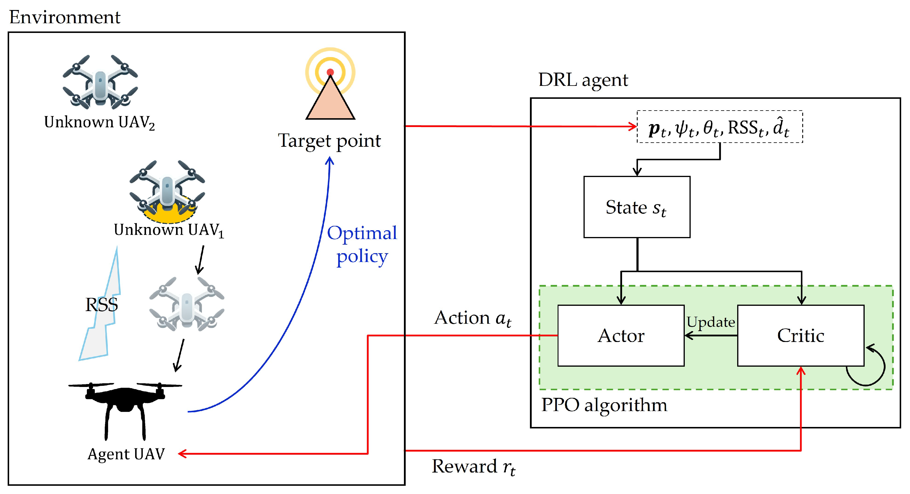
In the proposed system model, the user UAV performs path planning and collision avoidance by measuring the RSS of surrounding UAVs using its mounted sensors. The higher the number of antennas mounted on the UAV, the more angular information can be calculated from the RSS. However, in this paper, one antenna is assumed to be used, and the user UAV focuses on the strongest signal, which represents the closest unknown UAV. As raw RSS values exhibit significant fluctuations and are difficult to utilize directly, the EKF is applied to mitigate signal noise. Based on the filtered RSS, a more accurate estimate of the distance to the unknown UAV is obtained. The estimated distance refined through EKF is input as state information for the DRL agent. The DRL agent learns an optimal policy for path planning and collision avoidance based on estimated distance and other state information. To ensure physically feasible and smooth trajectories, kinematic and positioning models are incorporated, reflecting the real-world dynamics of the UAV. A detailed description of the kinematic and positioning model is provided in Section 3.

2.1. Path Loss Model

In the proposed system model, the RSS is obtained using the log-distance path loss model [25,31], which is a widely used wireless channel model. The received power from the transmitter is given by
P rx = P tx + 10 log 10 C 10 η log 10 d t d 0 + X σ ,
where P tx is the transmitted power, C is a constant determined by the antenna gain and system parameters, η is the path loss exponent, d 0 is the reference distance, and X σ is a Gaussian random variable representing shadow effects. d t is the distance from the transmitter to the receiver at time t, representing the distance between the user UAV and the unknown UAV. Equation (1) can be expressed in terms of the RSS as follows:
RSS t = P rx P tx 10 log 10 C = 10 η log 10 d t d 0 + X σ ,
Under the assumption that d 0 is one, the distance between the user UAV and the unknown UAV at time t can be derived as follows:
d t = 10 RSS t X σ 10 η .

2.2. RSS-Based Distance Estimation Algorithm

Distance estimation using RSS can lead to significant errors because the RSS can vary greatly from the predicted value due to environmental factors such as multipath fading, noise, and shadowing [26]. In particular, the logarithmic nature of the path loss model tends to amplify these small changes in signal strength into large distance errors. The relationship between RSS and distance, as defined in Equation (3), is inherently nonlinear due to its logarithmic nature. This nonlinearity renders the standard KF, which is optimal only for linear systems, unsuitable for this task as it would introduce significant estimation errors [29,30]. The EKF enables recursive state estimation by incorporating both the system dynamics and the nonlinear measurement model [29]. The EKF provides a balance between performance and computational complexity, making it a practical and effective choice for real-time applications [32].
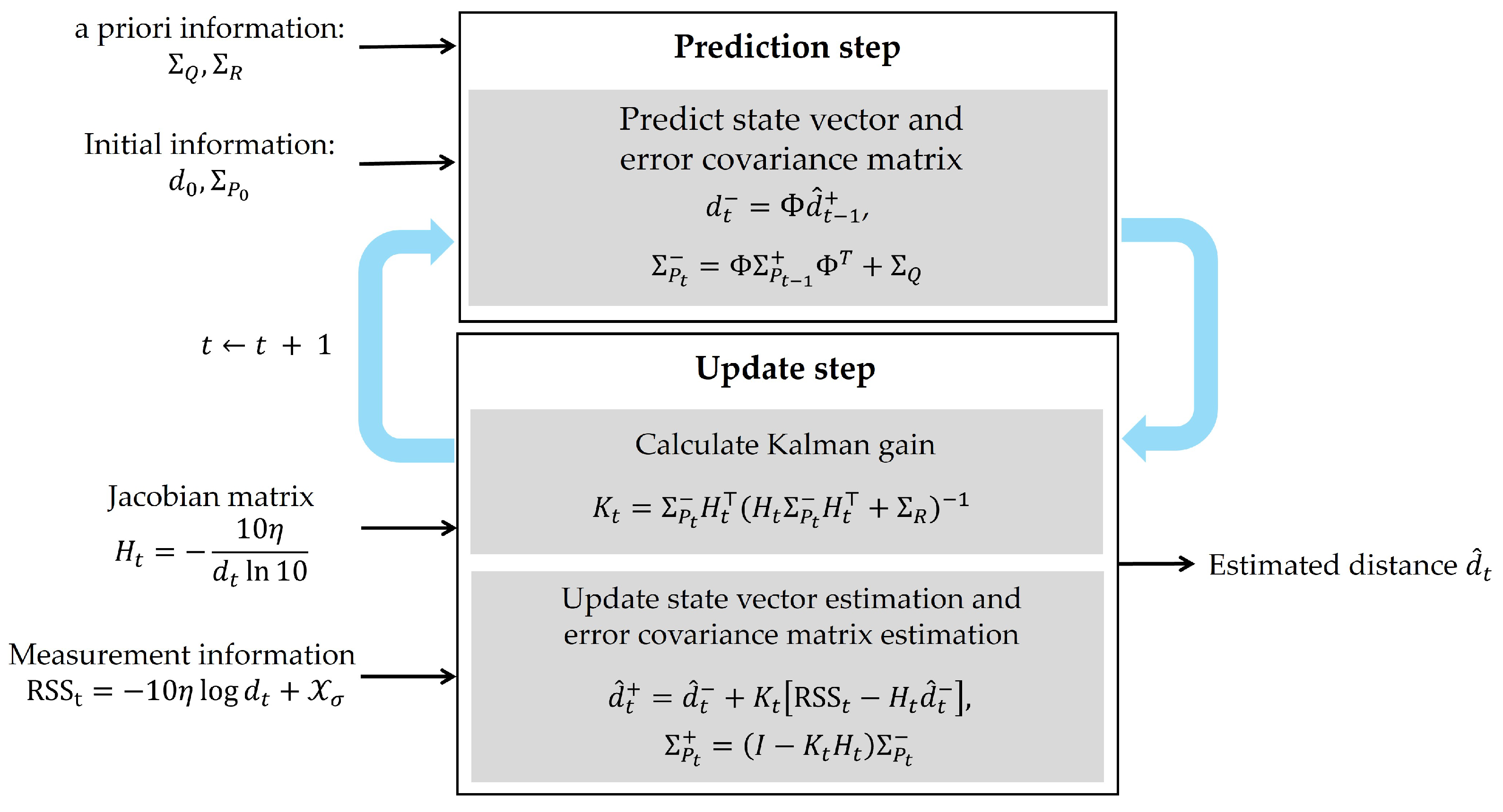
The EKF consists of a prediction step and an update step. In the prediction step, it is assumed that the distance increment by the UAV over a certain period is negligible, so the distance value of the previous step is simply maintained. The predicted distance at time t can be described as follows:
d ^ t = Φ d ^ t 1 + ,
Σ P t = Φ Σ P t 1 + Φ + Σ Q .
where d ^ t is the predicted state variable, Σ P t is the predicted covariance matrix, Φ is the state transition matrix, and Σ Q is the process noise covariance matrix. The state variable d t is a one-dimensional variable representing the distance between the user UAV and the unknown UAV. For this case, the transition matrix Φ can be simplified to an identity matrix. The process noise covariance matrix Σ Q is set to a small value to reflect the assumption that the distance increment is negligible. The superscript “−” indicates the predicted value of the prediction step, while the superscript “+” indicates the updated value of the update step.
In the update step, the RSS measurement is used to update the state variable and covariance matrix as described in Equation (2). The measurement noise is assumed to be Gaussian with zero mean and covariance matrix Σ R as X σ N ( 0 , Σ R ) . The Jacobian matrix is defined as follows:
H t = RSS t d t = 10 η d t ln ( 10 ) .
The EKF computes the Kalman gain through H t . The Kalman gain is derived as follows:
K t = Σ P t H t H t Σ P t H t + Σ R .
The updated state variable and covariance matrix are calculated as follows:
d ^ t + = d ^ t + K t [ RSS t H t d ^ t ] ,
Σ P t + = ( I K t H t ) Σ P t .
where d ^ t + is the updated state variable, representing the estimated distance between the user UAV and the unknown UAV at t, Σ P t + is the updated covariance matrix, and I is the identity matrix. The EKF algorithm for distance estimation is summarized in Figure 2.

3. UAV Kinematic and Positioning Model

In this section, the fundamental kinematic and positioning models are established to enable the DRL agent to operate effectively in the GPS-denied environment. The kinematic model describes how the linear and angular velocities of the UAV are geometrically mapped to the rate of change of attitude variables. Here, the kinematic model is defined based on the rotary-wing UAV. The positioning model is used to track the position and orientation of the UAV relative to the target within a locally defined reference frame using the time derivatives of the attitude and position states derived from the kinematic model. The motivation of defining both the kinematic and positioning models is two-fold. First, the kinematic model can provide a realistic representation of the UAV’s motion dynamics, which is crucial for safely navigating dense environments and ensuring the agent’s learned policy generates physically feasible and smooth trajectories [33]. Second, the positioning model can introduce a relative body-fixed coordinate system, enabling the tracking of the UAV’s position and orientation relative to the target at each time interval [34]. Aerial navigation relies on an absolute coordinate system, which requires continuous access to GPS. However, the dependency on GPS can pose a significant challenge in GPS-denied environments. To address this challenge, a relative body-fixed coordinate system [34], which reframes the navigation problem from an absolute to a relative perspective, is proposed. Here, prior knowledge of the start and target positions is assumed by the DRL agent for successful missions. The use of relative body-fixed transformation offers a significant advantage by simplifying the learning problem for a DRL agent. Consequently, UAV kinematic and positioning models can provide precise and reliable state information that is a prerequisite for the successful learning and operation of the DRL agent presented in Section 4.
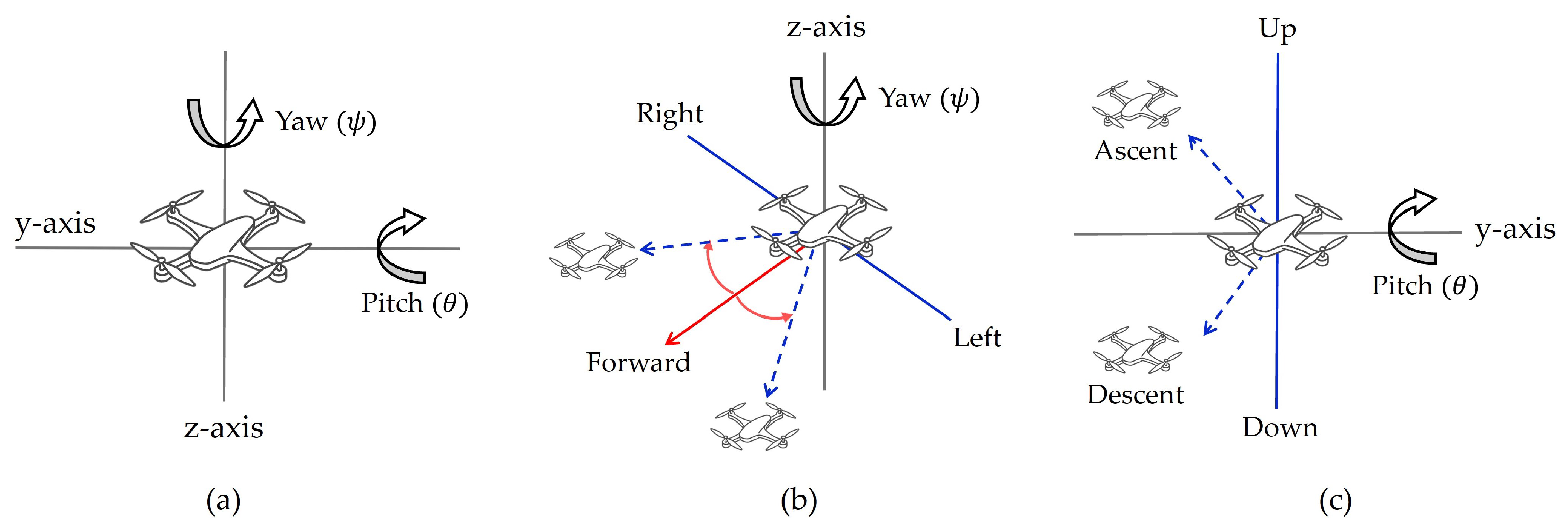
The UAV’s attitude defines the coordinate translation relationship from the global coordinate system to the body-fixed coordinate system [34]. In Figure 3, the main rotational motions used to represent the attitude of the UAV are described. The orientation of a UAV in 3D space is generally defined by three Euler angles [33]. The yaw angle ( ψ ) represents rotation around the z-axis, which controls the left and right turning motion of the UAV’s nose. The pitch angle ( θ ) represents rotation around the y-axis, which controls the movement of ascent and descent. The roll angle represents rotation around the x-axis, which controls the tilt of the UAV’s wings. In this paper, only ψ and θ angles are considered as they are directly related to path planning and collision avoidance. The roll angle is set to zero under the assumption that the UAV maintains a horizontal attitude.
The simplification of setting the roll angle to zero was made to focus on the essential aspects of path planning and collision avoidance while avoiding complexity. In the proposed method, the initial position of the UAV is assumed to be p 0 = ( x 0 , y 0 , z 0 ) and the target position is p G = ( x G , y G , z G ) . Defining the target point as the relative origin, the shifted initial position of the UAV p 0 is expressed as follows:
p 0 = p 0 p G = ( x 0 x G , y 0 y G , z 0 z G ) .
To represent the UAV’s position in the body-fixed coordinate frame, a transformation from the global coordinate system is performed using the ψ and θ , as follows:
p = R ( θ , ψ ) p 0 ,
where p denotes the UAV’s position vector in the body-fixed frame and R ( θ , ψ ) is the Z-Y Euler rotation matrix defined as the combination of ψ rotation R z ( ψ ) about the z-axis and θ rotation R y ( θ ) about the y-axis. The combined rotation matrix is defined as follows [33,35,36,37]:
R ( θ , ψ ) = R z ( ψ ) R y ( θ ) = cos ( ψ ) sin ( ψ ) 0 sin ( ψ ) cos ( ψ ) 0 0 0 1 cos ( θ ) 0 sin ( θ ) 0 1 0 sin ( θ ) 0 cos ( θ ) = cos ( ψ ) cos ( θ ) sin ( ψ ) cos ( ψ ) sin ( θ ) sin ( ψ ) cos ( θ ) cos ( ψ ) sin ( ψ ) sin ( θ ) sin ( θ ) 0 cos ( θ )

4. DRL-Based Path Planning and Collision Avoidance

The proposed DRL-based framework is shown in Figure 4. Within the proposed framework, the DRL agent interacts with the environment by selecting actions a t . The state s t of the environment is defined by fundamental information, which includes the RSS measurement and estimated distances described in Section 2.2. The agent receives a reward r t based on the actions taken and the resulting state of the environment. In this paper, the proximal policy optimization (PPO) algorithm [38], which utilizes an actor–critic architecture, is applied to train the DRL agent. Through interactions with the environment, the agent learns an optimized policy that enhances path planning and collision avoidance.

4.1. State and Action Spaces

The state space contains relevant information necessary for the UAV to make decisions and reflects dynamic changes in the environment. s t is defined as follows:
s t = { p t , ψ t , θ t , RSS t , d ^ t } ,
where p t denotes the UAV’s body-fixed position coordinates at each time step t as described in Section 3, ψ t and θ t represent the UAV’s yaw and pitch angles, RSS t is the measured RSS at each time step t, and d ^ t denotes the estimated distance to the unknown UAV obtained from the EKF. The s t is updated at each time step t and designed to provide a representation of the UAV’s current state. The state with estimated distance information is essential for the DRL agent to make decisions about its actions in the environment.
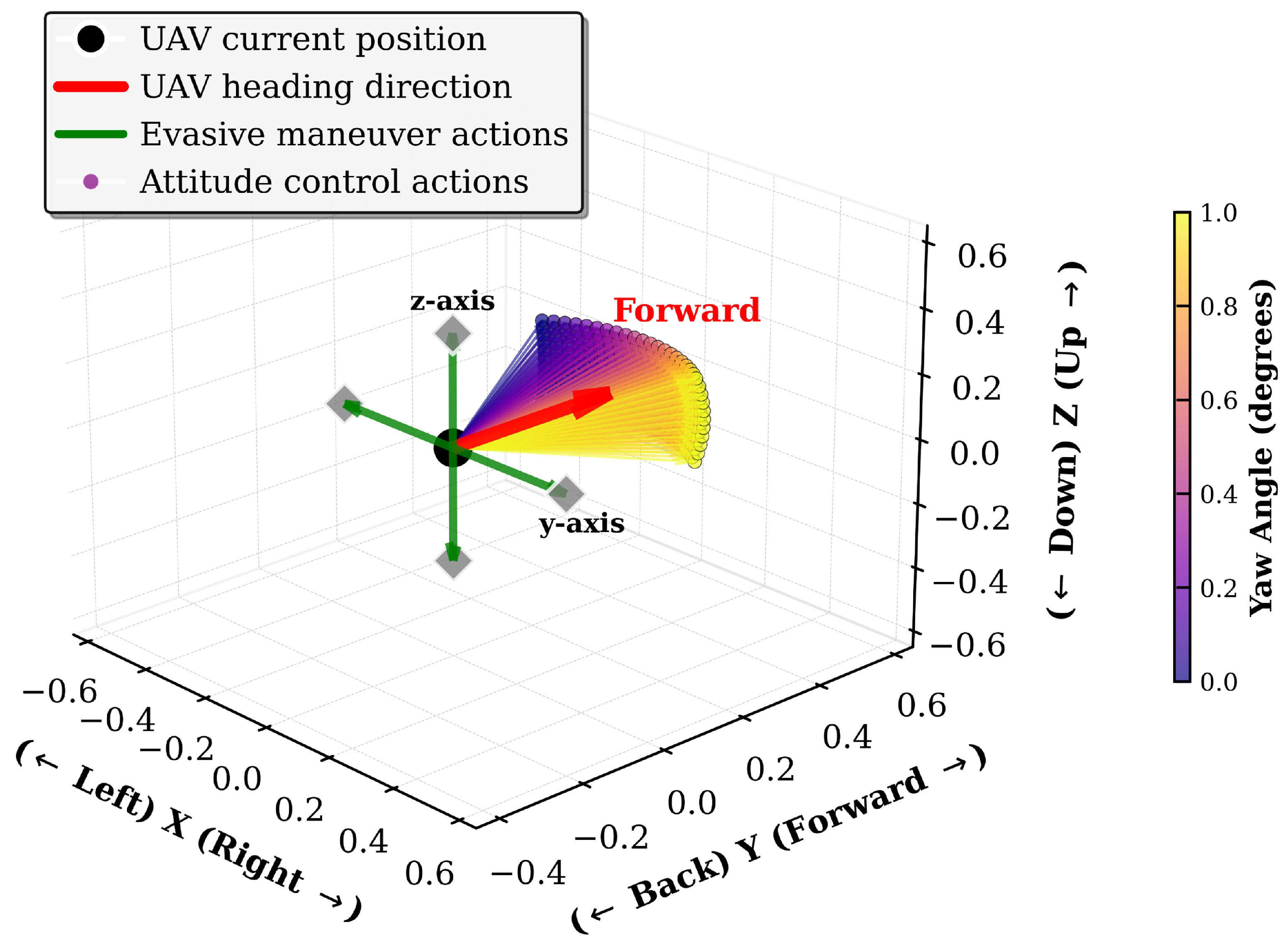
The a t is composed of two distinct subsets designed for different purposes: a set of evasive maneuvers for rapid collision avoidance and a set of attitude control actions for smooth and efficient path planning. At each time step, the agent selects one action from the defined a t to navigate towards the target point while avoiding potential collisions with unknown UAVs. The evasive maneuver actions consist of six discrete movements: stop, forward, yaw right, yaw left, pitch up, and pitch down. These actions are designed to produce immediate changes in the UAV’s state to avoid imminent threats. The stop action serves as an emergency braking by setting ψ t , θ t , and the UAV’s velocity to zero. The forward action maintains the previous attitude and continues along with the current trajectory. The yaw right and yaw left actions command large rotational changes in the ψ t angle for rapid horizontal evasion. The pitch up and pitch down actions set the θ t angle to zero for vertical avoidance. The attitude control actions are used for precise control of the UAV’s movement by adding a small increment. For these actions, the change in the yaw angle ψ t is set from −30 to 30 degrees in 3-degree steps, and the change in the pitch angle θ t is set from −15 to 15 degrees in 3-degree steps. Once an action is selected and applied, the direction vector u t for the UAV is calculated as follows [33]:
u t = v cos ( ψ t ) cos ( θ t ) v sin ( ψ t ) cos ( θ t ) v sin ( θ t ) ,
where v is the speed of the UAV. The total number of actions is 236, which is the sum of 6 evasive maneuver actions and 230 attitude control actions. The a t variables and ranges are summarized in Table 1, and the actionable region for UAV is shown in Figure 5.

4.2. Reward Function

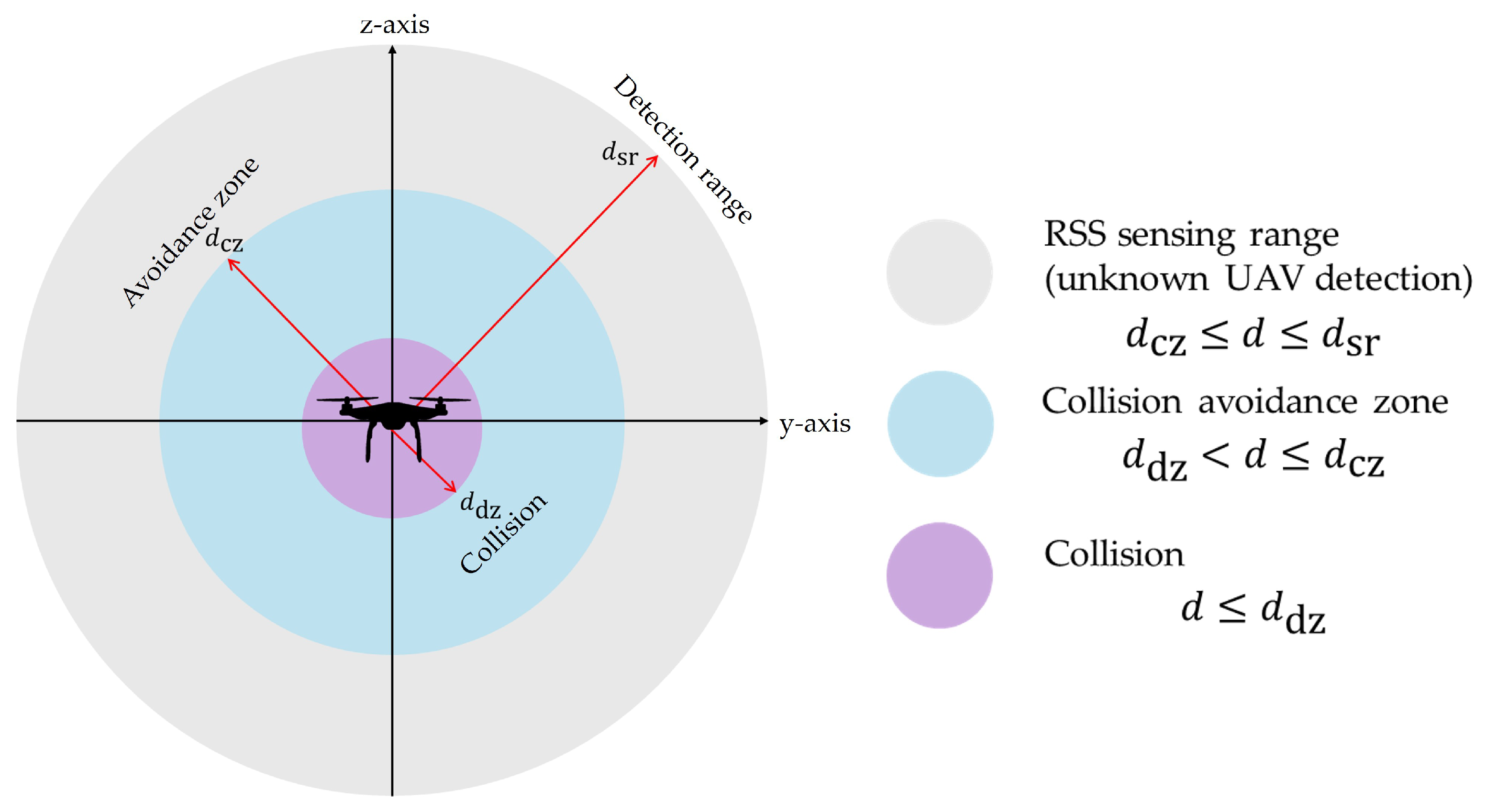
The UAV cannot obtain complete information about the environment during flight and can only obtain information within a certain range centered on itself through RSS measurement values. The maximum RSS sensing range of the UAV agent is denoted as d sr . Several safety zones are established to ensure collision avoidance of the UAV. A collision avoidance zone is set as d cz and is used to calculate a behavioral reward for the DRL agent. The configuration serves as a trigger mechanism for the UAV’s collision avoidance and safety maintenance strategies. A collision is defined as an event where the distance to an unknown UAV becomes less than the collision distance, denoted as d dz . The collision event is treated as a termination condition for the DRL agent. These safety zones are shown in Figure 6.
The policy of the DRL agent is updated based on the reward signal received from the environment. Two main reward functions are utilized for UAV path planning and collision avoidance: direction reward and safe radius reward. These reward functions are designed with penalties whose value is negative to achieve the minimum action. The direction reward, denoted as r direction , is designed to evaluate the alignment between the agent’s current heading and the direction vector toward the target. The r direction is defined as follows:
r direction = u t · u g u t · u g ,
where u t is the current direction vector of the agent, and u g is the direction vector towards the goal point. The safe radius reward, denoted as r safe , is designed to guide the agent to maintain a safe distance from the unknown UAVs. The r safe is defined as follows:
r safe = d cz d ^ t d cz
where d cz is the collision avoidance distance, and d ^ t is the estimated distance to the unknown UAVs. The reward r t is calculated as the sum of the direction reward and safe radius reward, as follows:
r t = 10.0 if   reached   target   point 10.0 if   d ^ t d dz     ( Collision ) c 1 · r direction + c 2 · r safe if   d dz < d ^ t d cz c 1 · r direction if   d ^ t > d cz ,
where c 1 and c 2 are the weights for the direction reward and safe radius reward, respectively. The weights can be adjusted to balance the importance of each reward function.

4.3. Proximal Policy Optimization (PPO) Algorithm

The DRL framework based on the deep Q-network (DQN) [21,39] has been recognized for its sample efficiency in discrete action spaces. However, its stability may be compromised in high-dimensional spaces due to the memory burden. In contrast, the policy gradient method can handle complex state and action spaces due to its ability to learn stochastic policies [40]. As an advancement of policy gradient methodologies, the PPO [38] algorithm has been recognized for dynamic environments, as it can be effectively applied to UAV path planning and collision avoidance.
PPO achieves this stability through a clipped surrogate objective function, which ensures that policy updates remain within a reasonable range of values. The surrogate objective function L ( ω ) is defined as follows:
L ( ω ) = E min π ω ( a | s ) π ω o l d ( a | s ) A ( s , a ) , clip π ω ( a | s ) π ω o l d ( a | s ) , 1 ϵ , 1 + ϵ A ( s , a ) ,
where π ω ( a | s ) is the probability of taking action a in state s under the current policy parameterized by ω and π ω o l d ( a | s ) is the probability of taking action a in state s under the old policy. The ratio π ω ( a | s ) π ω o l d ( a | s ) is known as the importance sampling ratio, which measures the extent to which the new policy differs from the old policy. The hyperparameter ϵ is used to restrict the probability ratio to the range [ 1 ϵ , 1 + ϵ ], thereby ensuring learning stability. The term A ( s , a ) is the advantage function, which estimates how much better an action a is compared to the average action in state s. A ( s , a ) is computed as follows:
A ( s , a ) = Q ( s , a ) V ( s ) ,
where Q ( s , a ) is the action-value function that represents the expected cumulative reward for taking action a in state s, and V ( s ) is the state-value function that estimates the expected cumulative reward for being in state s. Using this objective function, the policy parameters ω are updated by maximizing L ( ω ) using stochastic gradient ascent with a learning rate α as follows:
ω ω + α ω L ( ω ) ,
where ω L ( ω ) is the gradient of the surrogate objective function with respect to the policy parameters ω .
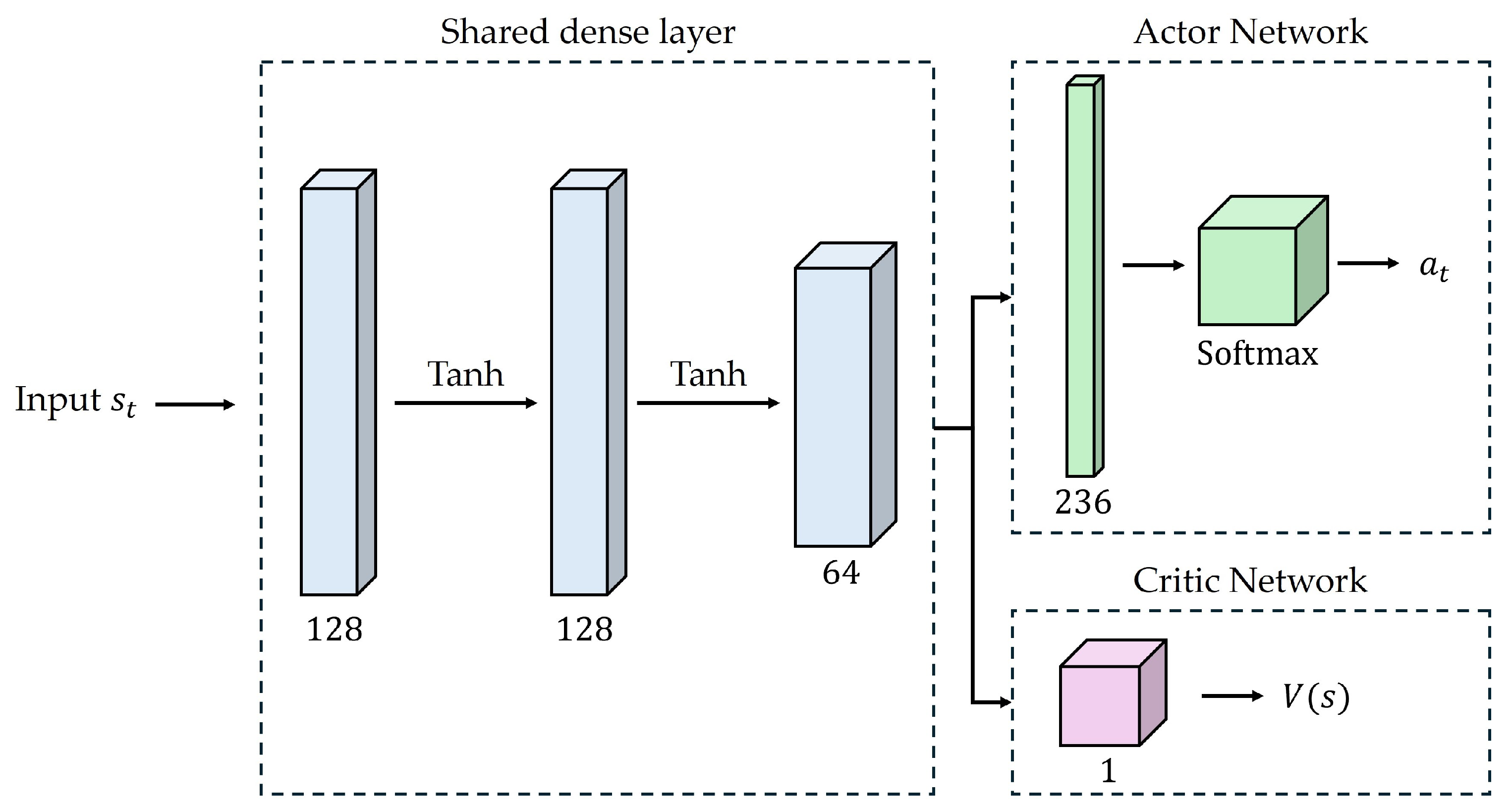
The architecture of the DRL network, implemented for the PPO algorithm, is described in Figure 7. The DRL network architecture employs shared hidden layers to enhance computational and sample efficiency. Through this design, policy and value functions are trained on a consistent representation of the state, thereby facilitating stable learning in complex environments [41]. The network receives a s t as input, which is processed through three fully connected (FC) hidden layers. The first layer maps the input to 128 neurons, while the second layer, also consisting of 128 neurons, extracts higher-level features. The third FC layer reduces the dimensionality to 64 neurons. A Tanh activation function is applied after each layer to introduce nonlinearity. The probability distribution over the action space is produced by Softmax after the 64-dimensional feature vector is expanded to 236 dimensions, which corresponds to the action space. The value function V ( s ) is obtained by mapping the 64-dimensional feature vector to a single scalar output.

5. Simulation Results

5.1. Simulation Setup

The conventional methods [6,9] for path planning often assume an environment in which UAVs operate at low altitudes. In addition, static obstacles of buildings, no-fly zones, and single-target scenarios have been mainly considered in large areas rather than multiple-target scenarios. However, UAVs can be implemented in narrow spaces, such as urban and industrial areas [3]; therefore, operation in densely built environments must be considered. To reflect the practical environmental settings, the proposed simulations consider environments where multiple unknown UAVs coexist in narrow spaces. As depicted in Figure 8, single-target and multi-target scenarios are considered. In both the single-target and multi-target scenarios, a user UAV, denoted by a gray circle, is assigned a target to navigate from a starting point to a designated target point. The single-target scenarios have a single target point, similar to previous works [21,40]. However, in multi-target scenarios, the task is to pass through two checkpoints before reaching the final target point.
The existing literature does not specify the exact range for collecting the RSS [26,28]. However, according to [42], the RSS sensing range is typically between 50 and 150 m; therefore, in the simulation, the UAV agent d sr is set to 100.0 m. The safety radius d cz is set to 50.0 m [21]. The collision threshold d dz is set to 5.0 m by assuming the UAV’s radius of 2.0 m. The speed of the UAV agent is set to 1.0 m/s. The dynamic conditions for the unknown UAVs are configured to reflect real-world situations in both scenarios. The unknown UAVs have a random speed selected from a range of 2.0 to 10.0 m/s in each simulation episode and are randomly generated at least d sr from the UAV agent. Moreover, the unknown UAVs go back and forth between the start and target points. The unknown UAVs include directions that could lead to a head-on collision with the UAV agent, directions that pass through the UAV agent’s current position, and directions that are perpendicular to the UAV agent’s trajectory. The path loss exponent η was set within a range of 2.2 to 4.0 to reflect ideal communication environments, as well as communication environments in urban and indoor settings [25]. In addition, η is randomly selected to simulate diverse communication environments. The simulation parameters are summarized in Table 2. All simulations are conducted on a system equipped with an Intel 13th Gen i7-13700F CPU, 64 GB DDR5 RAM, and an NVIDIA RTX 4070 GPU.

5.2. Simulation Results

5.2.1. Analysis of Reward Function Component

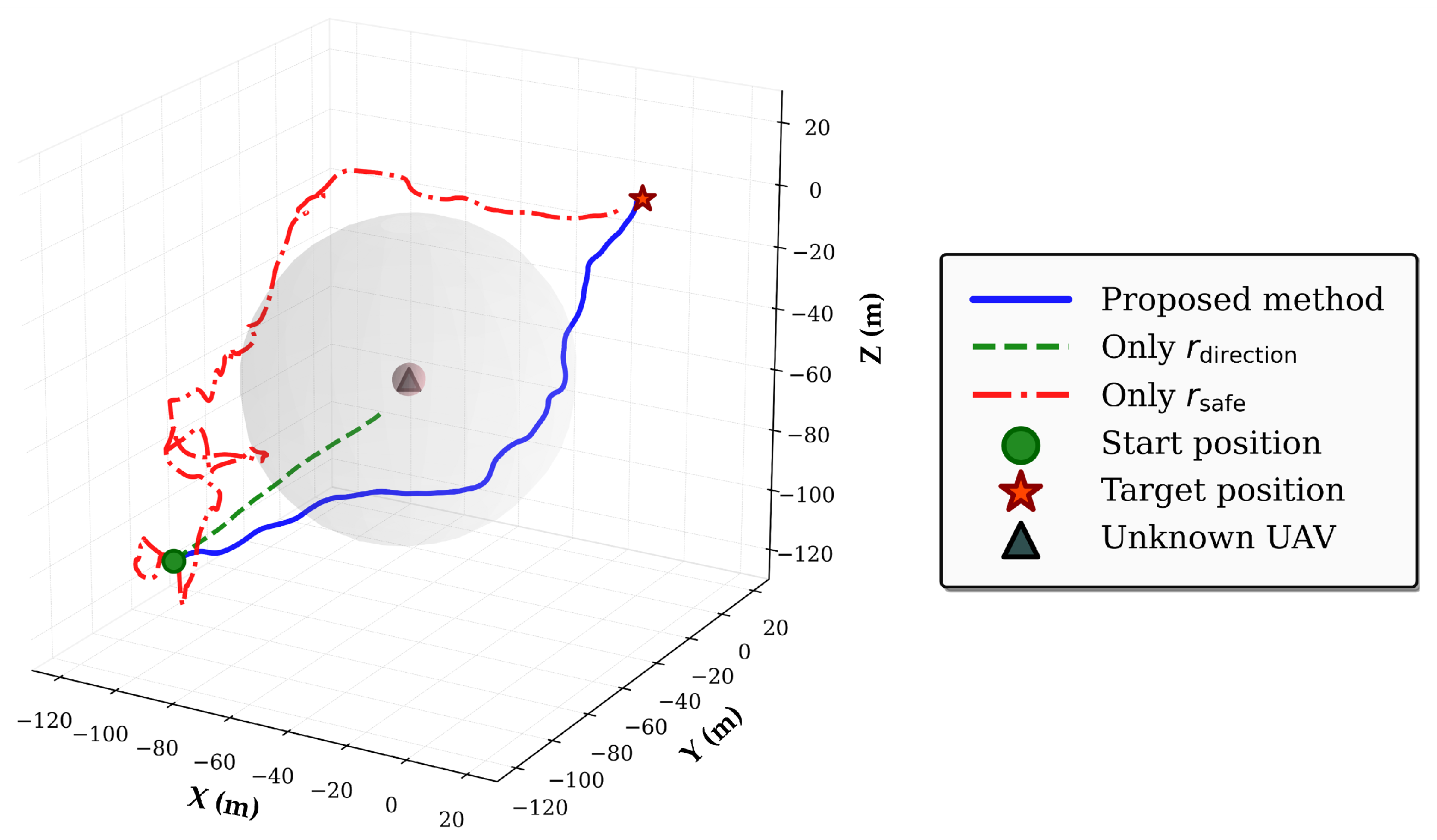
To clarify the specific impact of each individual component within the proposed reward function, an ablation study was conducted. The contribution of each component was systematically evaluated by individually removing it and observing the resulting effect on the agent’s performance. The reward function weights, c 1 and c 2 , determine the relative importance of target-oriented and collision avoidance actions, respectively. Therefore, by adjusting these values, the agent’s behavioral policy can be fine-tuned to meet specific environmental requirements. In Figure 9, typical 3D trajectories generated by the DRL agent are depicted for each ablation case. In the case where only the direction reward r direction was used, the agent learned to reach the target point without considering obstacles. Applying only the safe radius reward r safe led the agent to avoid obstacles, but the generated trajectory was inefficient compared to that generated by the proposed method. In contrast, the agent based on the proposed reward function successfully reaches the target point while maintaining a safe distance from the obstacles. Therefore, the results of the ablation study confirm that the proposed reward function can lead the agent to learn an optimal path while avoiding obstacles.

5.2.2. Collision Avoidance Performance

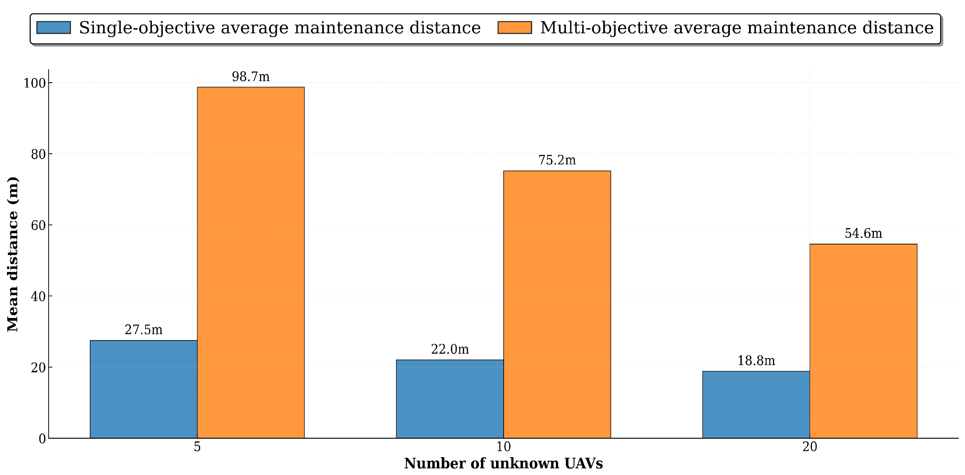
To evaluate the collision avoidance performance of the proposed method, a dedicated simulation was designed to enable quantitative analysis. The primary target was to assess how effectively the agent maintains a safe distance from dynamic threats. To ensure statistical significance, a total of 500 episodes were executed. Figure 10 shows the distribution of the distances maintained by the agent from unknown UAVs. Here, the distance to unknown UAVs was recorded for environments with 5, 10, and 20 unknown UAVs. The average distances maintained from surrounding UAVs were about 27.5 m, 22.0 m, and 18.8 m for each respective scenario. The average distances were about 98.7 m, 75.2 m, and 54.6 m. In comparison between the single-target and multi-target scenarios, lower collision rates and longer average safe distances are observed in the multi-target scenario. The multi-target scenario requires the agent to continuously adjust the path direction and plan the next checkpoint, in contrast to the single-target scenario. In this context, the agent tends to have a policy of taking a safe path in exchange for a penalty in some reward. Therefore, the proposed DRL method can be considered a robust method to avoid collisions while maintaining the efficiency of path planning even in dense environments.

5.2.3. Performance Evaluation and Discussions

To evaluate the performance of the proposed method, a comparative analysis was conducted using adaptive-APF [43], HPO-RRT* [8], and RRT [6], which are categorized as local path planning algorithms. Adaptive-APF incorporates collision risk prediction and fuzzy logic to enhance dynamic obstacle avoidance and local minimum escape performance. HPO-RRT* significantly improved navigation speed and path quality in dynamic environments through APF-based biased sampling and efficient replanning. The RRT and HPO-RRT* methods were configured to limit the number of path re-planning operations upon collision detection, simulating real-time collision avoidance. A limit of 2000 steps per episode was imposed on all methods. The performance of each method was compared and evaluated using path length and planning success rate as metrics.
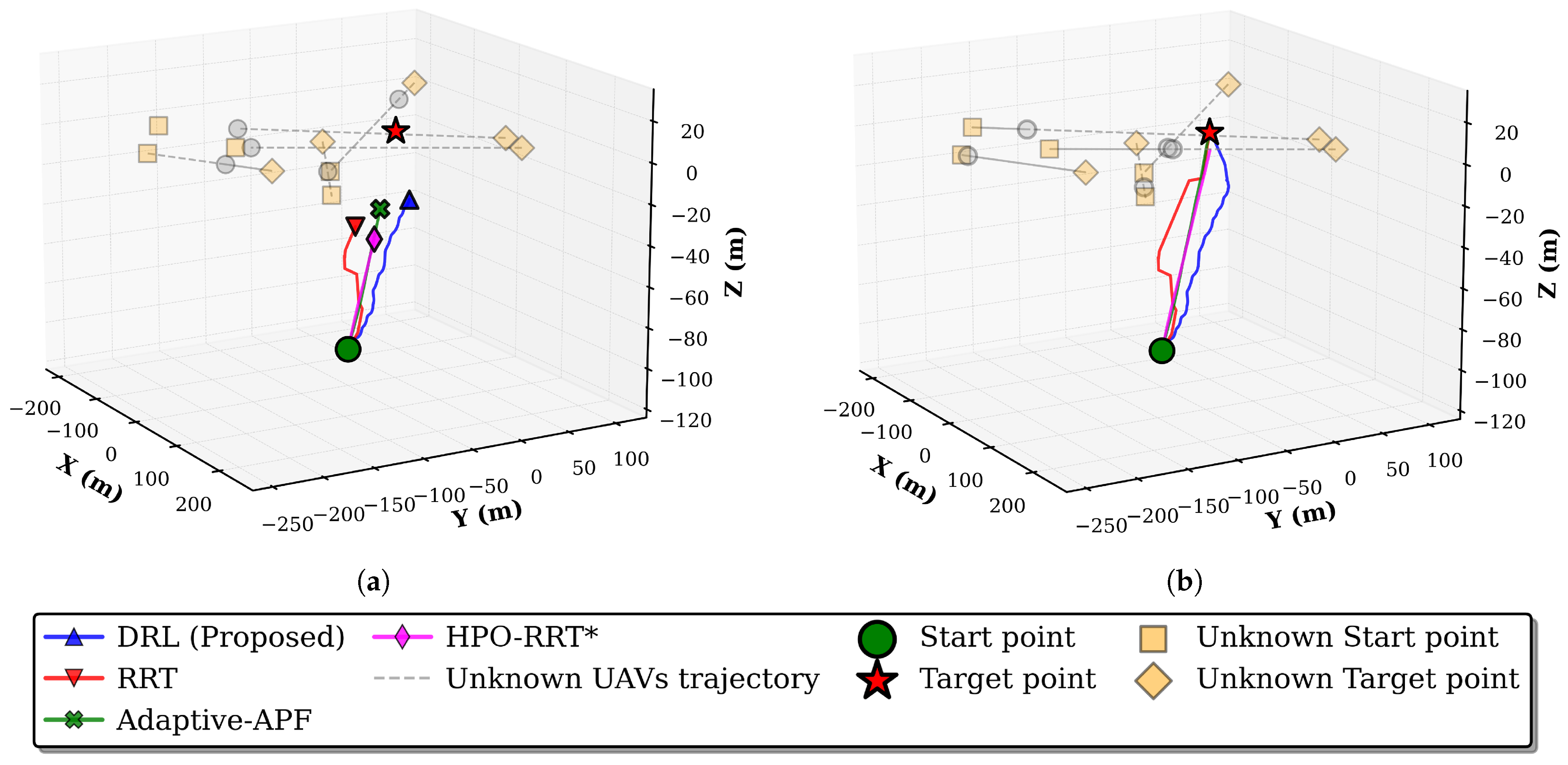
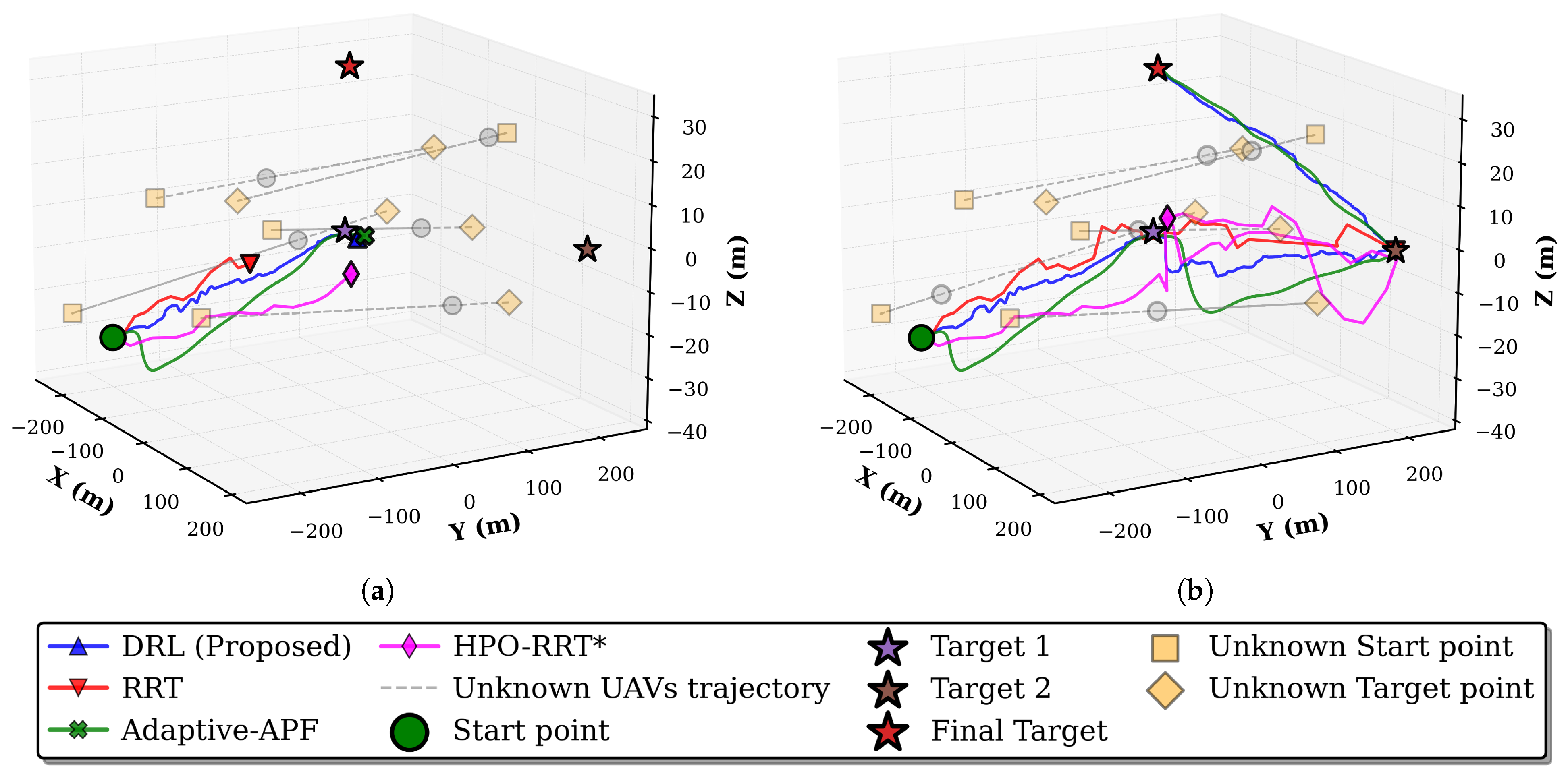
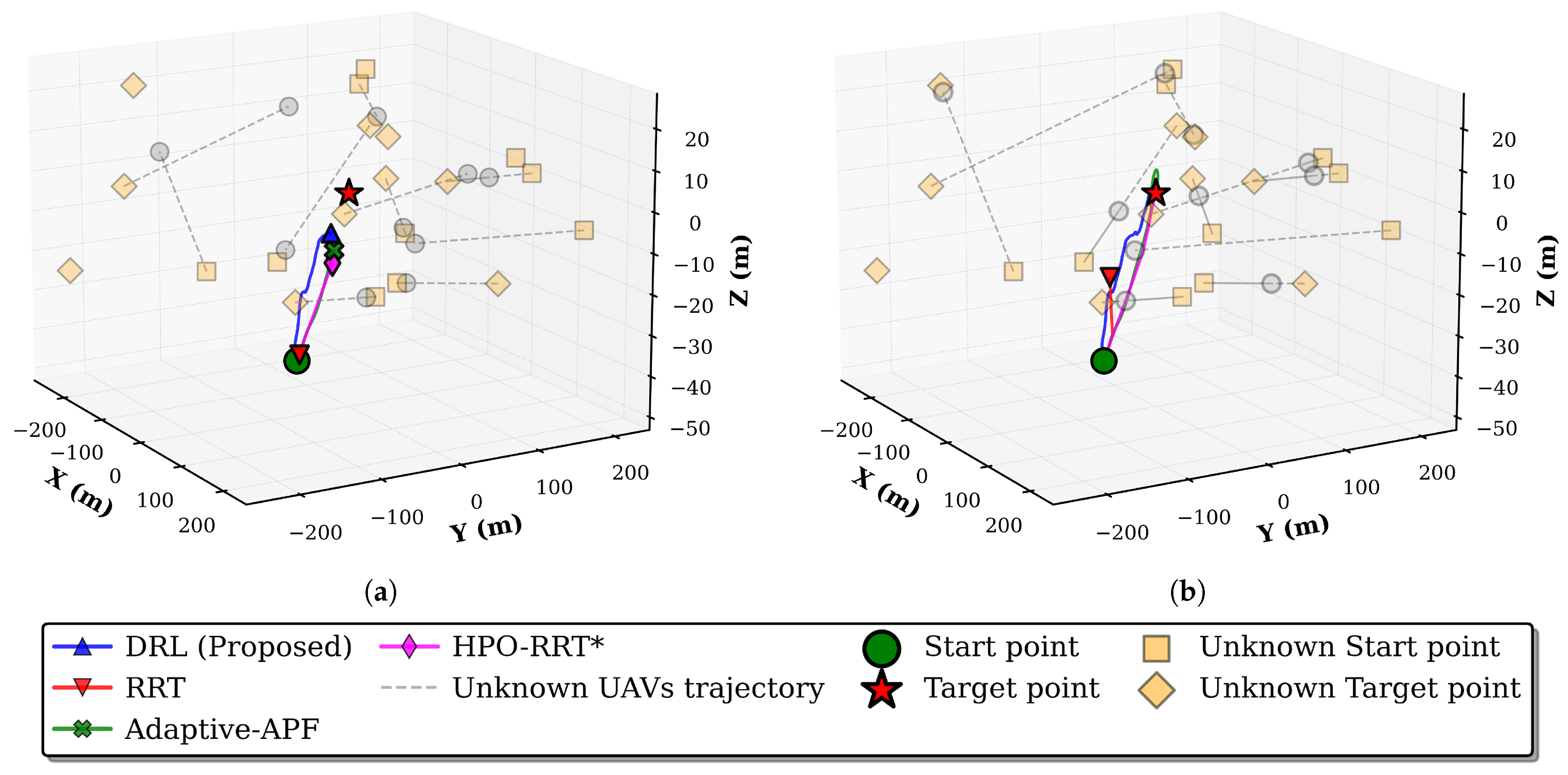
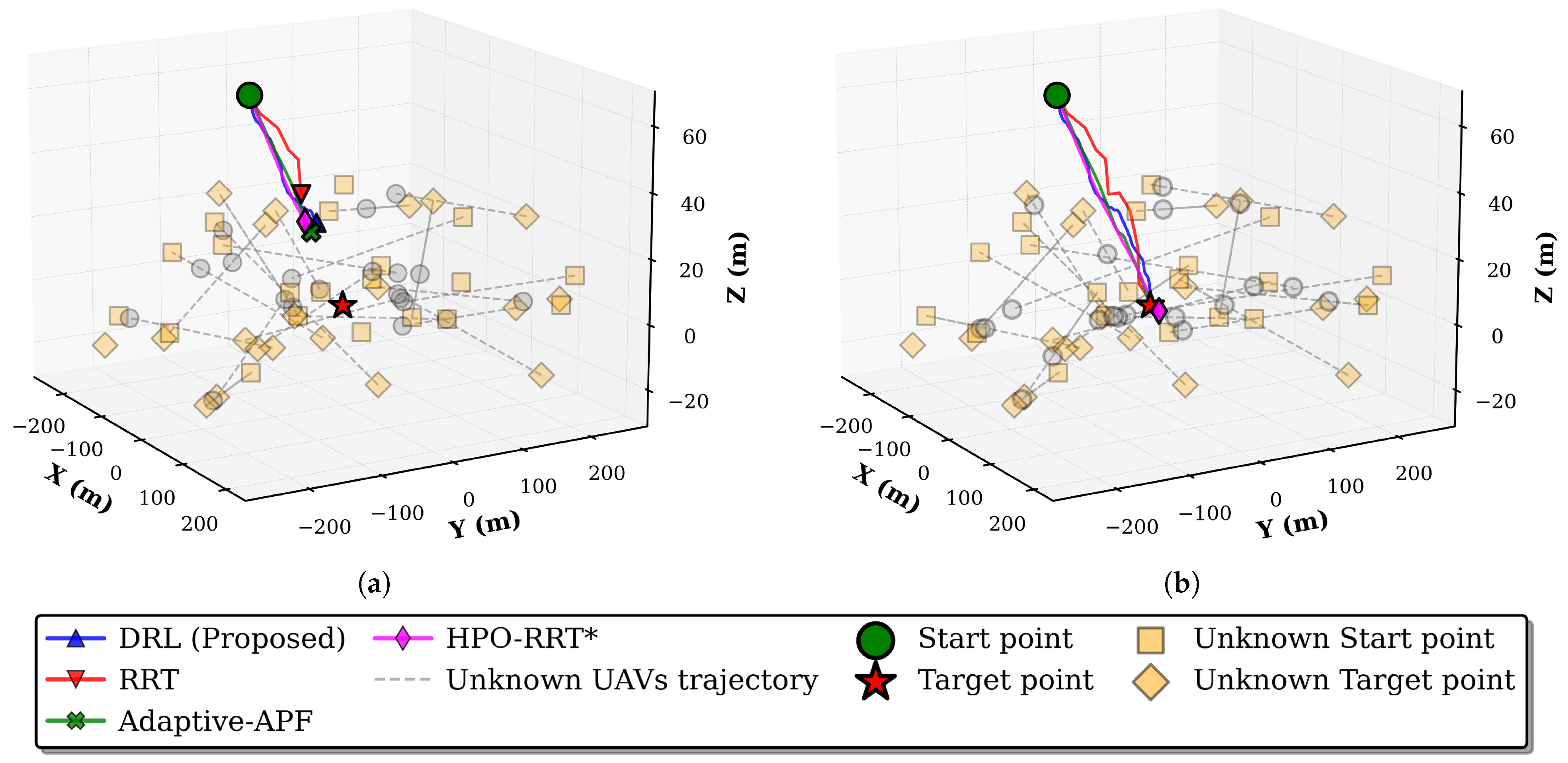
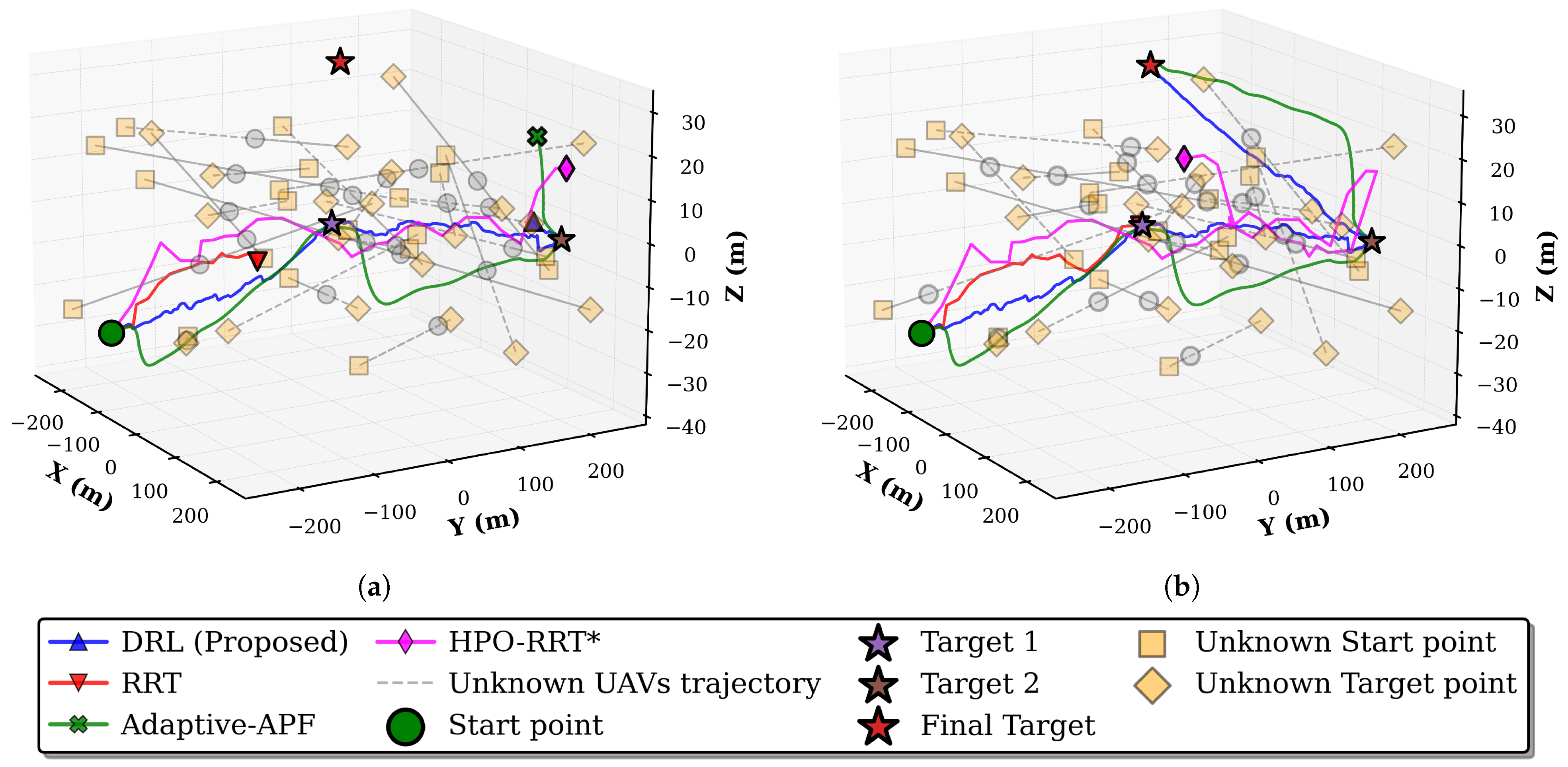
The simulation results for the single- and multi-target scenarios with 5, 10, and 20 unknown UAVs are presented in Figure 11, Figure 12, Figure 13, Figure 14, Figure 15 and Figure 16, respectively. In these figures, the trajectories generated by four methods are compared. The red line represents the trajectory generated by RRT, the purple line represents the trajectory generated by HPO-RRT*, the green line represents the trajectory generated by adaptive-APF, and the blue line represents the trajectory generated by the proposed method. The gray circle indicates the unknown UAVs, and the red star indicates the target point.
Figure 11a,b show the trajectories over time in the single-target scenario with five unknown UAVs. In this relatively low-density environment, all four methods successfully generated collision-free paths to the target. In contrast, differences among the methods can be observed in the multi-target scenario shown in Figure 12a,b. The proposed method generated smooth and near-optimal paths through gradual trajectory adjustments, whereas adaptive-APF exhibited maneuvers with wide detours caused by the repulsive forces of the unknown UAVs. Both HPO-RRT* and RRT showed abrupt trajectory changes, which can be attributed to the limited number of re-planning operations under real-time constraints. Consequently, neither method completed the path.
As shown in Figure 13 and Figure 14, the performance gap between the methods widens as complexity increases, reaching a medium-density environment with 10 unknown UAVs. In Figure 13b and Figure 14b, the proposed method consistently maintained smoother trajectories while effectively avoiding dynamic obstacles. By contrast, adaptive-APF was affected by the combined repulsive forces from multiple unknown UAVs, leading to more inefficient trajectories. Although HPO-RRT* can find an optimal path in single-target scenarios, it failed to generate feasible paths in multi-target scenarios, thereby exposing its inefficiency. RRT also failed to generate feasible paths in both scenarios due to the increased complexity of the environment.
The high-density environment with 20 unknown UAVs, shown in Figure 15 and Figure 16, represents a significant increase in complexity compared to the previous scenarios. In this environment, the proposed method enabled the agent to navigate through densely populated obstacle regions with smooth and consistent trajectories. Although adaptive-APF succeeded in completing paths, its performance was degraded by the increased number of dynamic obstacles, resulting in less efficient trajectories. In contrast, HPO-RRT* and RRT produced highly inefficient trajectories, struggling to adapt to the complex environment. These results demonstrate the robustness and scalability of the proposed method for navigation in complex and dynamic environments.
For a comprehensive evaluation, the simulation results were analyzed based on the average path length and path planning success rate. In this analysis, the proposed method was compared with adaptive-APF, HPO-RRT*, RRT, and a gravitational enhanced particle swarm optimization (GEPSO) algorithm [15]. As GEPSO relies on iterative pre-optimization under predetermined environmental settings, it was compared solely in terms of path length and success rate. The presented results, as summarized in Table 3 and Table 4, represent the mean values obtained from 500 simulations for each scenario, with the number of unknown UAVs set to [5, 10, 20].
Table 3 presents the path lengths of each method, with deviations from the optimal path shown in parentheses. In the single-target scenario, RRT exhibited the shortest average path length of 171.13 m, followed by the proposed method with 172.37 m, HPO-RRT* with 176.70 m, adaptive-APF with 193.41 m, and GEPSO with 217.43 m. In the multi-target scenario, the proposed method achieved the shortest average path length of 971.38 m, followed by HPO-RRT* with 1046.44 m, adaptive-APF with 1092.13 m, and GEPSO with 1277.83 m. RRT could not find a feasible path in this scenario. As shown in Table 4, the proposed method achieved success rates of 98.27% and 99.40% in the single- and multi-target scenarios, respectively. GEPSO achieved a success rate of 97.41% in the single-target scenario, only 0.8% below the proposed method, but declined to 87.83% in the multi-target scenario. Adaptive-APF reached a consistent success rate of approximately 89% in both scenarios. By contrast, HPO-RRT* achieved a 43.18% success rate in the single-target scenario but only 0.4% in the multi-target scenario. RRT demonstrated poor performance in both scenarios, with a success rate of only 3.8% in the single-target scenario, and could not complete the path in the multi-target scenario.
In a simple environment, the proposed and comparative methods can perform path planning toward the target. However, with an increasing number of unknown UAVs, the proposed method outperformed the comparative methods in terms of path length and success rate. The RRT and HPO-RRT*, based on random sampling, reached the midpoint but failed to reach the target due to the repeated collisions during the re-planning process. Adaptive-APF and GEPSO often select inefficient paths because they generate conservative paths to avoid collisions. In comparison, the proposed DRL method outperformed in path planning by identifying complex environmental states and selecting strategies that maximize rewards while appropriately maintaining target direction and safety. Therefore, the proposed method is demonstrated to be a robust approach capable of ensuring both reliability and efficiency in path planning under complex and dynamic environments.

6. Conclusions

A novel DRL-based method for path planning and collision avoidance was proposed to address realistic constraints in dynamic and complex environments where GPS is denied. The proposed method demonstrated that effective path planning is possible without GPS coordinates by estimating the UAV’s distance using only RSS without additional costly sensors. Furthermore, by controlling the attitude of the UAV, an efficient and smooth flight path can be generated. The core contribution of the proposed method is that the DRL agent successfully learned to avoid unknown threats and find an optimal path to the target point, despite the inherent uncertainties of RSS signals, noise, and interference properties. Through simulations, the proposed method was quantitatively shown to exhibit superior performance compared to existing methods in terms of path efficiency and robustness. In particular, it maintained a low collision rate even in high-density scenarios with an increasing number of unknown UAVs, suggesting its applicability in congested airspace.
Future research is necessary to further enhance the practicality of the proposed framework. First, the framework needs to be extended to a complex channel model that includes realistic signal distortions, such as multipath fading that can occur in real-world environments, to learn a more robust policy. In addition, simulations should also consider unknown UAVs with more complex, nonlinear trajectories instead of the current linear paths. Furthermore, enabling the agent to handle dynamic targets is another important aspect, which would require developing a separate tracking system to estimate the target’s state in real time under GPS-denied conditions. Second, extending the current single-agent framework to a multi-agent framework could also maximize both safety and operational efficiency. Lastly, the integration of UAVs with low Earth orbit (LEO) satellites is expected to expand the scope of applications, such as swarm flight for multi-UAV collaboration and communication support.

Author Contributions

Conceptualization, K.K. and J.S.; methodology, K.K., J.S., and J.K. (Jeongho Kim); software, K.K.; validation, K.K., S.L., and J.K. (Jinwook Kim); formal analysis, K.K., B.H., and Y.S.; investigation, K.K. and J.S.; resources, K.K. and M.L.; data curation, K.K. and S.K.; writing—original draft preparation, K.K., J.S., and J.K. (Jinwook Kim); writing—review and editing, K.K., J.S., and J.K. (Jinwook Kim), J.K. (Jeongho Kim), Y.S., S.L., S.K., B.H., M.L., and J.K. (Jinyoung Kim); visualization, K.K.; supervision, J.K. (Jinyoung Kim); project administration, J.K. (Jinyoung Kim). All authors have read and agreed to the published version of the manuscript.

Funding

This research received no external funding.

Data Availability Statement

The data presented in this study are available on request from the author.

Acknowledgments

This work was partly supported by an Institute of Information and Communications Technology Planning and Evaluation (IITP) grant funded by the Ministry of Science and ICT (MSIT) (No. 2021-0-00892-005, “Research on Advanced Physical-Layer Technologies of Low-Earth Orbit (LEO) Satellite Communication Systems for Ubiquitous Intelligence in Space” and supported by the MSIT, Korea, under the ITRC (Information Technology Research Center) support program (IITP-2025-RS-2023-00258639) supervised by the IITP.

Conflicts of Interest

The authors declare no conflicts of interest.

References

  1. Debnath, D.; Vanegas, F.; Sandino, J.; Hawary, A.F.; Gonzalez, F. A Review of UAV Path-Planning Algorithms and Obstacle Avoidance Methods for Remote Sensing Applications. Remote Sens. 2024, 16, 4019. [Google Scholar] [CrossRef]
  2. Mcfadyen, A.; Mejias, L. A Survey of Autonomous Vision-Based See and Avoid for Unmanned Aircraft Systems. Prog. Aeosp. Sci. 2016, 80, 1–17. [Google Scholar] [CrossRef]
  3. Hossein Motlagh, N.; Taleb, T.; Arouk, O. Low-Altitude Unmanned Aerial Vehicles-Based Internet of Things Services: Comprehensive Survey and Future Perspectives. IEEE Internet Things J. 2016, 3, 899–922. [Google Scholar] [CrossRef]
  4. Wang, H.; Mao, W.; Eriksson, L. A Three-Dimensional Dijkstra’s Algorithm for Multi-Objective Ship Voyage Optimization. Ocean Eng. 2019, 186, 106131. [Google Scholar] [CrossRef]
  5. Huang, X.; Dong, X.; Ma, J.; Liu, K.; Ahmed, S.; Lin, J.; Qiu, B. The Improved A* Obstacle Avoidance Algorithm for the Plant Protection UAV with Millimeter Wave Radar and Monocular Camera Data Fusion. Remote Sens. 2021, 13, 3364. [Google Scholar] [CrossRef]
  6. LaValle, S.M. Rapidly-Exploring Random Trees: A New Tool for Path Planning. Annu. Res. Rep. 1998. Technical Report. Available online: https://api.semanticscholar.org/CorpusID:14744621 (accessed on 25 September 2025).
  7. Zhang, J.; An, Y.; Cao, J.; Ouyang, S.; Wang, L. UAV Trajectory Planning for Complex Open Storage Environments Based on an Improved RRT Algorithm. IEEE Access 2023, 11, 23189–23204. [Google Scholar] [CrossRef]
  8. Guo, Y.; Liu, X.; Jia, Q.; Liu, X.; Zhang, W. HPO-RRT*: A Sampling-Based Algorithm for UAV Real-Time Path Planning in a Dynamic Environment. Complex Intell. Syst. 2023, 9, 7133–7153. [Google Scholar] [CrossRef]
  9. Khatib, O. Real-Time Obstacle Avoidance for Manipulators and Mobile Robots. In Proceedings of the 1985 IEEE International Conference on Robotics and Automation, St. Louis, MO, USA, 25–28 March 1985; Volume 2, pp. 500–505. [Google Scholar] [CrossRef]
  10. Zhang, H.Y.; Lin, W.M.; Chen, A.X. Path Planning for the Mobile Robot: A Review. Symmetry 2018, 10, 450. [Google Scholar] [CrossRef]
  11. Mao, J.; Jia, Z.; Gu, H.; Shi, C.; Shi, H.; He, L.; Wu, Q. Robust UAV Path Planning with Obstacle Avoidance for Emergency Rescue. In Proceedings of the 2025 IEEE Wireless Communications and Networking Conference (WCNC), Milan, Italy, 24–27 March 2025; pp. 1–6. [Google Scholar] [CrossRef]
  12. Chen, Z.; Zhou, H.; Du, S.; Liu, J.; Zhang, L.; Liu, Q. Reinforcement Learning-Based Resource Allocation and Energy Efficiency Optimization for a Space-Air-Ground-Integrated Network. Electronics 2024, 13, 1792. [Google Scholar] [CrossRef]
  13. Mai, X.; Dong, N.; Liu, S.; Chen, H. UAV Path Planning Based on a Dual-Strategy Ant Colony Optimization Algorithm. Intell. Robot. 2023, 3, 666–684. [Google Scholar] [CrossRef]
  14. Zhang, M.; Han, Y.; Chen, S.; Liu, M.; He, Z.; Pan, N. A Multi-Strategy Improved Differential Evolution algorithm for UAV 3D trajectory planning in complex mountainous environments. Eng. Appl. Artif. Intell. 2023, 125, 106672. [Google Scholar] [CrossRef]
  15. Wu, J.; Sun, Y.; Bi, J.; Chen, C.; Xie, Y. A Novel Hybrid Enhanced Particle Swarm Optimization for UAV Path Planning. IEEE Trans. Veh. Technol. 2025, 74, 11806–11819. [Google Scholar] [CrossRef]
  16. Wang, C.; Zhang, S.; Ma, T.; Xiao, Y.; Chen, M.Z.; Wang, L. Swarm intelligence: A survey of model classification and applications. Chin. J. Aeronaut. 2025, 38, 102982. [Google Scholar] [CrossRef]
  17. Wang, X.; Wang, S.; Liang, X.; Zhao, D.; Huang, J.; Xu, X.; Dai, B.; Miao, Q. Deep Reinforcement Learning: A Survey. IEEE Trans. Neural Netw. Learn. Syst. 2024, 35, 5064–5078. [Google Scholar] [CrossRef]
  18. Zhang, Y.; Zhao, W.; Wang, J.; Yuan, Y. Recent Progress, Challenges and Future Prospects of Applied Deep Reinforcement Learning: A Practical Perspective in Path Planning. Neurocomputing 2024, 608, 128423. [Google Scholar] [CrossRef]
  19. Lei, X.; Zhang, Z.; Dong, P. Dynamic Path Planning of Unknown Environment Based on Deep Reinforcement Learning. J. Robot. 2018, 2018, 5781591. [Google Scholar] [CrossRef]
  20. Alibabaei, K.; Gaspar, P.D.; Assunção, E.; Alirezazadeh, S.; Lima, T.M.; Soares, V.N.G.J.; Caldeira, J.M.L.P. Comparison of On-Policy Deep Reinforcement Learning A2C with Off-Policy DQN in Irrigation Optimization: A Case Study at a Site in Portugal. Computers 2022, 11, 104. [Google Scholar] [CrossRef]
  21. Wang, J.; Zhao, Z.; Qu, J.; Chen, X. APPA-3D: An Autonomous 3D Path Planning Algorithm for UAVs in Unknown Complex Environments. Sci. Rep. 2024, 14, 1231. [Google Scholar] [CrossRef]
  22. Arafat, M.Y.; Alam, M.M.; Moh, S. Vision-Based Navigation Techniques for Unmanned Aerial Vehicles: Review and Challenges. Drones 2023, 7, 89. [Google Scholar] [CrossRef]
  23. Ouyang, X.; Zeng, F.; Lv, D.; Dong, T.; Wang, H. Cooperative Navigation of UAVs in GNSS-Denied Area With Colored RSSI Measurements. IEEE Sens. J. 2021, 21, 2194–2210. [Google Scholar] [CrossRef]
  24. Gu, S.; Yang, L.; Du, Y.; Chen, G.; Walter, F.; Wang, J.; Knoll, A. A Review of Safe Reinforcement Learning: Methods, Theories, and Applications. IEEE Trans. Pattern Anal. Mach. Intell. 2024, 46, 11216–11235. [Google Scholar] [CrossRef]
  25. Ebrahimi, D.; Sharafeddine, S.; Ho, P.H.; Assi, C. Autonomous UAV Trajectory for Localizing Ground Objects: A Reinforcement Learning Approach. IEEE. Trans. Mob. Comput. 2021, 20, 1312–1324. [Google Scholar] [CrossRef]
  26. Liu, Y.; Yang, Z. Location, Localization, and Localizability: Location-Awareness Technology for Wireless Networks; Springer: New York, NY, USA, 2011. [Google Scholar] [CrossRef]
  27. Singh, N.; Choe, S.; Punmiya, R. Machine Learning Based Indoor Localization Using Wi-Fi RSSI Fingerprints: An Overview. IEEE Access 2021, 9, 127150–127174. [Google Scholar] [CrossRef]
  28. Zafari, F.; Gkelias, A.; Leung, K.K. A Survey of Indoor Localization Systems and Technologies. IEEE Commun. Surv. Tutor. 2019, 21, 2568–2599. [Google Scholar] [CrossRef]
  29. Zekavat, R.; Buehrer, R.M. The Kalman Filter and Its Applications in GNSS and INS; Wiley-IEEE Press: Hoboken, NJ, USA, 2012; pp. 709–751. [Google Scholar] [CrossRef]
  30. Luo, C.; McClean, S.I.; Parr, G.; Teacy, L.; De Nardi, R. UAV Position Estimation and Collision Avoidance Using the Extended Kalman Filter. IEEE Trans. Veh. Technol. 2013, 62, 2749–2762. [Google Scholar] [CrossRef]
  31. Xiang, B.; Yan, F.; Zhu, Y.; Wu, T.; Xia, W.; Pang, J.; Liu, W.; Heng, G.; Shen, L. UAV Assisted Localization Scheme of WSNs Using RSSI and CSI Information. In Proceedings of the 2020 IEEE 6th International Conference on Computer and Communications (ICCC), Chengdu, China, 11–14 December 2020; pp. 718–722. [Google Scholar] [CrossRef]
  32. Kabiri, M.; Cimarelli, C.; Bavle, H.; Sanchez-Lopez, J.L.; Voos, H. A Review of Radio Frequency Based Localisation for Aerial and Ground Robots with 5G Future Perspectives. Sensors 2023, 23, 188. [Google Scholar] [CrossRef] [PubMed]
  33. Beard, R.W.; McLain, T.W. Small Unmanned Aircraft: Theory and Practice; Princeton University Press: Princeton, NJ, USA, 2012. [Google Scholar]
  34. Lee, T.; Leok, M.; McClamroch, N.H. Geometric Tracking Control of a Quadrotor UAV on SE(3). In Proceedings of the 49th IEEE Conference on Decision and Control (CDC), Atlanta, GA, USA, 15–17 December 2010; pp. 5420–5425. [Google Scholar] [CrossRef]
  35. Coates, E.M.; Fossen, T.I. Geometric Reduced-Attitude Control of Fixed-Wing UAVs. Appl. Sci. 2021, 11, 3147. [Google Scholar] [CrossRef]
  36. Yuan, X.; Xu, J.; Li, S. Design and Simulation Verification of Model Predictive Attitude Control Based on Feedback Linearization for Quadrotor UAV. Appl. Sci. 2025, 15, 5218. [Google Scholar] [CrossRef]
  37. Li, Y.; Tan, G. Attitude Control of Quadrotor UAV Using Improved Active Disturbance Rejection Control. Front. Comput. Intell. Syst. 2023, 5, 90–95. [Google Scholar] [CrossRef]
  38. Schulman, J.; Wolski, F.; Dhariwal, P.; Radford, A.; Klimov, O. Proximal Policy Optimization Algorithms. arXiv 2017, arXiv:1707.06347. [Google Scholar] [CrossRef]
  39. Chang, Z.; Deng, H.; You, L.; Min, G.; Garg, S.; Kaddoum, G. Trajectory Design and Resource Allocation for Multi-UAV Networks: Deep Reinforcement Learning Approaches. IEEE Trans. Netw. Sci. Eng. 2023, 10, 2940–2951. [Google Scholar] [CrossRef]
  40. Qi, C.; Wu, C.; Lei, L.; Li, X.; Cong, P. UAV Path Planning Based on the Improved PPO Algorithm. In Proceedings of the 2022 Asia Conference on Advanced Robotics, Automation, and Control Engineering (ARACE), Qingdao, China, 26–28 August 2022; pp. 193–199. [Google Scholar] [CrossRef]
  41. Andrychowicz, M.; Raichuk, A.; Stańczyk, P.; Orsini, M.; Girgin, S.; Marinier, R.; Hussenot, L.; Geist, M.; Pietquin, O.; Michalski, M.; et al. What Matters In On-Policy Reinforcement Learning? A Large-Scale Empirical Study. In Proceedings of the 9th International Conference on Learning Representations (ICLR), Vienna, Austria, 3–7 May 2021. [Google Scholar]
  42. Moro, S.; Teeda, V.; Scazzoli, D.; Reggiani, L.; Magarini, M. Experimental UAV-Aided RSSI Localization of a Ground RF Emitter in 865 MHz and 2.4 GHz Bands. In Proceedings of the 2022 IEEE 95th Vehicular Technology Conference: (VTC2022-Spring), Helsinki, Finland, 19–22 June 2022; pp. 1–6. [Google Scholar] [CrossRef]
  43. Li, H.; Duan, X.L. Research on Adaptive Artificial Potential Field Obstacle Avoidance Technology for Unmanned Aerial Vehicles in Complex Environments. Int. J. Wirel. Mob. Comput. 2025, 29, 10072641. [Google Scholar] [CrossRef]
Figure 1. Schematic diagram of proposed system model.
Electronics 14 03844 g001
Figure 2. Schematic diagram of EKF algorithm for RSS-based distance estimation.
Electronics 14 03844 g002
Figure 3. UAV kinematic model: (a) UAV orientation represented by yaw and pitch angles, (b) heading direction in the z-axis, (c) ascent and descent along the y-axis.
Electronics 14 03844 g003
Figure 4. Schematic diagram of the proposed DRL-based path planning and collision avoidance framework.
Electronics 14 03844 g004
Figure 5. Three-dimensional visualization of agent’s action space.
Electronics 14 03844 g005
Figure 6. UAV safety zones for collision avoidance.
Electronics 14 03844 g006
Figure 7. Architecture of the actor–critic DRL network used in PPO.
Electronics 14 03844 g007
Figure 8. Visualization of 3D simulation environments with 20 unknown UAVs: (a) single-target scenario, (b) multi-target scenario.
Electronics 14 03844 g008
Figure 9. Comparison of the UAV’s 3D flight path by reward function component.
Electronics 14 03844 g009
Figure 10. Comparison of the average maintenance distance with unknown UAVs in single- and multi-target scenarios for the proposed DRL method.
Electronics 14 03844 g010
Figure 11. Comparison of 3D trajectories for 5 unknown UAVs in the single-target scenario: (a) developing and (b) completed trajectories.
Electronics 14 03844 g011
Figure 12. Comparison of 3D trajectories for 5 unknown UAVs in the multi-target scenario: (a) developing and (b) completed trajectories.
Electronics 14 03844 g012
Figure 13. Comparison of 3D trajectories for 10 unknown UAVs in the single-target scenario: (a) developing and (b) completed trajectories.
Electronics 14 03844 g013
Figure 14. Comparison of 3D trajectories for 10 unknown UAVs in the multi-target scenario: (a) developing and (b) completed trajectories.
Electronics 14 03844 g014
Figure 15. Comparison of 3D trajectories for 20 unknown UAVs in the single-target scenario: (a) developing and (b) completed trajectories.
Electronics 14 03844 g015
Figure 16. Comparison of 3D trajectories for 20 unknown UAVs in the multi-target scenario: (a) developing and (b) completed trajectories.
Electronics 14 03844 g016
Table 1. Definition of the action space for the UAV agent.
ActionsYaw ( ψ t / ψ t ) Pitch ( θ t / θ t ) Description
Stop ψ t = 0.0 θ t = 0.0 Set velocity v to 0.
Forward ψ t ψ t 1 θ t θ t 1 Maintain direction.
Yaw right ψ t = 180.0 θ t θ t 1 Horizontal right turn.
Yaw left ψ t = + 180.0 θ t θ t 1 Horizontal left turn.
Pitch up ψ t ψ t 1 θ t = 0 Altitude ascent.
Pitch down ψ t ψ t 1 θ t = 0 Altitude descent.
Attitude control 30.0 ψ t 30.0
ψ t ψ t 1 + ψ t
15.0 θ t 15.0
θ t θ t 1 + θ t
Direction changed by u t .
Table 2. Simulation parameters.
ParameterValue
UAV agent’s velocity v1.0 (m/s)
RSS sensing range d sr 100.0 (m)
Collision avoidance range d cz 50.0 (m)
Collision threshold d dz 5.0 (m)
Number of unknown UAV[5, 10, 20]
Unknown UAV’s velocity2.0–10.0 (m/s)
Path loss exponent η 2.2–4.0
r direction weight c 1 0.7
r safe weight c 2 1.3
Clip factor ϵ 0.2
Actor learning rate 3 × 10 5
Critic learning rate 1 × 10 4
Table 3. Comparison of average path lengths in both single- and multi-target scenarios.
MethodologySingle-Target Scenario (m)Multi-Target Scenario (m)
Baseline (Optimal path)164.54932.51
Proposed172.37 (+7.83)971.38 (+38.87)
Adaptive-APF193.41 (+28.87)1092.13 (+159.62)
HPO-RRT*176.70 (+12.16)1046.44 (+113.93)
RRT171.13 (+6.59)No path found
GEPSO217.43 (+52.89)1277.83 (+345.32)
Table 4. Comparison of path planning success rate in both single- and multi-target scenarios.
MethodologySingle-Target Scenario (%)Multi-Target Scenario (%)
Proposed98.2799.40
Adaptive-APF89.0789.43
HPO-RRT*43.180.4
RRT3.8Not applicable
GEPSO97.4187.83
Disclaimer/Publisher’s Note: The statements, opinions and data contained in all publications are solely those of the individual author(s) and contributor(s) and not of MDPI and/or the editor(s). MDPI and/or the editor(s) disclaim responsibility for any injury to people or property resulting from any ideas, methods, instructions or products referred to in the content.