Article

RIS-Assisted Backscatter V2I Communication System: Spectral-Energy Efficient Trade-Off

1
School of Electronic and Information Engineering, Shenyang Aerospace University, Shenyang 110136, China
2
Liaoning Provincial Key Laboratory of Aerospace Information Perception and Intelligent Processing, Shenyang 110136, China
*
Author to whom correspondence should be addressed.
Electronics 2025, 14(19), 3800; https://doi.org/10.3390/electronics14193800
Submission received: 29 August 2025 / Revised: 14 September 2025 / Accepted: 23 September 2025 / Published: 25 September 2025

Abstract

In this paper, an energy efficiency (EE)–spectral efficiency (SE) trade-off scheme is investigated for the distributed reconfigurable intelligent surface (RIS)-assisted backscatter vehicle-to-infrastructure (V2I) communication system. Firstly, a multi-objective optimization framework balancing EE and SE is established using the linear weighting method, and the quadratic transformation is utilized to recast the optimization problem as a strictly convex problem. Secondly, an alternating optimization (AO) approach is applied to partition the original problem into two independent subproblems of the BS and RIS beamforming, which are, respectively, designed by the weighted minimization mean-square error (WMMSE) and the Riemannian conjugate gradient (RCG) algorithms. Finally, according to the trade-off factor, the power reflection coefficients of backscatter devices (BDs) are dynamically optimized with the BS beamforming vectors and RIS phase shift matrices, considering their activation requirements and the vehicle minimum quality of service (QoS). The simulation results verify the effectiveness of the proposed algorithm in simultaneously improving SE and the EE in practical V2I applications through rational optimization of the BD power reflection coefficient.

1. Introduction

Vehicle-to-infrastructure (V2I) is a critical component of vehicle-to-everything (V2X) technology, which is expected to facilitate high-speed, low-delay, and low-cost consumption interactions between vehicles and surrounding infrastructure for intelligent communication in the era beyond fifth generation (B5G) and sixth generation (6G) wireless advancements [1]. The V2X networks provide internet connectivity to vehicles, enabling access to real-time road data beyond their immediate sensor range, which is essential for intelligent automotive services. As an integral subsystem of V2X, V2I communications are pivotal for establishing the last-mile wireless link between roadside units (RSUs) and vehicles [2]. The existing research has extensively investigated the energy efficiency (EE) and spectral efficiency (SE) of V2I communication systems. In [3], a beam alignment algorithm based on vehicle position information is proposed to achieve fast beam alignment, which effectively improves the transmission rate of the mmWave V2I system. In the multi-cell downlink V2I network, a joint power control and user scheduling problem is investigated in [4] to maximize the sum-rate of the network. In [5], a method is proposed to maintain finite service time for the entire vehicle, by utilizing V2X and V2I communications, which jointly controls offloading policy and computing resources to minimize energy consumption. Through coordinated improvements in beam steering, spectrum/power allocation, and edge computing control, existing studies substantially elevate V2I system capabilities across rate, scalability, and EE dimensions. However, the substantial growth of the number of RSUs involved in V2I communication system poses a significant EE challenge.
Recently, backscatter communication (BackCom) has been a low-power and low-cost candidate technology for V2I transmission solutions in the B5G or 6G era, in which backscatter devices (BDs) can utilize the surrounding radio frequency (RF) signals to achieve wireless energy collection for signal modulation and reflection communication [6,7,8,9,10]. Over the past few years, the performance of backscatter V2I communication scenarios have been extensively investigated. For example, a V2I backscattering protocol is proposed in [6] for secure communication between a BD-equipped vehicle and a monostatic reader-equipped RSU. This green, low-cost, and sustainable protocol enables EE V2I communication. In [7], the closed-form ergodic capacity expression for ambient backscatter communication (AmBC)-assisted vehicle-to-vehicle (V2V) communication systems under double-Rayleigh fading channels is derived, which employs Gauss–Chebyshev and Gauss–Laguerre quadrature for precise computation. In [8], to maximize the sum-rate of a backscatter V2X system, a resource allocation strategy utilizing an alternating optimization (AO) algorithm is developed. In [9], a joint optimization problem of power allocation at BS and RSUs has been formulated to maximize the minimum achievable rate of non-orthogonal multiple access (NOMA)-enabled backscatter V2I networks, in which a BD is used to assist the communication between the vehicle and RSU. In [10], an optimization framework for EE transmission in AmBC-V2I networks is proposed, subject to the individual quality of service constraints, which simultaneously minimizes the total transmit power of the V2I network by optimizing the power allocation at the BS and BD power reflection coefficients.
Although BackCom technology demonstrates some EE advantages when applied to V2I communication systems, its passive architecture fundamentally constrains the SE and makes it struggle to support the V2I scenarios which generally require high-throughput and robust data transmission. In fact, the energy harvesting efficiency and information transmission coverage of BDs may be limited by the double-fading effect of the wireless channel [11], and they have to operate subject to a minimum RF power requirement for self-activation. When the activation threshold of BDs fails to be reached, it will lead to an unreliable V2I communication range [12]. In response, many methodologies [13,14,15,16,17,18,19,20,21] have been explored to overcome SE and activation threshold constraints in the BackCom system. For the high efficiency harvesting of ambient RF energy, the development of multiband/broadband rectifiers has been pursued [13,14,15,16]. Such rectifiers function by covering multiple frequency bands to aggregate the power from mixed signals and convert it to a direct current. The approach in [17,18,19,20] focuses on energy beamforming and expanding the emitter’s antenna array, which collectively increase the power delivered to the BD and extend the communication range. Ref. [21] improves the BD reading range and energy harvest efficiency by assigning transmission power to favorable frequency channels (those with high gain or low path loss), or by enhancing the peak-to-average power ratio of the beacon signals. However, due to the limited processing capability and power constraints of BDs, the SE of V2I systems still cannot be fully enhanced through the integration of BackCom. Moreover, from another perspective, merely deploying passive BDs in traditional V2I networks, without fundamentally addressing the energy consumption issue of the RSUs themselves, cannot eliminate the high energy consumption caused by the increasing number of RSUs. These persistent challenges highlight the critical need for developing a novel solution that could ensure SE and EE in backscatter V2I communication systems.
Reconfigurable Intelligent Surfaces (RISs) have recently garnered significant interest from industrial and academic communities, owing to their potential in enabling the intelligent reconfiguration of the wireless propagation environment. This promising technology has already found diverse applications across various wireless communication systems [22]. The similar reflection mechanism to BackCom enables RISs to dynamically adjust to the wireless channel conditions and to address the severe double-fading attenuation in the BackCom network [22]. Due to its prominent properties, there has been a growing focus on RIS-assisted backscatter V2I communications in recent years. In [23], to handle the weakness of SE which is caused by weak backscatter signals and the presence of strong direct interference signals, RISs are deployed between BDs and vehicles to facilitate information transmission in the AmBC-V2I environment. The BD, which operates on the environmental power source combined with the battery-powered RSU, could overcome the energy consumption challenge of RSUs. In [24], RISs act as BDs to send road information by backscattering the signals. The introduced RIS-assisted backscatter V2I system combines RISs and BDs as RSUs to realize low-power transmission; an AO algorithm is proposed to maximize the collected data volume. In [25], a framework for V2I communication networks is proposed by integrating RISs with BDs. The detection matrix and transmission power at the vehicle, as well as the RIS phase shift, are jointly designed based on an AO algorithm to boost the total weighted sum-rate of the system. A framework for RIS-assisted backscatter V2I communication in the presence of eavesdropper networks is presented in [26], which exploits transmitting and reflectivity properties for secure transmission to maximize the secrecy rate. Although the introduction of RISs can effectively improve the SE of the backscatter V2I system, the actual incident power demand and effect of BDs were not considered in [23,24,25,26]. As rigorously demonstrated in [27,28], after propagating through double-fading channels and being affected by signal interference, the power from the signal source may fall below the BD activation. Furthermore, in [29], it has been proven that joint optimization of the BD power reflection coefficient and RIS phase shifts can suppress the impact of double-fading channels, thereby achieving sum-rate maximization in RIS-BackCom systems.
Based on the literature, we can conclude that most of the existing work in RIS-assisted backscatter V2I systems is centered on the enhancement of individual SE or EE [23,24,25,26]. Actually, SE may sometimes be compromised to enhance EE. Since the enhancement of SE or EE alone cannot meet the diverse requirements in parctical V2I communication scenarios, it is necessary to find effective methods that can take into account both. As far as we know, although many studies have balanced EE and SE in the traditional RIS-assisted wireless communication system [30,31,32], the balance between EE and SE has yet to be thoroughly explored in the context of RIS-BackCom for V2I communications. Existing studies typically presume that the incident power at a BD exceeds its activation threshold and have largely neglected its influence on the performance of V2I systems. Considering the practical operational requirements of BDs, dynamic optimization of the BD power reflection coefficient is equally critical, as this parameter directly governs the BD activation threshold while simultaneously influencing the achievable EE and SE of the system. Moreover, in the existing literature, most backscatter V2I systems, which are assisted by only a single RIS [23,26], can see their deployment benefits obliterated by continuous changes in dynamic environments when the associated link is obstructed. In such conditions, the deployment of distributed RISs provides higher spatial degrees of freedom with low-correlation channels, supporting more parallel data streams, and boosts the SE of the dynamic V2I communication system through independent RIS allocation or phase adjustment [33]. Motivated by these findings, we propose an EE-SE trade-off framework which incorporates BD power reflection coefficients into the joint optimization scheme for the distributed RIS-assisted backscatter V2I communication system.
In consideration of the aforementioned motivation and challenges, unlike previous works in [23,24,25], a multi-objective optimization scheme is proposed, which simultaneously optimizes the vehicle data collection volume and the EE for the distributed RIS-assisted backscatter V2I system. The main contributions of this paper are summarized as follows:
  • To attain a balance between EE and SE for the distributed RIS-assisted backscatter V2I system, a novel multi-objective optimization framework is established for the first time using the linear weighting method. The optimization problem is transformed into a strictly convex problem by quadratic transformation. Then, an AO approach is applied to partition the original problem into two independent subproblems. The weighted minimization mean-square error (WMMSE) algorithm and the Riemannian conjugate gradient (RCG) algorithm are, respectively, used for the BS beamforming vectors and RIS phase shift matrices and converge rapidly through iterative optimization.
  • Existing research predominantly overlooks the critical impact of the BD power reflection coefficient on RIS-assisted backscatter V2I system performance. To address this gap, this paper presents, to the best of our knowledge, the first investigation of its impact on both EE and SE performance in such systems. By jointly designing the beamforming for the BS and RIS, the BD power reflection coefficients are dynamically optimized subject to their activation requirements and the vehicle minimum QoS, thereby further enhancing the EE-SE trade-off performance.
  • Unlike the conventional single RIS-assisted backscatter V2I communication system, distributed RIS is used in this paper to provide a high-quality link between the BS and BD, which overcomes the limitations of single RIS, such as high channel correlation and restricted beam steering range. It enables more parallel transmissions, thereby supporting a greater number of BDs and boosting the overall EE and SE performance of the backscatter V2I system. This distributed architecture also facilitates continuous signal transmission, which is crucial for the dynamic and mobile nature of V2I communication.
The remainder of this paper is structured below. A distributed RIS-assisted backscatter signal model in a V2I communication system is presented in Section 2. The multi-objective optimization framework is established by the linear weighting method in Section 3. A beamforming scheme which jointly optimizes the BS beamforming vector, RIS phase shift matrix, and BD power reflection coefficient is proposed in Section 4. The feasibility of the proposed algorithm is proven by the simulation results in Section 5. Finally, the conclusions are summarized in Section 6.

2. System Model

Consider the distributed RIS-assisted BackCom system in a V2I scenario which is shown in Figure 1. The BS is modeled as a uniform linear array (ULA) which is equipped with M antennas, K BDs which have a single antenna, I vehicles which act as the backscatter receivers (BRs) equipped with a single antenna, and two RISs modeled as a uniform planar array (UPA) and each equipped with N passive reflecting elements. In addition, BackCom period T B is equally divided into K time slots; the wireless channel remains invariant throughout the BackCom period. The BRs adopt the time division multiple access (TDMA) mechanism to receive RF signals. Each BD selects a single time slot for data transmission to the vehicle via backscattering. Specifically, the kth BD performs backscatter in the kth time slot while harvesting energy solely in the other (K-1) time slots.
The channels from BS to RIS1 and RIS2 are represented by H s 1 C M × N and H s 2 C M × N , respectively; the channels from RIS1 and RIS2 to the kth BD are, respectively, represented by H r 1 , k C N × 1 and H r 2 , k C N × 1 ; and the channel from the kth BD to ith BR is represented by h bk , i C 1 × 1 . Perfect channel state information (CSI) is presumed to be available for every channel discussed above. The phase shift matrices of RIS1 and RIS2 are defined as diagonal matrices Θ 1 = diag θ 1 , 1 , , θ n , 1 , , θ N , 1 and Θ 2 = diag θ 2 , 2 , , θ n , 2 , , θ N , 2 , respectively, where θ n , 1 = e j φ n , 1 and θ n , 2 = e j φ n , 2 are the phases of the nth reflecting element on the RIS.
Denote the BS transmit symbol by x = w v , where w = [ w 1 , ,   w K ] is the transmit beamforming vector, w k C M × 1 ; and v = [ v 1 ; ; v K ] is the BS transmit data symbol, v k = [ v k , 1 , , v k , I ]. The direct link between BS and BD suffers from deep fading and shadowing, so the BS-RIS-BD link can be mainly considered and the direct link ignored. Therefore, the received signal of ith BR at the kth time slot can be expressed as
y b k , i = h b k , i a k ( H 1 + H 2 ) x k , i s i + j = 1 , j i I h b k , j a k ( H 1 + H 2 ) x k , j s j + z i
where x k , i = w k v k , i , s = [ s 1 , , s I ] is the BD backscattered signal. a k ( 0 , 1 ) is the power reflection coefficient of BD and z i CN ( 0 , σ 0 2 ) represents additive white gaussian noise (AWGN) at BR. The channel coefficient matrix of BS-RIS-BD links H 1 , H 2 and BD-BR link h b k , i can be, respectively, expressed as
H 1 = H s 1 Θ 1 H r 1 , k = S F r 1 , k S F s 1 P L BRD h s 1 Θ 1 h r 1 , k
H 2 = H s 2 Θ 2 H r 2 , k = S F r 2 , k S F s 2 P L BRD h s 2 Θ 2 h r 2 , k
h b k , i = S F b k , i P L DR h ¯ b k , i
where h s 1 , h r 1 , k , h s 2 , and h r 2 , k are the small-scale fading matrices. A three-dimensional (3D) geometry-based stochastic model (GBSM) for a backscattering V2I system employing practical discrete RISs is introduced in this paper [34]. S F r 1 , k , S F r 2 , k , S F s 1 , S F s 2 , and S F b k , i are characterized by log normal distributions representing the shadowing fading in different sub-channels. P L DR characterizes the path loss in the sub-channel linking BD and BR and P L BRD characterizes the path loss of the BS-RIS-BD cascaded channel. Regarding the former, we utilize the path loss model from the established QuaDRiGa channel framework as
P L DR [ d B ] = A log 10 d [ km ] B C log 10 f [ GHz ]
where A , B , and  C are variables specified by the communication environment. The BS-RIS-BD sub-channel path loss is given by
P L BRD = δ I x δ I y λ 2 64 π 3 x = 1 N x y = 1 N y 1 r x , y t r x , y r 2
where N x and N y specify the number of RIS elements in the horizontal and vertical dimensions, respectively; δ I x and δ I y represent the inter-element spacing along both dimensions of the RIS; r x , y t , r x , y r are the distances between the BS and BD with each element on the RIS; and λ is the wavelength.
The entries of the small-scale fading matrix h s 1 are designated as h q r , s 1 ( t , τ ) , which represents the channel coefficients between the qth antenna on the BS and the rth element on RIS 1 at time instant t . It is calculated as
h q r , s 1 ( t , τ ) = C C + 1 h q r , s 1 L + 1 C + 1 h q r , s 1 N ( t , τ )
Similarly, we can obtain the h q r , s 2 ( t , τ ) , h q r , r 1 , k ( t , τ ) , h q r , r 2 , k ( t , τ ) , and h ¯ b k , i ( t , τ ) . To simplify the analysis, this paper takes h q r , s 1 ( t , τ ) as an example. Obviously, the resultant expression is derived by combining two weighted elements: the non-line-of-sight (NLoS) component and the line-of-sight (LoS) component. The weighting coefficients for these elements are governed by the Rician factor C . The LoS term is expressed as
h q r , s 1 L ( t , τ ) = e j 2 π f c τ q r , s 1 L ( t ) δ ( τ τ q r , s 1 L ( t ) )
where τ q r , s 1 L ( t ) = D q r , s 1 ( t ) / c is the propogation delay of the LoS component.
The NLoS component is generated through a Gaussian distributed scatterer which is denoted by
h q r , s 1 N ( t , τ ) = n = 1 N q r , s 1 ( t ) m n = 1 M n P q r , s 1 , m n ( t ) e j 2 π f c τ q r , m n ( t ) · δ ( τ τ q r , s 1 , m n N ( t ) )
where m n is the mth scatterer in the nth cluster, N q r , s 1 ( t ) corresponds to the total cluster count at time instant t, P q r , s 1 , m n ( t ) is the power of the ray, δ ( · ) denotes the Dirac delta function, and τ q r , s 1 , m n N ( t ) represents the wireless link’s propagation delay, which is calculated as
τ q r , s 1 , m n N ( t ) = ( | | d q , m n [ I q B + 0 t ( v B ( t ) v A n ( t ) d t ) ] | | + | | d r , m n [ I r I + 0 t ( v Z n ( t ) d t ) ] | | ) / c + τ n , s 1 v
where c is the light speed. τ n , s 1 v represents the virtual link delay. | | · | | means the Frobenius norm. d q , m n and d r , m n are calculated as
d q , m n = d q , m n [ c o s ϕ E , m n , q c o s ϕ A , m n , q , c o s ϕ E , m n , q s i n ϕ A , m n , q , s i n ϕ A , m n , q ]
and
d r , m n = d r , m n [ c o s ϕ E , m n , r c o s ϕ A , m n , r , c o s ϕ E , m n , r s i n ϕ A , m n , r , s i n ϕ A , m n , r ]
where ϕ A , m n , q and ϕ E , m n , q denote the azimuth angle of departure (AAoD) and elevation angle of departure (EAoD), respectively, for the mth ray at the initial time. Correspondingly, ϕ A , m n , r and ϕ E , m n , r are the azimuth angle of arrival (AAoA) and the elevation angle of arrival (EAoA) of the ray received by the center of the RIS.
BD performs energy harvesting (EH) and data transmission simultaneously via the power-splitting mode [28]. Each task takes a fraction of the incident RF power on the BD. The incident power at the BD is expressed as
P T = k = 1 K | | w k | | 2 H 1 + H 2 2
where k = 1 K | | w k | | 2 is the BS transmit power, and BD backscatters a k P T of the received RF power and absorbs ( 1 a k ) P T for EH. So the received power at BD must satisfy
( 1 a k ) P T P b
where P b is the activation threshold.
All the signals from other BRs are treated as interference. Therefore, the decoding signal to the interference plus noise ratio (SINR) of the ith BR in the kth time slot can be expressed as
γ k = a k | h b k , i ( H 1 + H 2 ) w k v k , i s i | 2 j = 1 , j i I a k | h b k , j ( H 1 + H 2 ) w k v k , j s j | 2 + σ 0 2
The data collection rate of the ith BR (i.e., SE) in T B is
η S E = k = 1 K log ( 1 + γ k )
Therefore, the total data collection volume of the ith BR in T B can be expressed as [24]
R = T B k = 1 K log ( 1 + γ k ) / K
The total consumed power of the system is composed of the transmit power of BS k = 1 K | | w k | | 2 , which is devoted to data transmission and the EH of BD, and the total static hardware power components of the BS, RIS, and BRs, which can be expressed as P c i r = P B S + N P R I S + I P B R . Therefore, the EE of the proposed system can be expressed as [35]
η E E = k = 1 K log ( 1 + γ k ) k = 1 K w k 2 + P c i r

3. Optimization Problem Formulation

Unlike the existing RIS-assisted backscatter V2I studies that focus solely on SE or EE [23,24,25,26], this paper simultaneously optimizes the EE of the system and BR data collection volume under both the demand to activate BDs and the vehicle minimum QoS constraints. By using linear weighting, the multi-objective optimization problem is formulated as
(19a) ( P 1 ) max w , Θ f ( w , Θ ) = λ k = 1 K log ( 1 + γ k ) k = 1 K w k 2 + P c i r + ( 1 λ ) T B k = 1 K log ( 1 + γ k ) / K (19b) s . t . k = 1 K w k 2 P (19c)     | Θ n | = 1 , n = 1 N (19d) ( 1 a k ) P T P b , a k ( 0 , 1 ) (19e)   a k | h b k , i ( H 1 + H 2 ) w k v k , i s i | 2 j = 1 , j i I a k | h b k , j ( H 1 + H 2 ) w k v k , j s j | 2 + σ 0 2 γ t
where λ is the EE weight: 0 < λ < 1 . (19b) and (19c) are the BS transmit power constraint and RIS phase shift constraint, (19d) is the activation requirement of BD, and (19e) is the minimum QoS constraint of BR.
The formulation in (19a) poses a non-convex optimization challenge due to the fractional form of the EE metric, exhibiting greater complexity than problems focused solely on SE maximization. Since the fractional form of the objective in (P1) poses challenges for algorithm design, we apply the quadratic transform from [30] to derive an equivalent reformulation. This transforms the fractional problem into a non-fractional form, thereby simplifying the optimization. The reformulated problem can be given by
(20a) ( P 2 ) max w , Θ , g 2 g λ k = 1 K log ( 1 + γ k ) g 2 ( k = 1 K w k 2 + P c i r ) + ( 1 λ ) T B k = 1 K log ( 1 + γ k ) / K (20b) s . t . ( 19 b ) , ( 19 c ) , ( 19 d ) , ( 19 e )
where g R denotes an auxiliary variable introduced by the quadratic transform method.
Subsequently, we substitute the square root term of the SE component of problem (P2)’s objective function with an auxiliary variable t . To maintain equivalence in the reformulation, a corresponding constraint on t must be introduced. The resulting equivalent problem, denoted as problem (P3), is expressed as
(21a) ( P 3 ) max w , Θ , g , t 2 g λ t g 2 ( k = 1 K w k 2 + P c i r ) + ( 1 λ ) T B k = 1 K log ( 1 + γ k ) / K (21b) s . t . ( 19 b ) , ( 19 c ) , ( 19 d ) , ( 19 e ) (21c) t 2 k = 1 K log ( 1 + γ k )
Thus, the optimization of the objective in (P1) with respect to w k and Θ is converted into the task of determining the optimal values of w k , Θ , g , and t for the problem (P3). Due to the difficulty of simultaneously optimizing all four variables in problem (P3), we adopt the AO method. This approach decomposes the problem into sequential subproblems, with iterations continuing until convergence is achieved. The optimization process commences with variables g and t , the alternating optimization algorithm for w k and Θ is discussed subsequently in Section 4.1 and Section 4.2. Through the optimization of g and t , we can obtain
t o p t = k = 1 K log ( 1 + γ k )
g o p t = λ k = 1 K log ( 1 + γ k ) k = 1 K w k 2 + P c i r
Equating the derivative of (P3)’s objective to zero provides the optimal expression for g . The subsequent substitution of g o p t and t o p t into (P3) transforms its objective back to that of (P1), thus demonstrating the equivalence between problem (P3) and problem (P1).

4. Optimization Scheme

4.1. BS Beamforming Optimization

The joint optimization of Θ and w k in problem (P3) commences by directing attention to the SE term, which yields a refined subproblem for subsequent analysis. The new problem can be given by
(24a) ( P 4 ) max w , Θ T B k = 1 K log ( 1 + γ k ) / K (24b) s . t . ( 19 b ) , ( 19 c ) , ( 19 d ) , ( 19 e )
Since (P4) remains non-convex, optimization is still challenging. Building upon the method in [36], the WMMSE algorithm is employed to address this optimization problem. By employing two additional auxiliary variables, problem (P4) can be equivalently transformed into a convex formulation. Crucially, closed-form solutions exist for these auxiliary variables. The equivalent problem is expressed as
(25a) ( P 5 ) max w , Θ , ϵ , ψ T B k = 1 K ( ϵ k e k log ϵ k ) / K (25b)   s . t . ( 19 b ) , ( 19 c ) , ( 19 d ) , ( 19 e )
where ψ C K × 1 , ϵ R K × 1 , and e k denote an auxiliary variable generated by the proposed algorithm. Variables ψ and ϵ correspond to [ ψ 1 , , ψ k ] T and [ ϵ 1 , , ϵ k ] T , and  e k is expressed as
e k = | ψ k * ( H 1 + H 2 ) w k 1 | 2 + j = 1 , j k K | ψ j ( H 1 + H 2 ) w j ) | 2 + σ 0 2 | ψ k | 2
During the optimization of w k and Θ for problem (P3), irrelevant terms can be eliminated. Leveraging the equivalence of problems (P4) and (P5), problem (P3) can be recast as
(27a) ( P 6 ) min w , Θ , ϵ , ψ g 2 ( k = 1 K w k 2 + P c i r ) + ( 1 λ ) T B k = 1 K ( ϵ k e k log ϵ k ) / K (27b) s . t . ( 19 b ) , ( 19 c ) , ( 19 d ) , ( 19 e )
Subsequently, we will update variables w k , Θ , ϵ , and ψ in an alternating manner for problem (P6). The process of optimization for w k and Θ will be elaborated in the subsequent sections, where the optimal solutions for ϵ k and ψ k are obtained by solving their respective first-order optimality conditions
ψ k o p t = ( H 1 + H 2 ) w k j = 1 K | ( H 1 + H 2 ) w j | 2 + σ 0 2
ϵ k o p t = 1 e k
When optimizing the objective in (P6) for w k , we first eliminate all terms unrelated to w k , thereby obtaining a simplified expression
(30a) ( P 7 ) min w g 2 k = 1 K w k 2 + ( 1 λ ) T B k = 1 K ϵ k e k / K (30b) s . t . ( 19 b ) , ( 19 d ) , ( 19 e )
Then, we reformulate e k as demonstrated below. This facilitates reconstruction of the objective function and equivalent transformation of problem (P7) into the form that follows
e k = | ψ k * H k H w k 1 | 2 + j = 1 j k K | ψ j H k H w j | 2 + σ 0 2 | ψ k | 2 = j = 1 K | ψ j | 2 w j H H k H k H w j 2 R ψ k w k H H k + 1 + σ 0 2 | ψ k | 2
(32a) ( P 7 ) min w k = 1 K w k H ( g 2 I M + ( 1 λ ) | ψ k | 2 j = 1 K ϵ j H j H j H ) w k 2 R ( 1 λ ) ϵ k ψ k w k H H k + ( 1 λ ) ϵ k ( 1 + σ 0 2 | ψ k | ) (32b) s . t . ( 19 b ) , ( 19 d ) , ( 19 e )
where H k = H 1 + H 2 and I M correspond to an identity matrix of size M × M .
Considering that ( 1 λ ) > 0 , w j > 0 , ϵ j > 0 , the reformulated problem (P7) constitutes a convex optimization program, allowing the application of standard convex solution methods to compute the optimal value of w k .
The proposed WMMSE-based BS beamforming algorithm (WMMSE-based algorithm for short) is outlined as Algorithm 1 below.
Algorithm 1 WMMSE-based algorithm.
Step 1. Initialize w k ( 0 ) to feasible values, the iteration number t = 0.
Iterate repeatedly
Step 2. Equivalently transform (P3) into an equivalent convex form by introducing auxiliary variables ϵ k , ψ k and e k .
Step 3. Obtain the closed-form expression for the optimal values of ϵ k and ψ k by problem (P6).
Step 4. Rewrite e k and problem (P7).
Step 5. Optimize w k ( t ) by standard convex optimization algorithms.
Step 6. t = t + 1
Until the value of the objective function P7 converges

4.2. Phase Shift Optimization of RIS

Although Section 4.1 resolved the BS beamforming optimization using WMMSE, the RIS phase shift design remains a critical subproblem subject to non-convex constraints. To tackle this, we introduce the RCG method, a manifold optimization technique particularly suited for phase shift matrices [37]. The RCG algorithm has shown good performance in the RIS-assisted multiple-input single-output (MISO) system by solving the non-convex problem [38], which jointly optimizes the beamformer at the BS and RIS phase shifts to maximize the SE. Within our alternating optimization architecture, this approach coordinates with the WMMSE-based beamforming updates to achieve joint optimality. In Section 4.2, we concentrate on optimizing the RIS phase shifts. Prior to this, the effective channel models for the RIS link are defined to facilitate the subsequent analysis as
c j , k = H s 1 H r 1 , k w j
b j , k = H s 2 H r 2 , k w j
Due to the complex coupling between the SE term and Θ , we define c j , k and b j , k as constant terms after fixing w k , which allows the influence of Θ to be clearly separated and expressed in the objective function. Then, the phase shift optimization subproblem can be represented as
(35a) ( P 8 ) max Θ ( 1 λ ) T B k = 1 K log ( 1 + | Θ 1 H c k , k + Θ 2 H b k , k | 2 j = 1 , j k K | Θ 1 H c j , k + Θ 2 H b j , k | 2 + σ 2 ) ) / K (35b) s . t . ( 19 c ) , ( 19 d ) , ( 19 e ) (35c) | Θ n | = 1 , n = 1 , , N .
As observed, problem (P8) is continuous and differentiable, with its constraint set forming a complex circle manifold. Consequently, its stationary solution can be efficiently addressed by the RCG method [37]. The RCG algorithm conceptually involves three fundamental operations per iteration:
1.
Riemannian Gradient Computation: This key operation involves projecting the Euclidean gradient f c onto the complex circle manifold to obtain the Riemannian gradient:
grad f c = f c Re f c Θ * Θ
where the symbol ∘ denotes the Hadamard product (element-wise multiplication) between two tensors of identical dimensions. The Euclidean gradient is
f c = k = 1 K 2 w k A k
with parameters
A k = i c i , k c i , k H Θ 1 + i b i , k b i , k H Θ 2 i | Θ 1 H c i , k + Θ 2 H b i , k | 2 + σ 0 2 i k c i , k c i , k H Θ 1 + i k b i , k b i , k H Θ 2 i k | Θ 1 H c i , k + Θ 2 H b i , k | 2 + σ 0 2
2.
Determine the Search Direction: The search direction is given by a tangent vector which is conjugate to grad f c :
d = grad f c + μ 1 Γ ( d ¯ )
where μ 1 is the conjugate gradient update parameter and Γ ( · ) denotes the vector transport function, which is defined as
Γ ( d ) = d ¯ R e d Θ * Θ
where d ¯ denotes the previous search direction.
3.
Retraction: Apply the retraction operation to map the tangent vector back onto the complex circle manifold:
Θ n ( Θ + μ 2 d ) n | ( Θ + μ 2 d ) n |
where μ 2 refers to the Armijo step size.
The proposed RCG-based phase shift design algorithm (RCG-based algorithm for short) is outlined as Algorithm 2 below.
Algorithm 2 RCG-based algorithm.
Step 1. Initialize Θ ( 0 ) to feasible values, the iteration number t = 0, iteration search direction d ( 0 ) = grad f c ( Θ ( 0 ) )
Iterate repeatedly
Step 2. Update Euclidean gradient of the objective function f c by (37).
Step 3. Calculate Riemannian conjugate gradient grad f c by (36).
Step 4. Updating the search direction d ( t ) by (39).
Step 5. Select the Armijo step size μ 2 > 0 which satisfy f c ( Θ ( t ) + μ 2 d ( t ) ) f c ( Θ ( t ) ) + c · μ 2 · Re grad f c ( t ) H d ( t )
Step 6. Retraction by (41)
Step 7. t = t + 1
Until the value of the objective function (36) converges | | grad f c | | < ε

4.3. BD Power Reflection Coefficient Optimization

4.3.1. The Range of the BD Power Reflection Coefficient

When the incident power at the BD exceeds its activation threshold P b , the BD initiates backscatter transmission mode. However, the problem (P1) indicates that optimizing the SE-EE trade-off necessitates initial alignment with application requirements through appropriate trade-off factor λ selection. Furthermore, the power reflection coefficient a k is not only jointly determined by the optimization outcomes of the WMMSE and RCG algorithms, but is also subject to the SINR constraints of BR. According to related research in [29], a k should meet an optimal solution for specific application requirements.
The above-mentioned factors collectively constrain the feasible range of the BD power reflection coefficient, and following (19d) and (19e), a k may satisfy a k low ( t ) < a k ( t ) < a k upper ( t ) during every iteration, where a k upper ( t ) and a k low ( t ) denote the upper and lower bounds of the feasible range, respectively. Since different BS-RIS-BD links are mutually independent, each BR receives reflected signals from multiple BDs; their power reflection coefficients can be optimized independently. According to constraint condition (19e), the lower limit of the BD power reflection coefficient can be obtained by
a k low ( t ) = γ t σ 2 | h b k , i ( H 1 + H 2 ) w k ( t ) v k , i s i | 2 γ t j = 1 , j i I | h b k , j ( H 1 + H 2 ) w k ( t ) v k , j s j | 2
where H 1 + H 2 = H s 1 Θ 1 ( t ) H r 1 , k + H s 2 Θ 2 ( t ) H r 2 , k . According to the constraint condition (19d), the upper limit of the BD power reflection coefficient can be obtained by
a k upper ( t ) = 1 P b k = 1 K | | w k ( t ) | | 2 | H s 1 Θ 1 ( t ) H r 1 , k + H s 2 Θ 2 ( t ) H r 2 , k | 2

4.3.2. Determination of the Optimal BD Power Reflection Coefficient

According to (42) and (43), when a k ( t ) < a k low ( t ) or a k ( t ) > a k upper ( t ) , there will be no feasible solution for (P1). We also know that facing the specific trade-off factor λ , w k and Θ could be optimized via continuous iterations of the WMMSE and RCG algorithms. Specifically, at the beginning of each of the channel coherence times, which coincides with the start of the backscattering period, the optimization process is initiated. After each iteration, w k ( t ) and Θ ( t ) are updated by Algorithms 1 and 2, and then the range of a k ( t ) will be solved by using (42) and (43), which can be derived from the vehicle minimum QoS constraint and the activation requirement constraint of BDs. Within this feasible range, a larger value of a k ( t ) allocates more power for signal transmission while ensuring that the BD remains operational. For each BD, the optimal value of a k ( t ) is determined via one-dimensional numerical optimization over its feasible interval, which can be given by
a k ( t ) = max a k low ( t ) , a k upper ( t )
Upon obtaining the expression for a k ( t ) , it is incorporated into the original optimization problem. Together with the BS beamforming vector and the RIS phase shift matrix, these three parameters are then jointly optimized through an AO framework.
To sum up, the proposed optimization algorithm for the power reflection coefficient of BD in this section (AO algorithm for short) is outlined as Algorithm 3 below.
Algorithm 3 AO algorithm.
Step 1. Equivalently transform expression of (P1) into (P3) by quadratic transform.
Step 2. Initialize w k ( 0 ) , Θ ( 0 ) and a k ( 0 ) to feasible values. And set the iteration number ite t = 0.
Iterate repeatedly
Step 3. Optimize w k ( t ) by WMMSE algorithm.
Step 4. Optimize Θ ( t ) by RCG algorithm.
Step 5. Calculate of the feasible range (42) and (43) for the a k ( t ) .
Step 6. Optimize a k ( t ) by (44).
Step 7. t = t + 1
Step 8. Update w k ( t ) , Θ ( t ) and a k ( t ) .
Until the value of the objective function P1 converges
Step 9. Output w k ( o p t ) , Θ ( o p t ) and a k ( o p t ) .

5. Simulations

5.1. Simulation Scenario Settings

In this section, the effectiveness of the proposed algorithm will be verified by simulation experiments and results. We assess the efficacy of the proposed AO algorithms which jointly optimize the BS beamforming vectors, RIS phase shift matrices, and BD power reflection coefficients with the following five baselines:
  • S-RIS-phaserand: Only the BS beamforming vector w k is optimized by the WMMSE algorithm while the single RIS has random phase shift matrices Θ .
  • D-RIS-phaserand: Only the BS beamforming vector w k is optimized by the WMMSE algorithm while distributed RIS has random phase shift matrices Θ .
  • S-RIS-WMMSE + RCG: The BS beamforming vector w k and RIS phase shift matrices Θ undergo alternating optimization by WMMSE and RCG with single RIS assistance.
  • D-RIS-WMMSE + RCG: The BS beamforming vector w k and RIS phase shift matrices Θ undergo alternating optimization by WMMSE and RCG with distributed RIS assistance.
  • without-RIS: The BS beamforming vector w k is optimized by the WMMSE algorithm without RIS assistance.
A distributed RIS-assisted backscatter V2I communication system is considered. The BS is modeled as a ULA and is deployed at (0, 0, 20 m). Four single-antenna BDs are deployed, respectively, at (0, 10 m, 0), (5 m, 5 m, 5 m), (10 m, 0, 0), and (15 m, 10 m, 5 m). The initial position of the BR is set as (5 m, 5 m, 0), and it moves linearly in the direction of (1, 1, 0). RIS1 and RIS2 are deployed at (10 m, 0, 10 m) and (0, 10 m, 10 m), respectively, and modeled as UPAs to provide high-quality connectivity between BS and BD. The parameters for P L D R are A = −35.3, B = −22.5, and C = −20. Row and column spacing of RIS elements δ I x and δ I y are 0.468 times the wavelength; the horizontal and vertical element counts of the RIS are N x = N y = 10 .
The other simulation parameters are shown in the Table 1.

5.2. Simulation Results and Analysis

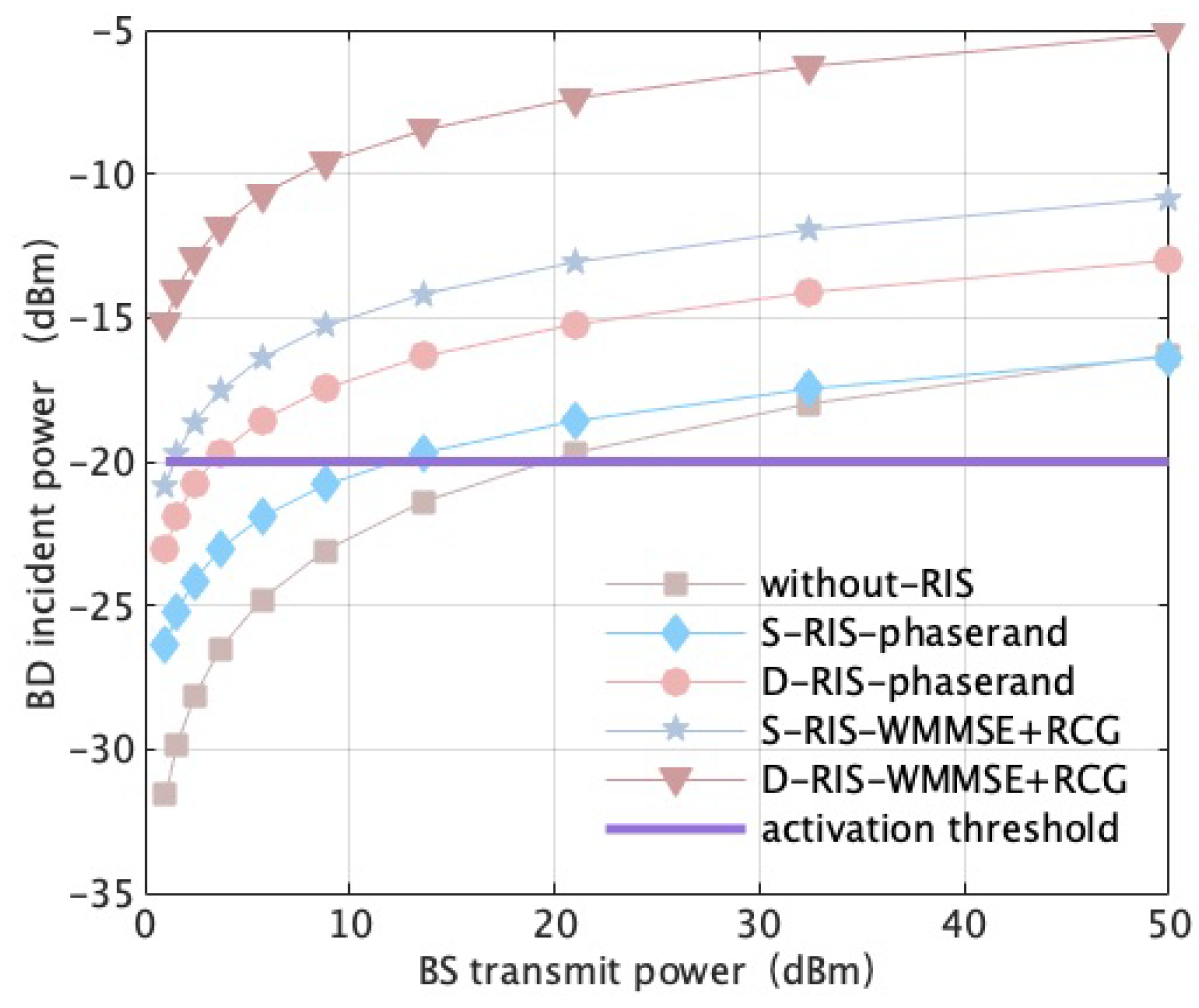
Figure 2 shows the incident power at the BDs for different schemes as a function of the BS transmit power. Compared with the case without RISs, the schemes assisted by RISs can significantly improve the incident power at BDs under the same BS transmit power. As can be seen, the proposed D-RIS-WMMSE + RCG scheme is superior to other schemes. It is evident that deploying RISs can significantly improve the BS-BD link, and distributed RISs can achieve better performance by providing more available links. For example, compared to the RIS-phaserand schemes, a merit of exceeding about 8 dBm is obtained by the RIS-WMMSE + RCG schemes at 20 dBm BS transmit power. The reason is that the proposed scheme can enhance the RIS-assisted link and incident power at the BDs by alternately optimizing BS beamforming vectors w k and RIS phase shift matrices Θ . Obviously, BDs cannot reflect the signal when the incident power at the BDs is insufficient for the activation threshold. The presence of RISs between BS and BDs significantly increases the incident power of the BDs, even for a lower BS transmit power, thereby enhancing their operational range. This is also expected to improve the EE of the system due to its ultra-low energy consumption.
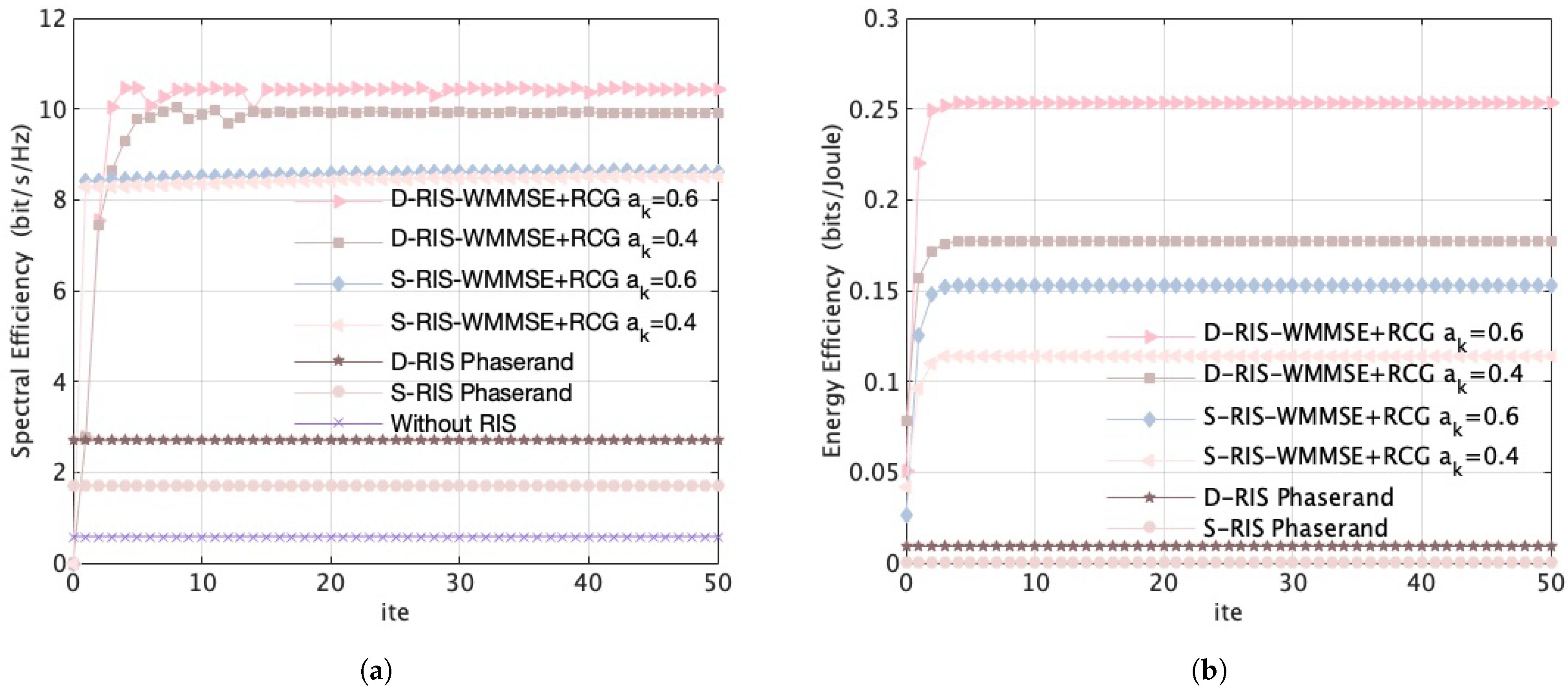
Figure 3 shows the SE and EE of the system for different schemes as a function of the number of iterations. As can be seen, all RIS-WMMSE + RCG schemes converged quickly and were significantly better than the RIS-phaserand schemes. This rapid convergence significantly reduced the effective time cost, making it highly suitable for dynamic environments. Figure 3a shows the SE of the BRs for different schemes when the trade-off factor λ = 0 (only SE is considered). The RIS-WMMSE + RCG schemes achieve approximately 8 bit/s/Hz improvement compared to the RIS-phaserand schemes. Figure 3b shows the EE of the backscatter V2I system for different schemes when the trade-off factor λ = 1 (only EE is considered). The RIS-WMMSE + RCG schemes achieve similarly superior performance compared to RIS-phaserand schemes. It is observed that without optimizing the phase shift matrices Θ , the performance improvement from deploying RISs becomes marginal. In the RIS-WMMSE + RCG schemes, we consider two power reflection coefficient options, and the performance at a k = 0.6 outperforms the case of the a k = 0.4 scheme in both Figure 3a,b. The reason is that within the possible range of a k , the higher values allocate more power for signal transmission, which promotes superior SE performance; the corresponding EE also increases with transmission power.
Figure 4 shows data collection volume for different schemes as a function of number of iterations. Unlike Figure 3, both EE and SE are taken into account simultaneously, assuming the trade-off factor λ = 0.5. It can be seen that all the proposed schemes demonstrate good convergence behavior, and the RIS-AO scheme which jointly optimizes the BS beamforming vectors w k , RIS phase shift matrices Θ , and BD power reflection coefficient a k begin to converge after 40 lotsof iterations. Although the convergence rate of the RIS-AO scheme is moderately lower than that of the RIS-WMMSE + RCG schemes, the performance is better. The reason is that incorporating dynamic a k optimization into the joint optimization of BS beamforming and RIS phase shifts increases algorithmic complexity and requires more steps to get converged. Compared to the RIS-WMMSE + RCG schemes where a k remains constant throughout the optimization process, the data collection volume of BRs will be significantly enhanced by the RIS-AO scheme due to dynamically optimizing a k during the optimization process.
Figure 5 shows the data collection volume for different schemes as a function of the power reflection coefficient of BD a k . Assume that all the proposed algorithms have come to stable convergence (ite = 40). It can be seen that the introduction of RISs significantly increases the data collection volume of the system, and the RIS-AO scheme outperforms the other D-RIS-WMMSE + RCG schemes. For the RIS-WMMSE + RCG scheme with a given trade-off factor, e.g., λ = 0.5, 0.6, and 0.7, when the constraint (42) is not satisfied, or when the BD fails to reach the activation threshold, the data collection volume will be reduced to 0 bit/Hz. For the proposed RIS-AO scheme, the BD power reflection coefficient a k can be alternately optimized with the BS beamforming vectors and RIS phase shifts to achieve its optimal value. Under identical trade-off factors, it obtains a higher BR data collection volume than the static schemes with given a k ; the superiority of the proposed RIS-AO scheme stems from its dynamic a k adaptation capability. Consequently, dynamic a k optimization plays a vital role in practical V2I application scenarios, enabling the RIS-AO scheme to achieve significant gains in the system’s SE.
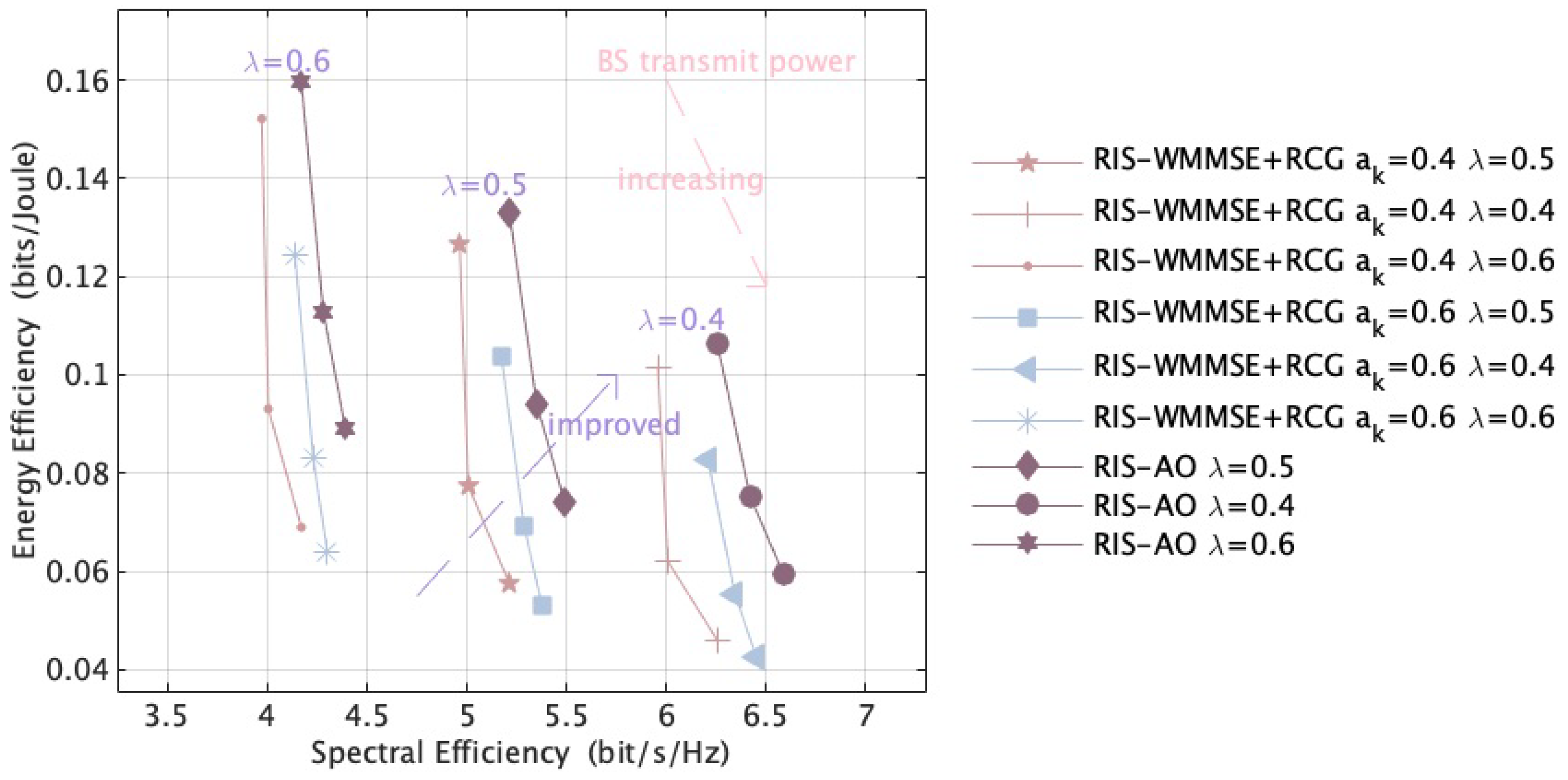
Figure 6 shows the EE for different schemes as a function of SE. It can be seen that, under an identical trade-off factor, the proposed RIS-AO scheme enhances the SE and EE performance of the system compared to the RIS-WMMSE + RCG schemes with given a k (i.e., a k = 0.4 or a k = 0.6). For example, with a trade-off factor = 0.5, the proposed RIS-AO scheme achieves approximately 0.5 bit/s/Hz higher SE than the RIS-WMMSE + RCG with a k = 0.4 when EE is 0.08 bits/Joule. The reason is that, for each specific trade-off factor λ selected in practical V2I application scenarios, the RIS-AO scheme dynamically optimizes the BS beamforming vectors and RIS phase shifts while adaptively tuning the BD power reflection coefficient a k based on the BD activation threshold and the SINR of BR requirements. Under the diverse trade-off factors, e.g., λ = 0.5, 0.6, and 0.7, the improvement in SE results in a decrease in EE for all RIS-enabled schemes. When λ is large, EE is prioritized by assigning it a larger weight in the objective function; EE improvement generally comes at the cost of decreased SE, and this trade-off operates reciprocally. Therefore, we can appropriately select the trade-off factors according to the requirements of the practical V2I scenario to boost the comprehensive EE and SE of the system via the RIS-AO scheme.

6. Conclusions

This paper investigates the trade-off between EE and SE by a multi-objective optimization framework based on the linear weighting method in a distributed RIS-assisted backscatter V2I communication system. We pioneer an AO scheme which jointly optimizes the BS beamforming vector, RIS phase shift matrix, and power reflection coefficient of BDs. The beamforming of the BS and RIS is designed by the WMMSE and the RCG algorithms, respectively, and then the power reflection coefficients of BDs are dynamically optimized according to the trade-off factor, which is constrained by their activation requirements and the vehicle’s minimum diverse QoS. Simulation results validate that the proposed algorithm exhibits excellent convergence performance, with stable and rapid convergence characteristics observed across multiple sets of experimental parameters. It is also demonstrated that the dynamic adjustment of the power reflection coefficient of BD plays an essential role in optimizing both the EE and SE of the system. Compared to the schemes that only optimize the beamforming of BS and RIS, the proposed scheme herein can determine the optimal BD power reflection coefficient based on the different trade-off factors, thereby significantly enhancing overall system performance. Moreover, since the trade-off factor can be dynamically adjusted in response to diverse application requirements in V2I scenarios, it exerts a simultaneous influence on the alternating optimization of the BS beamforming vector, RIS phase shift matrix, and BD power reflection coefficient, which in turn further impacts the system’s EE and SE performance.

Author Contributions

Conceptualization, methodology, software, validation, formal analysis, investigation, data curation, writing—original draft preparation, visualization, Y.D. and P.X.; resources, writing—review and editing, supervision, project administration, funding acquisition, P.X., X.L., Y.W. and Y.L. All authors have read and agreed to the published version of the manuscript.

Funding

This research was funded by General Project of the Education Department of Liaoning Province, grant number JYTMS20230285; Scientific Research Platform Construction Project of the Education Department of Liaoning Province, grant number LJ232510143007; Shenyang Science and Technology Project, grant number 23-503-6-18; Fundamental Research Funds for the Universities of Liaoning Province, grant number LJ232410143060; Natural Science Foundation of Liaoning Province of China, grant number 2024-MS-135 and LJKMZ20240008; National Natural Science Foundation of China, grant number 62301342.

Data Availability Statement

Data will be made available on request.

Conflicts of Interest

The authors declare no conflicts of interest.

References

  1. Song, J.; Lee, J.-H.; Noh, S. Position-Based Adaptive Beamforming and Roadside Unit Sectorization for V2I Communications. IEEE Trans. Veh. Technol. 2024, 73, 2960–2965. [Google Scholar] [CrossRef]
  2. Hong, M.; Choi, W.; Choi, S. Event Information Delivery Method Using Location Information for Route Replanning in V2I Local Environment. In Proceedings of the 2025 27th International Conference on Advanced Communications Technology (ICACT), Pyeong Chang, Republic of Korea, 16–19 February 2025; pp. 297–300. [Google Scholar]
  3. Qiao, Y.; Niu, Y.; Su, L.; Mao, S.; Wang, N.; Zhang, Z.; Ai, B. Deep Reinforcement Learning-Based mmWave Beam Alignment for V2I Communications. IEEE Trans. Mach. Learn. Commun. Netw. 2024, 2, 1216–1228. [Google Scholar] [CrossRef]
  4. Wang, Y.; Zhou, M.; Sun, Y.; Wang, K. Mobility-Aware Power Control and User Scheduling for Downlink V2I Networks. In Proceedings of the 2024 IEEE 100th Vehicular Technology Conference (VTC2024-Fall), Washington, DC, USA, 7–10 October 2024; pp. 1–5. [Google Scholar]
  5. Choi, P.; Kim, J.; Kwak, J. Joint Task Offloading and Resource Allocation for Integrated V2V and V2I Communication. In Proceedings of the 2024 15th International Conference on Information and Communication Technology Convergence (ICTC), Jeju Island, Republic of Korea, 16–18 October 2024; pp. 609–610. [Google Scholar]
  6. Zhao, R.; Mishra, D.; Seneviratne, A. Securing V2I Backscattering from Eavesdropper. In Proceedings of the ICC 2024—IEEE International Conference on Communications, Denver, CO, USA, 9–13 June 2024; pp. 2179–2184. [Google Scholar]
  7. Rastogi, A.; Yadav, S.; Gour, R.; Purohit, N.; Gurjar, D.S. Ergodic Capacity Analysis of AmBC-Assisted V2V Communications Over Cascaded Rayleigh Fading. In Proceedings of the 2024 IEEE 8th International Conference on Information and Communication Technology (CICT), Prayagraj, India, 6–8 December 2024; pp. 1–5. [Google Scholar]
  8. Asiedu, D.K.P.; Ofori-Amanfo, K.A.; Benjillali, M.; Yun, J.-H.; Saoudi, S. Sum-Rate Maximization of Symbiotic Multi-V2X MISO and Multi-RIS BackCom with Imperfections. In Proceedings of the 2024 IEEE 100th Vehicular Technology Conference (VTC2024-Fall), Washington, DC, USA, 7–10 October 2024; pp. 1–5. [Google Scholar]
  9. Khan, W.U.; Jameel, F.; Kumar, N.; Jäntti, R.; Guizani, M. Backscatter-Enabled Efficient V2X Communication with Non-Orthogonal Multiple Access. IEEE Trans. Veh. Technol. 2021, 70, 1724–1735. [Google Scholar] [CrossRef]
  10. Khan, W.U.; Jamshed, M.A.; Lagunas, E.; Chatzinotas, S.; Li, X.; Ottersten, B. Energy Efficiency Optimization for Backscatter Enhanced NOMA Cooperative V2X Communications Under Imperfect CSI. IEEE Trans. Intell. Transp. Syst. 2023, 24, 12961–12972. [Google Scholar] [CrossRef]
  11. Loku Galappaththige, D.A.; Rezaei, F.; Tellambura, C.; Herath, S. Link Budget Analysis for Backscatter-Based Passive IoT. IEEE Access 2022, 10, 128890–128922. [Google Scholar] [CrossRef]
  12. Rezaei, F.; Galappaththige, D.; Tellambura, C.; Herath, S. Coding Techniques for Backscatter Communications—A Contemporary Survey. IEEE Commun. Surv. Tutor. 2023, 25, 1020–1058. [Google Scholar] [CrossRef]
  13. Pinuela, M.; Mitcheson, P.D.; Lucyszyn, S. Ambient RF Energy Harvesting in Urban and Semi-Urban Environments. IEEE Trans. Microw. Theory Tech. 2013, 61, 2715–2726. [Google Scholar] [CrossRef]
  14. Song, C.; Huang, Y.; Zhou, J.; Zhang, J.; Yuan, S.; Carter, P. A High-Efficiency Broadband Rectenna for Ambient Wireless Energy Harvesting. IEEE Trans. Antennas Propag. 2015, 63, 3486–3495. [Google Scholar] [CrossRef]
  15. Palazzi, V.; Hester, J.; Bito, J.; Alimenti, F.; Kalialakis, C.; Collado, A.; Mezzanotte, P.; Georgiadis, A.; Roselli, L.; Tentzeris, M.M. A Novel Ultra-Lightweight Multiband Rectenna on Paper for RF Energy Harvesting in the Next Generation LTE Bands. IEEE Trans. Microw. Theory Tech. 2018, 66, 366–379. [Google Scholar] [CrossRef]
  16. Shen, S.; Zhang, Y.; Chiu, C.-Y.; Murch, R. A Triple-Band High-Gain Multibeam Ambient RF Energy Harvesting System Utilizing Hybrid Combining. IEEE Trans. Ind. Electron. 2020, 67, 9215–9226. [Google Scholar] [CrossRef]
  17. Ma, W.; Wang, W.; Jiang, T. Joint Energy Harvest and Information Transfer for Energy Beamforming in Backscatter Multiuser Networks. IEEE Trans. Commun. 2021, 69, 1317–1328. [Google Scholar] [CrossRef]
  18. Long, R.; Yang, G.; Pei, Y.; Zhang, R. Transmit Beamforming for Cooperative Ambient Backscatter Communication Systems. In Proceedings of the 2017 IEEE Global Communications Conference (GLOBECOM), Singapore, 4–8 December 2017; pp. 1–6. [Google Scholar]
  19. Gong, S.; Huang, X.; Xu, J.; Liu, W.; Wang, P.; Niyato, D. Backscatter Relay Communications Powered by Wireless Energy Beamforming. IEEE Trans. Commun. 2018, 66, 3187–3200. [Google Scholar] [CrossRef]
  20. Yang, G.; Ho, C.K.; Guan, Y.L. Multi-Antenna Wireless Energy Transfer for Backscatter Communication Systems. IEEE J. Sel. Areas Commun. 2015, 33, 2974–2987. [Google Scholar] [CrossRef]
  21. Clerckx, B.; Bayguzina, E. Waveform Design for Wireless Power Transfer. IEEE Trans. Signal Process. 2016, 64, 6313–6328. [Google Scholar] [CrossRef]
  22. Liang, Y.-C.; Zhang, Q.; Wang, J.; Long, R.; Zhou, H.; Yang, G. Backscatter Communication Assisted by Reconfigurable Intelligent Surfaces. Proc. IEEE 2022, 110, 1339–1357. [Google Scholar] [CrossRef]
  23. Samir, A.; Ibrahim, A.S.; Ismail, M.H.; ElHalawany, B.M.; Elsayed, M. Outage Performance of RIS-Assisted AmBC-NOMA Cooperative V2I Communications. IEEE Open J. Commun. Soc. 2024, 5, 4371–4382. [Google Scholar] [CrossRef]
  24. Wang, J.; Han, S.; Li, C.; Meng, W. Efficient Data Collection Scheme for IRS-Based V2I Backscatter Communications. IEEE Wirel. Commun. Lett. 2024, 13, 1128–1132. [Google Scholar] [CrossRef]
  25. Wang, J.; Han, S.; Li, J.; Li, C. IRS-Enabled Monostatic Backscatter MIMO Communication Design for V2I Networks. IEEE Trans. Veh. Technol. 2024, 73, 19287–19298. [Google Scholar] [CrossRef]
  26. Han, S.; Wang, J.; Li, J.; Li, C. IRS-Enabled Secure Backscatter Communication Design for V2I MIMO Networks. IEEE Wirel. Commun. Lett. 2024, 13, 2591–2595. [Google Scholar] [CrossRef]
  27. Galappaththige, D.; Rezaei, F.; Tellambura, C.; Herath, S. Optimizing Passive Tag Performance with Reconfigurable Intelligent Surfaces in Bistatic Backscatter Networks. IEEE Trans. Veh. Technol. 2024, 73, 12917–12933. [Google Scholar] [CrossRef]
  28. Galappaththige, D.L.; Rezaei, F.; Tellambura, C.; Herath, S. RIS-Empowered Ambient Backscatter Communication Systems. IEEE Wirel. Commun. Lett. 2023, 12, 173–177. [Google Scholar] [CrossRef]
  29. Liu, Q.; Fu, M.; Li, W.; Xie, J.; Kadoch, M. RIS-Assisted Ambient Backscatter Communication for SAGIN IoT. IEEE Internet Things J. 2023, 10, 9375–9384. [Google Scholar] [CrossRef]
  30. Zhang, M.; Tan, L.; Huang, K.; You, L. On the Trade-Off between Energy Efficiency and Spectral Efficiency in RIS-Aided Multi-User MISO Downlink. Electronics 2021, 10, 1307. [Google Scholar] [CrossRef]
  31. Wan, J.; Guan, Y.; Song, J.; Song, Q.; Guo, L. Energy Efficiency and Spectral Efficiency Tradeoff in Multi-BD Symbiotic Radio Systems. In Proceedings of the 2023 IEEE/CIC International Conference on Communications in China (ICCC), Dalian, China, 10–12 August 2023; pp. 1–6. [Google Scholar]
  32. You, L.; Xiong, J.; Ng, D.W.K.; Yuen, C.; Wang, W.; Gao, X. Energy Efficiency and Spectral Efficiency Tradeoff in RIS-Aided Multiuser MIMO Uplink Transmission. IEEE Trans. Signal Process. 2021, 69, 1407–1421. [Google Scholar] [CrossRef]
  33. Faisal, A.; Al-Nahhal, I.; Dobre, O.A.; Ngatched, T.M.N. Deep Reinforcement Learning for RIS-Assisted FD Systems: Single or Distributed RIS? IEEE Commun. Lett. 2022, 26, 1563–1567. [Google Scholar] [CrossRef]
  34. Bian, J.; Wang, C.-X.; Gao, X.; You, X.; Zhang, M. A General 3D Non-Stationary Wireless Channel Model for 5G and Beyond. IEEE Trans. Wirel. Commun. 2021, 20, 3211–3224. [Google Scholar] [CrossRef]
  35. Yang, H.; Ye, Y.; Chu, X. Max-Min Energy-Efficient Resource Allocation for Wireless Powered Backscatter Networks. IEEE Wirel. Commun. Lett. 2020, 9, 688–692. [Google Scholar] [CrossRef]
  36. Shi, Q.; Razaviyayn, M.; Luo, Z.-Q.; He, C. An Iteratively Weighted MMSE Approach to Distributed Sum-Utility Maximization for a MIMO Interfering Broadcast Channel. In Proceedings of the 2011 IEEE International Conference on Acoustics, Speech and Signal Processing (ICASSP), Prague, Czech Republic, 22–27 May 2011; pp. 3060–3063. [Google Scholar]
  37. Guo, H.; Liang, Y.-C.; Chen, J.; Larsson, E.G. Weighted Sum-Rate Maximization for Reconfigurable Intelligent Surface Aided Wireless Networks. IEEE Trans. Wirel. Commun. 2020, 19, 3064–3076. [Google Scholar] [CrossRef]
  38. Yu, X.; Xu, D.; Schober, R. MISO Wireless Communication Systems via Intelligent Reflecting Surfaces: (Invited Paper). In Proceedings of the 2019 IEEE/CIC International Conference on Communications in China (ICCC), Changchun, China, 11–13 August 2019; pp. 735–740. [Google Scholar]
Figure 1. RIS-assisted BackCom system in V2I scenario.
Electronics 14 03800 g001
Figure 2. BD incident power versus BS transmit power.
Electronics 14 03800 g002
Figure 3. Convergence behavior: (a) Spectral efficiency versus the number of iterations. (b) Energy efficiency versus the number of iterations.
Electronics 14 03800 g003
Figure 4. Data collection volume versus the number of iterations.
Electronics 14 03800 g004
Figure 5. Data collection volume versus power reflection coefficient of BD.
Electronics 14 03800 g005
Figure 6. Energy efficiency versus spectral efficiency.
Electronics 14 03800 g006
Table 1. Parameters Value.
ParametersValue
Number of BS antennas ( M )128
Number of RIS reflection elements ( N )100
Number of BDs with single antennas ( K )4
Carrier frequency28 GHz
Transmission bandwidth100 MHz
BD-BR sub-channel path loss22.55 + 35.3lg d + 20g f dB
Backscattering period ( T B )4 s
Noise power spectral density−174 dBm/Hz
Sampling frequency1 × 104 Hz
BR moving speed2 m/s
Width and height of the RIS elements0.234 times the wavelength
RIS pose[[0, 0, −1]; [−0.7071, 0.7071, 0]; [0.7071, 0.7071, 0]]
Passive BD activation threshold ( P b )−20 dBm
Disclaimer/Publisher’s Note: The statements, opinions and data contained in all publications are solely those of the individual author(s) and contributor(s) and not of MDPI and/or the editor(s). MDPI and/or the editor(s) disclaim responsibility for any injury to people or property resulting from any ideas, methods, instructions or products referred to in the content.