Figure 1.
Relationship to prior studies and contributions of this paper ([Ko:2025e] = [
29] and [Ko:2025s] = [
30]).
Figure 1.
Relationship to prior studies and contributions of this paper ([Ko:2025e] = [
29] and [Ko:2025s] = [
30]).
Figure 2.
Dual-hop AF relay systems with SWIPT architecture: (a) SWIPT relaying system having R relay nodes, (b) rth SWIPT relay node.
Figure 2.
Dual-hop AF relay systems with SWIPT architecture: (a) SWIPT relaying system having R relay nodes, (b) rth SWIPT relay node.
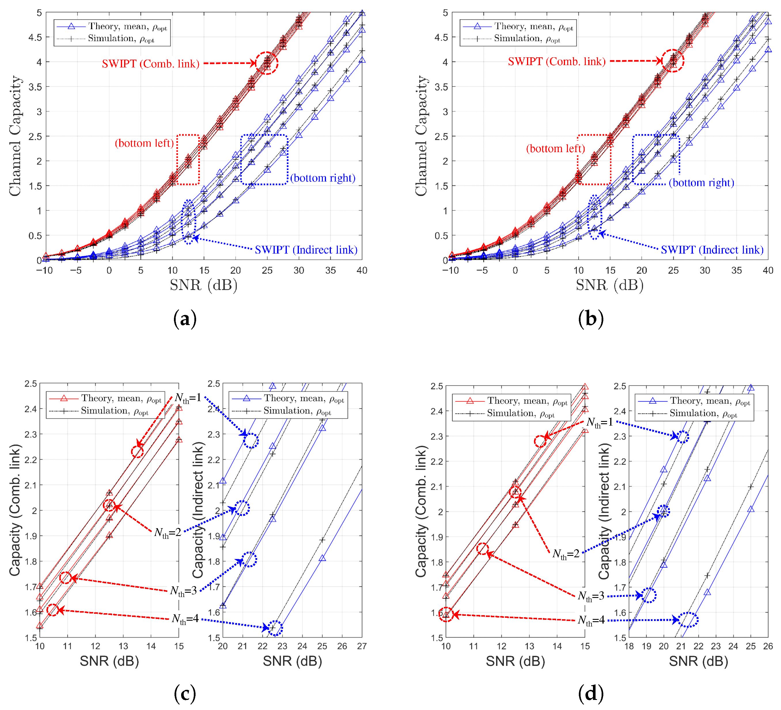
Figure 3.
Channel capacity comparison versus SNR with power splitting optimization under SR link-based relay selection ( or , , Ch. Model): (a) , (b) , (c) vs. .
Figure 3.
Channel capacity comparison versus SNR with power splitting optimization under SR link-based relay selection ( or , , Ch. Model): (a) , (b) , (c) vs. .
Figure 4.
Channel capacity comparison versus SNR with power splitting optimization under SR link-based relay selection ( or , , Ch. Model): (a) , (b) , (c) vs. .
Figure 4.
Channel capacity comparison versus SNR with power splitting optimization under SR link-based relay selection ( or , , Ch. Model): (a) , (b) , (c) vs. .
Figure 5.
Channel capacity comparison versus SNR with power-splitting optimization under SR link-based relay selection ( or , , Ch. Model): (a) , (b) , (c) vs. .
Figure 5.
Channel capacity comparison versus SNR with power-splitting optimization under SR link-based relay selection ( or , , Ch. Model): (a) , (b) , (c) vs. .
Figure 6.
Channel capacity comparison versus SNR with power splitting optimization under SR link-based relay selection ( or , , Ch. Model): (a) , (b) , (c) vs. .
Figure 6.
Channel capacity comparison versus SNR with power splitting optimization under SR link-based relay selection ( or , , Ch. Model): (a) , (b) , (c) vs. .
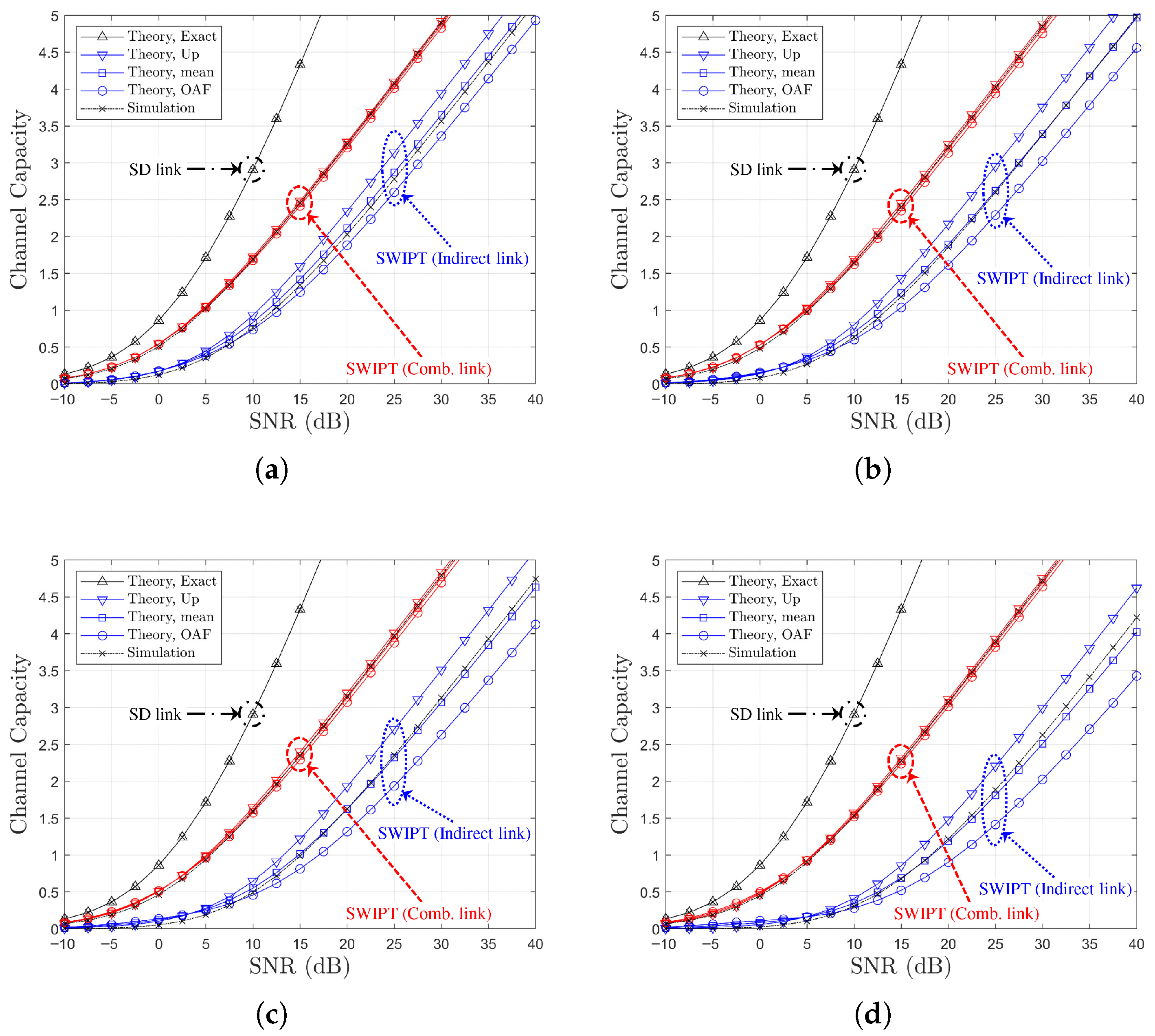
Figure 7.
Channel capacity comparison versus SNR for SR link-based relay selection of the best relay (, , Ch. Model): (a) , (b) , (c) , and (d) .
Figure 7.
Channel capacity comparison versus SNR for SR link-based relay selection of the best relay (, , Ch. Model): (a) , (b) , (c) , and (d) .
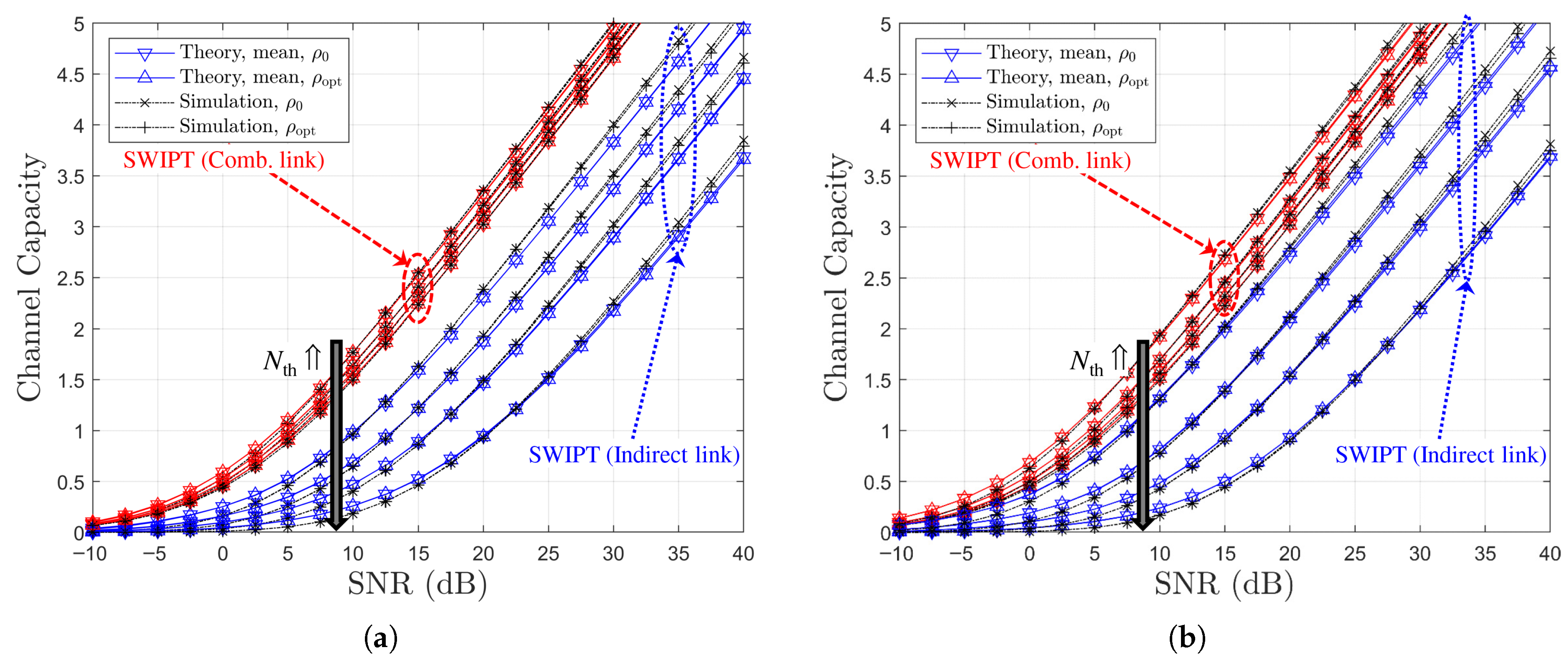
Figure 8.
Channel capacity comparison versus SNR for SR link-based relay selection of the best relay ( or , ): (a) Ch. Model, (b) Ch. Model.
Figure 8.
Channel capacity comparison versus SNR for SR link-based relay selection of the best relay ( or , ): (a) Ch. Model, (b) Ch. Model.
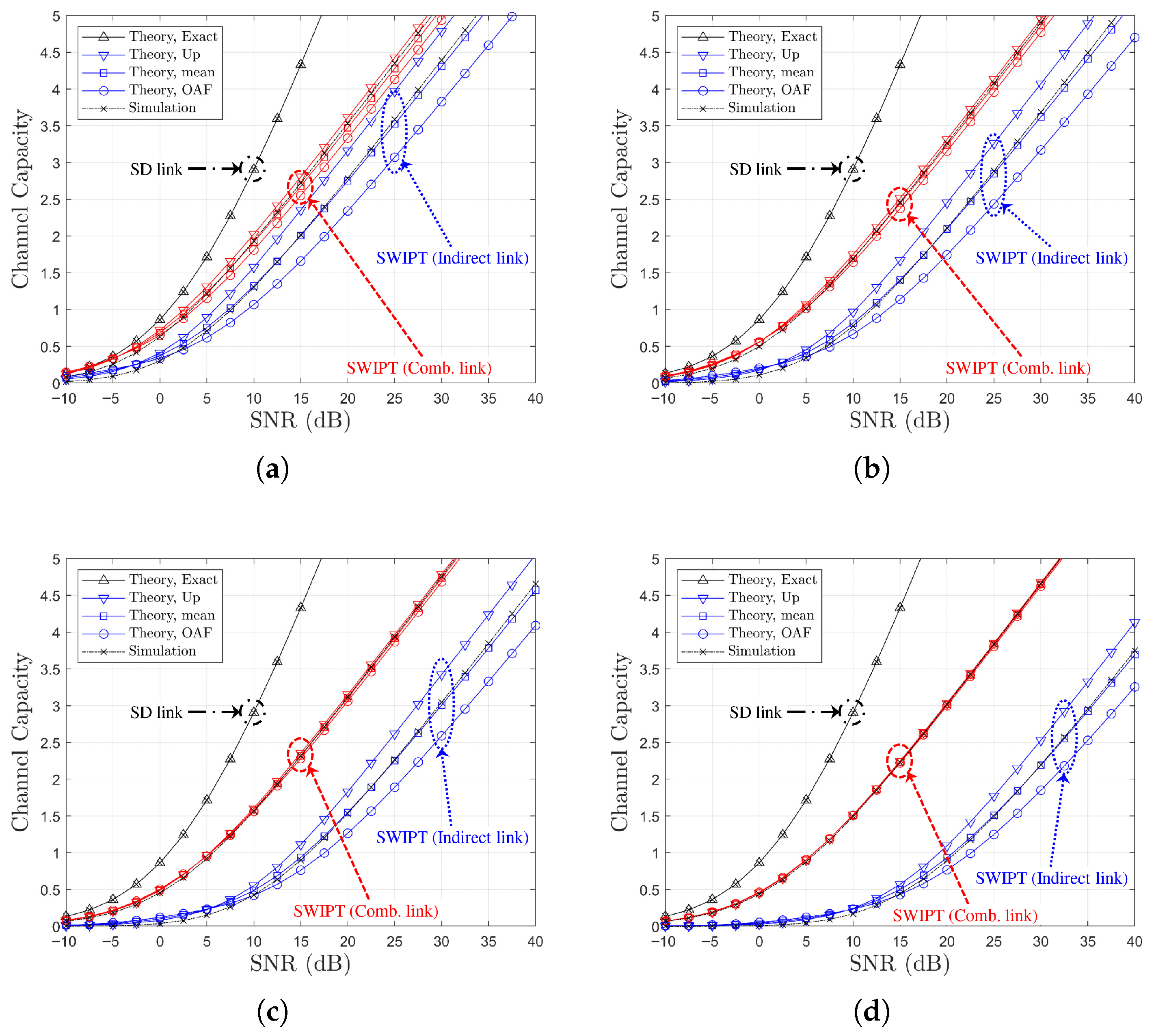
Figure 9.
Channel capacity comparison versus SNR for RD link-based relay selection of the best relay (, , Ch. Model): (a) , (b) , (c) , and (d) .
Figure 9.
Channel capacity comparison versus SNR for RD link-based relay selection of the best relay (, , Ch. Model): (a) , (b) , (c) , and (d) .
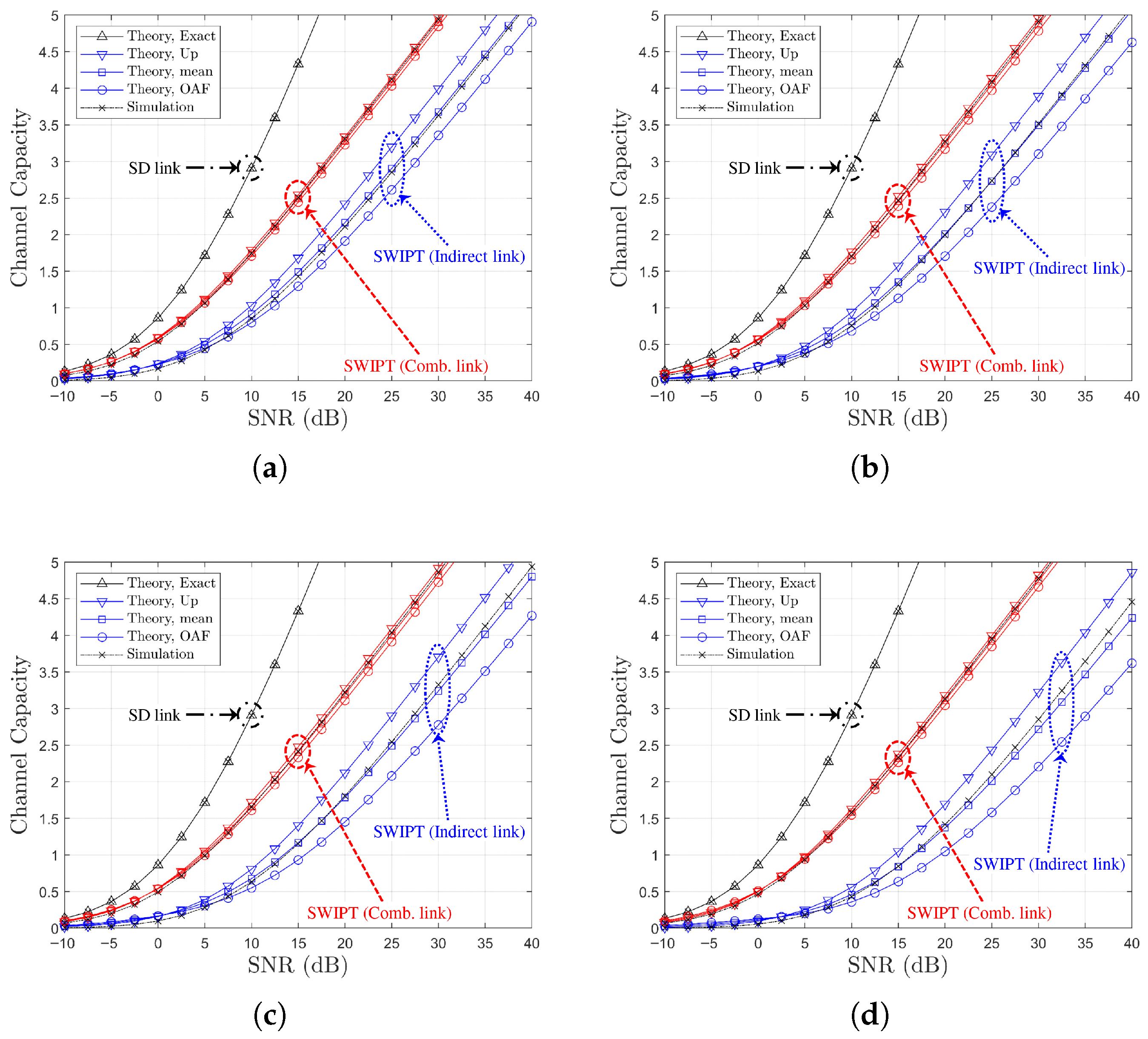
Figure 10.
Channel capacity comparison versus SNR for RD link-based relay selection of the best relay (, , Ch. Model): (a) , (b) , (c) , and (d) .
Figure 10.
Channel capacity comparison versus SNR for RD link-based relay selection of the best relay (, , Ch. Model): (a) , (b) , (c) , and (d) .
Figure 11.
Channel capacity comparison versus SNR for RD link-based relay selection of the best relay (, ): (a) Ch. Model (both links), (b) Ch. Model (both links), (c) Ch. Model (separate link), and (d) Ch. Model (separate link).
Figure 11.
Channel capacity comparison versus SNR for RD link-based relay selection of the best relay (, ): (a) Ch. Model (both links), (b) Ch. Model (both links), (c) Ch. Model (separate link), and (d) Ch. Model (separate link).
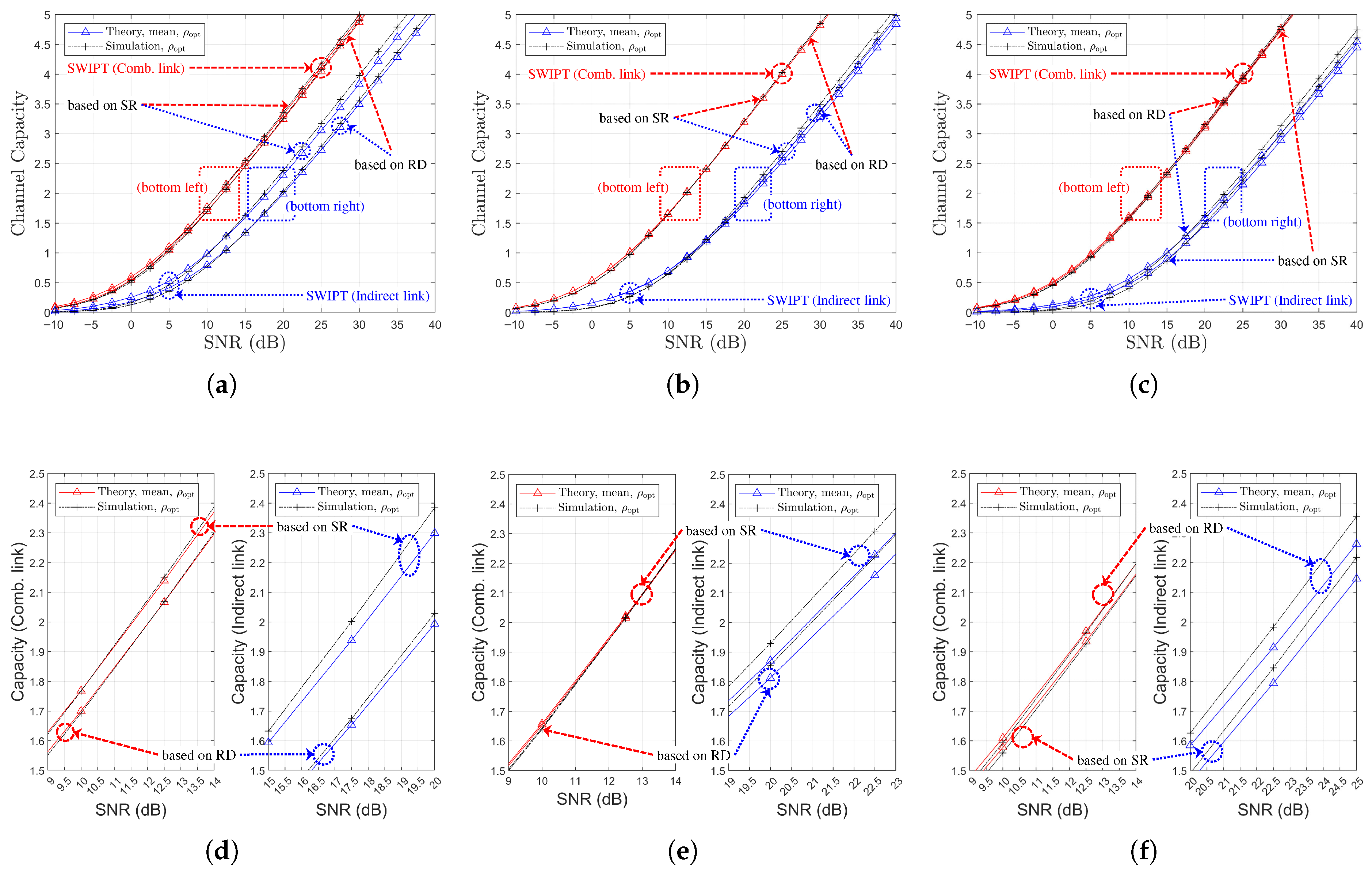
Figure 12.
Comparison of channel capacity as a function of SNR, , and relay selection strategies (, , Ch. Model): (a) (both links), (b) (both links), (c) (both links), (d) (separate link), (e) (separate link), and (f) (separate link).
Figure 12.
Comparison of channel capacity as a function of SNR, , and relay selection strategies (, , Ch. Model): (a) (both links), (b) (both links), (c) (both links), (d) (separate link), (e) (separate link), and (f) (separate link).
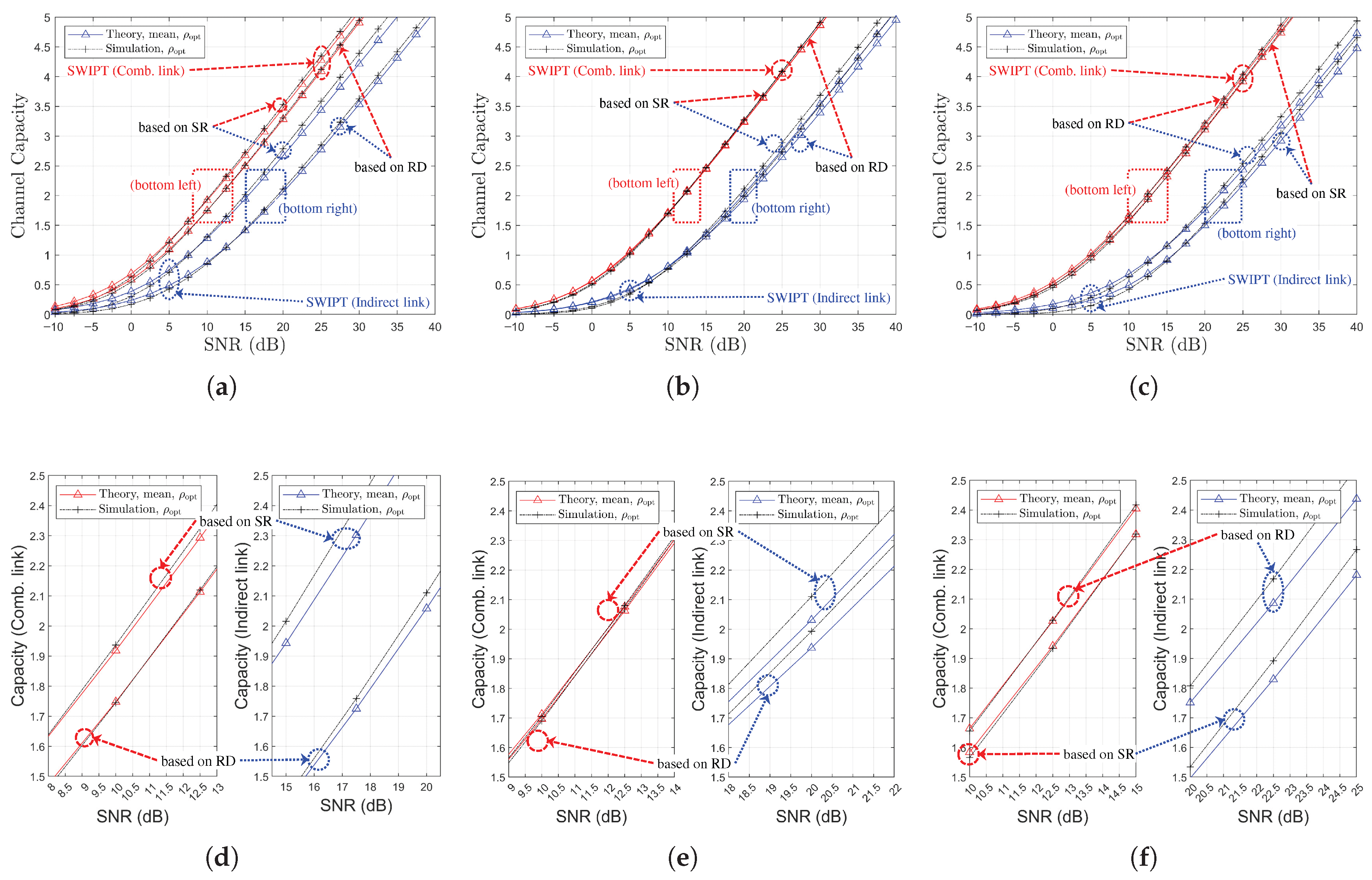
Figure 13.
Comparison of channel capacity as a function of SNR, , and relay selection strategies (, , Ch. Model): (a) (both links), (b) (both links), (c) (both links), (d) (separate link), (e) (separate link), and (f) (separate link).
Figure 13.
Comparison of channel capacity as a function of SNR, , and relay selection strategies (, , Ch. Model): (a) (both links), (b) (both links), (c) (both links), (d) (separate link), (e) (separate link), and (f) (separate link).
Table 1.
Considered channel models for the SWIPT OAF relaying system.
Table 1.
Considered channel models for the SWIPT OAF relaying system.
| Ch. Models | Average Fading Powers | R |
|---|
| SD | SR | RD |
|---|
| | | | 4 |
| | | | 4 |
Table 2.
Descriptions of legend entries for SWIPT OAF relaying systems using P-CSI of SR links.
Table 2.
Descriptions of legend entries for SWIPT OAF relaying systems using P-CSI of SR links.
| Legend | Symbol | Equation(s) | Remarks |
|---|
| Theory,OAF | , | (27) and (28) | OAF Approximation (Semi-Lower Bound) |
| Theory,Up | , | (29) and (32) | Upper Bound |
| Theory,mean | | (33) | Mean Capacity |
| (34) |
Table 3.
Descriptions of legend entries for SWIPT OAF relaying systems using P-CSI of RD links.
Table 3.
Descriptions of legend entries for SWIPT OAF relaying systems using P-CSI of RD links.
| Legend | Symbol | Equation(s) | Remarks |
|---|
| Theory,OAF | , | (44) and (45) | OAF Approximation (Semi-Lower Bound) |
| Theory,Up | , | (46) and (49) | Upper Bound |
| Theory,mean | | (50) | Mean Capacity |
| | (51) |
Table 4.
SNR improvement (dB) for each relay selection criterion.
Table 4.
SNR improvement (dB) for each relay selection criterion.
| Ch. Model | | Gain for Comb. Link 1 | Gain for Indirect Link 2 | From |
|---|
| 1 | >0.5 | >2.25 | Figure 12a,d |
| 2 | ≈0.0 | >0.5 | Figure 12b,e |
| 3 | <−0.25 | <−1.0 | Figure 12c,f |
| 1 | >1.25 | >4.2 | Figure 13a,d |
| 2 | ≈0.0 | >0.75 | Figure 13b,e |
| 3 | <−0.75 | <−3.25 | Figure 13c,f |


