Review

Flux-Weakening Control Methods for Permanent Magnet Synchronous Machines in Electric Vehicles at High Speed

1
Department of Electrical and Computer Engineering, Texas Tech University, Lubbock, TX 79409, USA
2
Intelligent Robotic and Energy Systems Research Group, Faculty of Engineering and Design, Carleton University, Ottawa, ON K1S 5B6, Canada
3
Department of Electrical and Computer Engineering, Old Dominion University, Norfolk, VA 23529, USA
*
Authors to whom correspondence should be addressed.
Electronics 2025, 14(19), 3779; https://doi.org/10.3390/electronics14193779
Submission received: 7 September 2025 / Revised: 21 September 2025 / Accepted: 21 September 2025 / Published: 24 September 2025
(This article belongs to the Special Issue Advanced Control and Power Electronics for Electric Vehicles)

Abstract

Permanent magnet synchronous motors (PMSMs) are widely favored by manufacturers for use in electric vehicles (EVs) because of their many benefits, which include high power density at high speeds, ruggedness, potential for high efficiency, and reduced control complexity. However, since the Back Electromotive Force (EMF) increases proportionally with the motor’s rotational speed, it must be carefully controlled at high speeds. Flux-weakening (FW) control is required to avoid excessive electromagnetic flux beyond the power source and inverter’s voltage restrictions. This paper aims to compare various FW control strategies and analyze their effectiveness in maximizing the speed of PMSMs in EV applications while ensuring stable and reliable performance. Various FW approaches, such as voltage-based control, current-based control, and advanced predictive control methods, are examined to determine how each method balances speed enhancement with torque output and efficiency. In addition, other control strategies are crucial for optimizing the performance of PMSMs in electric vehicles. Among the most popular methods for controlling torque and speed in PMSMs are Field-Oriented Control (FOC), Direct Torque Control (DTC), and Vector Current Control (VCC). Each control technique has advantages and is frequently cited in the literature as a crucial instrument for improving EV motor control. This article provides a comprehensive evaluation of FW methods, highlighting their respective advantages and disadvantages by synthesizing the findings of numerous studies. In addition to outlining future research directions in FW control for EV applications, this study provides essential insights and valuable suggestions to help select FW control techniques for various PMSM types and operating conditions.

1. Introduction

The adoption of hybrid and fully electric vehicles (EVs) has become essential in reducing greenhouse gas emissions, thereby decreasing air pollution and promoting fuel savings. Permanent magnet synchronous motors (PMSMs) have mainly entered the transportation industry and are the most commonly used electric machines in EVs. Electric powertrains offer an excellent conversion of the electrical energy stored in capacitors, fuel cells, or batteries into traction force for the vehicle’s wheels. This electrical traction force is converted into motion through electromagnetic fields by an electric machine and inversely transformed from the wheel braking process into electrical energy again.
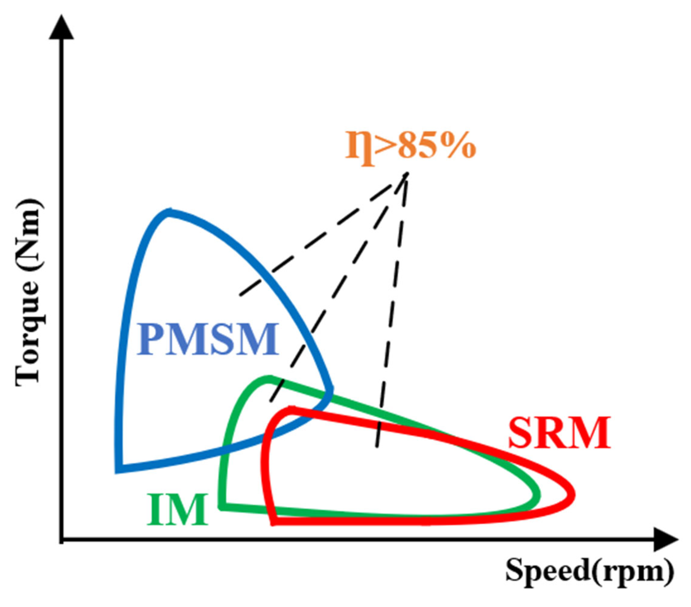
Compared to induction and brushless DC machines, PMSMs offer numerous distinct benefits. They provide strong torque and dynamic control, are compact, require minimal maintenance, and exhibit low torque ripple. Additionally, they are excited by permanent magnets, which results in speed restrictions and allows the excitation flux to be weakened. In order to distinguish between power and constant torque regions based on road topography, forward or reverse transition, and area, torque-speed characteristics are essential for electric machines used in EV applications across all speed ranges, which helps determine the appropriate speed range to be selected and whether high or low torque is needed [1]. Torque-speed characteristics in various speed ranges are seen in Figure 1 [2].
When selecting an electric machine for a vehicle, several factors must be considered, including the vehicle’s design, weight, size, space, required peak power, noise, vibration, harshness (NVH), torque-speed characteristics, and thermal constraints [3,4,5,6]. There are numerous popular ways to increase the traction of electric vehicles (EVs), including wound rotor synchronous machines (WRSMs), induction machines (IMs), permanent magnet synchronous machines: interior (IPMSM) and surface (SPMSM), and synchronous reluctance machines (SyRMs). However, IMs and PMSMs are the most commonly used for EVs [3,4,5,6,7,8,9,10,11,12,13,14,15,16]. SyRMs have recently gained popularity in the EV market because of their inexpensive cost, safe failure at high speed, and independence from rare earth magnetization [17]. Alternative technologies without the dependence on rare earth magnets have gained popularity in the EV industry due to the fluctuating pricing and scarcity of certain elements, such as dysprosium, neodymium, and terbium [18,19,20,21,22,23,24].
Scholars in the automotive industry have also taken an interest in ferrite Permanent Magnet-Assisted Synchronous Reluctance Machines (PM-assisted SynRM), Switch Reluctance Machines (SRM), and Squirrel Cage Induction Machines (IMs), which have made notable strides in the EV market [25,26,27,28,29,30,31,32,33,34,35,36,37,38,39]. Because the rotor’s manufacturing is symmetrical between the d and q axes set to the maximum, ferrite-PM-assisted SynRM may achieve a power density of roughly 75% of the IPMSM with the same size and liquid cooling technology. This also maximizes the relevant torque. However, the drawback is that the ferrite-PM-assisted SynRM electric machine demagnetizes at low temperatures. Therefore, it is necessary to preheat or reduce predetermining values before the machine starts [31,40,41]. Nevertheless, because of its powerhouse density, high efficiency, and resilience, manufacturers continue to favor the PMSM alternative. For high-speed applications where flux-weakening capability is significant, IPMSMs are employed, whereas SPMSMs are typically used for high-power-density needs [42]. Another emerging machine concept is the flux-modulation type, which uses asynchronous field harmonics to achieve energy conversion without the same pole number for the stator and the rotor as in conventional designs. Brushless Stator-Mounted Machines (BSMMs) are suitable and reliable for EV motors because of their high torque and high-speed performance, flux-weakening capability, and improved heat dissipation [43]. The performance and characteristics of various relevant machines (IM, PMSM, and SynRM) are compared in the literature [4,6,7,8,9,10]. Table 1 lists the overall attributes and quantitative traits of a few machine technologies utilized in EV applications [2,4,7,8,9,10,11,12,13,14,15].
Before selecting the most effective technology for a given application, several factors need to be evaluated. Manufacturers must assess the power, speed, torque, and other requirements specific to the EV application. Based on the reviewed literature [4,7,8,9,10,11,12,13,14,15], key features must be compared to determine the best technology for the application. In summary, these features should include the following:
(a)
Appropriate machine weight and space.
(b)
The entire cost of production and materials.
(c)
Defined standards for dependability.
(d)
The overload capability of the drive.
(e)
The characteristic of speed versus torque.
(f)
The overall efficiency of the operation.
It has become evident to EV producers that the PMSM is the optimal choice due to its high efficiency, greater power density, and robustness. Since more current is required at the field-weakening process for high speeds, PMSM is often a solid option for civic driving in terms of efficiency. Different zones for qualitative efficiency in constant power and constant torque of various machines are depicted in Figure 2 [2]. The parameters were given numerical numbers by the authors in [4], who also divided them into low, medium, and high ranges.
In addition to other components of power generation in electric machines, the control strategy plays a crucial role in ensuring efficiency in regions with steady power and torque. Power electronics and other sources must be used to increase overall efficiency. When considering the power and switching losses of the semiconductor, the current trajectory could be modified to be conventional at low speeds [44]. Variable modulation and variable switching frequency techniques are also used to increase low-speed ranges. While Continuous and Discontinuous PWM, which was created in the previous literature, produced some issues with tightness and noise vibration of the electric machine, the Space Vector PWM (SVPWM) technique is primarily utilized to reduce losses. Additionally, other techniques like virtual phase correction (VPC) and overmodulation with noise reduction (ONR) could be employed to reduce the losses in different speed ranges [45,46]. Future electric machine generations ought to aim for a variety of goals [47]:
  • High efficiency through magnet steels and appropriate copper alloys reduces copper and iron losses.
  • Cost reduction through contemporary configurations that maintain the same flux density and straightforward cooling system while relying on inexpensive non-rare-earth magnet material.
  • Motor design needs to be improved to facilitate recycling and separation.
  • High power density thanks to a high-performance cooling system that increases power capabilities and speed range.
Embedded software in electric vehicles manages real-time power flow between the source and the load to maximize energy, optimize motor control efficiency to make it more economical and drivable, make motor start/stop more functional, and enhance battery performance and protection for a longer lifespan. By determining the ideal operating point for maximum electric drive efficiency at both low and high speeds using a compatible circuit of electronics control with sub-smart systems for heating, battery management, and braking in EVs, an appropriate algorithm for managing the electric machine is selected. These days, the traction inverter is primarily responsible for managing the torque of the electric machine, which is dictated by the driver’s accelerator input and the position of the braking pedal, whether it operates as a motor (positive) or a generator (negative). Nevertheless, this traction inverter should respond to the other components for simpler high-level powertrain control functions using novel algorithms that can be summarized as follows [44,48,49]:
  • Control speed and torque using the right power electronics design to maximize the electric machine’s efficiency.
  • The machine’s inductance value, the flux distribution, saturation of the magnetic materials, and reluctance of the machine are nonlinearly altered, which leads to achieving the high saturation level required for both PMSMs and SyRMs to achieve optimal performance at high-speed ranges.
  • The drivetrain experiences losses due to the current total harmonic distortion control produced by the inverter or torque ripple.
  • Automatic algorithms that take into account the flux-weakening (FW) regulation and automatically adjust the parameters of the low-level controllers for electric machines.
Although electric machine technologies and control systems have advanced significantly, it is still difficult to manage PMSMs at high speeds while maintaining optimal performance. Numerous FW control strategies have been put forth in the literature, but there has not been a cohesive and current comparative analysis catered to EV traction needs. This research fills this vacuum by offering a thorough analysis of FW control techniques for PMSMs, looking at their advantages, disadvantages, and working principles.
In summary, the main contributions of this work include the following:
  • A thorough overview of flux-weakening control strategies (voltage-based, current-based, feedforward, feedback, and hybrid methods), including their theoretical foundations and practical implementation considerations.
  • New comparative evaluations of these FW methods, with summary tables providing qualitative and quantitative comparisons of performance, efficiency, and stability across different approaches.
  • A comparative analysis of FW control in different machine types—specifically contrasting SPMSM, IPMSM, and SynRM—to highlight how machine characteristics influence flux-weakening capability and control strategy selection.
  • Critical analysis and practical guidance for selecting appropriate FW control methods in EV applications, as well as the identification of current challenges and future research directions in this field.
This manuscript begins with a discussion of common control strategies of PMSMs in Section 2; in Section 3, a detailed description of the Maximum Torque per Ampere (MTPA) operating region in PMSMs is presented. Section 4 provides an overview and working elements of the FW strategy. In Section 5, a classification and analysis of various FW control methods are presented. In Section 6, there is a discussion on the main advantages and disadvantages of the reviewed FW strategies and their suitability for different machine types, summarizing key insights in a comparative table. Finally, Section 7 draws the major conclusions and outlines future research directions.

2. Different Techniques for Controlling PMSM

The PMSM is a crucial contemporary alternative to the IM due to its better torque density and efficiency. In contrast to induction machines, PMSMs may run at a steady frequency on AC mains. Specific approaches between the position of the rotor magnets and the AC excitation frequency source are required for PMSMs to be synchronized. Because of this, the PMSM is more beneficial for variable speed drives (VSDs) even though the high cost of power electronics is offset by the many long-standing benefits of the PMSM, like its excellent efficiency and quick dynamic response. Furthermore, permanent magnetic motors are being used in more demanding applications due to the availability of low-cost, improved applicable solutions for power electronics [50].
Numerous control schemes have been created to attain excellent performance for PMSM drives over the entire speed range. These include traditional techniques such as Direct Torque Control (DTC) and Field-Oriented Control (FOC), as well as techniques that focus on flux regulation, particularly Direct Voltage Control (DVC) and Direct Flux Vector Control (DFVC). In terms of complexity, dynamic response, efficiency, and torque ripple, each control strategy has specific benefits and disadvantages. In practice, modern EV drive controllers often integrate multiple approaches or select a specific control method based on particular performance application requirements and constraints.
It is worth noting that PMSM control can be implemented with or without mechanical rotor position sensors. However, with the increase in the cost of the drive system, this incremental encoder position sensor, which is mounted on the rotor shaft, provides precision position information at all speed ranges [51].
Sensorless control methods, such as high-frequency signal injection or back-EMF observers, rely on electrical measurement data, including terminal voltages and currents, to estimate the rotor position [52,53,54]. To increase reliability and lower costs in EV applications, sensorless control is highly desirable. In fact, many of the control strategies covered below have been modified for sensorless operation in the literature, even in the deep FW area. We provide a summary of the main PMSM control techniques for EVs in the following subsections.

2.1. Field-Oriented Control

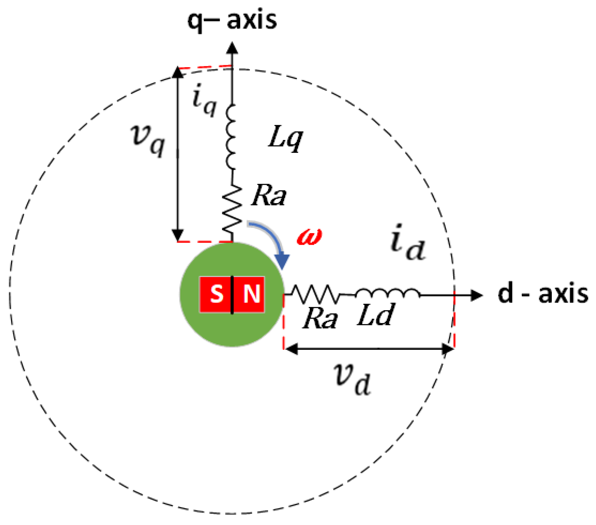
Vector Control (VC), also called Field-Oriented Control (FOC), is a popular high-performance control method that the PMSM uses in the closed-loop speed control mode. This technology controls PMSM and AC induction machines, giving them amazing capability control at full speed and torque limits. The basic idea of Vector Control (VC) is to divide the stator current vector into two parts: the torque current, which generates the mechanical force, and the magnetized current, which generates the magnetic field. The best motor control performance can be obtained by regulating the phase and amplitude of these two currents. In order to execute Vector Control, the stator current must be transformed from the steady reference frame to the rotor flux reference, or d-q reference frame. Figure 3 displays the d-q mathematical model of PMSM, as in [2]. R a denotes the equivalent resistance of the single winding in this figure; the equivalent voltages in the d-axis and the q-axis are represented by v d v q ; the equivalent currents in the d-axis and the q-axis are represented by i d and i q ; and the equivalent inductances in the d-axis and q-axis are represented by L d and L q . The voltages in this coordinate system are given by the following formula [2]:
  v d v q = R a + P L d ω L q ω L d R a + P L q i d i q + 0 ω λ
Here P is the differential operator, ω is the angular velocity of the rotor, P = d/dt; λ is the magnitude of the flux permanent magnet in stator.
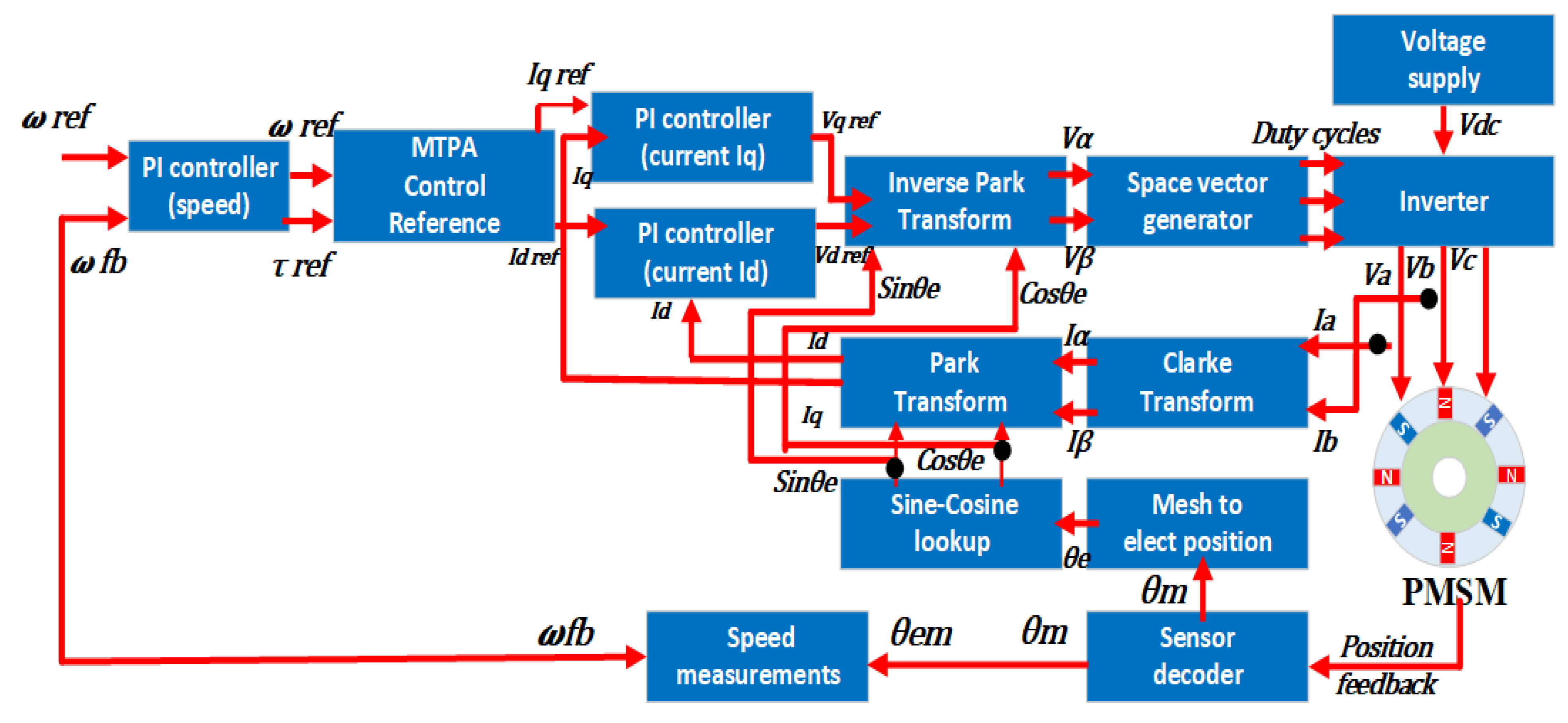
The fundamental elements of this PMSM control technique are maximum torque, maximum efficiency, i d = 0 , and weakening control. Maintaining the d-axis current at zero ( i d = 0 ) is the most often used technique for controlling the PMSM, which consists of three feedback loops connected in series (current loop, speed loop, and position loop). The inner loop (current loop) of the PMSM directly controls the genuine two components of torque and excitation, which may be measured using the two current sensors following the PARK and CLARKE transformation.
The two PI controllers adjust the torque and excitation components. Their outputs are then fed into an inverse PARK transform module to create the Space Vector Pulse Width Modulation (SVPWM) module, which feeds a three-phase inverter bridge. The techniques employed in this overall control system include coupling and decoupling [55,56,57]. The block diagram for the vector control system is shown in Figure 4 [2].
The CLARKE transformation converts the three-phase ABC coordinates into the stationary αβ coordinate system, hence transforming the motor’s three-phase windings into a two-phase quadrature winding. The CLARKE formula is presented in Ref. [2]:
  i α = i a
i β = 1 3 ( 2 i b + i a )
In the PARK transformation, the rotating d-q coordinate system is used to illustrate the process by converting the αβ coordinate system. On the other hand, the most crucial parameter in this transformation technique is the angle (θ) between the α-axis and the d-axis. The formula for PARK is presented in Refs. [2,55,56,57]:
  i d = cos θ × i α + sin θ × i β
i q = cos θ × i β sin θ × i α
Additionally, the authors in [58] have covered additional IPMSM control strategies to maintain optimal performance, including the below.

2.2. Direct Flux Vector Control

DFVC, or Direct Flux Vector Control, regulates the stator flux by adjusting the stator flux vector, a crucial controllable variable. Nevertheless, this approach is vulnerable to changes in some inverter parameters, particularly when the flux information is either overstated or underestimated. As a result, it results in reduced precision at low-speed ranges.

2.3. Direct Torque Control

Direct Torque Control (DTC) is a widely used torque-speed regulation method for PMSMs, known for its fast response and high torque control [58,59,60,61,62]. It requires less computational effort and is easier to implement, as it does not rely on PI controllers or coordinate transformations. However, DTC can lead to increased flux and torque ripple, and it demands a variable switching frequency to accommodate changes in load and speed. Additionally, transient response adjustments are sometimes necessary to ensure a comfortable experience for passengers in an EV.

2.4. Direct Voltage Control

By applying different voltage vectors with the required MTPA angle, we may use this control approach to drive the motor’s rotor speed. In contrast to the other control approaches, DVC can achieve the necessary outcomes rapidly and has a streamlined structure that reduces the requirement for two PI controllers without compromising control precision. The publishers have proposed a simplified current sensorless Dynamic Direct Voltage Control (DDVC) using MTPA without sensing or current loop regulation [63]. Particularly during startup and unforeseen load fluctuations, this created technology can boost the IPMSM drive efficiency with the least amount of electric energy usage.

3. Maximum Torque per Ampere MTPA Region

Over the past decade, manufacturer interest in synchronous motors with anisotropic rotor architectures—both with and without permanent magnets—has grown, primarily due to reluctance, which helps reduce or eliminate the need for permanent magnet material. New promising topologies are emerging as rare-earth minerals become increasingly scarce and costly.
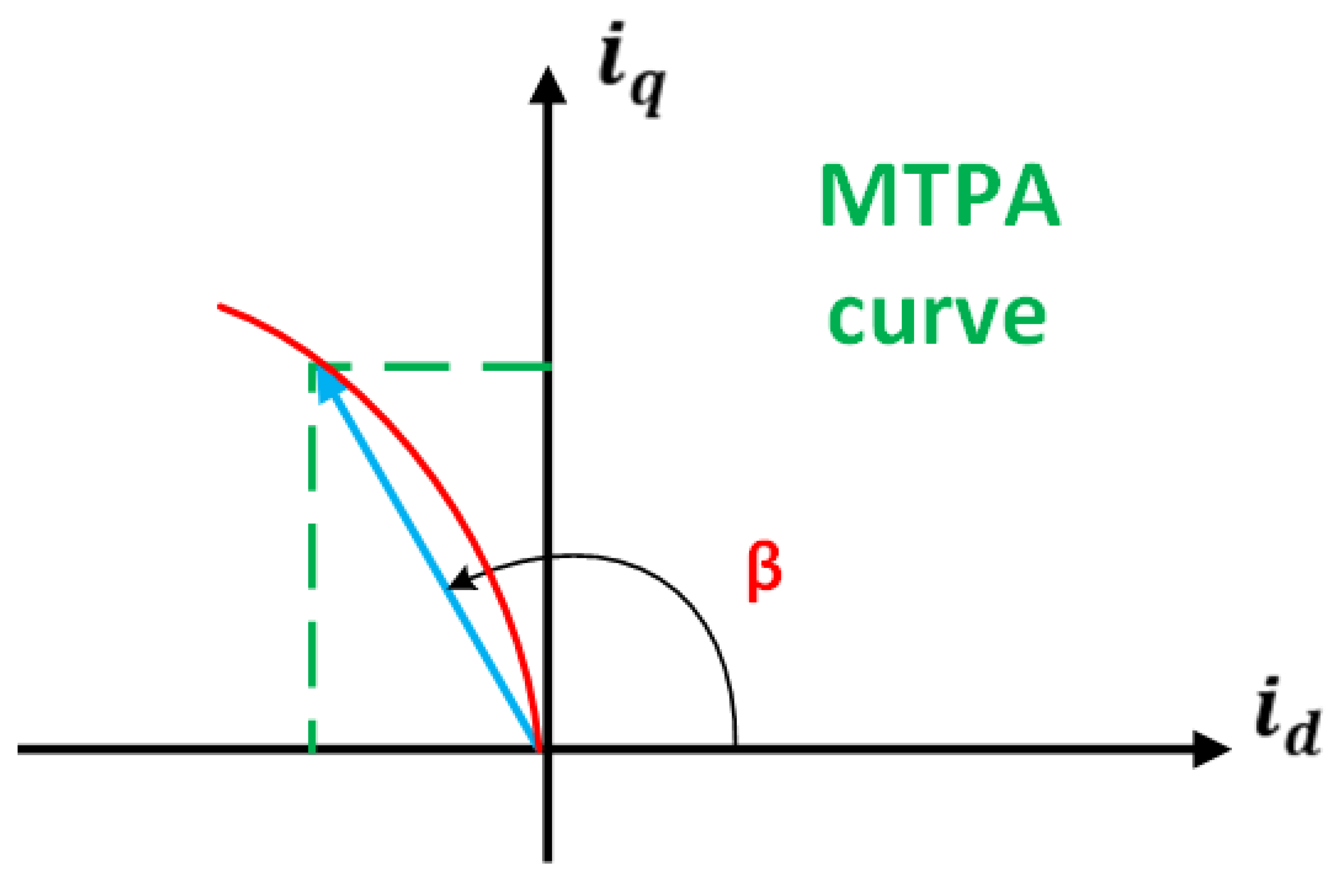
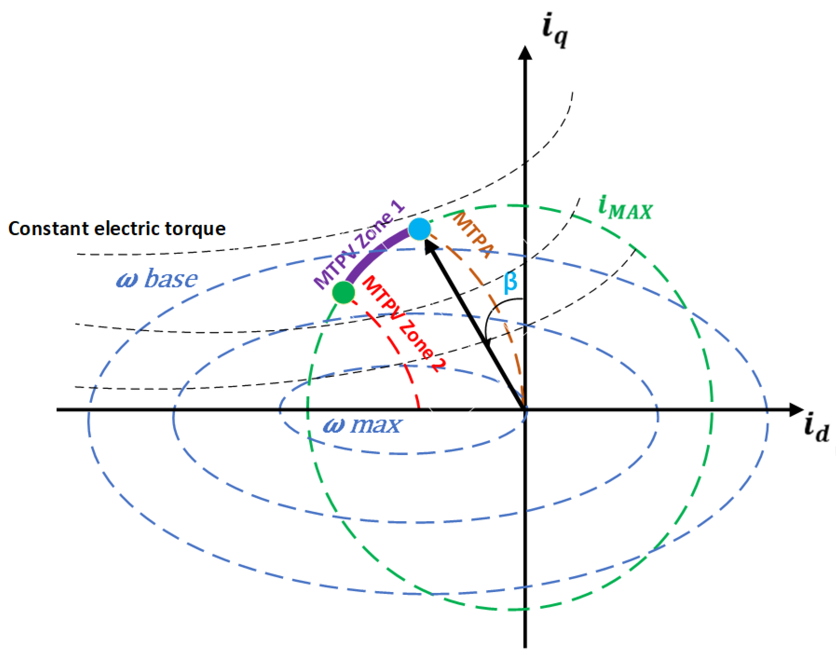
Therefore, it is crucial to have detailed control techniques that aim to use the twofold torque era mechanism in the most environmentally friendly way possible. Maximum Torque per Ampere (MTPA), which is sometimes used as a synonym for optimal performance or efficiency, is the term used to describe those tactics. Put another way, it is one of the fundamental ideas that the machine working at such setpoints ensures improved efficiency, reduced copper loss in the stator windings, and maximum torque generation with the least current consumption. It is important to note that these MTPA tactics are occasionally called maximum torque per current (MTPC). A d-q current reference frame guarantees that the stator current is used as little as possible to generate the most excellent torque. By decreasing the current force with torque or maximizing torque concerning the limited current, we can reach the MTPA region or condition. Torque generation has a degree of freedom by the pair of i d and i q , which can be used to reduce energy consumption. It is essential to consider how the current angle in the d-q plane changes regarding the torque generated. This is known as the MTPA angle, as shown in Figure 5, and the current phase angle β is represented by the current vector in polar coordinates [2].
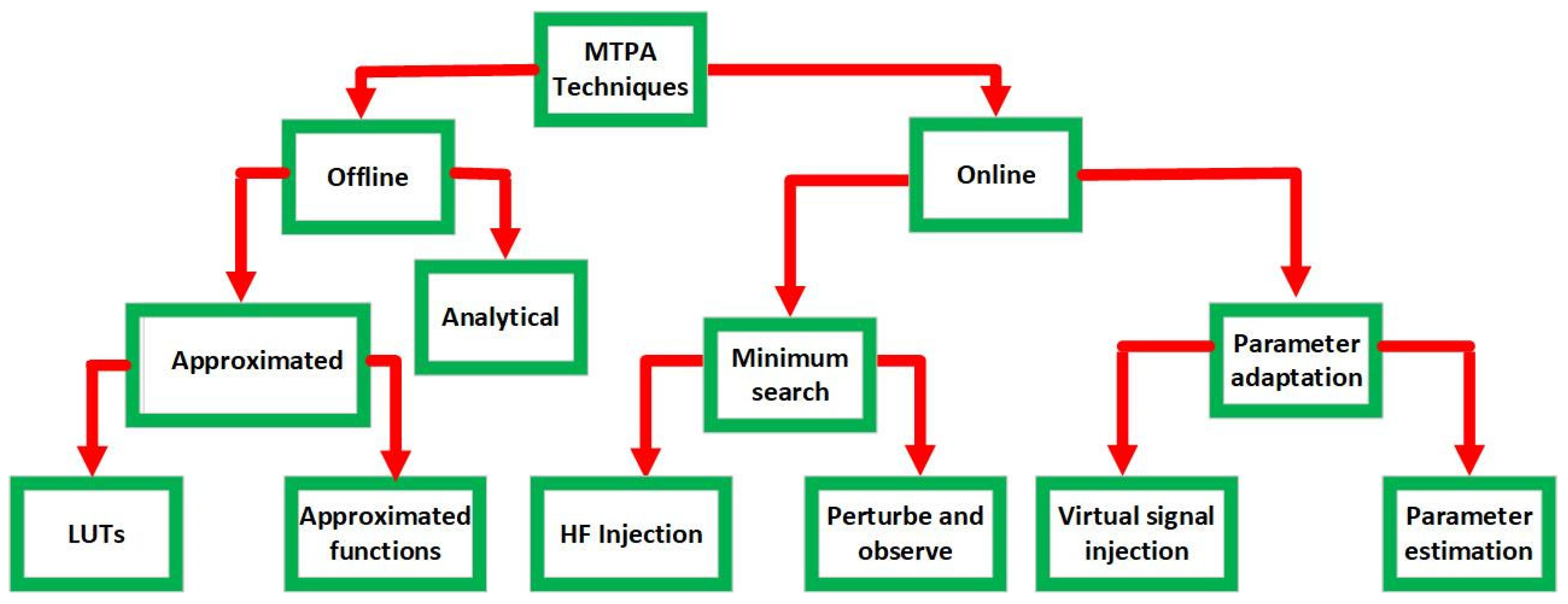
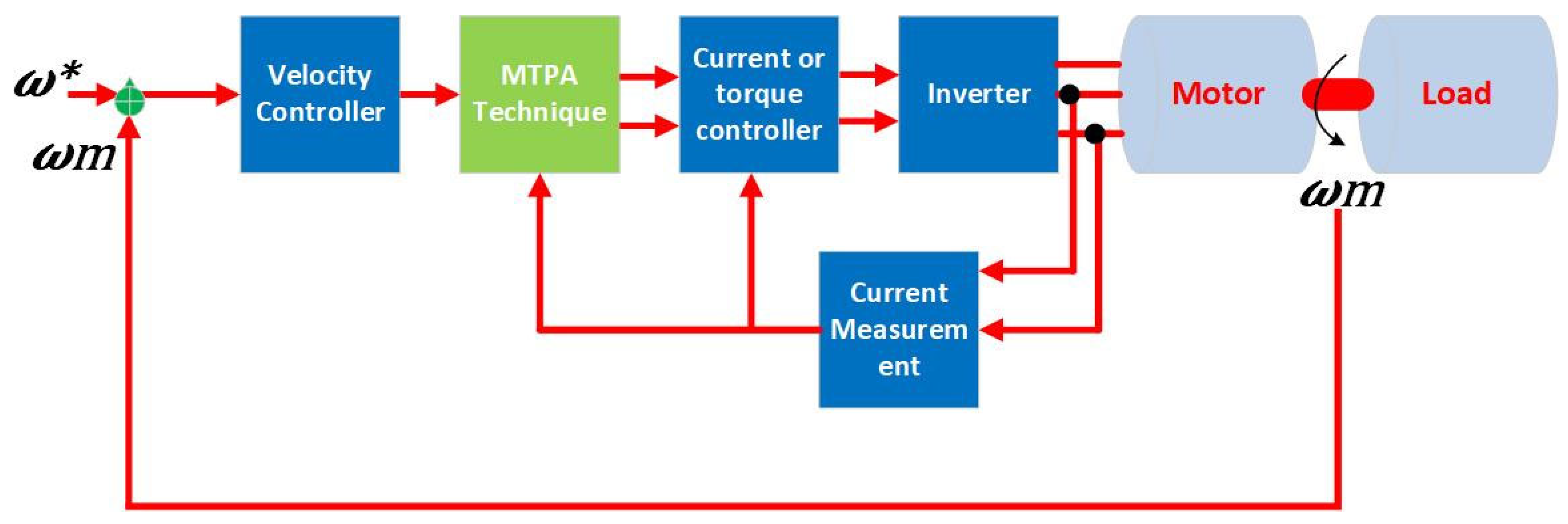
As shown in Figure 6, MTPA strategies can be divided into online and offline approaches. From this perspective, it is crucial to pay attention to how the MTPA depends on the machine’s settings [2]. A general diagram of electric drives using MTPA techniques is shown in Figure 7. On the one hand, there are several ways to implement MTPA as an online method, including processing the output of the regulated speed concerning a set of current and torque control loop references such as (FOC) and (DTC). Conversely, some offline MTPA methods are represented by Look-Up Tables (LUT) and analytical solutions [2,64,65].

4. PMSMs and Flux Weakening (FW)

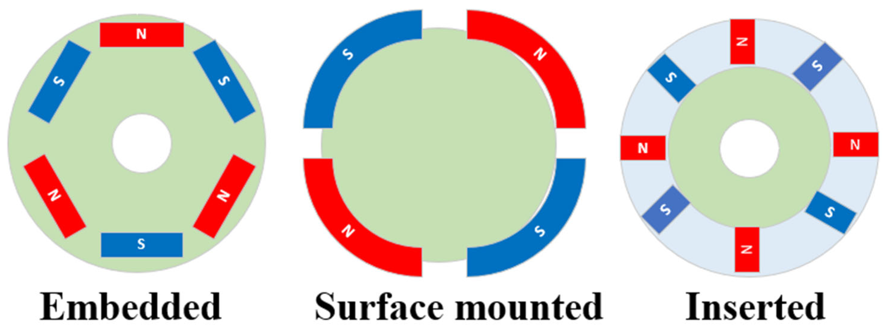
PMSMs are classified into two categories based on where the magnets are located on the rotor: interior permanent magnet synchronous machines (IPMSMs) and surface-mounted permanent magnet synchronous machines (SPMSMs). The permanent magnet is positioned on the rotor’s surface in the SPMSM, but it is buried deep within the rotor in the IPMSM [19,53,66]. This feature sets PMSMs apart because the placement of the permanent magnets provides greater protection against centrifugal forces, resulting in a robust construction. Various PMSM rotor machine types are depicted in Figure 8 based on the magnet positions. Furthermore, in the SPMSM, the reluctance torque is nearly zero due to the inductances L d and L q being roughly identical due to permanent magnets confronting the stator armature windings and air gap. On the other hand, the IPMSM’s total torque is made up of the reluctance torque and the load torque generated by the permanent magnet flux. The IPMSM’s mechanical structure contains a non-uniform gap that causes the inductances L d and L q to be unequal, a phenomenon known as cross magnetization. As a result, there is a high reluctance route because of the flux along the d-axis instead of the q-axis. This fluctuation in reluctance creates magnetic saliency, producing a reluctance torque. In terms of torque capability output, all these favor IPMSMs over SPMSMs [2,63,67,68,69,70].
Since PMSMs have a constant rotor flux, the flux of the stator can be weakened by delivering a demagnetizing current alongside the d-axis. This is necessary for high-speed operation in AC machines, which requires the right weakening for the flux. The optimal approach involves selecting the appropriate controlled vectors to maximize output torque while minaimizing stator flux. Maximum torque per volt (MTPV) is a control approach used in high-speed situations. It is complex to properly select all limitations and constraints, including current and voltage vectors [50,51,52,71,72,73].
When discussing electrical machines, saturation effects should be considered. Still, inductances are crucial because they determine the central portion of the machine’s behavior and the voltage and electromagnetic torque, which primarily and directly affect these machines’ dynamics, field weakening, and control precision.
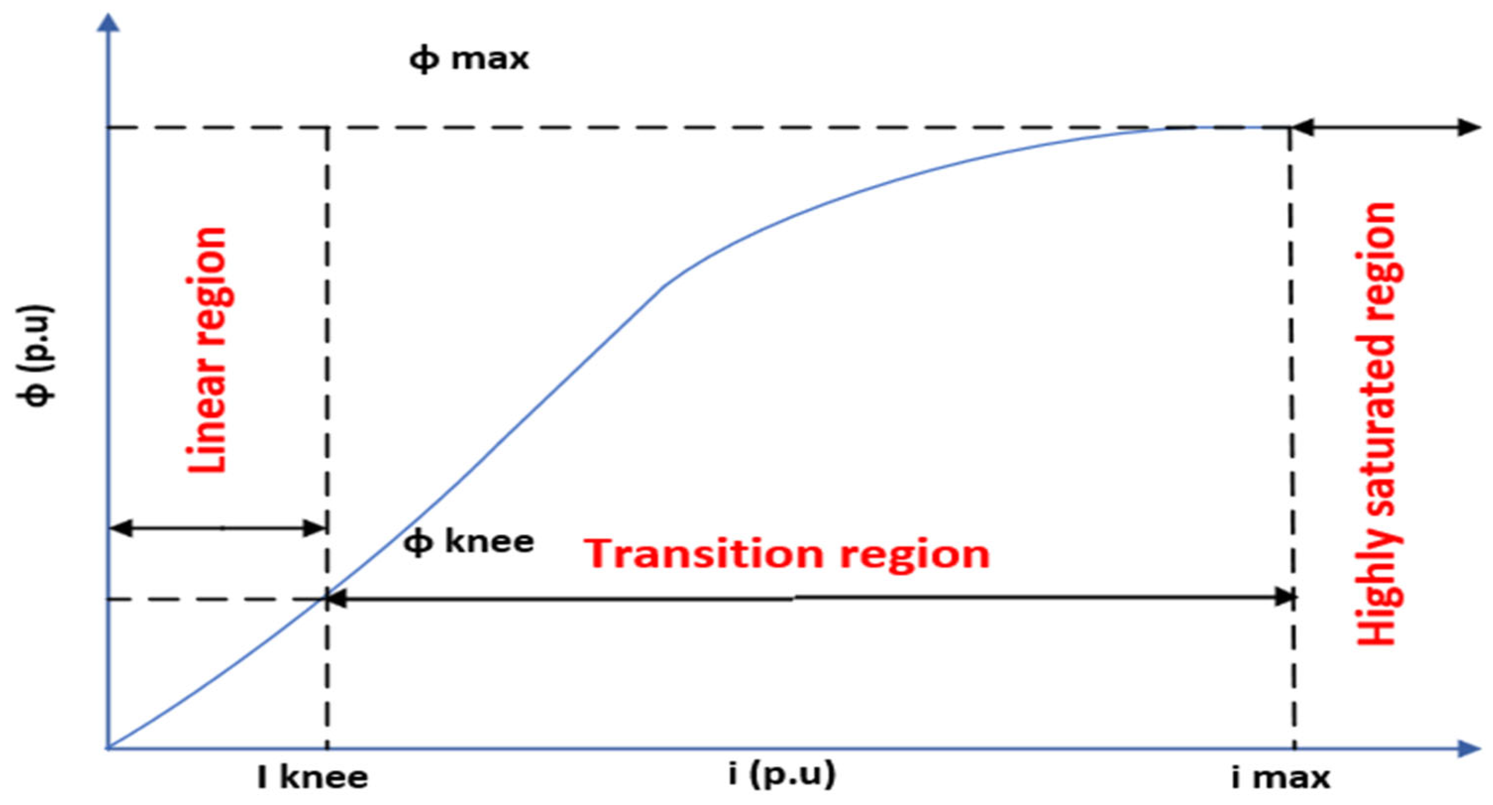
Put simply, the ferromagnetic core materials used in electric machines have a unique property that can become saturated as the flux passing through the core increases. In other words, when the overall flux, which depends on rotor and stator currents, increases in the electric machine, these ferromagnetic parts will reach a saturation point. This saturation effect occurs when the induced current increase does not proportionally increase the strength of the magnetic field [74]. This magnetic saturation effect is caused by inequality in inductances L d and L q in the IPMSM, known as (cross magnetization) and leads to a high nonlinear relationship between an inductor’s current and flux linkage [69]. This nonlinear inductor’s characteristic is divided into three regions, as shown in Figure 9 [2].
First, the flux–current relationship is linear with non-saturation existence when the excitation is low, meaning that the inductor conserves its unsaturated value. This part is called the unsaturated region. Subsequently, the saturation begins in the core when the flux value reaches a specific value; at this point, the relationship shifts to a nonlinear region, referred to as the knee point or (transition region) of the flux linkage; as the current increases, the inductor’s permeability decreases, lowering the flux linkage’s rate. This saturation significantly reduces inductance while continuing to increase the current. Finally, the flux is almost constant at its most significant point in the very saturated third zone [75]. The silicon steel cores work in the highly saturated zone to obtain high torque. Furthermore, as previously known, the inductance values L d     and L q cannot be fixed while the electric machine operates. Therefore, the motor model and the controller should account for this saturation effect to estimate the behavior of real-time simulation in the electric machine as accurately as possible [76].

4.1. Operation Limits

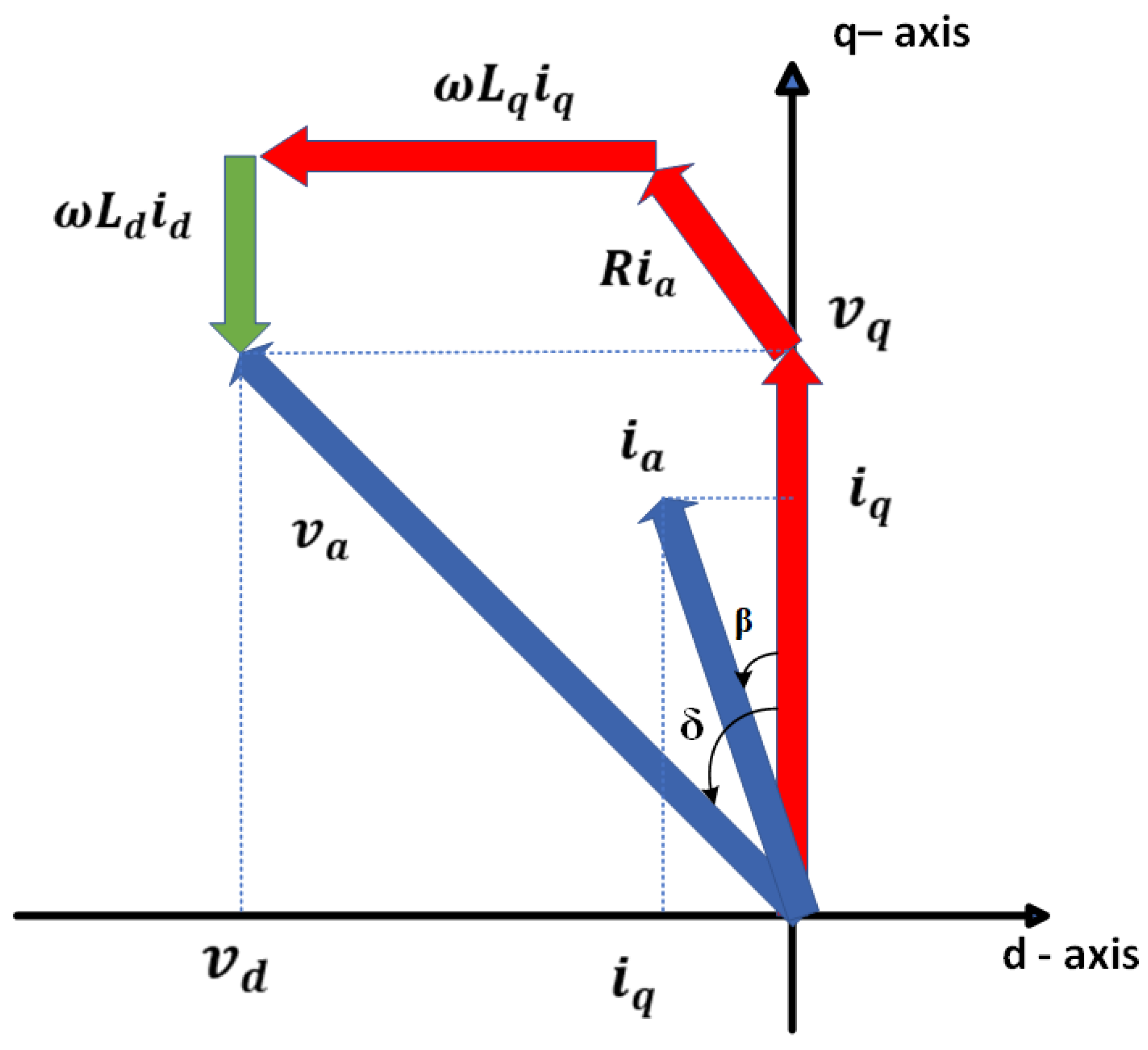
The permanent magnet synchronous machine’s phasor diagram, which is obtained from Equation (1), is depicted in Figure 10, where I s represents the current vector and V s represents the voltage vector [2]. The figure also shows the positive d-axis’s voltage angle δ and current angle (β). Several PMSM control methods based on the variables i d , i q , I s , and β have been documented in the literature [77].
The electromagnetic torque τ of PMSM, according to its mathematical model, obeys the Formula (6) below [58]. Where p is the number of pole pairs.
τ = 3 2 p L d L q   i d i q + λ i q    
Synchronous machines show certain operation speed and torque restrictions based on the available applied DC voltage and the inverter-rated current.
Electric drives are typically powered by a power electronics converter, which sets limits to maximize the output current and voltage from the inverter. The inverter’s output current, thermal dissipation and cooling methods are the motor construction-related aspects that determine the motor’s current limit of I m a x , as shown in this expression [2]:
i d 2 + i q 2 = I s I m a x
I m a x represents the maximum current for the source, inverter, and motor. The short circuit current I s c , another critical PMSM parameter, is equivalent to the flux produced by the stator’s winding current with the same direction and value on the d-q axis. This is the same as the flux linkage of the permanent magnets, which is written as follows [2]:
  I s c = λ L d  
The possibility of extending the speed-torque characteristic at higher speeds is determined by the power source, inverter, and thermal battery limits, which also determine whether I m a x is lower or higher than I s c . The voltage limits are calculated by ignoring the equivalent winding resistance R a in (1) and considering the Space Vector Pulse Width Modulation (SVPWM) strategy as shown below [2]:
v d 2 + v q 2 = V s V m a x
( I s c + i d ) 2 1 L d 2 + i q 2 1 L q 2 = V s   m a x ω 2
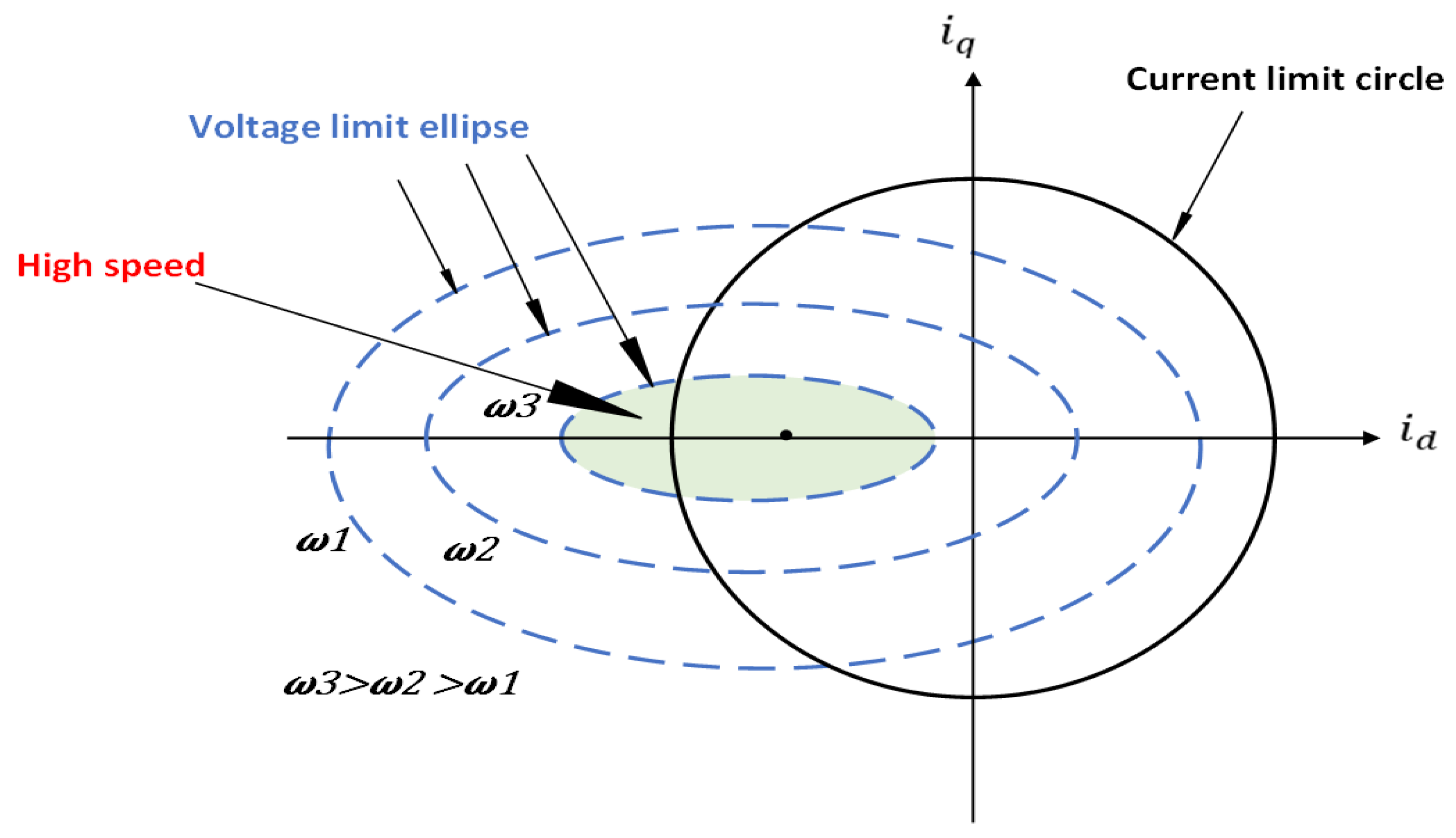
All operational points where the terminal voltage does not exceed the maximum voltage are enclosed within the ellipse formed by the voltage restrictions within the   i d and i q   plane, where Vs max is the power source’s voltage [78].
These synchronous machines must be controlled to satisfy the constraints simultaneously within the voltage ellipse and current circumference [79]. In addition, the current limits, as stated in (7), result in a curve that includes a circumference in the d-q plane of stator currents with a radius I m a x . Similarly, an ellipse with a reduced radius exists for the voltage limit Formula (10) when the electric machine’s speed increases. Current and voltage limits in the d-q current plane are shown in Figure 11 below [2].
The function of the reference torque and mechanical speed represents the various current trajectories obtained while considering these limits and constraints. Consequently, two ideal paths exist for interior PMSM where ( L d L q ) and service mount PMSM when ( L d = L q ) of the stator currents in the d-q plane. Different ideal current trajectories as a function of mechanical speed and the reference torque can be derived by considering these limitations.
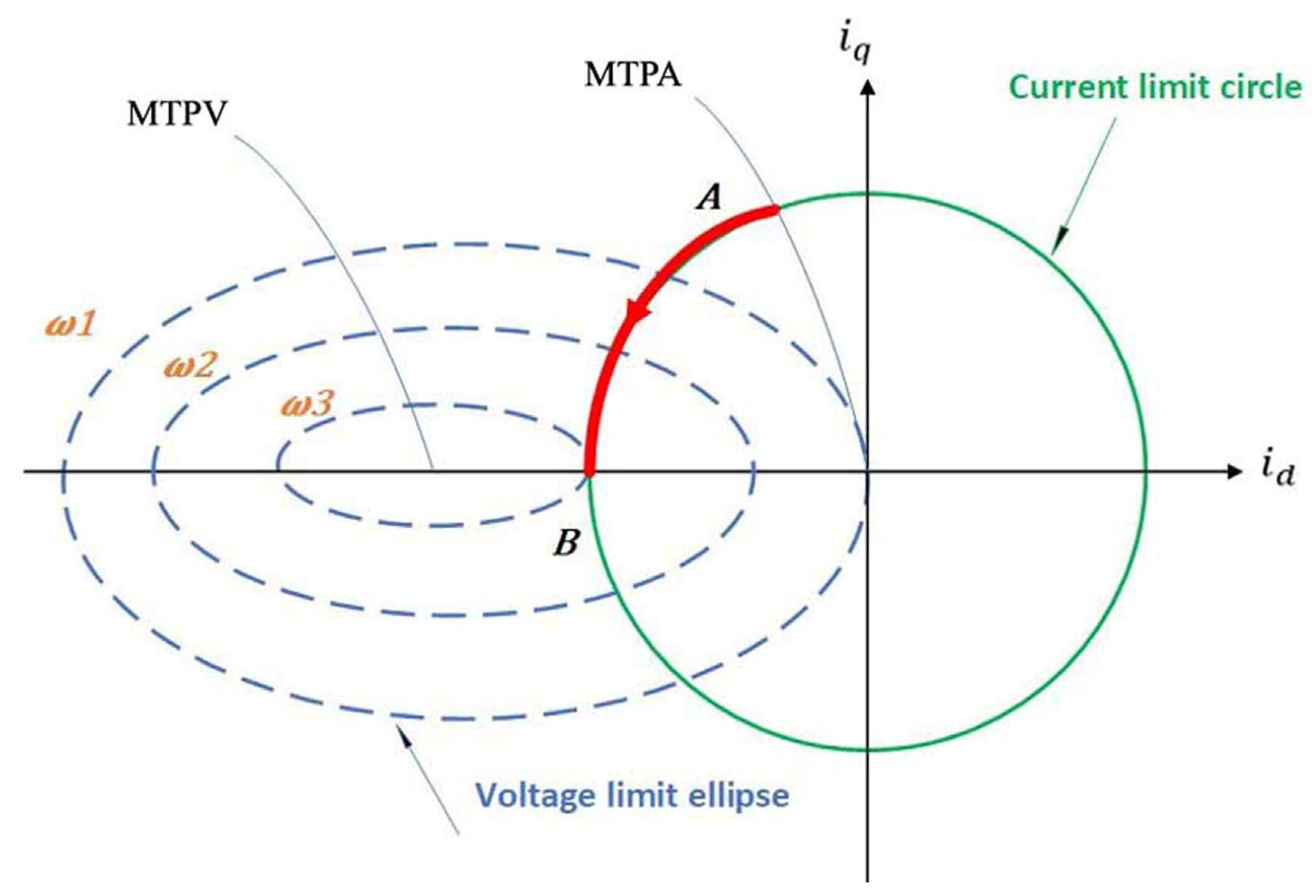
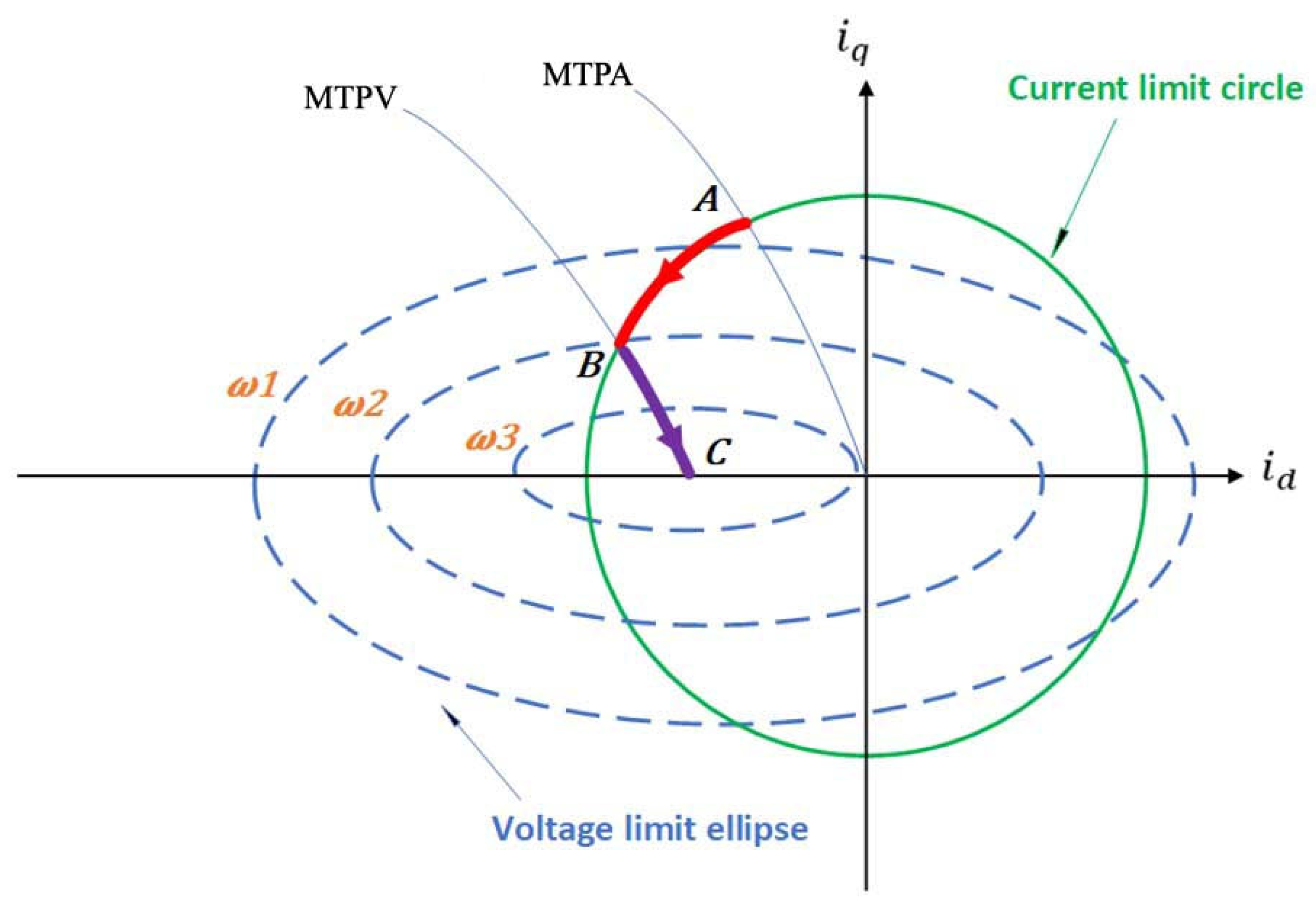
The voltage limit ellipse center occurs inside the current limit circle when ( I m a x > I S C ) , and the maximum available speed becomes theoretically unbounded as illustrated in Figure 12 and Figure 13. In contrast, when the voltage limit is outside the current limit circle, as in Figure ( I m a x < I S C ), the maximum speed is finite, with the voltage limit ellipse center ( i d , i q ) = (− I S C , 0) equal to (−  λ / L d , 0) as defined in (8).
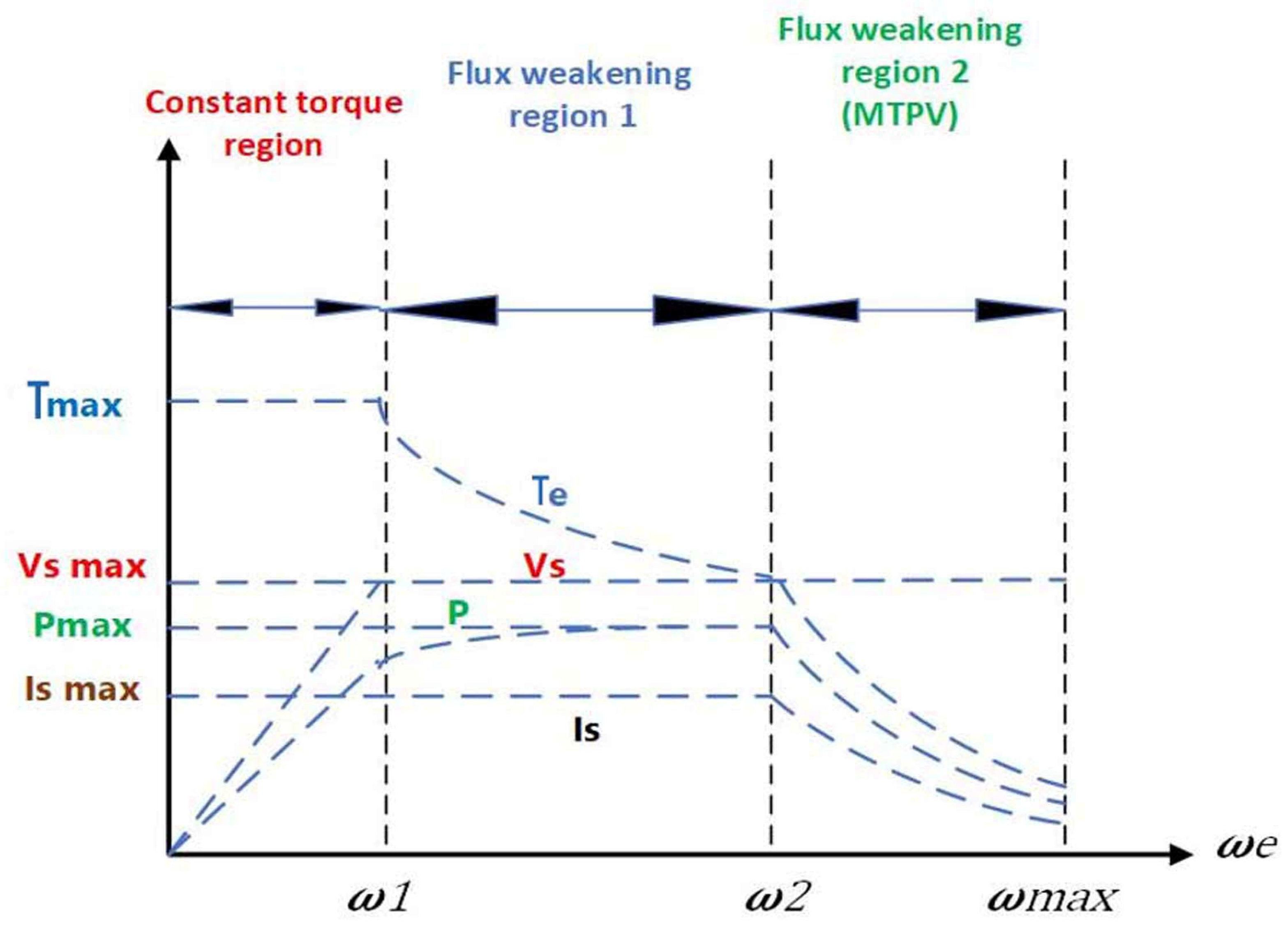
We have distinct operating areas for synchronous machines concerning the defined voltage in (9) and current in (7). The Maximum Torque per Ampere (MTPA) zone inside the constant torque, field-weakening (FW) region while under constant power while adjusting the torque, and deep field-weakening (FW) region with continual voltage at MTPV are illustrated in Figure 14 [2,80,81].

4.2. PMSM Back Electromotive Force (BEMF)

There is a proportional relationship between the Back Electromotive Force (BEMF) and the mechanical speed generated by the magnetic field of the permanent magnets as the machine rotates. In general, two distinguished zones during the operation of the PMSM depend on the voltage drop of the stator winding, the maximum voltage and current supplied to the machine, and the value of the BEMF. The machine’s first operating zone, the Low Back Electromotive Force (LBEMF), occurs when the BEMF value plus voltage drop one is less than the total maximum voltage the inverter can gather. But when the speed keeps going up, the machine reaches the traction inverter voltage limit and moves into the FW zone. To improve speed while maintaining torque applied to the shaft, any voltage supplied to the electric machine must be managed and modified within the current passing through the stator windings to be synchronized with the present DC voltage.
Some strategies could be applied at the LBEMF, such as Constant Sator Flux Control (CSFC), Constant Torque Angle Control (CTAC), MTPA, Unit Power Factor Control (UPFC), and other methods, as the authors compare in [18] (pp. 307–330). Again, one of the most used strategies for EV applications is the MTPA strategy. As we discussed, this strategy minimizes the current needed to achieve the maximum demanded torque to satisfy the need for electric vehicles. Minimizing the cross-sectional areas of the conductors leads to the maximum output efficiency of generated power.

4.3. Maximum Torque per Voltage (MTPV) Region

For EV applications, the reduction in ampere–volt, range of constant power, proper rating controller, multiple mechanical gear systems, and robust compatible vehicle design can all be achieved using the FW strategy [82]. In some applications, there is a need for a drive with no fixed upper speed limit. Such applications require no upper limit speed to achieve unlimited speeds under lossless conditions.
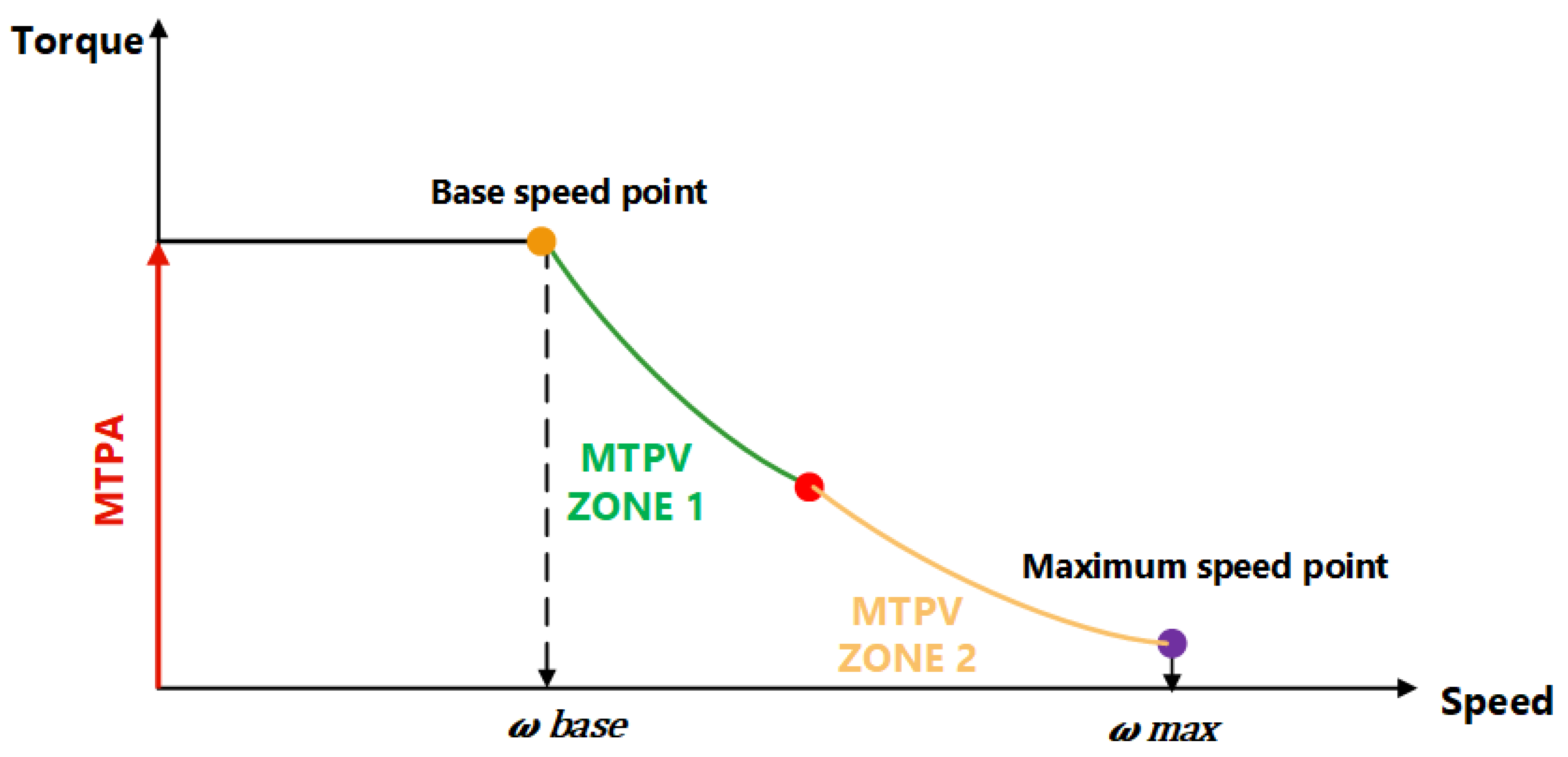
To meet this case, these drives should obey the maximum torque per volt (MTPV), also known as the maximum torque per flux (MTPF). The operation of the permanent magnet machine here occurs in what is called the deep FW region. This zone is achievable only when the condition ( I m a x > I S C ) is satisfied. Suppose there are no losses or mechanical limitations considered in the ideal case. In that case, the electric machine delivers torque into an unlimited speed range, while in the case when the speed is finite, that happens due to iron, mechanical, and copper losses. However, in the MTPV, the torque production capability is at its maximum for a constant stator voltage value. Thus, more power could be achieved during the deep FW performance in this MTPV region.
This algorithm is a crucial control method for obtaining extra power from the same electric machine. In other words, in the MTPV region, when the machine operates within a maximum speed defined by voltage and current limits for a specific speed, the torque obtained is higher than that which we can achieve if an algorithm considers just the current and voltage limits.
The MPTV trajectory is defined as the track when maximum torque is achieved at the minimum current, considering the voltage limit for PMSM machines. In this condition, the references of the current are derived based on the intersection of tangents between the shrinking ellipse of the voltage and the curve of the torque where τ δ = 0 ; the MPTV current formula is typically derived from the voltage limit ellipse equation under steady-state conditions as shown in (11), where I s c is the short circuit current magnitude and β is the current vector angle in the d-q frame [42,83,84,85]:
  I M T P V = I s c c o s ( β )  
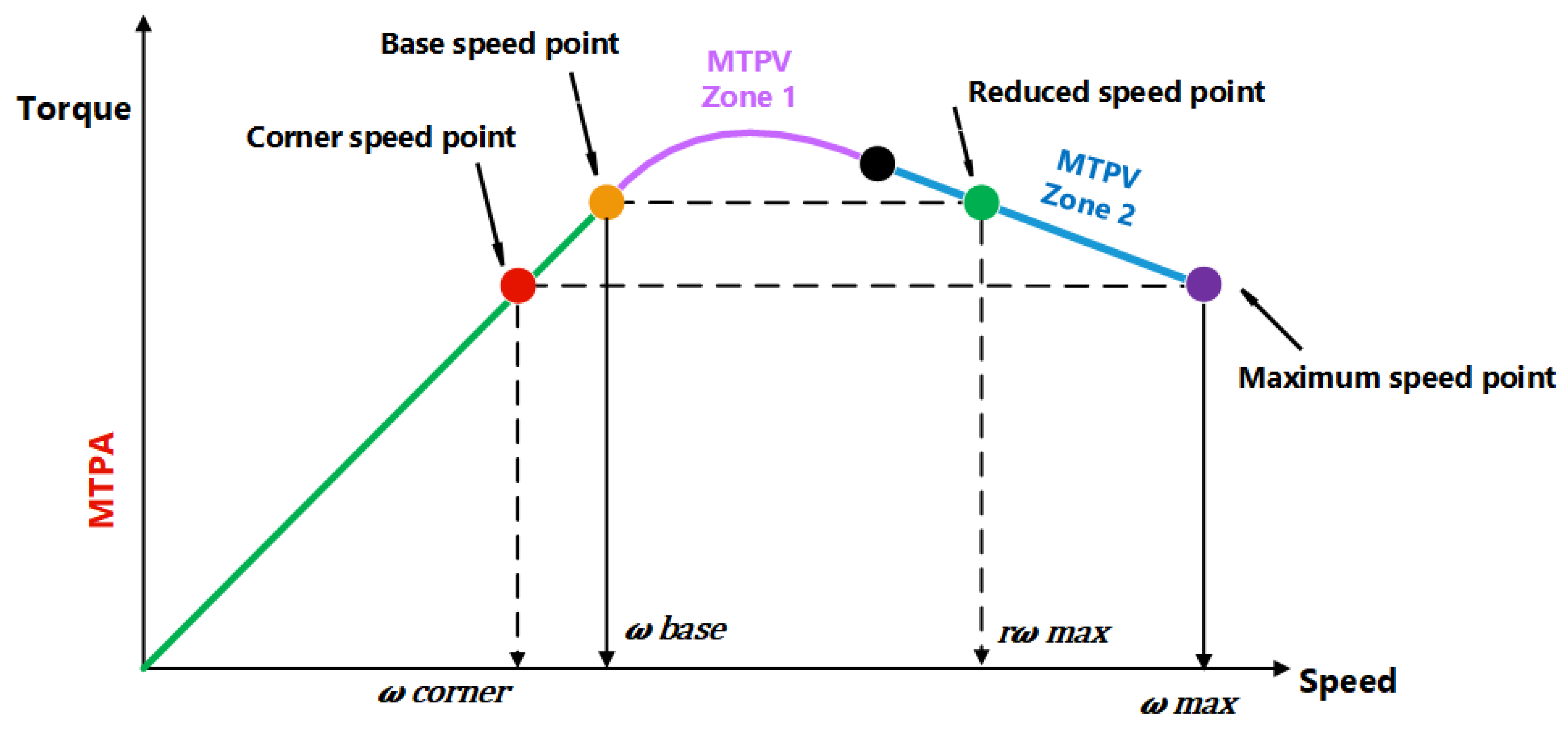
Figure 15, Figure 16 and Figure 17 represent the MTPA and MTPV within FW regions in the high-speed ranges via the torque–speed characteristics curve, trajectory of current vector working points in the i d - i q plane, and power–speed characteristics curve, which shows how the mechanical power of the machine can be controlled in relation to a specific used point of speed [79,86].

5. Flux-Weakening Control Methods

In [87,88], FW methods are categorized and organized into feedforward and feedback types. These model-based techniques calculate the most efficient current trajectories for the wanted torque and flux at each speed range by utilizing the current, DC voltage, and machine parameters, so the q-axis reference current is determined from torque-speed command. The d-axis reference current could be obtained in various speed ranges as a function of speed from voltage and current limits.
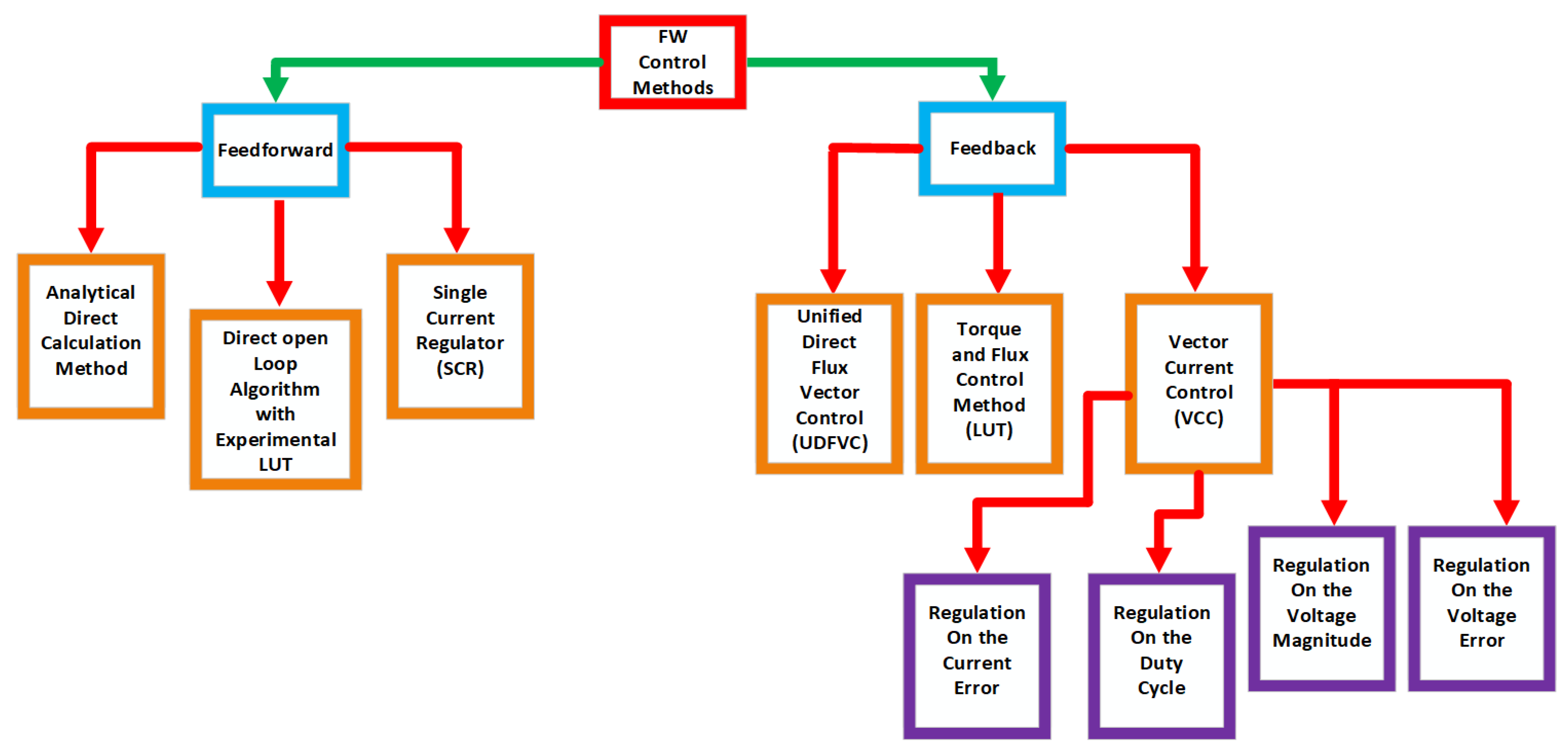
On the feedforward methods side, these strategies mainly depend on the operating conditions and the machine parameters, with good results represented by stable and better transient responses. On the contrary, feedback methods utilize a suitable control loop to regulate the voltage from the inverter. The d-axis reference current is aligned to follow the voltage limit as the speed increases. These methods are efficient, mainly when they do not rely on the motor’s parameters. However, closed-loop voltage controllers are bad and have complex benefits because of their operation complexity [89]. Figure 18 shows a block diagram of FW control methods, as presented by the authors in [90], who already classified several FW control strategies.
To fully understand FW capacity in this study, this paper compares and contrasts several control systems for FW operation, highlighting each strategy’s primary advantages and disadvantages.

5.1. Analytical Direct Calculation Method

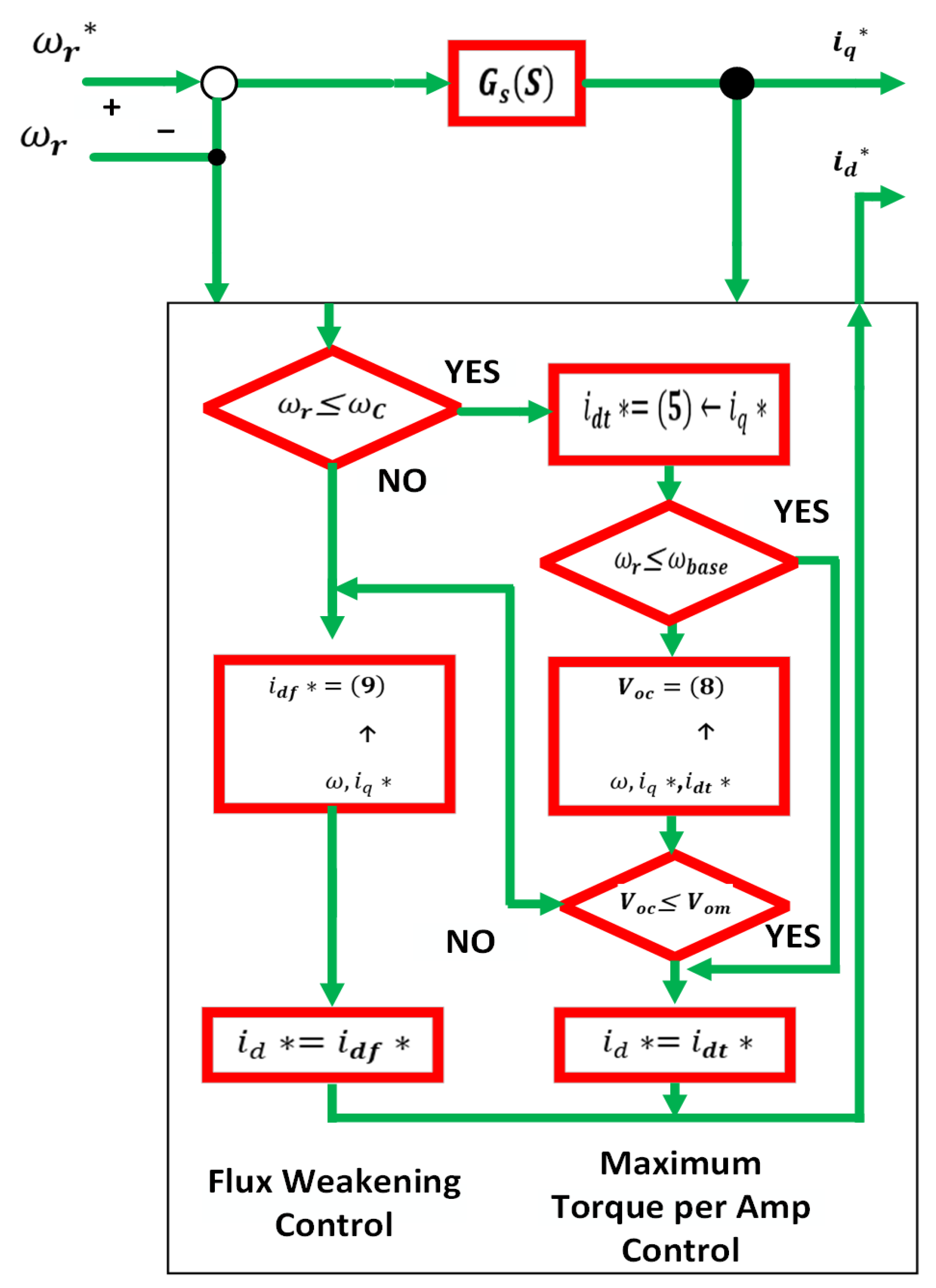
The analytical direct calculation method could be used in both LBEMF and FW regions using some equations to produce the needed d and q-axis reference currents [83,89,90,91]. These reference currents can be calculated by considering the current limit, voltage limit, actual speed, and torque limit of the used machine. In the case when we are working below the speed rate, then the operation is conducted in the LBEMF with the MTPA algorithm. If we work at a higher speed than the base one, the machine works in the FW region within the voltage limit.
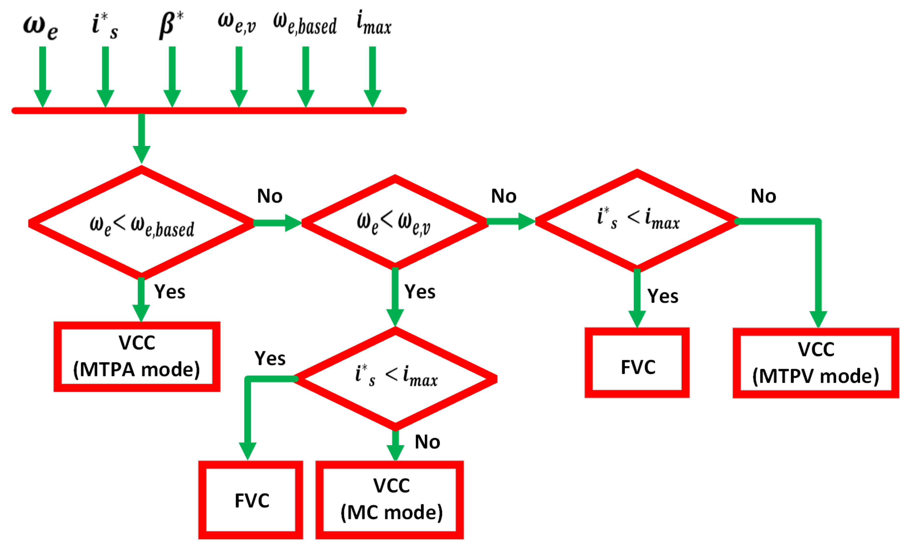
Authors in [91] have mentioned that these analytical method equations should have some assumptions and considerations, such as neglecting the core magnet saturation effect, ignoring the magnetic stagnant and vortex losses, and having a symmetrical three-phase sinusoidal electric current. Primarily, the PID speed controller generates the q-axis reference current. In contrast, the d-axis reference current is calculated from the characteristic equations of the electrical speed of a PMSM. Figure 19 presents the flowchart diagram for current vectors and the transition of both MTPA and FW modes [83].
In [92,93], the authors mentioned some disadvantages of this algorithm related to the machine’s parameter variation, which makes this strategy susceptible in addition to the excessive time required for d-q axis currents calculation when dealing with an IPMSM; also, because of ignoring the magnetic saturation effect, such a condition makes this control method to be unstable.
On the other hand, in [94], a new methodology was introduced with reduced execution time for this analytical method, considering the stator resistance to avoid complexity and using Look-Up Tables LUTs or adjusting polynomials numerically. Also, as in [95], this analytical method is a good choice for high-power motors with small stator resistance. A combined flowchart was performed with a PID controller to calculate the d-axis reference current, considering the reference torque value, which can work in the MTPV region [96]. Another flowchart tree was proposed by S. Wang in [97] to determine the working zone according to the known speed, current, and reference torque in addition to the Tylor series First-order Jacobian matrix with Second-order Newton–Raphson method, an approximation utilizing iterative form to calculate the reference d-q axis current and, in addition, considering a magnetic coupling with nonlinear inductances applied through LUTs.

5.2. Direct Open-Loop Algorithm with Experimental LUT

The Direct Open-loop algorithm depends on Finite Element Analysis (FEA) Look-Up Tables and some experimental results. These tables store the relationship between the maximum permissible flux linkage with d-q current references and the torque setpoint.
In this strategy, the most critical factor required to calculate the current references is offline LUTs, while there is no need to use mathematical equations. Torque, flux linkage related to d-q currents, the minimum value between the maximum flux regarding the real electrical speed, and the amount of the optimal flux according to the torque; all these setpoints give the best extension from the base speed [98,99]. The most important pros of using LUTs for calculating current references is that they rely on variable inductance because of the cross magnetization and magnetic saturation effects due to non-uniform airgaps, as discussed before and mentioned in [69]. This makes the traction inverter follow the torque reference all the time without considering the magnetic saturation of the sheet. On the other hand, one of the primary cons of LUTs is its large experimental setup, which needs a sizeable memory storage for these tables in the speed-torque in the traction inverter. Furthermore, the time consumed with perilous machine tests during this algorithm should be considered.
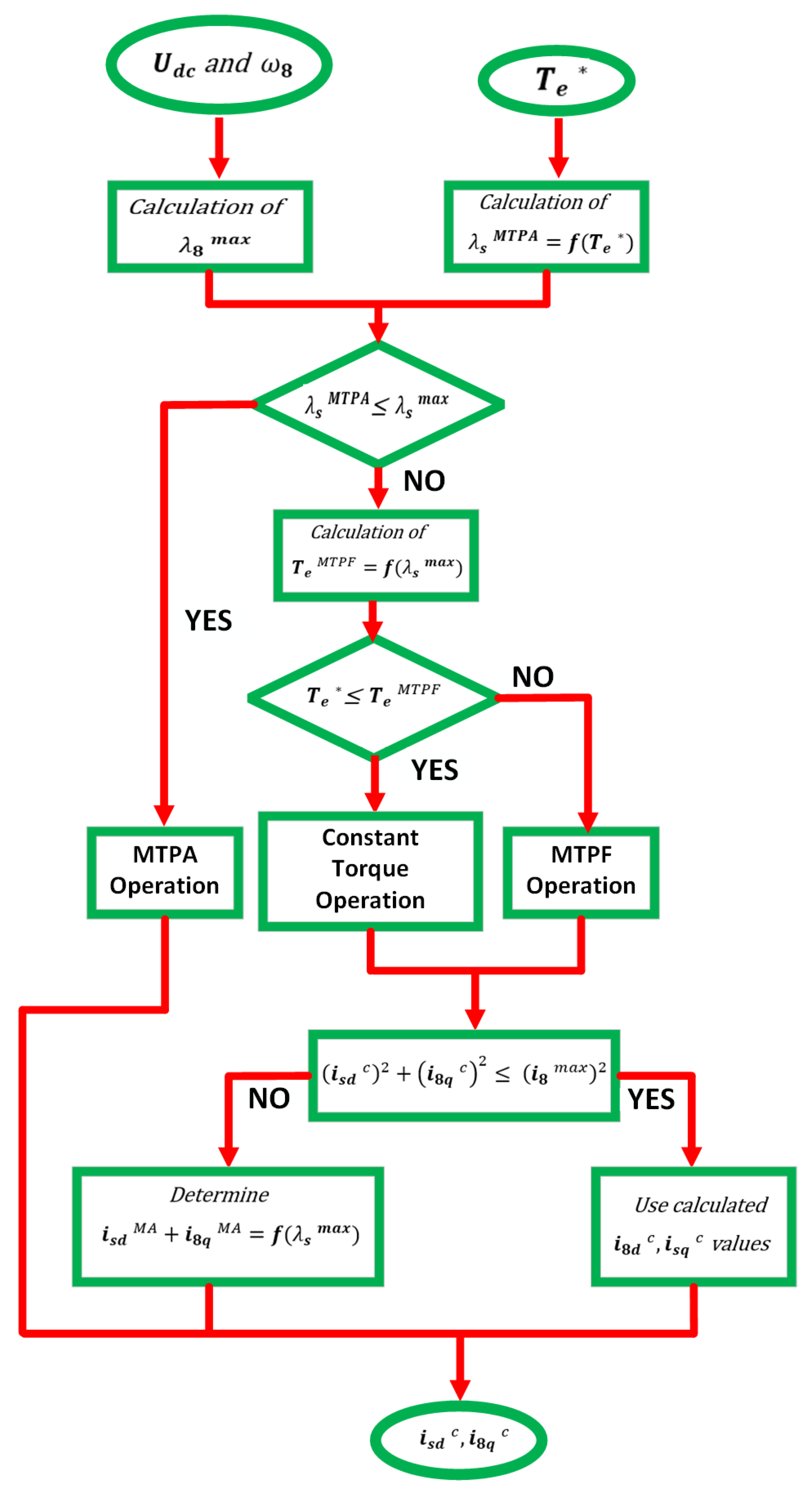
Additionally, authors in [99] affirm the LUT control technique that uses only points on the rims of the operation area, which maintains a good level of precision and leads to minimizing the memory storage needed in this method. Moreover, they use the Newton–Raphson method without considering the saturation effect to determine the d-q currents.
For more accuracy, extra LUTs must be used. To guide the reader through this, Figure 20 clearly illustrates the block diagram of the Proposed LUT control algorithm [99].

5.3. Single Current Regulator

The Single Current Regulator (SCR) operates in the FW region, relying on the unique current controller regulation. However, in the deep FW operation zone, two current controllers may conflict and cause instability for the system, making the voltage exceed the minimum voltage applied in a transient and steady state. This algorithm switches between LBEMF and FW zones. The transition between the two regions depends on the maximum permissible amount of voltage, which is related to the DC voltage and the way of switching. In the FW zone, a closed speed loop generates the d-axis reference current while the q-axis voltage is fixed. However, the switching within the base speed d-axis current is higher than its equivalent in the MTPA zone. The SCR in the LBEMF zone works only in the MTPA region, and the d-q axis currents are controlled independently. Generally, the speed PID controller defines the d-q current setpoints for the MTPA equation [100,101,102].
However, this algorithm changes its control technique when speed increases to enter the FW zone. The torque setpoint at the speed controller output is multiplied by constant K to calculate the d-axis current. This constant has a negative value because flux linkage and the demagnetized current are always in the opposite direction. The significant advantage of the SCR method is the absence of conflict between the d-q axis controlling current in the FW mode., which makes saturation easier when the current controllers operate near the maximum voltage value.
On the contrary, the main disadvantage of the SCR is the analytical switching between low and high speeds, as it complicates the transition between the LBEMF and FW regions. Additionally, since the d-axis current is controlled directly, there is no guarantee for the current value limit, which makes this method’s stability very sensitive to the controller parameters [92,93]. Authors in [102] have developed the SCR strategy with Voltage Angle Control (VAC) for deep FW operation to sidestep the conflict between the d-q axis regulators. Figure 21 shows the block diagram for this proposed method (the Authors defined β as the voltage angle in this strategy).
In [101], an estimation of the q-axis reference voltage was developed, which depends on mathematical torque-speed setpoints according to 2D-LUT. They support the idea that it is time-consuming to find the best q-axis reference current using the torque-speed variables while neglecting the saturation effects. Moreover, they found that the phase current is too small compared to the original method in simulation figures, and the DC voltage is a better choice to use in the FW operation region.

5.4. Unified Direct Flux Vector Control (UDFVC)

This method works inside the stator flux coordinates, where the d-axis voltage directly controls the stator flux amplitude. The q-axis current components simultaneously control the speed–torque setpoint. This control algorithm differs from the others because it is based on the stator frame rather than the rotor frame [103]. The load angle (ϕ) is the stator flux linkage’s phase angle concerning the rotor flux. The type of motor determines the angle’s limit, while the motor itself determines the precise value. Dedicated no-load tests with trial errors within the specified range can be used to assess it. A PID regulator that regulates the d-axis current based on angle load error sets the traveling over the base speed.
This control technique needs three PID controllers for controlling:
  • q-axis current;
  • flux linkage magnitude;
  • load angle limit at high-speed ranges.
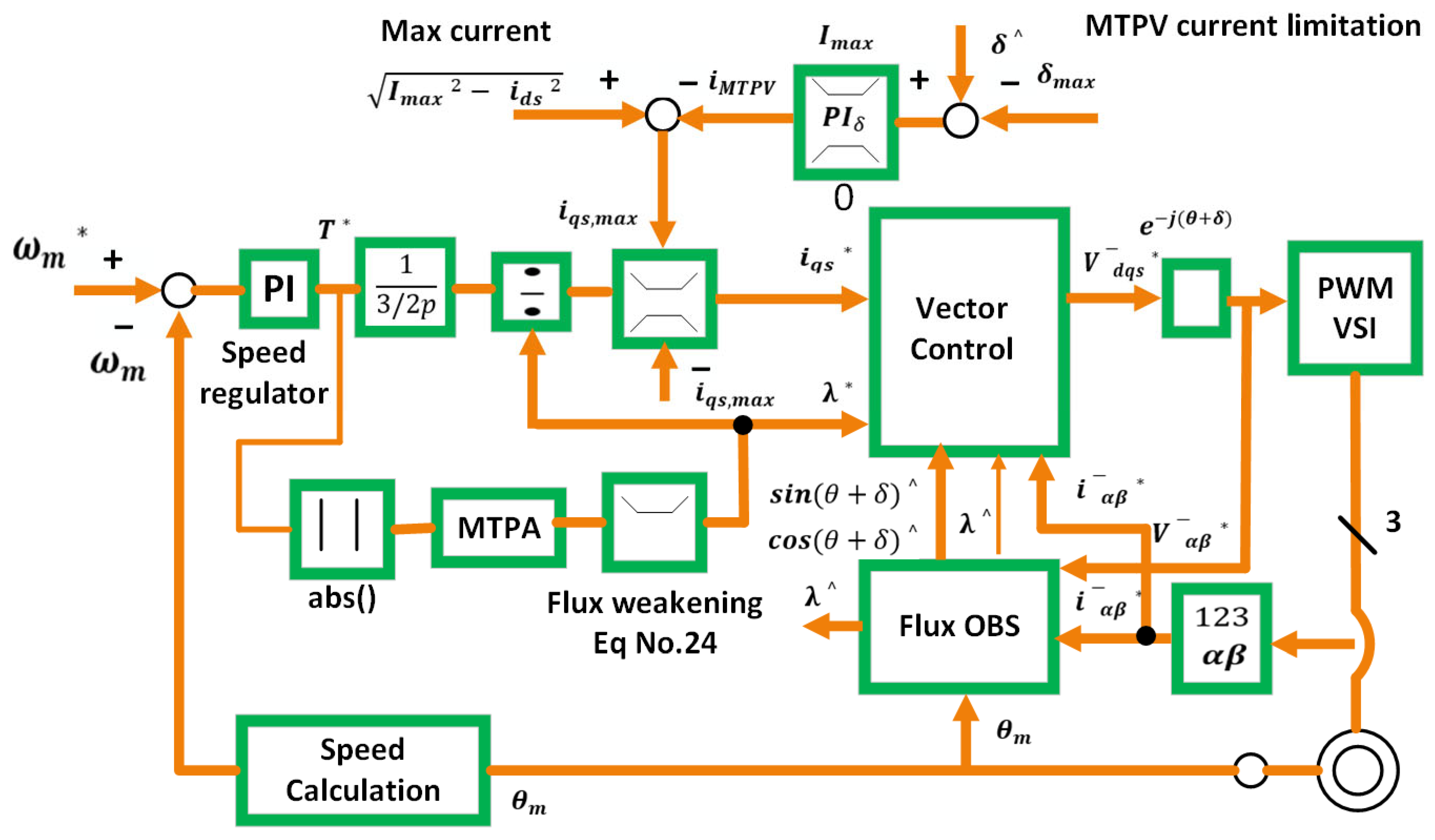
Figure 22 depicts the proposed block diagram of this control algorithm. It shows the estimated flux linkage, current magnitudes, and the load angle in the αβ-axis voltage. This algorithm considers the MTPA torque and the MTPV equation to determine the q-axis current and the flux linkage. One of the main advantages of this strategy is that it is appropriate for many types of AC machines, such as PMSMs, SyRMs, and IMs. Direct flux control by one regulation channel to the torque setpoints is presented in Ref. [53]. This method offers a nice combination by using only one current regulation channel for the torque setpoint, which makes it possible to achieve the current limit and FW operation directly.
On the other hand, a significant disadvantage of this control method is that the required flux observer mainly depends on the machine parameters. Hence, any mismatch between the real and the estimated parameters leads to error estimation in the steady-state torque and flux estimation error in the low-speed range. Moreover, it is a dependable bench test method, especially when trying to experimentally find the maximum load angle, as in [93].

5.5. Torque and Flux Control Method with (LUTs)

The Torque and Flux Control (TFC) using Look-Up Tables (LUT) joins a closed speed loop through a current PID controller and an offline table with a feedforward control. As the authors mentioned in [104], regarding Direct Torque Control (DTC), this strategy decreases the flux ripple and torque, unlike the classic DTC method, which uses the switching table and the hysteresis controller [104,105,106,107,108,109,110,111,112,113,114,115].
The variable flux linkage, which operates from the MTPA value, regulates the voltage, leading to a transition over the base speed. This methodology uses 2D-LUTs to calculate the setpoints of the d-q axis current from flux linkage and torque readings. An additional 1D-LUT is utilized for the base flux linkage calculation, considering the torque setpoint in the MTPA zone. When the electric speed increases, the absolute allowable flux linkage decreases, and the feedback root, which is proportional to the magnitude of the voltage applied, controls the operation of the FW. This strategy considers the effect of magnetic saturation to be the same as that of the direct open-loop method.
A new methodology was presented in [111] to obtain the 2D-LUT through the d-q reference currents and the flux and torque setpoints. The authors also claim that a voltage control loop is optimized for rotor speed-increasing situations to meet the demand for fast dynamics.
Several shortcomings of traditional solutions have been counted in [107,109], such as:
  • Dynamic torque control;
  • Seamless transition between FW and Six-Step operation;
  • Current harmonics because of the Six-Step which generated the current ripple for the inverter’s DC link capacitor and reduced its lifetime.
Additionally, the authors depend on the fact that the PID current controllers can avoid the integrator windup. The current reference modification between the voltage reference and that obtained from the regulators by the over-modulation is performed using a back calculation technique. Another disadvantage of this traditional strategy is the large memory required to save the 2D-LUTs and 1D-LUTs for many results. Furthermore, this method may cause a conflict for the controller in the FW when they operate simultaneously. An anti-windup strategy for the current controllers was proposed in [107], which separates the feedback control into two separate and independent PID controllers for q-axis voltage and the other one for d-q-axis voltage.
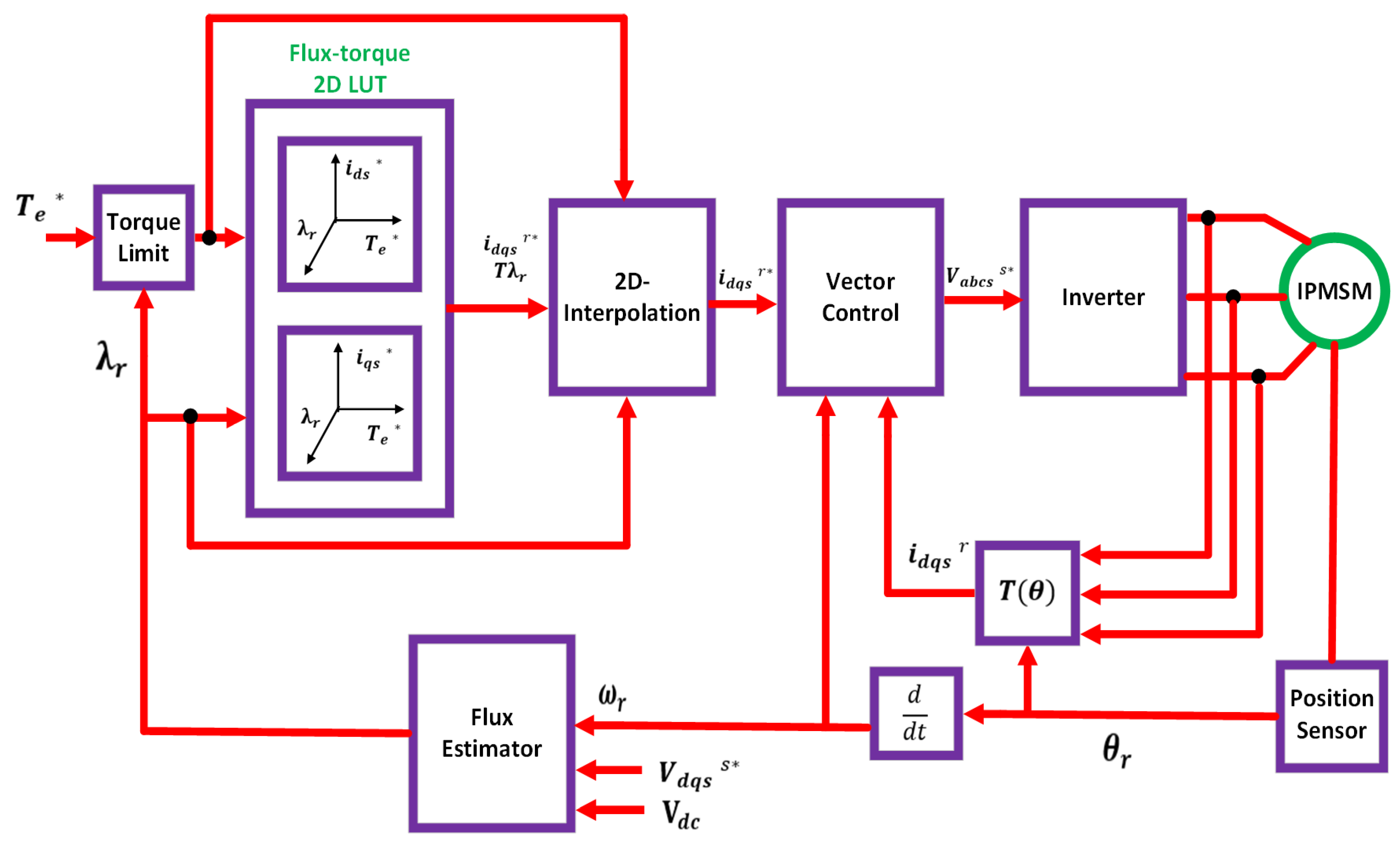
In the torque flux plane-based approach proposed by the authors in [115], two PID controllers control the machine’s torque and flux. Rather than using 2D-LUTs, a curve-fitting strategy is employed to display the torque-speed and flux correlations. The torque-flux control approach with 2D-LUTs is shown in Figure 23 [116].
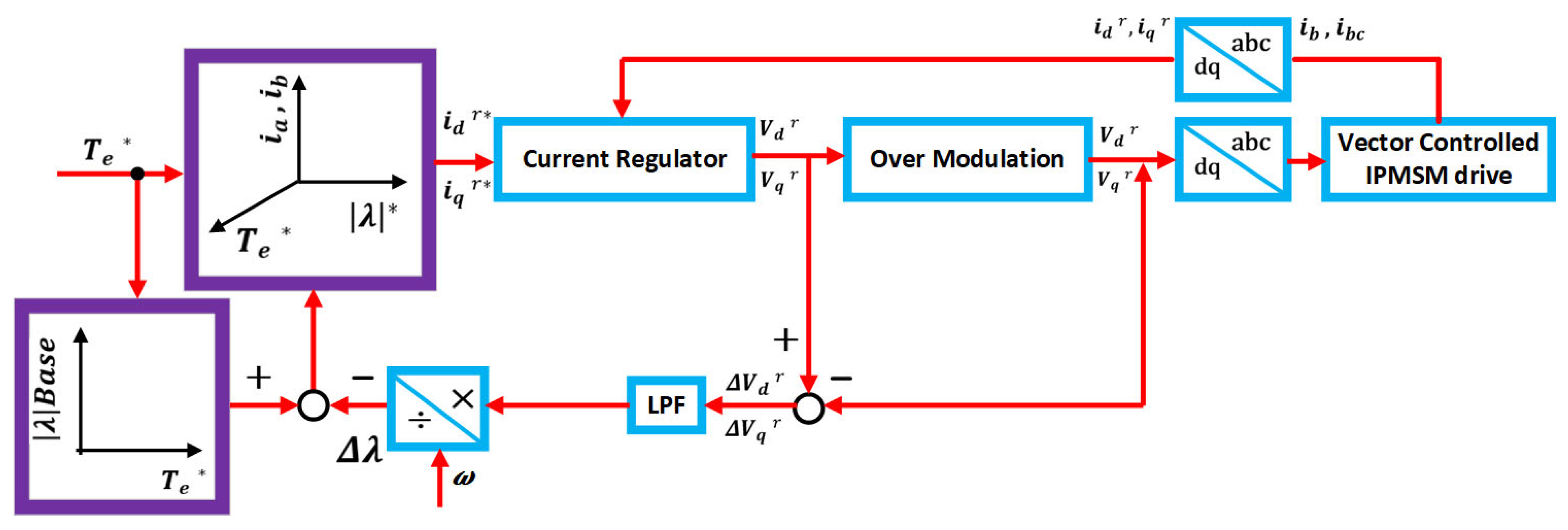
The primary FW control techniques covered in the literature are summarized in Table 2, along with a summary of their advantages and disadvantages. As can be observed, feedforward techniques (analytical, LUT-based) frequently have quick response times and are easy to implement in known scenarios, but they are sensitive to changes in parameters and necessitate a significant amount of offline effort. Although feedback techniques (such as SCR or voltage-regulating systems) are more resilient to parameter uncertainty, they may also cause complexity or stability problems.

5.6. Vector Current Control (VCC)

In this method, by varying the q-axis current, the d-axis current, or the current angle calculated in the MTPA region from the error of the voltage magnitude, we can achieve the transference over the base speed [84,85,87,90,92,117,118,119,120,121,122,123,124,125,126,127,128,129,130,131,132,133,134,135]; other authors consider that variations in the d, q currents or the current angle may be calculated from the duty cycles error as in [136,137,138]. Authors in other articles [139,140,141] claim that voltage error can also be a good source of the variation in d-q axis currents and angle for transition above the base speed in this strategy. Regulation using the voltage magnitude is the most famous strategy in many industrial applications. Usually, in this method, the feedback route of the voltage vector reading results is from the PID current controller’s output, and no voltage sensors are used at the output side of the power converter. Hence, this technique neglects many effects in the system, such as the signal delay and the power switch voltage drop [93,102].
In the case of regulating by utilizing duty cycle errors or voltage errors, these strategies depend on the power converter’s overmodulation capability and on allowing the maximum available voltage to be increased at extra current harmonics expenses. The voltage magnitude strategy is mainly based on a vector control feedback loop. This loop compares the voltage vector point generated by the PID controller within the voltage limit. If the standard value is higher than the enjoined limit, then the chosen variable of FW is tuned by the current vector controller to decrease the flux of the stator windings.
Moreover, in this method, the voltage controller can be combined using a closed-loop cascaded model of the FW bandwidth positioning and the current regulating relatively. Dynamic FW regulation is neglected when the case is an external speed control loop.
The voltage limit is the major drawback of this strategy. This voltage limit is defined as the partial amount of the maximum voltage that can be applied to the machine to sidestep the dynamics of the low current regulator and any possibility for unstable modes needed for disturbances with low frequency and load transients, so the critical point here is when starting the FW operation because this value impacts the powertrain power density. Furthermore, when using the Six-Step switching technique or working in the overmodulation zone, the DC voltage should be employed in these situations, which causes current harmonics, torque ripple, and control dynamics reduction, leading to vibrations and noise. Additionally, the nonlinear relationship between the magnitude of the voltage and the variable to control is another disadvantage of this strategy. It makes modifying the FW for a wide bandwidth of operating points challenging, and extra efforts are required for the same inputs because of the non-constant static gain of the closed-loop in all ranges of speed.
On the contrary, the main advantage of this method is that it considers the voltage drop of the resistor and the saturation effects in the transference from FW and LBEMF regions by knowing the exact amount of the parameters from the feedback path [87,134].
In [142], the authors study the effects of the error in the FW performance algorithm that may happen in the overmodulation between the applied voltage to the electric machine and the voltage vector on the feedback route. They also suggest a new strategy based on the minimization of the calculated voltage. At the same time, the control exists in the FW zone with minimum current. However, while applying this method, there is no consideration for resistor voltage drop and saturation effects, and it is only valid for SPMSMs. L. Sepulchre [93] developed a new FW algorithm that can work in the MPTV zone and smoothly transition between the FW and the LBEMF zones without switching techniques. The authors also claim that the power region is mainly affected by the battery’s maximum power, and they mentioned that experimental and simulation results are concordant. However, in the MTPV region, there are some differences in the d-q axis trajectories.
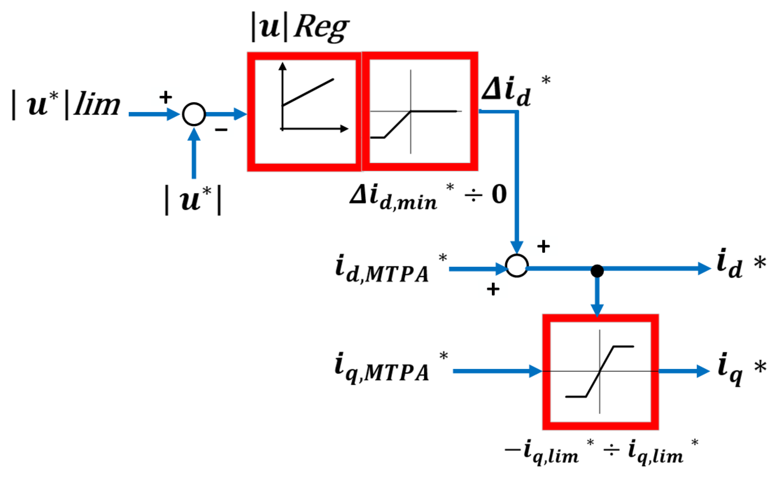
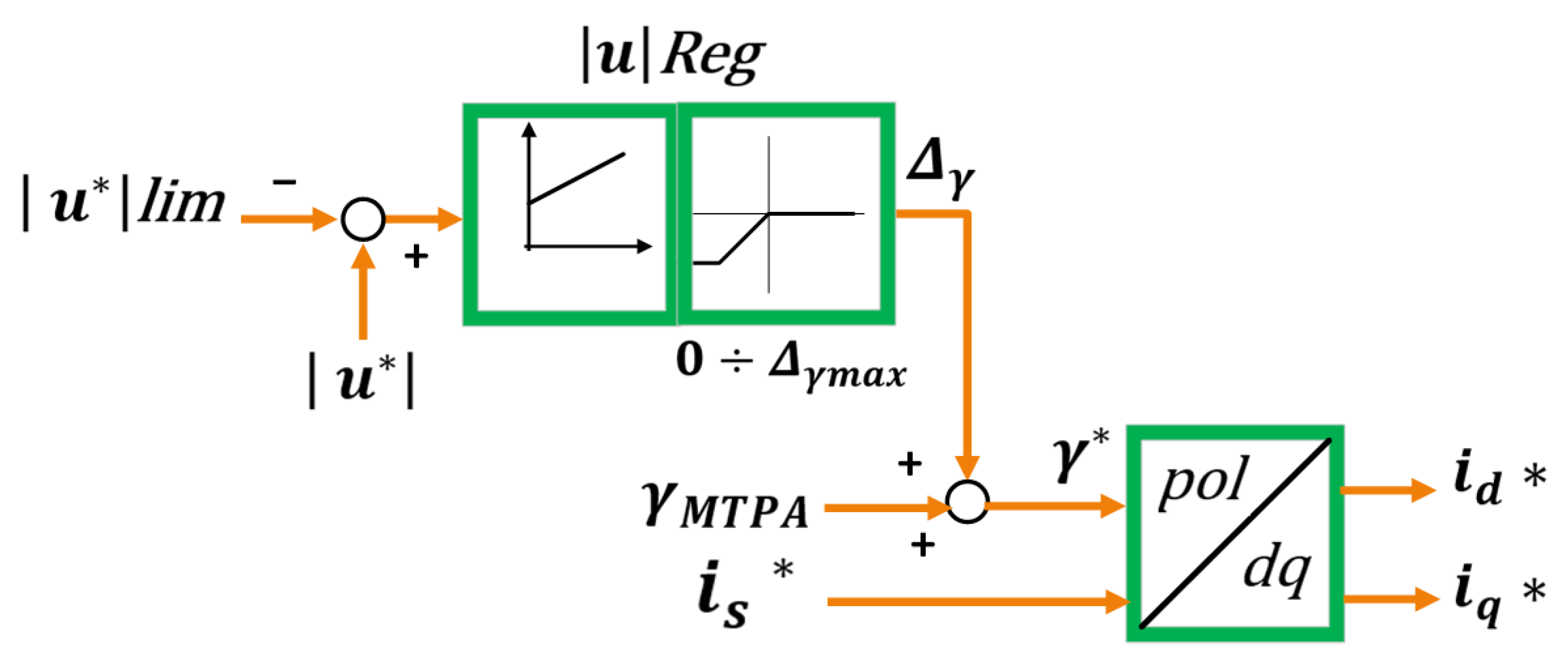
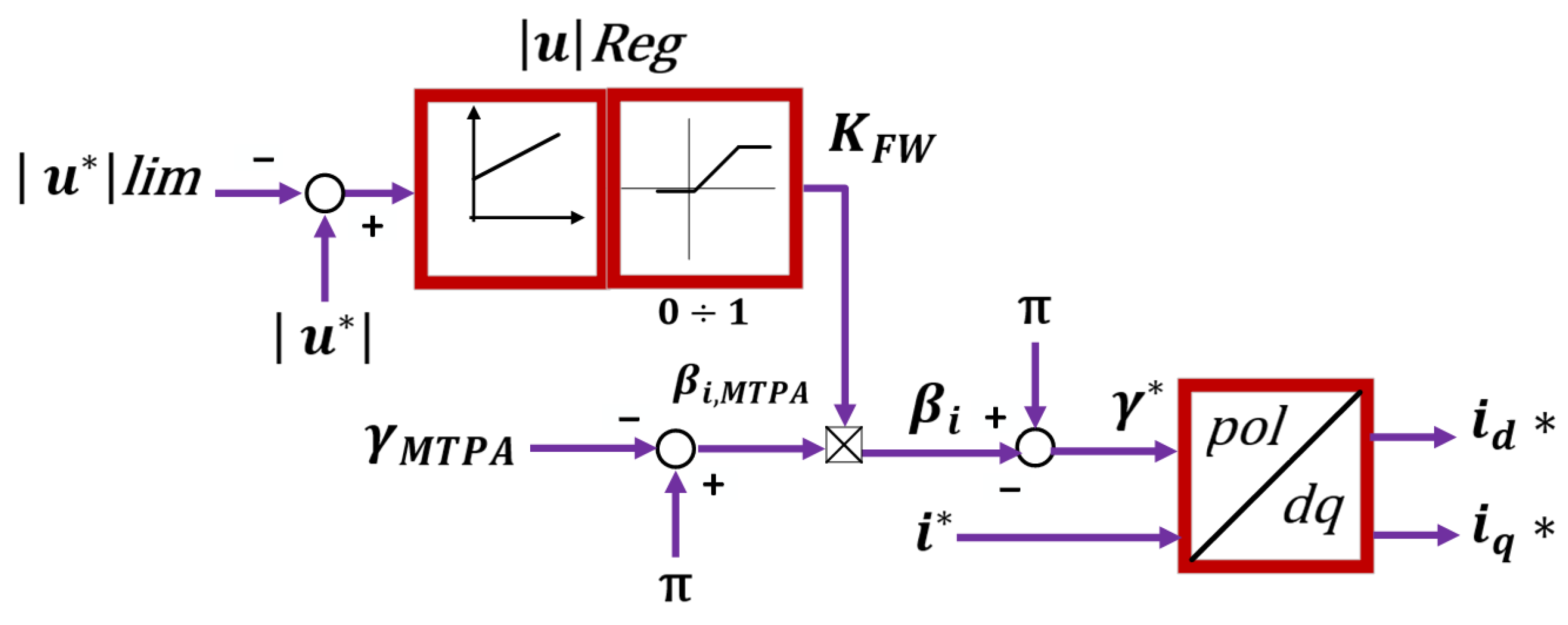
In [87], the authors suggest an adaptive gain voltage regulator. The suggestion is to have an extended speed range where the plant has a higher torque and is in stable mode versus the performance of the powertrain speed. Also, they created a static and dynamic analytical investigation of the feedback voltage control loop using the three different methods shown in Figure 24, Figure 25 and Figure 26 [87].
The features of VCC methods in IPMSM, SPMSM, and SyRM machines are described in Table 3, which compares a few implementations from the literature. These include the coordinate system (Cartesian d–q or polar), reference frame (real-valued or per-unit), and reference signal (speed or torque).
Many other categories and methods were discussed and developed by scientists in order to improve the precision of controlling the superior PMSM machine by considering various factors and viewpoints, as previewed below.
A hybrid approach of a combined flux-weakening velocity regulation of VCC and DFVC methods is suggested by scientists in [130] to exploit VCC and DFVC and overcome the drawbacks. When comparing the rated current with the intended current vector amplitude value, the proper PMSM velocity control mechanism was chosen. The VCC technique reduces over-current when accelerating with the rated current amplitude. The limit voltage condition is satisfied by the DFVC method when the current vector magnitude is less than its nominal value. Figure 27 shows the basic idea of the suggested switching regulation technique.
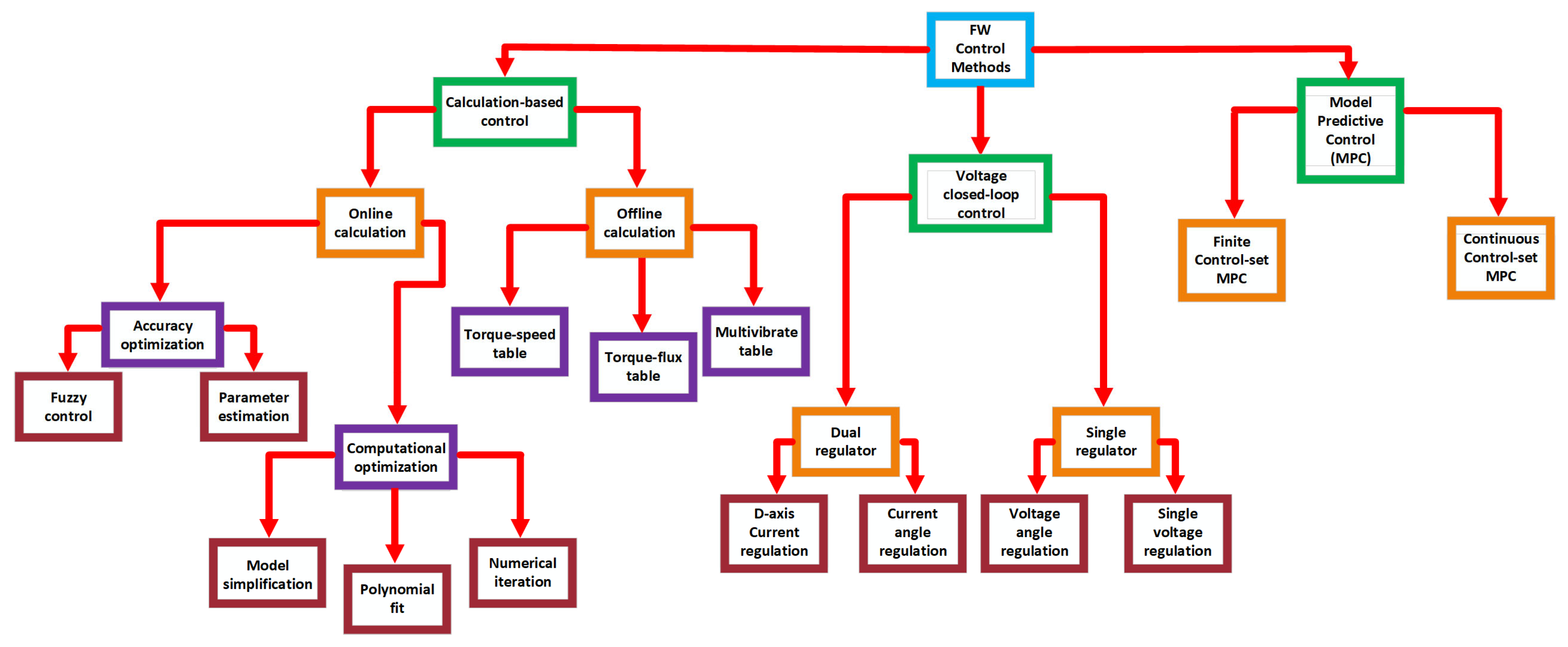
A different classification of the flux-weakening control theories leads to another division of FW control strategies, the calculation-based control methods, voltage closed-loop control methods, and model predictive control (MPC) methods, as appears in the diagram in Figure 28 [143].
Another way of grouping the flux-weakening control methods can be performed based on how to achieve the armature currents of the d-q axis categorized as feedforward, feedback, hybrid, and nonlinear control.
Feedforward solutions use control characteristics that have been analyzed analytically or experimentally. These characteristics are calculated to maximize motor performance within the presumptive feeding voltage and current limits. The demagnetizing d-axis current is derived from flux-weakening attributes as a function of operating speed. In contrast, the q-axis current command is derived from the torque command or the d-axis current [51,67,89,144,145,146,147,148]. In feedback approaches, the motor voltage and/or speed are measured, and the demagnetizing current (d-axis component) is adjusted to track the voltage limit at increasing speed. The demagnetizing current vector can be adjusted by monitoring the voltage or speed errors [149,150,151,152].
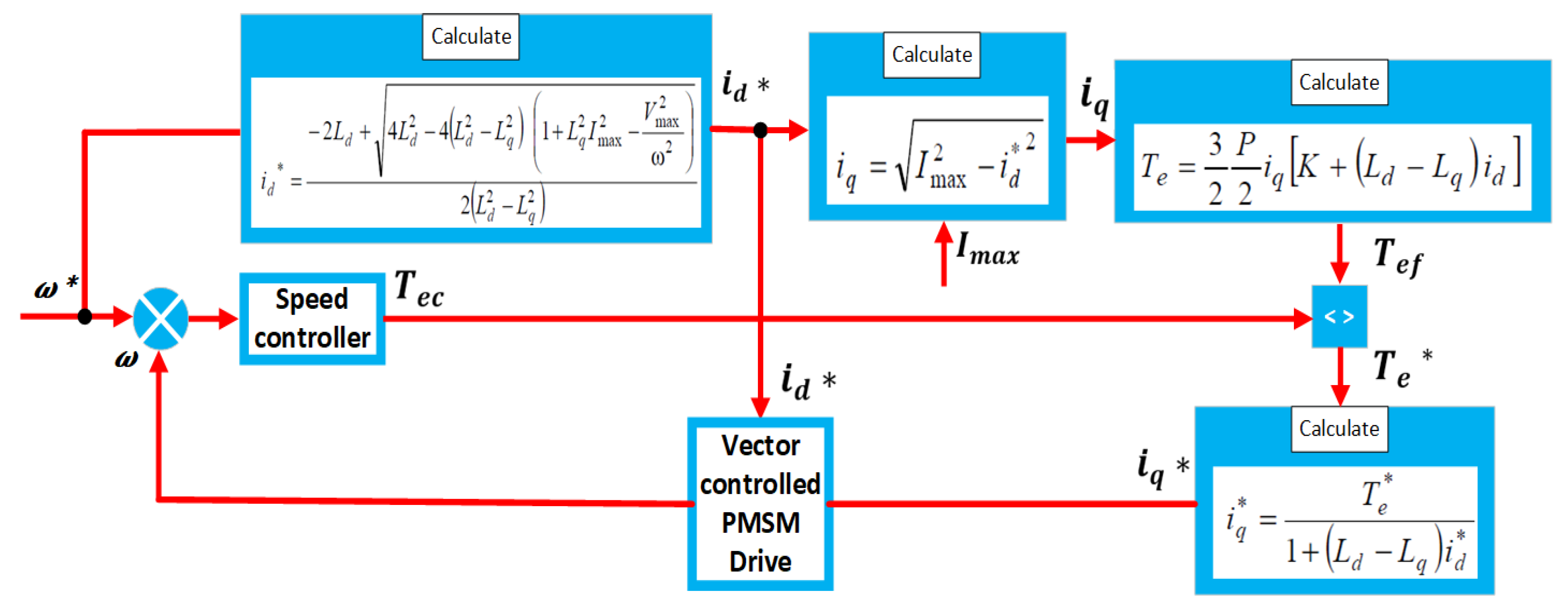
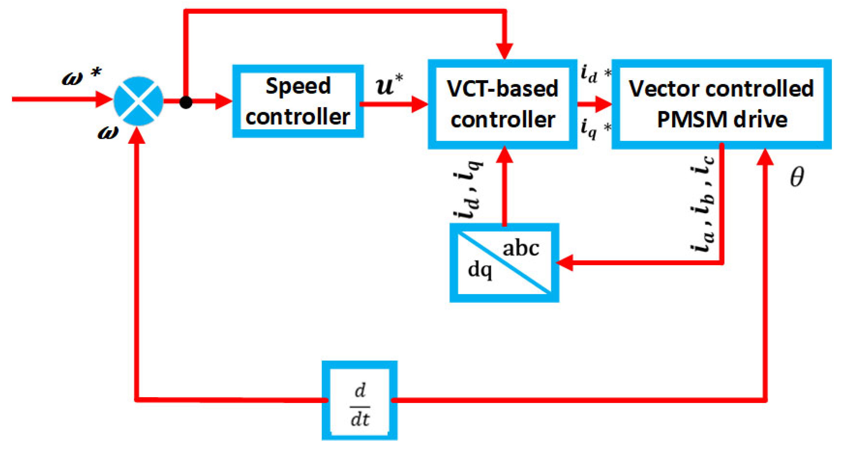
Additionally, hybrid approaches have been implemented to combine the benefits of feedforward and feedback systems. The optimization objectives modify the pre-calculated d-axis current command for Maximum Torque per Ampere (MTPA), whilst the torque command and d-axis current feedback decide the q-axis current command. The alternative method involves modifying the feedforward current references derived from MTPA using the feedback flux derived from the current controller’s integrator output [109,153,154,155,156]. Figure 29, Figure 30 and Figure 31 show the block diagrams of some of these techniques [82].

6. Discussion

EVs have rapidly entered the automotive sector, making it essential to develop efficiency, extend the range of driving for these vehicles, increase battery life, and obtain a robust, compact design. This paper focuses on how to obtain the maximum execution of the electric machine in all speed ranges through torque and speed control algorithms. Particular discussion is made on deep FW to achieve the maximum torque at high-speed ranges, which is needed for electric machines’ traction.
PMSM is one of the most popular electric machines used widely nowadays, especially in EVs and electric powertrains. IPMSMs are preferable in this domain, which is considered an outstanding candidate for vehicle propulsion due to many reasons and merits summarized as follows:
  • Light weight and compact size.
  • Low maintenance requirements.
  • Unique rotor structure that contributes to extra torque generation.
  • High torque and power density
  • Low torque ripple combined with high efficiency.
  • Precise speed control capability.
  • Effective performance at high-speed ranges.
  • Flux-weakening capability enabling extended constant-power operation.
There are significant variations between machine types in terms of flux-weakening performance. Because of their rotor saliency, which permits a considerable flux decrease with negative d-axis current and produces additional reluctance torque at high speeds, IPMSMs typically demonstrate higher FW capability. On the other hand, SPMSMs (which have surface-mounted magnets and almost nil saliency) have a smaller FW range and need higher demagnetizing currents to operate at high speeds. This increases the possibility of magnet demagnetization and usually limits the constant-power speed extension of these devices. Since they do not have permanent magnets, synchronous reluctance machines (SyRMs) naturally permit flux control by current. However, because of their reduced torque density, it can be difficult to achieve high torque at base speed. As a result, IPMSMs are typically preferred for deep FW applications that demand higher speeds. Since they do not have permanent magnets, synchronous reluctance machines (SyRMs) naturally permit flux control by current. However, because of their reduced torque density, it can be challenging to obtain high torque at base speed. IPMSMs are therefore typically preferred for deep FW applications that demand a more extended speed range. At the same time, SPMSMs and SyRMs might require more sophisticated control strategies or design concessions to achieve comparable high-speed performance. As explained in the last point above regarding the flux-weakening capability, it is a distinguishing factor that favors IPMSMs for deep FW applications.
Nevertheless, selecting the proper machine for such applications is a debatable topic. Thus, new topologies could be developed to meet these applications through suitable design and fabrication aligned with sustainability and life-cycle considerations within the suitable design and fabrication of our nature and life cycle. Primarily, we aim to reduce the use of rare materials and natural resources in electric machines. We are exploring new or advanced strategies that promise higher power density and efficiency at a lower expense than the machines currently in use, offering a hopeful outlook for the future of electric machine design.
PMSMs possess fundamental features, parameters, and characteristic curves. The power converter must achieve optimal efficiency in all speed ranges. Discussing varying characteristic parameters with current, voltage, and temperature limitations is a significant and urgent topic in the literature. Many authors have analyzed and studied the effects of the d-q axis inductance independent factor in PMSMs, which is related to the current limits, resistance, and flux linkage with temperature.
In this section, various FW control algorithms were extracted to obtain the maximum performance of the electric machine specifically for PMSMs. Table 4 below provides a concise comparison of the main FW control strategies reviewed. It highlights the approach of each method, and qualitatively indicates the speed range extension capability relative to its base speed. Table 5 clearly summarizes the main advantages and shortcomings of those FW control methods discussed in detail in the previous sub-sections. Vector Current Control (VCC), as presented and discussed in Section 5, is considered one of the most common selections for operating in the FW region.
Many authors suggest that transfer over the base speed can be achieved by varying the d-axis current, the q-axis current, or the current angle calculated in the MTPA region through some options such as the voltage magnitude, duty cycles error, or using the voltage error.
The authors in [122] propose to include experimental results and numerical simulations for varying d-q inductances related to the current of the d-q axis with 2D-LUTs in MTPA, MTPV, and torque equations. Furthermore, the authors suggest considering the voltage regulator output as the best settling for the VCC method, as the angle of current in the state of the d-axis or q-axis makes the controller dynamic performance at its maximum [87]. As a result, high efficiency and torque are achieved, and the power density increases, which is considered a lower voltage margin.
Moreover, the authors implemented an FW algorithm with speed limit and torque reference in a unified planner [85]. So, they implemented a low-cost microcontroller and an effective per-unit system executed at a low-level smooth transference from one trajectory to the other. The author’s article [90] classified some strategies that consider the deep FW operation from different methods that do not.
The literature related to the VCC method has tested diverse techniques for working in the FW zone. Table 6 compares the literature for some characteristics of the VCC strategy in IPMSM, SPMSM, and SyRM machines, such as the output voltage regulator (by q-axis variation, d-axis variation, or current angle variation), reference signal, reference system, coordinate system, and MPTV implementation.
Furthermore, Zhang et al.’s study [157] indicates that there are four primary approaches for PMSM velocity control in the FW region: Direct Flux Vector Control (DFVC), direct current calculation (DCC), Vector Current Control (VCC), and the LUT method. Ref. [158] provides some comparisons between various control techniques. Table 7 displays the comparison.
Finally, scientists in [143] examined the recent FW control strategies for PMSMs, classified them into three types according to control theories, enumerated the pros and cons of each FW strategy and its sub-technique, and contrasted these FW control methods based on their control, and computational performance as collected below in Table 8.
Practically speaking, the motor type, the needed performance, the available computing power, and the acceptable degree of complexity will all influence the choice of flux-weakening technique for a particular application. For example, a LUT-based or simple VCC technique might be selected if simplicity and stability are of the utmost importance. In contrast, a more intricate feedforward-plus-feedback or dual regulator strategy might be required to achieve the absolute maximum speed range. There is a noticeable trend toward more intelligent and adaptable FW techniques (such as fuzzy logic or machine-learning-tuned controllers) that can handle parameter fluctuations and provide stability as power electronics and processing capabilities continue to advance.
Table 4. Comparison of flux-weakening control methods for PMSMs in EVs.
Control MethodApproach and Key PrincipleSpeed Range Extension
Analytical Direct Calculation (solving equations FW)Solves simplified motor equations for id, iq setpoints (often neglecting saturation) to satisfy the voltage limitModerate—achieves FW by design, but accuracy depends on the model
Open-Loop Voltage Angle Control (Voltage-based FW)Controls the inverter voltage angle (d-axis voltage component) to weaken flux above base speed directly. Essentially, a feed-forward voltage control using the margin to the voltage limitModerate extending speed by utilizing available voltage headroom
Single Current Regulator (SCR) (single-loop FW)Uses one current regulator in the FW region instead of separate d/q regulators. At base speed, control switches from standard dual-loop (MTPA) to single-loop (FW) mode that directly controls d-axis current (with q-axis voltage held at limit)High—designed for deep FW operation, pushing to inverter voltage limit while maintaining stability
Unified Direct Flux Vector Control (UDFVC)Directly controls stator flux linkage via d-axis voltage and torque via q-axis current in the stator reference frame; manages load angle to stay within stability marginHigh capability of spanning full speed range, including deep FW, by adjusting flux and torque in coordination
Torque and Flux Control with LUT (Feed-forward and feedback)Combines a conventional closed-loop torque control (PI regulator for torque or speed) with feed-forward look-up tables that provide optimal id and iq setpoints for each operating condition (obtained via offline characterization)Very high achievement near optimal FW (approaches MTPV limit) as LUT can be populated with points that maximize speed for given torque
Vector Current Control (VCC) (Enhanced FOC for FW)Real-time adjusts the current vector (magnitude and angle) to meet torque demand while respecting the inverter voltage limit. Often implemented as an extension of FOC that gradually shifts the current angle as speed increases (includes variants like adaptive or voltage-angle-limited FOC)High—many automotive drives use this to transition into FW smoothly; fully utilizes DC bus in steady-state FW, though may not push as close to limits as LUT methods
Table 5. Comparison of FW control methods.
ReferencesControl MethodProsCons
[83,89,90,91,92,93]Analytical Direct Calculation Method
-
Good choice for high power motors with small stator resistance
-
Not working in MPTV, but flexible to be developed to work in it
-
Nice transient response
-
Stable transition between LBEMF and FW
-
Susceptible because it depends on machine’s parameter variations
-
Consuming additional time for d-q axis current calculation
-
Neglecting magnetic saturation effects
[98,99]Direct Open-loop Algorithm with Experimental LUT
-
No need to use mathematical equations
-
Depends on variable inductance because of the cross magnetization and magnetic saturation effects
-
Inverter follows the torque reference all the time without considering the magnetic saturation
-
Large experimental setup that needs sizeable memory storage
-
Consumes time with perilous test of the machine
[92,93,100,101,102]Single Current Regulator (SCR)
-
Absence of confliction between the d-q axis controlling current in the FW mode
-
Easy to reach saturation because the current controllers operate near the maximum voltage value.
-
Possibility of conflict in deep FW operation between the two current controllers and cause instability
-
Non-smooth analytical switching from low to high speeds (LBEMF to FW) and vice versa
-
Very sensitive stability to the current limit value and other parameters of controller
[53,93,103]Unified Direct Flux Vector Control (UDFVC)
-
Appropriate for many types of AC machines
-
Direct flux control by one regulation channel to the torque setpoints
-
Flux observer is required which mainly depends on the machine parameters
-
Not working in MPTV
-
Experimentally bench test-dependable method to find the maximum load torque
[104,105,106,107,108,109,110,111,112,113,114,115]Torque and Flux Control (TFC) Method with (LUTs)
-
Decreases the flux ripple and torque unlike as in the classic DTC strategy
-
Considers the effect of magnetic saturation
-
Large memory required for saving the 2D-LUTs and 1D-LUT for many results
-
Possibility for conflict of the controller in the FW when they operate at the same time.
-
Many offline measurements must be performed to fill in the tables
[84,87,90,92,117,118,119,120,121,122,123]Vector Current Control (VCC)
(Voltage magnitude)
-
Considering the voltage drop of the resistor and the saturation effects in the transference from FW and LBEMF regions
-
The limitation of maximum voltage that can applied
-
Neglect many effects in the system such as the signal delay and the power switches voltage drop because no usage of voltage sensors
-
Torque ripple and control dynamics reduction leads to vibrations and noise
-
Nonlinear relationship between the magnitude of the voltage and the variable to control makes it hard for modifying the FW for a wide bandwidth
[136,137,159]Vector Current Control (VCC)
(Duty cycle error)
-
Depends on the power converter overmodulation capability and on allowing the increase in the maximum
-
Extra current harmonics expenses
[139,140,141]Vector Current Control (VCC)
(Voltage error)
-
Depends on the power converter overmodulation capability and on allowing the increase in the maximum available voltage
-
Extra current harmonics expenses
Table 6. Comparison of machines using VCC strategy based on voltage magnitude.
Machine
Type
Reference
Signal
Reference SystemCoordinate
System
MTPV
Implementation
Voltage
Controller
Output
Transition to FWReferences
IPMSMSpeedRealCartesiand-axis currentContinuous[120]
IPMSMTorqueRealCartesiand-axis currentContinuous[93]
SyRMSpeedPer-unitPolarCurrent angleContinuous[134]
IPMSMSpeedRealCartesiand-axis currentContinuous[131]
IPMSMSpeedRealCartesiand-axis currentSwitched[121]
IPMSMTorqueRealPolarCurrent angleContinuous[125]
SPMSMSpeedRealCartesiandq-axis currentSwitched[123]
Table 7. Comparison of efficiency between FW methods.
ApproachVCCDCCDFVCLUT
ImplementationEasy to implementEasy to implementEasy to implementComplex
Stability in the FW regionPerformance varies across different operating regions due to controller parameter influenceMaintains stable operationMaintains stable operationEnsures stability even under strong magnetic saturation effects
Acceleration StateAutomatically manages transitions between MTPA and FW controlTransitioning between MTPA and FW is challenging when the operating point is always outside the current limit circleTransitioning between MTPA and FW is challenging when the operating point is always outside the current limit circle Roaming is very convenient based on the lookup table
Table 8. General comparison between different FW control theories.
MethodFeatureExecutionDrawbackReferences
LUT Methods
(Torque Speed)
Straightforward and simple table creationDirect look-up table (LUT)Fixed voltage boundaries[160,161,162,163,164,165,166]
LUT Methods
(Torque-Flux)
Extends the voltage limits without requiring new tablesCalculation of flux and LUTRequires indirect flux vector measurements[109,167,168]
LUT Methods
(Multivariate)
Offers precise results across varying motor parametersMultivariate LUT calculationsComplex and difficult table generation[169,170,171,172]
Online Calculation
(Model Simplification)
Produces exact solutions with minimal feedback informationDirect calculation of voltages from reference values Complex numerical operations[173,174,175,176,177,178]
Online Calculation
(Polynomial Fit)
Provides approximate solutions based on offline dataComputes FOC reference currents using polynomial fit iterative Relies on offline solution data as the currents of FW[179]
Online Calculation
(Numerical Iteration)
Delivers approximate solutions using an initial valueIterative computation of FOC reference currentsDependent on iteration cycles and convergence[97,180,181,182,183,184,185,186,187]
Online Calculation
(Parameter Estimation)
Enhances model precisionEstimates flux, resistance, and inductance onlineRequires precalculated offline parameter tables or signal injection[188,189,190,191,192,193,194]
Online Calculation
(Fuzzy Control)
Improves system resilience against mismatchesDynamically adjusts for model mismatch and errorsDepends on defined fuzzy logic rules[147,195,196]
Dual Regulator
(D-axis current regulation)
Dynamic adjustment of voltage boundaries Feedback based current reference adjustmentsDependent on motor characteristics [131,197,198,199]
Dual Regulator
(Anti-saturation Control)
Prevents excessive voltage during FW controlCorrects pre-limited voltagesLimited by saturation adjustments[139,151,200,201,202,203,204,205]
Dual Regulator
(Time Domain Optimization)
Optimized control using response timesAdjusts FW current based on time domain parametersPossible overshoots during current regulation[151,197,201,204,206,207]
Dual Regulator
(Tuning Frequency Domain)
Fine tuning for adaptive performanceRegulates control bandwidth for dynamic responseSlower response to time-based changes[117,202,203,208]
Dual Regulator
(Current Angle Regulation)
Boosts voltage gain by adaptive controlAdjusts voltage gainLimited by the adaptability of voltage gain[209]
Dual Regulator
(Frequency Feedback Control)
Guarantees system stability using feedback based on frequencyFeedback tuning based on frequency domain analysisDifficult implementation[87,209]

7. Conclusions

Because of their exceptional power, high efficiency, and wide speed range at constant power and torque density, PMSMs are preferred by EV manufacturers for these types of applications without relying on raw rare earth materials. In recent years, this has led to a surge in interest in the revolutionary development of new electric machines. In particular, IPMSMs are utilized in the market because of their greater torque and the additional power per volume that their mechanical construction allows them to obtain from the additional reluctant torque. A key component of electric machine control, the MTPA approach is frequently employed in propulsion implementations to attain peak performance in lower speed ranges. The FW approach controls the increased speed range and sustains maximum torque and steady power when the magnet is completely demagnetized; the MPTV method is required for high-speed ranges, necessitating the consideration of current limit references. The main features of control techniques in the FW domain are thoroughly reviewed in this work.
It includes detailed block diagrams and a thorough comparison of each strategy, providing a valuable resource for EV manufacturers, engineers, and researchers in electric machines and propulsion systems.
In this study, many findings related to the FW control methods for PMSM machines are presented. Feedforward FW methods enable broader constant-power operation and faster dynamics but demand accurate machine parameters and high computation. At the same time, feedback (VCC) strategies ensure robustness and stability with lower sensitivity to parameter errors. Efficiency, torque output, and smooth transitions between operating regions are all improved by hybrid techniques that incorporate LUTs or adaptive references. To improve EV range and battery life, future developments should consider system-level efficiency and integrate motor, power electronics, and energy source optimization. For seamless transitions from low-speed torque to high-speed power, unified firmware frameworks covering PMSMs and SynRMs are required throughout the entire speed–torque range. Lastly, sophisticated protection mechanisms are necessary to ensure reliability during fault conditions, protecting machines and converters from overvoltage, overcurrent, and other disruptions.
The most popular alternative, due to its easy-to-understand structure, is the VCC method, which also controls the coefficient of the applied voltage magnitude. This allows operation without relying on precise information about the machine’s specifications. The literature on the VCC of the FW zone of operation presents three different implementation types: (i) current along the d-axis, (ii) current along the q-axis, and (iii) current angle between the d-q axis. Although the current angle maximizes the voltage regulator output’s dynamic performance, a low voltage margin is recommended in this situation. This strategy may result in increased torque and economy.
It is essential to keep in mind that several challenges and suggestions for the future need to be considered and given careful thought. The flux-weakening research should prioritize robust, adaptive controllers that tolerate parameter variations through online estimation or uncertainty-resistant methods. Developing unified frameworks, such as MPC or AI-based controllers, can simplify structures while optimizing torque–flux allocation across the entire speed range. FW must also be integrated with other EV functions, including regenerative braking, sensorless operation, and thermal management, to ensure safe and high-speed performance. Exploration of new machine types (SynRM, PMa-SynRM, hybrid excited) will require tailored FW strategies, extending PMSM concepts while addressing unique characteristics. Ultimately, a standardized benchmarking framework is necessary to compare methods and identify best practices across studies consistently.
To sum up, the most recent FW control techniques for PMSMs in EVs have been compiled in this review, which also provides comparative analysis and helpful advice. To shed light on implementation trade-offs, we looked at strategy choices, machine topology influences, and quantitative performance metrics. Novel strategies were highlighted, such as integration with temperature restrictions, AI-based control, and sensorless operation. The study emphasizes the importance of combining contemporary control, power electronics, and machine design for dependable FW solutions. EV propulsion systems will become more intelligent, reliable, and efficient with further multidisciplinary study.

Author Contributions

Conceptualization, S.A. and M.A.; methodology, S.A., M.A. and H.C.; writing—original draft preparation, S.A. and M.A.; writing—review and editing, S.A., M.A. and H.C.; visualization, S.A., M.A. and H.C.; supervision, H.C.; project administration, M.A. and H.C. All authors have read and agreed to the published version of the manuscript.

Funding

This research received no external funding.

Data Availability Statement

No new data were created or analyzed in this study.

Conflicts of Interest

The authors declare no conflict of interest.

References

  1. Sivkov, O.; Novak, J. Flux weakening control of permanent magnet synchronous motor with losses reduction. In Proceedings of the 2021 XVIII International Scientific Technical Conference Alternating Current Electric Drives (ACED), Ekaterinburg, Russia, 24–27 May 2021. [Google Scholar] [CrossRef]
  2. Alwaqfi, S.M.N. Direct Voltage Control of an Interior Permanent Magnet Synchronous Motor in Overspeed Conditions. Master’s Thesis, Texas Tech University, Lubbock, TX, USA, 2024. [Google Scholar]
  3. Bilgin, B.; Magne, P.; Malysz, P.; Yang, Y.; Pantelic, V.; Preindl, M.; Korobkine, A.; Jiang, W.; Lawford, M.; Emadi, A. Making the case for electrified transportation. IEEE Trans. Transp. Electrif. 2015, 1, 4–17. [Google Scholar] [CrossRef]
  4. Finken, T.; Felden, M.; Hameyer, K. Comparison and design of different electrical machine types regarding their applicability in hybrid electrical vehicles. In Proceedings of the 2008 18th International Conference on Electrical Machines, Vilamoura, Portugal, 6–9 September 2008. [Google Scholar] [CrossRef]
  5. Karki, A.; Phuyal, S.; Tuladhar, D.; Basnet, S.; Shrestha, B.P. Status of Pure Electric Vehicle Power Train Technology and future prospects. Appl. Syst. Innov. 2020, 3, 35. [Google Scholar] [CrossRef]
  6. Abd Elhafez, A.A.; Aldalbehia, M.A.; Aldalbehia, N.F.; Alotaibi, F.R.; Alotaibia, N.A.; Alotaibi, R.S. Comparative Study for Machine Candidates for High Speed Traction Applications. Int. J. Electr. Eng. 2017, 10, 71–84. [Google Scholar]
  7. Cao, W.; Mecrow, B.C.; Atkinson, G.J.; Bennett, J.W.; Atkinson, D.J. Overview of Electric Motor Technologies Used for More Electric Aircraft (MEA). IEEE Trans. Ind. Electron. 2012, 59, 3523–3531. [Google Scholar] [CrossRef]
  8. Zeraoulia, M.; Benbouzid, M.E.H.; Diallo, D. Electric motor drive selection issues for hev propulsion systems: A comparative study. IEEE Trans. Veh. Technol. 2006, 55, 1756–1764. [Google Scholar] [CrossRef]
  9. Dorrel, D.; Knight, A.; Popescu, M.; Evans, L.; Staton, D. Comparison of different motor design drives for hybrid electric vehicles. In Proceedings of the 2010 IEEE Energy Conversion Congress and Exposition, Atlanta, GA, USA, 12–16 September 2010; pp. 3352–3359. [Google Scholar]
  10. Yang, Z.; Shang, F.; Brown, I.; Krishnamurthy, M. Comparative study of interior permanent magnet, induction, and switched reluctance motor drives for ev and hev applications. IEEE Trans. Transp. Electrif. 2015, 1, 245–254. [Google Scholar] [CrossRef]
  11. Zheng, P.; Wu, F.; Lei, Y.; Sui, Y.; Yu, B. Investigation of a novel 24-slot/14-pole sixphase fault-tolerant modular permanent-magnet in-wheel motor for electric vehicles. Energies 2013, 6, 4980–5002. [Google Scholar] [CrossRef]
  12. Wang, J.; Yuan, X.; Atallah, K. Design optimization of a surface-mounted permanentmagnet motor with concentrated windings for electric vehicle applications. IEEE Trans. Veh. Technol. 2013, 62, 1053–1064. [Google Scholar] [CrossRef]
  13. Fodorean, D.; Idoumghar, L.; Brevilliers, M.; Minciunescu, P.; Irima, C. Hybrid differential evolution algorithm employed for the optimum design of a high-speed PMSM used for ev propulsion. IEEE Trans. Ind. Electron. 2017, 64, 9824–9833. [Google Scholar] [CrossRef]
  14. Fodorean, D. Study of a high-speed motorization with improved performances dedicated for an electric vehicle. IEEE Trans. Magn. 2014, 50, 921–924. [Google Scholar] [CrossRef]
  15. Öksüztepe, E. In-Wheel Switched Reluctance Motor Design for Electric Vehicles by Using a Pareto-Based Multiobjective Differential Evolution Algorithm. IEEE Trans. Veh. Technol. 2017, 66, 4706–4715. [Google Scholar] [CrossRef]
  16. Bazzi, A.M. Electric machines and Energy Storage Technologies in evs and hevs for over a century. In Proceedings of the 2013 International Electric Machines & Drives Conference, Chicago, IL, USA, 12–15 May 2013. [Google Scholar] [CrossRef]
  17. Zhu, Z.Q.; Chu, W.Q.; Guan, Y. Quantitative comparison of electromagnetic performance of electrical machines for hevs/evs. CES Trans. Electr. Mach. Syst. 2017, 1, 37–47. [Google Scholar] [CrossRef]
  18. Riba, J.-R.; López-Torres, C.; Romeral, L.; Garcia, A. Rare-earth-free propulsion motors for Electric Vehicles: A technology review. Renew. Sustain. Energy Rev. 2016, 57, 367–379. [Google Scholar] [CrossRef]
  19. Finken, T.; Hombitzer, M.; Hameyer, K. Study and comparison of several permanent-magnet excited rotor types regarding their applicability in electric vehicles. In Proceedings of the 2010 Emobility—Electrical Power Train, Leipzig, Germany, 8–9 November 2010. [Google Scholar] [CrossRef]
  20. Boldea, I.; Tutelea, L.N.; Parsa, L.; Dorrell, D. Automotive electric propulsion systems with reduced or no permanent magnets: An overview. IEEE Trans. Ind. Electron. 2014, 61, 5696–5711. [Google Scholar] [CrossRef]
  21. Burwell, M.; Goss, J.; Popescu, M. Performance/cost comparison of induction-motor & permanent-magnet-motor in a hybrid electric car. Int. Copp. Assoc. 2013. [Google Scholar]
  22. Soderžnik, M.; Rožman, K.Ž.; Kobe, S.; McGuiness, P. The grain-boundary diffusion process in Nd–Fe–B sintered magnets based on the electrophoretic deposition of DYF3. Intermetallics 2012, 23, 158–162. [Google Scholar] [CrossRef]
  23. Thomson, M.M.; Nietfeld, J.L. Knowledge, monitoring, and beliefs: A comparative analysis among preservice teachers from three different stem-focused programs. J. Interdiscip. Teach. Leadersh. 2017, 1, 19–27. [Google Scholar] [CrossRef]
  24. Jahns, T. Getting rare-earth magnets out of EV traction machines: A review of the many approaches being pursued to minimize or eliminate rare-earth magnets from future EV drivetrains. IEEE Electrif. Mag. 2017, 5, 6–18. [Google Scholar] [CrossRef]
  25. Guan, Y.; Zhu, Z.Q.; Afinowi, I.A.A.; Mipo, J.C.; Farah, P. Difference in maximum torque-speed characteristics of induction machine between motor and Generator Operation Modes for Electric Vehicle Application. Electr. Power Syst. Res. 2016, 136, 406–414. [Google Scholar] [CrossRef]
  26. Sira-Ramirez, H.; Gonzalez-Montanez, F.; Cortes-Romero, J.A.; Luviano-Juarez, A. A robust linear field-oriented voltage control for the induction motor: Experimental results. IEEE Trans. Ind. Electron. 2013, 60, 3025–3033. [Google Scholar] [CrossRef]
  27. Bozhko, S.; Dymko, S.; Kovbasa, S.; Peresada, S.M. Maximum torque-per-AMP control for traction IM drives: Theory and experimental results. IEEE Trans. Ind. Appl. 2017, 53, 181–193. [Google Scholar] [CrossRef]
  28. Chau, K.T.; Li, W. Overview of electric machines for electric and hybrid vehicles. Int. J. Veh. Des. 2014, 64, 46. [Google Scholar] [CrossRef]
  29. Chinmaya, K.A.; Singh, G.K. Integrated onboard single-stage battery charger for pevs incorporating asymmetrical six-phase Induction Machine. IET Electr. Syst. Transp. 2019, 9, 8–15. [Google Scholar] [CrossRef]
  30. Morimoto, S.; Ooi, S.; Inoue, Y.; Sanada, M. Experimental evaluation of a rare-earth-free pmasynrm with ferrite magnets for automotive applications. IEEE Trans. Ind. Electron. 2014, 61, 5749–5756. [Google Scholar] [CrossRef]
  31. Bianchi, N.; Mahmoud, H. An analytical approach to design the PM IN PMAREL motors robust toward the demagnetization. IEEE Trans. Energy Convers. 2016, 31, 800–809. [Google Scholar] [CrossRef]
  32. Bianchi, N.; Bolognani, S.; Carraro, E.; Castiello, M.; Fornasiero, E. Electric vehicle traction based on synchronous reluctance motors. IEEE Trans. Ind. Appl. 2016, 52, 4762–4769. [Google Scholar] [CrossRef]
  33. Reddy, P.B.; Grace, K.; El-Refaie, A. Conceptual design of sleeve rotor synchronous reluctance motor for traction applications. IET Electr. Power Appl. 2016, 10, 368–374. [Google Scholar] [CrossRef]
  34. Trancho, E.; Ibarra, E.; Arias, A.; Kortabarria, I.; Prieto, P.; de Alegría, I.M.; Andreu, J.; López, I. Sensorless Control Strategy for light-duty EVS and efficiency loss evaluation of high frequency injection under standardized urban driving cycles. Appl. Energy 2018, 224, 647–658. [Google Scholar] [CrossRef]
  35. Ding, W.; Yang, S.; Hu, Y.; Li, S.; Wang, T.; Yin, Z. Design consideration and evaluation of a 12/8 high-torque modular-stator hybrid excitation switched reluctance machine for EV applications. IEEE Trans. Ind. Electron. 2017, 64, 9221–9232. [Google Scholar] [CrossRef]
  36. Afjei, E.; Toliyat, H.A. A novel multilayer switched reluctance motor. IEEE Power Eng. Rev. 2002, 22, 73. [Google Scholar] [CrossRef]
  37. Desai, P.C.; Krishnamurthy, M.; Schofield, N.; Emadi, A. Novel switched reluctance machine configuration with higher number of rotor poles than stator poles: Concept to implementation. IEEE Trans. Ind. Electron. 2010, 57, 649–659. [Google Scholar] [CrossRef]
  38. Cheewoo, L.; Krishnan, R. New designs of a two-phase e-core switched reluctance machine by optimizing the magnetic structure for a specific application: Concept, design, and analysis. IEEE Trans. Ind. Appl. 2009, 45, 1804–1814. [Google Scholar] [CrossRef]
  39. Nguyen, D.-M.; Bahri, I.; Krebs, G.; Berthelot, E.; Marchand, C.; Ralev, I.; Burkhart, B.; De Doncker, R.W. Efficiency improvement by the intermittent control for switched reluctance machine in automotive application. IEEE Trans. Ind. Appl. 2019, 55, 4167–4182. [Google Scholar] [CrossRef]
  40. Ooi, S.; Morimoto, S.; Sanada, M.; Inoue, Y. Performance Evaluation of a High-Power-Density PMASynRM With Ferrite Magnets. IEEE Trans. Ind. Appl. 2013, 49, 1308–1315. [Google Scholar] [CrossRef]
  41. Vagati, A.; Boazzo, B.; Guglielmi, P.; Pellegrino, G. Ferrite assisted synchronous reluctance machines: A general approach. In Proceedings of the 2012 20th International Conference on Electrical Machines, Marseille, France, 2–5 September 2012; pp. 1315–1321. [Google Scholar] [CrossRef]
  42. Krishnan, R. Permanent Magnet Synchronous and Brushless DC Motor Drives; CRC Press: Boca Raton, FL, USA, 2010; pp. 34–42. [Google Scholar]
  43. Idoko, H.C.; Akuru, U.B.; Wang, R.; Popoola, O. Potentials of Brushless Stator-Mounted Machines in Electric Vehicle Drives—A Literature Review. World Electr. Veh. J. 2022, 13, 93. [Google Scholar] [CrossRef]
  44. Hedon, M. Modeling and Simulation of a Hybrid Powertrain. Master’s Thesis, KTH Royal Institute of Technology, Stockholm, Sweden, 2018; pp. 29–34. Available online: https://kth.diva-portal.org/smash/get/diva2:1249494/FULLTEXT01.pdf (accessed on 3 June 2023).
  45. Fresneau, D. Increasing the Range of EV with the Same Battery—Part II—More Efficiency with Better Software, Silicon Mobility. 2019. Available online: https://www.silicon-mobility.com/increasing-the-range-of-ev-with-the-same-battery-part-ii-more-efficiency-with-better-software/ (accessed on 4 June 2023).
  46. Park, J.-H.; Jo, W.; Jeon, E.-T.; Kim, S.-H.; Lee, C.-H.; Lee, J.-H.; Lee, J.-H.; Yi, J.; Won, C.-Y. Variable Switching Frequency Control-Based Six-Step Operation Method of a Traction Inverter for Driving an Interior Permanent Magnet Synchronous Motor for a Railroad Car. IEEE Access 2022, 10, 33829–33843. [Google Scholar] [CrossRef]
  47. Gerada, D.; Mebarki, A.; Brown, N.L.; Gerada, C.; Cavagnino, A.; Boglietti, A. High-Speed Electrical Machines: Technologies, Trends, and Developments. IEEE Trans. Ind. Electron. 2014, 61, 2946–2959. [Google Scholar] [CrossRef]
  48. Chedot, L.; Friedrich, G. A cross saturation model for interior permanent magnet synchronous machine. Application to a starter-generator. In Proceedings of the Conference Record of the 2004 IEEE Industry Applications Conference, 2004. 39th IAS Annual Meeting, Seattle, WA, USA, 3–7 October 2004; p. 70. [Google Scholar] [CrossRef]
  49. Tan, L.N.; Pham, T.C. Optimal Tracking Control for PMSM With Partially Unknown Dynamics, Saturation Voltages, Torque, and Voltage Disturbances. IEEE Trans. Ind. Electron. 2022, 69, 3481–3491. [Google Scholar] [CrossRef]
  50. Bose, B.K. Variable Frequency Permanent Magnet AC Machine Drives. In Power Electronics and Variable Frequency Drives: Technology and Applications; IEEE: Piscataway, NJ, USA, 1997; pp. 277–331. [Google Scholar] [CrossRef]
  51. Taghavi, S.M.; Jain, M.; Williamson, S.S. A comparative study of sensorless control techniques of interior permanent magnet synchronous motor drives for electric vehicles. In Proceedings of the 2011 IEEE Vehicle Power and Propulsion Conference, Chicago, IL, USA, 6–9 September 2011; pp. 1–7. [Google Scholar] [CrossRef]
  52. Pellegrino, G.; Armando, E.; Guglielmi, P. Direct Flux Field-Oriented Control of IPM Drives with Variable DC Link in the Field-Weakening Region. IEEE Trans. Ind. Appl. 2009, 45, 1619–1627. [Google Scholar] [CrossRef]
  53. Pellegrino, G.; Bojoi, R.I.; Guglielmi, P. Unified Direct-Flux Vector Control for AC Motor Drives. IEEE Trans. Ind. Appl. 2011, 47, 2093–2102. [Google Scholar] [CrossRef]
  54. Jung, S.-Y.; Hong, J.; Nam, K. Current Minimizing Torque Control of the IPMSM Using Ferrari’s Method. IEEE Trans. Power Electron. 2013, 28, 5603–5617. [Google Scholar] [CrossRef]
  55. Ohnuma, T. Current control of PMSM based on maximum torque control reference frame. In Proceedings of the AIP Conference Proceedings, Penang, Malaysia, 27–29 January 2016. [Google Scholar] [CrossRef]
  56. Nakashima, S.; Inagaki, Y.; Miki, I. Sensorless initial rotor position estimation of surface permanent-magnet synchronous motor. IEEE Trans. Ind. Appl. 2000, 36, 1598–1603. [Google Scholar] [CrossRef]
  57. Field-Weakening Control (with MTPA) of PMSM (No Date) Field-Weakening Control (with MTPA) of PMSM—MATLAB & Simulink Example. Available online: https://www.mathworks.com/help/mcb/gs/field-weakening-control-mtpa-pmsm.html#d124e5944 (accessed on 11 June 2023).
  58. Alzayed, M.; Chaoui, H. Efficient Simplified Current Sensorless Dynamic Direct Voltage MTPA of Interior PMSM for Electric Vehicles Operation. IEEE Trans. Veh. Technol. 2022, 71, 12701–12710. [Google Scholar] [CrossRef]
  59. Shakib, S.M.S.I.; Xiao, D.; Dutta, R.; Alam, K.S.; Osman, I.; Rahman, M.F.; Akter, P. An Analytical Approach to Direct Torque and Flux Control of Interior Permanent Magnet Synchronous Machine for Deep Field Weakening Without Using Pre-calculated Lookup Tables. In Proceedings of the 2019 10th International Conference on Power Electronics and ECCE Asia (ICPE 2019—ECCE Asia), Busan, Republic of Korea, 27–30 May 2019; pp. 3196–3202. [Google Scholar] [CrossRef]
  60. Meyer, M.; Grote, T.; Bocker, J. Direct torque control for interior permanent magnet synchronous motors with respect to optimal efficiency. In Proceedings of the 2007 European Conference on Power Electronics and Applications, Aalborg, Denmark, 2–5 September 2007; pp. 1–9. [Google Scholar] [CrossRef]
  61. Inoue, Y.; Morimoto, S.; Sanada, M. Comparative Study of PMSM Drive Systems Based on Current Control and Direct Torque Control in Flux-Weakening Control Region. IEEE Trans. Ind. Appl. 2012, 48, 2382–2389. [Google Scholar] [CrossRef]
  62. Dwivedi, S.; Singh, B. Vector Control vs Direct Torque Control comparative evaluation for PMSM drive. In Proceedings of the 2010 Joint International Conference on Power Electronics, Drives and Energy Systems & 2010 Power India, New Delhi, India, 20–23 December 2010; pp. 1–8. [Google Scholar] [CrossRef]
  63. Montalvo-Ortiz, E.E.; Foster, S.N.; Cintron-Rivera, J.G.; Strangas, E.G. Comparison between a spoke-type PMSM and a PMASynRM using ferrite magnets. In Proceedings of the 2013 International Electric Machines & Drives Conference, Chicago, IL, USA, 12–15 May 2013; pp. 1080–1087. [Google Scholar] [CrossRef]
  64. Tinazzi, F.; Sandulescu, P.; Peretti, L.; Zigliotto, M. On the true maximum efficiency operations of synchronous motor drives. In Proceedings of the 2017 IEEE 12th International Conference on Power Electronics and Drive Systems (PEDS), Honolulu, HI, USA, 12–15 December 2017; pp. 1043–1048. [Google Scholar] [CrossRef]
  65. Hackl, C.M.; Kullick, J.; Eldeeb, H.; Horlbeck, L. Analytical computation of the optimal reference currents for MTPC/MTPA, MTPV and MTPF operation of anisotropic synchronous machines considering stator resistance and mutual inductance. In Proceedings of the 2017 19th European Conference on Power Electronics and Applications (EPE’17 ECCE Europe), Warsaw, Poland, 11–14 September 2017; pp. P.1–P.10. [Google Scholar] [CrossRef]
  66. Rahman, M.A.; Zhou, P. Analysis of brushless permanent magnet synchronous motors. IEEE Trans. Ind. Electron. 1996, 43, 256–267. [Google Scholar] [CrossRef]
  67. Jahns, T.M.; Kliman, G.B.; Neumann, T.W. Interior Permanent-magnet synchronous motors for adjustable-speed drives. IEEE Trans. Ind. Appl. 1986, IA-22, 738–747. [Google Scholar] [CrossRef]
  68. Pillay, P.; Krishnan, R. Application characteristics of permanent magnet synchronous and brushless DC motors for servo drives. IEEE Trans. Ind. Appl. 1991, 27, 986–996. [Google Scholar] [CrossRef]
  69. Chaoui, H.; Khayamy, M.; Okoye, O. MTPA based Operation Point Speed tracking for PMSM drives without explicit current regulation. Electr. Power Syst. Res. 2017, 151, 125–135. [Google Scholar] [CrossRef]
  70. Samala, Naga Santhoshi. Cogging Torque and Torque Ripple Analysis on Permanent Magnet Synchronous Machines. 2019. Available online: https://www.politesi.polimi.it/handle/10589/148988 (accessed on 14 October 2024).
  71. Pellegrino, G.; Armando, E.; Guglielmi, P. Direct-Flux Vector Control of IPM Motor Drives in the Maximum Torque Per Voltage Speed Range. IEEE Trans. Ind. Electron. 2012, 59, 3780–3788. [Google Scholar] [CrossRef]
  72. Kim, S.-H.; Sul, S.-K. Voltage control strategy for maximum torque operation of an induction machine in the field-weakening region. IEEE Trans. Ind. Electron. 1997, 44, 512–518. [Google Scholar] [CrossRef]
  73. Bae, B.-H.; Patel, N.; Schulz, S.; Sul, S.-K. New field weakening technique for high saliency interior permanent magnet motor. In Proceedings of the 38th IAS Annual Meeting on Conference Record of the Industry Applications Conference, 2003, Salt Lake City, UT, USA, 12–16 October 2003; Volume 2, pp. 898–905. [Google Scholar] [CrossRef]
  74. Lubin, T.; Razik, H.; Rezzoug, A. Magnetic saturation effects on the control of a synchronous reluctance machine. IEEE Trans. Energy Convers. 2002, 17, 356–362. [Google Scholar] [CrossRef]
  75. Guha, S.; Kar, N.C. A New Method of Modeling Magnetic Saturation in Electrical Machines. In Proceedings of the 2006 Canadian Conference on Electrical and Computer Engineering, Ottawa, ON, Canada, 7–10 May 2006; pp. 1094–1097. [Google Scholar] [CrossRef]
  76. Chen, H.; Chen, Y.; Huang, S.-R.; Zhang, F. Calculation of inductance of permanent magnet synchronous motor considering permanent magnet flux linkage variation of load conditions. In Proceedings of the 2014 IEEE Conference and Expo Transportation Electrification Asia-Pacific (ITEC Asia-Pacific), Beijing, China, 31 August–3 September 2014; pp. 1–6. [Google Scholar] [CrossRef]
  77. Aoyama, M.; Noguchi, T. Flux Intensifying PM-Motor with Variable Leakage Magnetic Flux Technique. In Proceedings of the 2018 International Power Electronics Conference (IPEC-Niigata 2018-ECCE Asia), Niigata, Japan, 20–24 May 2018; pp. 718–725. [Google Scholar] [CrossRef]
  78. Soong, W.L. Design and Modelling of Axially Laminated Interior Permanent Magnet Motor Drives for Field-Weakening Applications. Ph.D. Thesis, University of Glasgow, Scotland, UK, 1993. [Google Scholar]
  79. Morimoto, S.; Takeda, Y.; Hirasa, T.; Taniguchi, K. Expansion of operating limits for permanent magnet motor by current vector control considering inverter capacity. IEEE Trans. Ind. Appl. 1990, 26, 866–871. [Google Scholar] [CrossRef]
  80. Song, T.; Zhang, Z.; Liu, H.; Hu, W. Multi-objective optimisation design and performance comparison of permanent magnet synchronous motor for EVS based on FEA. IET Electr. Power Appl. 2019, 13, 1157–1166. [Google Scholar] [CrossRef]
  81. Jia, L.; Qin, Y.; Liang, J.; Liu, Z.; Diao, L.; An, M. (Eds.) Proceedings of the 5th International Conference on Electrical Engineering and Information Technologies for Rail Transportation (EITRT) 2021; Lecture Notes in Electrical Engineering; Springer Nature: London, UK, 2022. [Google Scholar] [CrossRef]
  82. Lu, D.; Kar, N.C. A review of flux-weakening control in permanent magnet synchronous machines. In Proceedings of the 2010 IEEE Vehicle Power and Propulsion Conference, Lille, France, 1–3 September 2010; pp. 1–6. [Google Scholar] [CrossRef]
  83. Morimoto, S.; Sanada, M.; Takeda, Y. Wide-speed operation of interior permanent magnet synchronous motors with high-performance current regulator. IEEE Trans. Ind. Appl. 1994, 30, 920–926. [Google Scholar] [CrossRef]
  84. Kim, J.-M.; Sul, S.-K. Speed control of interior permanent magnet synchronous motor drive for the flux weakening operation. IEEE Trans. Ind. Appl. 1997, 33, 43–48. [Google Scholar] [CrossRef]
  85. Miguel-Espinar, C.; Heredero-Peris, D.; Gross, G. Llonch-Masachs and D. Montesinos-Miracle. Maximum Torque per Voltage Flux-Weakening Strategy with Speed Limiter for PMSM Drives. IEEE Trans. Ind. Electron. 2021, 68, 9254–9264. [Google Scholar] [CrossRef]
  86. Command Modes (No Date) FluxMotor Doc. Available online: https://fluxmotordoc.altair.com/helponlines/helponline/292 (accessed on 13 July 2023).
  87. Bolognani, S.; Calligaro, S.; Petrella, R. Adaptive Flux-Weakening Controller for Interior Permanent Magnet Synchronous Motor Drives. IEEE J. Emerg. Sel. Top. Power Electron. 2014, 2, 236–248. [Google Scholar] [CrossRef]
  88. Wang, J.; Wu, J.; Gan, C.; Sun, Q. Comparative study of flux-weakening control methods for PMSM drive over wide speed range. In Proceedings of the 2016 19th International Conference on Electrical Machines and Systems (ICEMS), Chiba, Japan, 13–16 November 2016; pp. 1–6. [Google Scholar]
  89. Tursini, M.; Chiricozzi, E.; Petrella, R. Feedforward Flux-Weakening Control of Surface-Mounted Permanent-Magnet Synchronous Motors Accounting for Resistive Voltage Drop. IEEE Trans. Ind. Electron. 2010, 57, 440–448. [Google Scholar] [CrossRef]
  90. Sepulchre, L.; Fadel, M.; Pietrzak-David, M.; Porte, G. Flux-weakening strategy for high speed PMSM for vehicle application. In Proceedings of the 2016 International Conference on Electrical Systems for Aircraft, Railway, Ship Propulsion and Road Vehicles & International Transportation Electrification Conference (ESARS-ITEC), Toulouse, France, 2–4 November 2016; pp. 1–7. [Google Scholar] [CrossRef]
  91. Fangyang, Z.; Feng, R.; Jianjun, L.; Peng, H. Study on Flux-Weakening Control for PMSM. In Proceedings of the 2011 Fourth International Symposium on Knowledge Acquisition and Modeling, Sanya, China, 8–9 October 2011; pp. 192–195. [Google Scholar] [CrossRef]
  92. Gao, F.; Bozhko, S.; Shen, Y.S.; Asher, G. Control design for PMM starter-generator operated in flux-weakening mode. In Proceedings of the 2013 48th International Universities’ Power Engineering Conference (UPEC), Dublin, Ireland, 2–5 September 2013; pp. 1–6. [Google Scholar] [CrossRef]
  93. Sepulchre, L.; Fadel, M.; Pietrzak-David, M.; Porte, G. MTPV Flux-Weakening Strategy for PMSM High Speed Drive. IEEE Trans. Ind. Appl. 2018, 54, 6081–6089. [Google Scholar] [CrossRef]
  94. Sanz, A.; Oyarbide, E.; Gálvez, R.; Bernal, C.; Molina, P.; Vicente, I.S. Analytical maximum torque per volt control strategy of an interior permanent magnet synchronous motor with very low battery voltage. IET Electr. Power Appl. 2019, 13, 1042–1050. [Google Scholar] [CrossRef]
  95. Shi, Y.F.; Zhu, Z.Q.; Chen, Y.S.; Howe, D. Influence of winding resistance on flux-weakening performance of a permanent magnet brushless AC drive. In Proceedings of the 2002 International Conference on Power Electronics, Machines and Drives (Conf. Publ. No. 487), Sante Fe, NM, USA, 16–18 April 2002; pp. 392–397. [Google Scholar] [CrossRef]
  96. Olarescu, N.V.; Weinmann, M.; Zeh, S.; Musuroi, S. Novel flux weakening control algorithm for PMSMS. In Proceedings of the 2009 International Conference on Power Engineering, Energy and Electrical Drives, Lisbon, Portugal, 18–20 March 2009; pp. 123–127. [Google Scholar] [CrossRef]
  97. Wang, S.; Kang, J.; Degano, M.; Galassini, A.; Gerada, C. An Accurate Wide-Speed Range Control Method of IPMSM Considering Resistive Voltage Drop and Magnetic Saturation. IEEE Trans. Ind. Electron. 2020, 67, 2630–2641. [Google Scholar] [CrossRef]
  98. Meyer, M.; Bocker, J. Optimum Control for Interior Permanent Magnet Synchronous Motors (IPMSM) in Constant Torque and Flux Weakening Range. In Proceedings of the 2006 12th International Power Electronics and Motion Control Conference, Portoroz, Slovenia, 30 August–1 September 2006; pp. 282–286. [Google Scholar] [CrossRef]
  99. Kunter, M.S.; Schoenen, T.; Hoffmann, W.; De Doncker, R.W. IPMSM control regime for a hybrid-electric vehicle application. In Proceedings of the 2010 Emobility—Electrical Power Train, Leipzig, Germany, 8–9 November 2010; pp. 1–5. [Google Scholar] [CrossRef]
  100. Xu, L.; Zhang, Y.; Guven, M.K. A new method to optimize q-axis voltage for deep flux weakening control of IPM machines based on single current regulator. In Proceedings of the 2008 International Conference on Electrical Machines and Systems, Wuhan, China, 17–20 October 2008; pp. 2750–2754. [Google Scholar]
  101. Zhang, Y.; Güven, M.K.; Guven, M.K.; Chi, S.; Illindala, M. Experimental Verification of Deep Field Weakening Operation of a 50-kW IPM Machine by Using Single Current Regulator. IEEE Trans. Ind. Appl. 2011, 47, 128–133. [Google Scholar] [CrossRef]
  102. Zhu, L.; Xue, S.; Wen, X.; Li, Y.; Kong, L. A new deep field-weakening strategy of IPM machines based on single current regulator and voltage angle control. In Proceedings of the 2010 IEEE Energy Conversion Congress and Exposition, Atlanta, GA, USA, 12–16 September 2010; pp. 1144–1149. [Google Scholar] [CrossRef]
  103. Boldea, I.; Paicu, M.C.; Andreescu, G.-D. Active Flux Concept for Motion-Sensorless Unified AC Drives. IEEE Trans. Power Electron. 2008, 23, 2612–2618. [Google Scholar] [CrossRef]
  104. Ekanayake, S.; Dutta, R.; Rahman, F.; Xuan, B.M. Position Sensorless Control of an Interior Permanent Magnet Synchronous Machine (IPMSM) in Deep Flux-weakening Region. In Proceedings of the 2018 IEEE 9th International Symposium on Sensorless Control for Electrical Drives (SLED), Helsinki, Finland, 13–14 September 2018; pp. 114–119. [Google Scholar] [CrossRef]
  105. Peters, W.; Huber, T.; Böcker, J. Control Realization for an Interior Permanent Magnet Synchronous Motor (IPMSM) in Automotive Drive Trains. In Proceedings of the International Exhibition and Conference for Power Electronics, Intelligent Motion, Renewable Energy and Energy Management (PCIM Europe), Nuremberg, Germany, 17–19 May 2011. [Google Scholar]
  106. Huber, T.; Peters, W.; Bocker, J. Voltage controller for flux weakening operation of interior permanent magnet synchronous motor in automotive traction applications. In Proceedings of the 2015 IEEE International Electric Machines & Drives Conference (IEMDC), Coeur d’Alene, ID, USA, 10–13 May 2015; pp. 1078–1083. [Google Scholar] [CrossRef]
  107. Bae, B.H.; Sul, S.K.; Kwon, J.H.; Byeon, J.S. Implementation of sensorless vector control for super-high-speed PMSM of turbo-compressor. IEEE Trans. Ind. Appl. 2003, 39, 811–818. [Google Scholar] [CrossRef]
  108. Choi, G.-Y.; Kwak, M.-S.; Kwon, T.-S.; Sul, S.-K. Novel Flux-Weakening Control of an IPMSM for Quasi Six-Step Operation. In Proceedings of the 2007 IEEE Industry Applications Annual Meeting, New Orleans, LA, USA, 23–27 September 2007; pp. 1315–1321. [Google Scholar] [CrossRef]
  109. Kwon, T.-S.; Choi, G.-Y.; Kwak, M.-S.; Sul, S.-K. Novel Flux-Weakening Control of an IPMSM for Quasi-Six-Step Operation. IEEE Trans. Ind. Appl. 2008, 44, 1722–1731. [Google Scholar] [CrossRef]
  110. Huang, L.; Zhao, G.; Huang, P. An approach to improve the torque performance of IPMSM by considering cross saturation applied for hybrid electric vehicle. In Proceedings of the 2010 International Conference on Electrical Machines and Systems, Incheon, Republic of Korea, 10–13 October 2010; pp. 1378–1381. [Google Scholar]
  111. Chen, Y.Z.; Fang, Y.T.; Huang, X.Y.; Zhang, J. Torque and Flux Weakening Control with MTPV for Interior Permanent Magnet Synchronous Motor. In Proceedings of the 2016 IEEE Vehicle Power and Propulsion Conference (VPPC), Hangzhou, China, 17–20 October 2016; pp. 1–5. [Google Scholar] [CrossRef]
  112. Ekanayake, S.; Dutta, R.; Rahman, M.F.; Xiao, D.; Fletcher, J. Operation along the maximum torque per voltage trajectory in a direct torque and flux controlled interior permanent magnet synchronous motor. In Proceedings of the 8th IET International Conference on Power Electronics, Machines and Drives (PEMD 2016), Glasgow, UK, 19–21 April 2016; pp. 1–6. [Google Scholar] [CrossRef]
  113. Ekanayake, S.; Dutta, R.; Xiao, D.; Rahman, M.F. Direct torque and flux control of a fractional-slot concentrated-winding IPMSM in deep flux-weakening region. In Proceedings of the 2017 20th International Conference on Electrical Machines and Systems (ICEMS), Sydney, Australia, 11–14 August 2017; pp. 1–6. [Google Scholar] [CrossRef]
  114. Ekanayake, S.; Dutta, R.; Rahman, M.F.; Xiao, D. Direct torque and flux control of interior permanent magnet synchronous machine in deep flux-weakening region. IET Electr. Power Appl. 2017, 12, 98–105. [Google Scholar] [CrossRef]
  115. Ekanayake, S.; Dutta, R.; Rahman, M.F.; Bui, M.X. Performances of a Fractional-Slot Concentrated-Winding Permanent Magnet Synchronous Machine Under Position Sensorless Control in Deep Flux-Weakening Region. IEEE Trans. Ind. Appl. 2019, 55, 5938–5946. [Google Scholar] [CrossRef]
  116. Kim, D.-Y.; Lee, J.-H. Compensation of Interpolation Error for Look-Up Table-Based PMSM Control Method in Maximum Power Control. Energies 2021, 14, 5526. [Google Scholar] [CrossRef]
  117. Bozhko, S.; Rashed, M.; Hill, C.I.; Yeoh, S.S.; Yang, T. Flux-Weakening Control of Electric Starter–Generator Based on Permanent-Magnet Machine. IEEE Trans. Transp. Electrif. 2017, 3, 864–877. [Google Scholar] [CrossRef]
  118. Bolognani, S.; Calligaro, S.; Petrella, R. Optimal voltage feed-back flux-weakening control of IPMSM. In Proceedings of the IECON 2011—37th Annual Conference of the IEEE Industrial Electronics Society, Melbourne, Australia, 7–10 November 2011; pp. 4170–4175. [Google Scholar] [CrossRef]
  119. Fadel, M.; Sepulchre, L.; Pietrzak-David, M. Deep flux-weakening strategy with MTPV for high-speed IPMSM for vehicle application. IFAC-PapersOnLine 2018, 51, 616–621. [Google Scholar] [CrossRef]
  120. Li, J.; Ekanayake, S.; Rahman, M.F.; Dutta, R.; Huang, X.; Ma, J.; Fang, Y. Deep flux weakening control with six-step overmodulation for a segmented interior permanent magnet synchronous motor. In Proceedings of the 2017 20th International Conference on Electrical Machines and Systems (ICEMS), Sydney, Australia, 11–14 August 2017; pp. 1–6. [Google Scholar] [CrossRef]
  121. Xu, Y.; Zhang, W.; Sun, D. Comparative research of two flux-weakening method of PMSMs in high speed range. In Proceedings of the 2017 20th International Conference on Electrical Machines and Systems (ICEMS), Sydney, Australia, 11–14 August 2017; pp. 1–5. [Google Scholar] [CrossRef]
  122. Miguel-Espinar, C.; Heredero-Peris, D.; Subirats-Rillo, O.; Escaler, X.; Montesinos-Miracle, D. Novel Flux-Weakening Strategy Considering the Saturation Effects for Electric Vehicles. In Proceedings of the PCIM Europe Digital Days 2021; International Exhibition and Conference for Power Electronics, Intelligent Motion, Renewable Energy and Energy Management, Online, 3–7 May 2021; pp. 1–8. [Google Scholar]
  123. Hu, D.; Zhu, L.; Xu, L. Maximum Torque per Volt operation and stability improvement of PMSM in deep flux-weakening Region. In Proceedings of the 2012 IEEE Energy Conversion Congress and Exposition (ECCE), Raleigh, NC, USA, 15–20 September 2012; pp. 1233–1237. [Google Scholar] [CrossRef]
  124. Bianchi, N.; Bolognani, S.; Zigliotto, M. High-performance PM synchronous motor drive for an electrical scooter. IEEE Trans. Ind. Appl. 2001, 37, 1348–1355. [Google Scholar] [CrossRef]
  125. Wai, J.; Jahns, T.M. A new control technique for achieving wide constant power speed operation with an interior PM alternator machine. In Proceedings of the Conference Record of the 2001 IEEE Industry Applications Conference. 36th IAS Annual Meeting (Cat. No.01CH37248), Chicago, IL, USA, 30 September–4 October 2001; Volume 2, pp. 807–814. [Google Scholar] [CrossRef]
  126. Bianchini, C.; Franceschini, G.; Torreggiani, A. Improvement on flux weakening control strategy for Electric Vehicle Applications. Appl. Sci. 2021, 11, 2422. [Google Scholar] [CrossRef]
  127. Manzolini, V.; Da Rù, D.; Bolognani, S. An effective voltage control loop for a deep flux-weakening in IPM synchronous motor drives. In Proceedings of the 2017 IEEE Energy Conversion Congress and Exposition (ECCE), Cincinnati, OH, USA, 1–5 October 2017; pp. 3979–3985. [Google Scholar] [CrossRef]
  128. Manzolini, V.; Da Rù, D.; Bolognani, S. A new control strategy for high efficiency wide speed range synchronous reluctance motor drives. In Proceedings of the 2017 IEEE International Electric Machines and Drives Conference (IEMDC), Miami, FL, USA, 21–24 May 2017; pp. 1–7. [Google Scholar] [CrossRef]
  129. Sepulchre, L.; Fadel, M.; Ptetrzak-David, M. MTPV for Continuous Flux-Weakening Strategy Control Law for IPMSM. In Proceedings of the 2018 International Symposium on Power Electronics, Electrical Drives, Automation and Motion (SPEEDAM), Amalfi, Italy, 20–22 June 2018; pp. 1221–1226. [Google Scholar] [CrossRef]
  130. Khanh, P.Q.; Huy Anh, H.P. Advanced Deep Flux Weakening Operation Control Strategies for IPMSM. Int. J. Electr. Comput. Eng. (IJECE) 2021, 11, 3798. [Google Scholar] [CrossRef]
  131. Ding, D.; Wang, G.; Zhao, N.; Zhang, G.; Xu, D. Enhanced Flux-Weakening Control Method for Reduced DC-Link Capacitance IPMSM Drives. IEEE Trans. Power Electron. 2019, 34, 7788–7799. [Google Scholar] [CrossRef]
  132. Deng, T.; Su, Z.; Li, J.; Tang, P.; Chen, X.; Liu, P. Advanced Angle Field Weakening Control Strategy of Permanent Magnet Synchronous Motor. IEEE Trans. Veh. Technol. 2019, 68, 3424–3435. [Google Scholar] [CrossRef]
  133. Vaclavek, P.; Blaha, P. Interior permanent magnet synchronous machine field weakening control strategy—The analytical solution. In Proceedings of the 2008 SICE Annual Conference, Chofu, Japan, 20–22 August 2008; pp. 753–757. [Google Scholar] [CrossRef]
  134. Manzolini, V.; Da Rù, D.; Bolognani, S. An Effective Flux Weakening Control of a SyRM Drive Including MTPV Operation. IEEE Trans. Ind. Appl. 2019, 55, 2700–2709. [Google Scholar] [CrossRef]
  135. Sepulchre, L.; Fadel, M.; Pietrzak-David, M.; Porte, G. New high speed PMSM flux-weakening strategy. In Proceedings of the 2016 19th International Conference on Electrical Machines and Systems (ICEMS), Chiba, Japan, 13–16 November 2016; pp. 1–6. [Google Scholar]
  136. Jun; Wang, Q.-R.; Yu, J.; Xiong, J. Field-weakening Control Algorithm for Interior Permanent Magnet Synchronous Motor Based on Space-Vector Modulation Technique. J. Converg. Inf. Technol. 2013, 8, 167–175. [Google Scholar]
  137. Lin, P.-Y.; Lai, Y.-S. Voltage Control Technique for the Extension of DC-Link Voltage Utilization of Finite-Speed SPMSM Drives. IEEE Trans. Ind. Electron. 2012, 59, 3392–3402. [Google Scholar] [CrossRef]
  138. Lin, P.-Y.; Lee, W.-T.; Chen, S.-W.; Hwang, J.-C.; Lai, Y.-S. Infinite speed drives control with MTPA and MTPV for interior permanent magnet synchronous motor. In Proceedings of the IECON 2014—40th Annual Conference of the IEEE Industrial Electronics Society, Dallas, TX, USA, 29 October–1 November 2014; pp. 668–674. [Google Scholar] [CrossRef]
  139. Liu, H.; Zhu, Z.Q.; Mohamed, E.; Fu, Y.; Qi, X. Flux-Weakening Control of Nonsalient Pole PMSM Having Large Winding Inductance, Accounting for Resistive Voltage Drop and Inverter Nonlinearities. IEEE Trans. Power Electron. 2012, 27, 942–952. [Google Scholar] [CrossRef]
  140. Pothi, N. Improvement of flux-weakening control of surface mounted permanent magnet synchronous machine considering inverter nonlinearity. In Proceedings of the 2017 International Electrical Engineering Congress (iEECON), Pattaya, Thailand, 8–10 March 2017; pp. 1–4. [Google Scholar] [CrossRef]
  141. Kim, M.; Yim, J.-S.; Sul, S.-K.; Lim, S.-I. Implementation of super high-speed permanent magnet synchronous machine drive. In Proceedings of the 2009 IEEE Energy Conversion Congress and Exposition, San Jose, CA, USA, 20–24 September 2009; pp. 1700–1704. [Google Scholar] [CrossRef]
  142. Lee, H.-J.; Shon, J.-G. Improved voltage flux-weakening strategy of permanent magnet synchronous motor in high-speed operation. Energies 2021, 14, 7464. [Google Scholar] [CrossRef]
  143. Jing, R.; Wang, G.; Zhang, G.; Xu, D. Review of Field Weakening Control Strategies of Permanent Magnet Synchronous Motors. CES Trans. Electr. Mach. Syst. 2024, 8, 319–331. [Google Scholar] [CrossRef]
  144. Krishnan, R. Control and operation of PM synchronous motor drives in the field-weakening region. In Proceedings of the International Conference on Industrial Electronics, Control, and Instrumentation, Maui, HI, USA, 15–18 November 1993; Volume 2, pp. 745–750. [Google Scholar]
  145. Verl, A.; Bodson, M. Torque maximization for permanent magnet synchronous motors. IEEE Trans. Control Syst. Technol. 1998, 6, 740–745. [Google Scholar] [CrossRef]
  146. Bech, M.M.; Frederiksen, T.S.; Sandholdt, P. Accurate torque control of saturated interior permanent magnet synchronous motors in the field-weakening region. In Proceedings of the 2005 Industry Applications Conference, Hong Kong, China, 2–6 October 2005; Volume 4, pp. 2526–2532. [Google Scholar]
  147. Uddin, M.N.; Rahman, M.A. High-speed control of IPMSM drives using improved fuzzy logic algorithyms. IEEE Trans. Ind. Electron. 2007, 54, 190–199. [Google Scholar] [CrossRef]
  148. Macminn, S.R.; Jahns, T.M. Control techniques for improved highspeed performance of interior PM synchronous motor drives. IEEE Trans. Ind. Appl. 1991, 27, 997–1004. [Google Scholar] [CrossRef]
  149. Song, H.; Kim, J.M.; Sul, S.K. A new robust SPMSM control to parameter variations in flux weakening region. In Proceedings of the IEEE Industrial Electronics Society Annual Conference 1996, Orlando, FL, USA, 10–15 November 1996; pp. 1193–1198. [Google Scholar]
  150. Doleček, R.; Šimánek, J.; Novák, J.; Černý, O. Dynamics of a feedback optimal-current-vector flux-weakening strategy for traction permanent-magnet synchronous motors. In Proceedings of the 2009 ELECTROMOTION, Lille, France, 1–3 July 2009; pp. 1–6. [Google Scholar]
  151. Kwon, T.; Sul, S. Novel antiwindup of a current regulator of a surface-mounted permanent-magnet motor for flux-weakening control. IEEE Trans. Ind. Appl. 2006, 42, 1293–1300. [Google Scholar] [CrossRef]
  152. Sue, S.; Pan, C. Voltage-constraint-tracking-based field-weakening control of IPM synchronous motor drives. IEEE Trans. Ind. Electron. 2008, 55, 340–347. [Google Scholar] [CrossRef]
  153. Zhu, Z.Q.; Chen, Y.S.; Howe, D. Online optimal flux-weakening control of permanent-magnet brushless AC drives. IEEE Trans. Ind. Appl. 2000, 36, 1661–1668. [Google Scholar]
  154. Chen, J.J.; Chin, K.P. Minimum copper loss flux-weakening control of surface mounted permanent magnet synchronous motors. IEEE Trans.Power Electron. 2003, 18, 929–936. [Google Scholar] [CrossRef]
  155. Gallegos-López, G.; Gunawan, F.S.; Walters, J.E. Optimum torque control of permanent-magnet AC machines in the field-weakened region. IEEE Trans. Ind. Appl. 2005, 41, 1020–1028. [Google Scholar] [CrossRef]
  156. Kwon, T.; Sul, S.; Alberti, L.; Bianchi, N. Design and control of an axial-flux machine for a wide flux-weakening operation region. IEEE Trans. Ind. Appl. 2009, 45, 1258–1266. [Google Scholar] [CrossRef]
  157. Zhang, Z.; Wang, C.; Zhou, M.; You, X. Flux-Weakening in PMSM Drives: Analysis of Voltage Angle Control and the Single Current Controller Design. IEEE J. Emerg. Sel. Top. Power Electron. 2019, 7, 437–445. [Google Scholar] [CrossRef]
  158. Bolognani, S.; Calligaro, S.; Petrella, R.; Pogni, F. Flux-weakening in IPM motor drives: Comparison of state-of-art algorithms and a novel proposal for controller design. In Proceedings of the 2011 14th European Conference on Power Electronics and Applications, Birmingham, UK, 30 August–1 September 2011. [Google Scholar]
  159. Sudhoff, S.D.; Corzine, K.A.; Hegner, H.J. A flux-weakening strategy for current-regulated surface-mounted permanent-magnet machine drives. IEEE Trans. Energy Convers. 1995, 10, 431–437. [Google Scholar] [CrossRef]
  160. Ogasawara, S.; Nishimura, M.; Akagi, H.; Nabae, A.; Nakanishi, Y. A High Performance AC Servo System with Permanent Magnet Synchronous Motors. IEEE Trans. Ind. Electron. 1986, IE-33, 87–91. [Google Scholar] [CrossRef]
  161. Kim, S.; Seok, J.-K. Maximum Voltage Utilization of IPMSMs Using Modulating Voltage Scalability for Automotive Applications. IEEE Trans. Power Electron. 2013, 28, 5639–5646. [Google Scholar] [CrossRef]
  162. Ge, H.; Miao, Y.; Bilgin, B.; Nahid-Mobarakeh, B.; Emadi, A. Speed Range Extended Maximum Torque per Ampere Control for PM Drives Considering Inverter and Motor Nonlinearities. IEEE Trans. Power Electron. 2017, 32, 7151–7159. [Google Scholar] [CrossRef]
  163. Wu, J.H.; Wang, J.; Gan, C.; Sun, Q.; Kong, W. Efficiency Optimization of PMSM Drives Using Field-circuit Coupled FEM for EV/HEV Applications. IEEE Access 2018, 6, 15192–15201. [Google Scholar] [CrossRef]
  164. Watthewaduge, G.; Toulabi, M.S.; Filizadeh, S.; Gole, A.M. Performance Analysis and Operating Limits of a Dual-Inverter Open-Winding IPMSM Drive. IEEE Trans. Energy Convers. 2019, 34, 1655–1666. [Google Scholar] [CrossRef]
  165. Nair, S.V.; Harikrishnan, P.; Hatua, K. Six-step Operation of a Symmetric Dual Three-phase PMSM with Minimal Circulating Currents for Extended Speed Range in Electric Vehicles. IEEE Trans. Ind. Electron. 2022, 69, 7651–7662. [Google Scholar] [CrossRef]
  166. Sierra-Gonzalez, A.; Pescetto, P.; Alvarez-Gonzalez, F.; Heriz, B.; Trancho, E.; Lacher, H.; Ibarra, E.; Pellegrino, G. Full-speed Range Control of a Symmetrical Six-phase Automotive IPMSM Drive with a Cascaded DC-link Configuration. IEEE Trans. Ind. Appl. 2023, 59, 3413–3424. [Google Scholar] [CrossRef]
  167. Chen, Y.Z.; Huang, X.Y.; Wang, J.; Niu, F.; Zhang, J.; Fang, Y.; Wu, L. Improved Flux-weakening Control of IPMSMs Based on Torque Feedforward Technique. IEEE Trans. Power Electron. 2018, 33, 10970–10978. [Google Scholar] [CrossRef]
  168. Yoo, J.; Lee, J.; Sul, S.-K. Analysis of Instability in Torque Control of Sensorless PMSM Drives in Flux Weakening Region. IEEE Trans. Power Electron. 2021, 36, 10815–10826. [Google Scholar] [CrossRef]
  169. Liu, T.-H.; Liu, C.-H. A Multiprocessor-based Fully Digital Control Architecture for Permanent Magnet Synchronous Motor Drives. IEEE Trans. Power Electron. 1990, 5, 413–423. [Google Scholar] [CrossRef]
  170. Nalepa, R.; Orlowska-Kowalska, T. Optimum Trajectory Control of the Current Vector of a Nonsalient-pole PMSM in the Field-weakening Region. IEEE Trans. Ind. Electron. 2012, 59, 2867–2876. [Google Scholar] [CrossRef]
  171. Lee, H.; Woldesemayat, M.L.; Nam, K. Zero Torque Control for EV Coasting Considering Cross-coupling Inductance. IEEE Trans. Ind. Electron. 2017, 64, 6096–6104. [Google Scholar] [CrossRef]
  172. Huang, Z.R.; Lin, C.; Xing, J.L. A Parameter-independent Optimal Field-weakening Control Strategy of IPMSM for Electric Vehicles Over Full Speed Range. IEEE Trans. Power Electron. 2021, 36, 4659–4671. [Google Scholar] [CrossRef]
  173. Chen, J.-J.; Chin, K.-P. Automatic Flux-weakening Control of Permanent Magnet Synchronous Motors Using a Reduced-order Controller. IEEE Trans. Power Electron. 2000, 15, 881–890. [Google Scholar] [CrossRef]
  174. Consoli, A.; Scelba, G.; Scarcella, G.; Cacciato, M. An Effective Energy-saving Scalar Control for Industrial IPMSM Drives. IEEE Trans. Ind. Electron. 2013, 60, 3658–3669. [Google Scholar] [CrossRef]
  175. Sun, T.F.; Wang, J.B. Extension of Virtual-signal-injection-based MTPA Control for Interior Permanent-magnet Synchronous Machine Drives Into the Field-weakening Region. IEEE Trans. Ind. Electron. 2015, 62, 6809–6817. [Google Scholar] [CrossRef]
  176. Sun, T.F.; Wang, J.B.; Koc, M. Self-learning Direct Flux Vector Control of Interior Permanent-magnet Machine Drives. IEEE Trans. Power Electron. 2017, 32, 4652–4662. [Google Scholar] [CrossRef]
  177. Alzayed, M.; Chaoui, H. Direct Voltage MTPA Speed Control of IPMSM-Based Electric Vehicles. IEEE Access 2023, 11, 33858–33871. [Google Scholar] [CrossRef]
  178. Alzayed, M.; Chaoui, H.; Farajpour, Y. Dynamic Direct Voltage MTPA Current Sensorless Drives for Interior PMSM-Based Electric Vehicles. IEEE Trans. Veh. Technol. 2023, 72, 3175–3185. [Google Scholar] [CrossRef]
  179. Pan, C.-T.; Sue, S.-M. A Linear Maximum Torque per Ampere Control for IPMSM Drives Over Full-speed Range. IEEE Trans. Energy Convers. 2005, 20, 359–366. [Google Scholar] [CrossRef]
  180. Lemmens, J.; Vanassche, P.; Driesen, J. PMSM Drive Current and Voltage Limiting as a Constraint Optimal Control Problem. IEEE J. Emerg. Sel. Top. Power Electron. 2015, 3, 326–338. [Google Scholar] [CrossRef]
  181. Choi, K.; Kim, Y.; Kim, K.-S.; Kim, S.-K. Real-time Optimal Torque Control of Interior Permanent Magnet Synchronous Motors based on a Numerical Optimization Technique. IEEE Trans. Control Syst. Technol. 2021, 29, 1815–1822. [Google Scholar] [CrossRef]
  182. Xu, Q.S.; Cai, L.L. Developing an Approach in Calculating Reference Currents for Field-weakening Control. IEEE Trans. Transp. Electrif. 2023, 9, 60–74. [Google Scholar] [CrossRef]
  183. Zuo, K.K.; Wang, F.X.; Li, Z.; Ke, D.; Kennel, R.; Heldwein, M.L. A Robust Unified Strategy for Maximum Torque per Ampere and Field Weakening in Permanent Magnet Synchronous Motor. IEEE Trans. Power Electron. 2024, 39, 5286–5297. [Google Scholar] [CrossRef]
  184. Xia, Z.K.; Filho, S.R.; Xiao, D.X.; Fang, G.; Sun, Y.; Wiseman, J.; Emadi, A. Computation-efficient Online Optimal Tracking Method for Permanent Magnet Synchronous Machine Drives for MTPA and Flux-weakening Operations. IEEE J. Emerg. Sel. Top. Power Electron. 2021, 9, 5341–5353. [Google Scholar] [CrossRef]
  185. Liu, S.Y.; Liu, C.H.; Zhao, H.; Liu, Y.; Dong, Z. Improved Flux Weakening Control Strategy for Five-phase PMSM Considering Harmonic Voltage Vectors. IEEE Trans. Power Electron. 2022, 37, 10967–10980. [Google Scholar] [CrossRef]
  186. Liu, S.Y.; Song, Z.X.; Liu, Y.X.; Chen, Y.; Liu, C. Flux-weakening Controller Design of Dual Three-phase PMSM Drive System with Copper Loss Minimization. IEEE Trans. Power Electron. 2023, 38, 2351–2363. [Google Scholar] [CrossRef]
  187. Dong, W.Z.; Li, S.H.; Gao, Y.X.; Balasubramanian, B.; Hong, Y.-K.; Sun, Y.; Cheng, B. Neural Network with Cloud-based Training for MTPA, Flux-weakening, and MTPV Control of IPM Motors and Drives. IEEE Trans. Transp. Electrif. 2024, 10, 1012–1030. [Google Scholar] [CrossRef]
  188. Kim, H.-S.; Sul, S.-K. Real-time Torque Control of IPMSM under Flux Variations. IEEE J. Emerg. Sel. Top. Power Electron. 2022, 10, 3345–3356. [Google Scholar] [CrossRef]
  189. Mubarok, M.S.; Liu, T.-H. An Adjustable Wide-range Speed-control Method for Sensorless IPMSM Drive Systems. IEEE Access 2022, 10, 42727–42738. [Google Scholar] [CrossRef]
  190. Schoonhoven, G.; Uddin, M.N. MTPA- and FW-based Robust Nonlinear Speed Control of IPMSM Drive Using Lyapunov Stability Criterion. IEEE Trans. Ind. Appl. 2016, 52, 4365–4374. [Google Scholar] [CrossRef]
  191. Uddin, M.N.; Chy, M.M.I. Online Parameter-estimation-based Speed Control of PM AC Motor Drive in Flux-weakening Region. IEEE Trans. Ind. Appl. 2008, 44, 1486–1494. [Google Scholar] [CrossRef]
  192. Morimoto, S.; Sanada, M.; Takeda, Y. Effects and Compensation of Magnetic Saturation in Flux-weakening Controlled Permanent Magnet Synchronous Motor Drives. IEEE Trans. Ind. Appl. 1994, 30, 1632. [Google Scholar] [CrossRef]
  193. Hoang, K.D.; Aorith, H.K.A. Online Control of IPMSM Drives for Traction Applications Considering Machine Parameter and Inverter Nonlinearities. IEEE Trans. Transp. Electrif. 2015, 1, 312–325. [Google Scholar] [CrossRef]
  194. Alzayed, M.; Chaoui, H. Energy Efficiency Improvement Using Simplified Dynamic Direct Voltage Maximum Torque Per Ampere Control for Interior PMSMs. IEEE/ASME Trans. Mechatron. 2023, 28, 3143–3154. [Google Scholar] [CrossRef]
  195. Uddin, M.N.; Chy, M.M.I. A Novel Fuzzy-logic-controller-based Torque and Flux Controls of IPM Synchronous Motor. IEEE Trans. Ind. Appl. 2010, 46, 1220–1229. [Google Scholar] [CrossRef]
  196. Elhaj, A.; Alzayed, M.; Chaoui, H. MTPA Speed Control for IPMSM Drives Without Current Sensing. IEEE Access 2024, 12, 11411–11422. [Google Scholar] [CrossRef]
  197. Zhang, X.; Wang, B.; Yu, Y.; Zhang, J.; Xu, D. Torque Adaptive Hexagon Voltage Extension Method For PMSM Flux-weakening Control based on Dual PI Cascade Structure. IEEE Trans. Power Electron. 2023, 38, 332–345. [Google Scholar] [CrossRef]
  198. Wang, B.; Wang, L.Z.; Yu, Y.; Xu, D. Adaptive Overmodulation Strategy for PMSM Field-weakening Control based on Working Quadrant. IEEE Trans. Ind. Electron. 2023, 70, 9959–9970. [Google Scholar] [CrossRef]
  199. Wang, L.Z.; Yu, Y.; Wang, B.; Xu, D. Power-model-based Adaptive Overmodulation Scheme for Field-weakening Control of PMSM. IEEE Trans. Ind. Electron. 2024, 71, 11898–11909. [Google Scholar] [CrossRef]
  200. Pan, D.; Liang, F.; Wang, Y.; Lipo, T.A. Extension of the Operating Region of an IPM Motor Utilizing Series Compensation. IEEE Trans. Ind. Appl. 2014, 50, 539–548. [Google Scholar] [CrossRef]
  201. Xu, W.; Ismail, M.M.; Liu, Y.; Islam, R. Parameter Optimization of Adaptive Flux-weakening Strategy for Permanent-magnet Synchronous Motor Drives based on Particle Swarm Algorithm. IEEE Trans. Power Electron. 2019, 34, 12128–12140. [Google Scholar] [CrossRef]
  202. Wang, C.; Zhu, Z.Q.; Zhan, H.L. Adaptive Voltage Feedback Controllers on Nonsalient Permanent Magnet Synchronous Machine. IEEE Trans. Ind. Appl. 2020, 56, 1529–1542. [Google Scholar] [CrossRef]
  203. Kshirsagar, P.; Burgos, R.P.; Jang, J.; Lidozzi, A.; Wang, F.; Boroyevich, D.; Sul, S.-K. Implementation and Sensorless Vector-control Design and Tuning Strategy for SMPM Machines in Fan-type Applications. IEEE Trans. Ind. Appl. 2012, 48, 2402–2413. [Google Scholar] [CrossRef]
  204. Ismail, M.M.; Xu, W.; Wang, X.G.; Junejo, A.K.; Liu, Y.; Dong, M. Analysis and Optimization of Torque Ripple Reduction Strategy of Surface-mounted Permanent-magnet Motors in Flux-weakening Region based on Genetic Algorithm. IEEE Trans. Ind. Appl. 2021, 57, 4091–4106. [Google Scholar] [CrossRef]
  205. Kwon, Y.-C.; Kim, S.; Sul, S.-K. Voltage Feedback Current Control Scheme for Improved Transient Performance of Permanent Magnet Synchronous Machine Drives. IEEE Trans. Ind. Electron. 2012, 59, 3373–3382. [Google Scholar] [CrossRef]
  206. Bolognani, S.; Tubiana, L.; Zigliotto, M. EKF-based Sensorless IPM Synchronous Motor Drive for Flux-weakening Applications. IEEE Trans. Ind. Appl. 2003, 39, 768–775. [Google Scholar] [CrossRef]
  207. SalomÄki, J.; Hinkkanen, M.; Luomi, J. Influence of Inverter Output Filter on Maximum Torque and Speed of PMSM Drives. IEEE Trans. Ind. Appl. 2008, 44, 153–160. [Google Scholar] [CrossRef]
  208. Bedetti, N.; Calligaro, S.; Petrella, R. Analytical Design and Autotuning of Adaptive Flux-weakening Voltage Regulation Loop in IPMSM Drives with Accurate Torque Regulation. IEEE Trans. Ind. Appl. 2020, 56, 301–313. [Google Scholar] [CrossRef]
  209. Zhang, Z.S.; Dhale, S.; Nahid-Mobarakeh, B.; Emadi, A. Adaptive Voltage Controller for Permanent Magnet Synchronous Motor in Six-step Operation. IEEE Trans. Ind. Appl. 2023, 59, 2483–2490. [Google Scholar] [CrossRef]
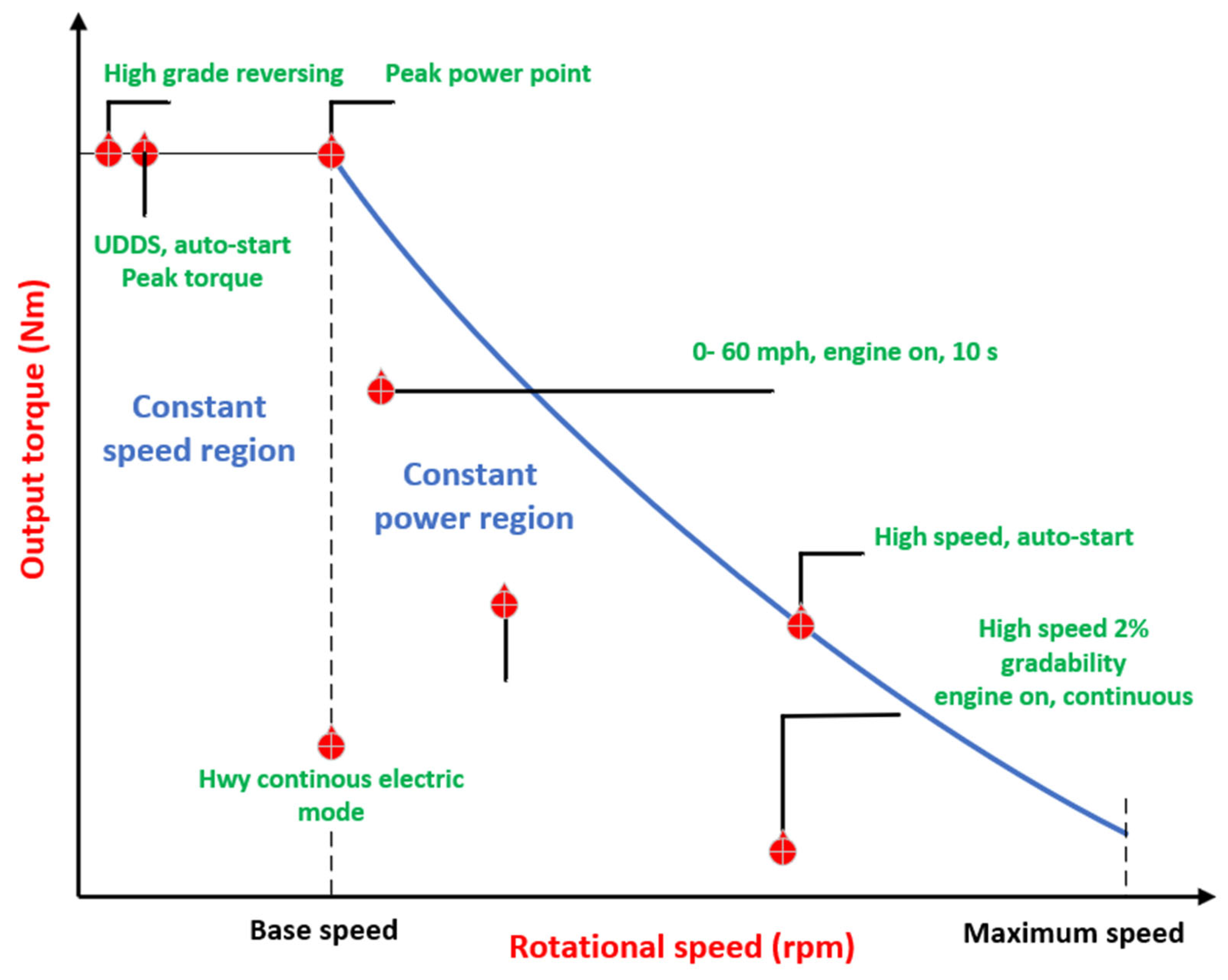
Figure 1. Torque-speed characteristics.
Electronics 14 03779 g001
Figure 2. Qualitative efficiency map.
Electronics 14 03779 g002
Figure 3. d-q mathematical model.
Electronics 14 03779 g003
Figure 4. Field-oriented control system.
Electronics 14 03779 g004
Figure 5. Angle β in the I d - I q plane.
Electronics 14 03779 g005
Figure 6. Classification diagram of the MTPA strategies.
Electronics 14 03779 g006
Figure 7. General diagram of electric drives using MTPA methods.
Electronics 14 03779 g007
Figure 8. Different topologies for the PMSM’s magnet positions.
Electronics 14 03779 g008
Figure 9. Inductor saturation characteristics.
Electronics 14 03779 g009
Figure 10. Phasor diagram of PMSM.
Electronics 14 03779 g010
Figure 11. Current circumference and voltage ellipse constrains in the d-q current frame.
Electronics 14 03779 g011
Figure 12. Current trajectory of PMSM when ( I m a x   > I S C ).
Electronics 14 03779 g012
Figure 13. Current trajectory of PMSM when ( I m a x < I S C ) .
Electronics 14 03779 g013
Figure 14. Effective operation regions of IPMSM in the torque–speed plane.
Electronics 14 03779 g014
Figure 15. Trajectories for the MTPA and the MTPV in the FW control at very high speeds.
Electronics 14 03779 g015
Figure 16. Torque vs. speed characteristics.
Electronics 14 03779 g016
Figure 17. Power vs. speed characteristics.
Electronics 14 03779 g017
Figure 18. Flux-weakening control method classification.
Electronics 14 03779 g018
Figure 19. Analytical direct calculation method.
Electronics 14 03779 g019
Figure 20. Improved LUT open control loop.
Electronics 14 03779 g020
Figure 21. FW SCR-VAC.
Electronics 14 03779 g021
Figure 22. UDFVC proposed control scheme.
Electronics 14 03779 g022
Figure 23. Torque flux control of IPMSM with 2D-LUTs.
Electronics 14 03779 g023
Figure 24. Variation of i d current.
Electronics 14 03779 g024
Figure 25. Variation in phase angle of current vector.
Electronics 14 03779 g025
Figure 26. Control of phase angle of current vector.
Electronics 14 03779 g026
Figure 27. Basic switching regulation technique in the suggested method.
Electronics 14 03779 g027
Figure 28. Different classification of FW control methods.
Electronics 14 03779 g028
Figure 29. Feed-forward technique.
Electronics 14 03779 g029
Figure 30. Feedback control technique.
Electronics 14 03779 g030
Figure 31. Hybrid FW Technique.
Electronics 14 03779 g031
Table 1. Comparison of the main characteristics of IMs, PMSMs, SRMs, and PM-assisted SynRMs.
FeaturesIMPMSMSRMPM-Assisted SynRM
Torque rippleLowLowVery highLow
Wide speed rangeNoYesYesYes
Fault toleranceNoYesYesYes
Close loop control simplicityYesYesYesYes
Preferred torque control methodFOC, DTCFOC, DTCDITC, ADITC, IDITCFOC, DTC
ReliabilityHighModerateModerateModerate
Flux-weakening capabilityYesYesYesYes
Power density/Current2.5 KW/I3.3–10.2 KW/I2.6–4.5 KW/I6.8 KW/I
Efficiency at constant torque79–86%91.3–95.8%85.1–89%87–93%
CostMediumHighLowMedium
Table 2. Comparison of flux-weakening control methods’ main advantages and shortcomings.
Control MethodProsConsKey References
Analytical Direct Calculation MethodGood choice for high-power motors with small stator resistance; Nice transient response; Stable transition between LBEMF and FWNot effective in MTPV region (though potentially extendable to it); Susceptible to machine parameter variations; Requires additional computation time for d–q current calculation; Neglects magnetic saturation effects[89,90,91,83]
Direct Open-loop Algorithm with Experimental LUTNo need for complex mathematical equations or real-time computationDepends on accurate inductance characterization (cross-magnetization and saturation effects); Inverter follows the torque reference without considering magnetic saturation; Requires large experimental setup and significant LUT memory; Time-consuming and risky experimental tuning process[92,93,100,101,102]
Single Current Regulator (SCR)No conflict between d- and q-axis current regulators in FW mode (single regulator simplifies control)Easily drives the inverter into voltage saturation (since the single current controller operates near the maximum voltage limit); Possible instability due to interaction of two current components in deep FW; Non-smooth switching between LBEMF (MTPA) and FW modes; Stability is very sensitive to the current limit setting and controller parameter values[53,93,103]
Unified Direct Flux Vector Control (UDFVC)Appropriate for many types of AC machines; Direct flux control through a single regulation channel for torque setpoints; Experimentally validated as a reliable method to find maximum load torqueRequires a flux observer which depends on accurate machine parameters; Does not operate in the MTPV region (limited high-speed capability)[105,106,107,108,109,110,111,112,113,114,104,115]
Torque and Flux Control (TFC) with LUTsDecreases flux and torque ripple compared to classic DTC; Considers magnetic saturation effects in controlRequires large memory to store extensive 2D- and 1D- LUTs; Potential control conflicts if multiple controllers operate simultaneously in FW; Many offline measurements needed to populate the LUTs[87,90,92,84,117,118,119,120,121,122,123]
Table 3. Comparison of VCC-based FW control implementations for different machine types (IPMSM, SPMSM, SyRM).
Machine TypeReference SignalReference SystemCoordinate SystemControl
Implementation
Transition to FWReference
IPMSMSpeedRealCartesiand-axis currentContinuous[120]
IPMSMTorqueRealCartesiand-axis currentContinuous[93]
SyRMSpeedPer-unitPolarCurrent angleContinuous[134]
IPMSMSpeedRealCartesiand-axis currentContinuous[131]
IPMSMSpeedRealCartesiand-axis currentSwitched[121]
IPMSMTorqueRealPolarCurrent angleContinuous[125]
SPMSMSpeedRealCartesiand–q axis currentsSwitched[123]
Disclaimer/Publisher’s Note: The statements, opinions and data contained in all publications are solely those of the individual author(s) and contributor(s) and not of MDPI and/or the editor(s). MDPI and/or the editor(s) disclaim responsibility for any injury to people or property resulting from any ideas, methods, instructions or products referred to in the content.