Abstract
The transfer-efficient power allocation problem for downlink simultaneous wireless information and power transfer (SWIPT) is investigated in massive multiple-input multiple-output (MIMO) systems in this paper. In the considered system, the base station (BS) equipped with a large number of antennas simultaneously transmits information and sends energy signals to multiple information and energy terminals equipped with a single antenna. The aim is to maximize transfer efficiency while meeting quality-of-service (QoS) requirements for all terminals. First, the closed-form expressions of achievable rates for each information terminal and the harvested energy for each energy terminal are obtained. Then, two optimization problems are formulated according to the obtained expressions, with the purpose of maximizing information transfer efficiency (ITE) and energy transfer efficiency (ETE). The maximizations of ITE and ETE are fractional programming problems and are difficult to solve directly. For this reason, the iterative optimization algorithm is proposed to solve the ITE maximization problem by transforming it into a subtractive form and then utilizing a successive convex approximation (SCA) method. Following a similar approach, another iterative optimization algorithm is proposed to solve the ETE maximization problem by transforming it into a subtractive form and then utilizing a linear programming method. Finally, numerical results demonstrate that the two iterative optimization algorithms can achieve good ITE and ETE, and we also reveal the trade-off between them in this work.
1. Introduction
With the rapid advancement of wireless communication technology, wireless communication networks are evolving from the fifth generation (5G) to beyond 5G (B5G) and even to the sixth generation (6G) [1,2]. The number of data services and terminals in wireless networks is constantly increasing, which leads to a rising energy consumption. In order to cope with this challenge, massive MIMO systems, where BSs are equipped with a large number of antennas, will play an important role in 5G and B5G or 6G because they can provide high energy efficiency (EE) levels [2,3,4,5]. Hence, EE investigations for massive MIMO systems have attracted a lot of attention in academic and industrial fields.
EE is normally defined as the ratio of the achievable sum rate to the total power consumption in bits/Joule [6,7]. In recent years, a number of EE investigations for massive MIMO systems have been performed, and some of the pivotal related studies are summarized as follows. The authors of [8] optimized the number of base station (BS) antennas to maximize EE in massive MIMO systems with SWIPT. The authors of [9] investigated EE in distributed massive MIMO systems and proposed an algorithm to maximize EE by jointly optimizing power allocation, user association, and antenna activation. By utilizing a reconfigurable intelligent surface (RIS), authors addressed the EE maximization problem in the massive MIMO downlink system with zero-forcing (ZF) precoding in [10]. In [11], the authors investigated EE in multi-cell massive MIMO downlink systems and developed a max–min EE optimization problem in terms of both concentration and distribution. Through multi-cell massive MIMO beamforming, the authors of [12] considered the problem of maximizing EE under minimum throughput constraints for a large number of uses. In [13], the authors maximized EE by employing joint system-level optimization to reach the green design target on massive MIMO downlink systems with SWIPT according to a power-splitting (PS) scheme. The authors of [14] investigated the efficient downlink power control strategies for massive MIMO systems according to two simple and efficient power control schemes, namely equal power allocation and max–min fairness power control. The authors of [15] considered the basic power allocation problem in cell-free massive MIMO systems, where they maximized the sum EE under the constraint of sum power at each access point and the constraint of a QoS requirement for each user. In order to maximize EE, the authors solved a precoding problem in multi-user massive MIMO downlink systems with low-resolution digital-to-analog and analog-to-digital converters in [16]. By deactivating part of the phase shifters, the authors proposed a method of EE beamforming, utilizing a large number of antennas for user-wise asymmetric uplink–downlink transportation in [17]. In [18], the authors proposed the joint framework for reducing signaling and computations to optimize EE in cell-free massive MIMO systems. By jointly optimizing the number of BS antennas, the number of served users, and the transmission power, the authors of [19] maximized the EE of uplink and downlink systems in practical massive MIMO systems with hardware impairments. In [20], the authors optimized power allocation of maximizing EE and analyzed the effects of backhaul power consumption, the number of access points, and the number of antennas at each access point. The authors proposed a more general EE model by considering power amplifier efficiency and optimized power allocation according to ZF precoding, which ensures the spectral efficiency and EE simultaneously in [21].
It is noted that the system performance metric EE in [8,9,10,11,12,13,14,15,16,17,18,19,20,21] refers to ITE. However, with the development of the Internet of Things, energy terminals, only for energy harvesting, also appear in wireless communication systems. In such systems, the BS transmits the hybrid signals of information and energy to information and energy terminals, respectively. Thus, ETE should be taken into account for such SWIPT systems. Currently, only a small amount of research has been performed according to the existing literature. In [22], the authors were able to maximize the minimum energy harvested by all energy terminals while meeting the achievable rate requirements of all information terminals in a massive MIMO SWIPT downlink system. In a multi-cell massive multiple-input single-output (MISO) SWIPT network, the authors maximized ETE of energy terminals while guaranteeing the QoS constraint for each information terminal in [23]. In [24], the authors proposed a multi-objective optimization framework to study ITE, ETE, and the relationship between ITE and ETE in a massive MIMO SWIPT downlink system. In [25], the authors proposed the three optimization problems, with the purposes of achievable sum rate maximization, harvested sum energy maximization, and joint QoS requirement maximization. Nevertheless, the authors of [22,23] studied the performance analysis only for energy terminals and no attention is paid to the performance analysis of information terminals, which is obviously incomplete from the perspective of system performance analysis. The system model in [24] only involves an information terminal, which is difficult to match with actual scenarios from the perspective of system models. Although a comprehensive analysis in [25] is conducted from the perspectives of performance analysis and system models, further performance analysis is still necessary.
Based on the above observations, especially [22,23,24,25], a comprehensive investigation is provided for massive MIMO systems with hybrid signal transfer of information and energy in this paper. In detail, compared with [22,23], the performance analysis of information terminals is added in this paper. Compared with [24], more information terminals are considered in this paper. Compared with [25], a new performance metric is analyzed in this paper. The aims are to maximize ITE and ETE by optimizing power allocation at the BS. To the best of our knowledge, such a study is not found in the existing literature. The main contributions of this study are summarized as follows:
- The massive MIMO downlink system with hybrid signal transfer of information and energy is investigated in the paper. The closed-form expression of achievable rate is obtained for each information terminal based on maximum-ratio (MR) precoding. The closed-form expression of harvested energy is also obtained for each energy terminal based on energy beamforming.
- The ITE maximization problem under the achievable rate requirement at each information terminal and limited power budget for information terminals is formulated. The ETE maximization problem under the harvested energy requirement at each energy terminal and limited power budget for energy terminals is formulated. The two problems are fractional programming problems and are very difficult to solve directly. To provide solutions, two corresponding algorithms for the two problems are respectively proposed by a series of mathematical analyses.
- The effectiveness of two algorithms is demonstrated by numerical results. The ITE maximization algorithm indicates that ITE first increases and reaches a maximum value with power budget for information terminals in the low-power domain, and then it decreases slowly in the high-power domain. The ETE maximization algorithm reveals that ETE first increases slowly and then rises rapidly with power budget for energy terminals in the low-power domain, however, ETE saturates gradually in the high-power domain. In addition, the trade-off between ITE and ETE is also shown.
The remaining part of the paper is organized as follows: Section 2 presents the transportation model of downlink SWIPT in massive MIMO systems. Section 3 formulates the maximization problems of ITE and ETE. The optimization algorithms of ITE and ETE are proposed in Section 4. Numerical results demonstrate the designed optimization algorithms of ITE and ETE in Section 5. Finally, the whole paper is concluded in Section 6.
A normal lowercase or uppercase letter denotes the scalar. A bold lowercase or uppercase letter denotes the vector or matrix, respectively. The symbol represents the identity matrix of size . The symbol stands for the mathematical expectation of a random variable. The symbols and represent the absolute value and Euclidean norm, respectively. The symbol stands for the diagonal function matrix. The symbol represents the minimum element from the given set. The symbols ,, and denote the Hermitian transpose, regular transpose, and inverse of a matrix respectively. The symbol stands for the circular symmetric complex-Gaussian distribution. Finally, the symbol represents the maximum value between its argument and zero.
2. System Model
Figure 1 shows the schematic diagram of a massive MIMO downlink system with the hybrid signals of information and energy. This considered system consists of one BS employing antennas, information terminals, and energy terminals. Each information or energy terminal employs a single antenna. The total number of information and energy terminals is . The BS simultaneously serves terminals in the same time–frequency resource. The time-division duplex (TDD) mode is operated in this system. A schematic diagram of the coherence interval is given in Figure 2. It is assumed that the channels between BS antennas and each terminal are constant and frequency-flat in a coherence interval of length symbols. In detail, symbols are used for channel estimation on the uplink, so the remaining portion of a coherence block including symbols is dedicated to hybrid signals of information and energy transmission on the downlink. One can also analyze uplink performance, but it will be left for future work due to space limitations.
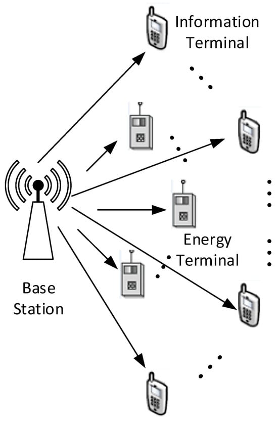
Figure 1.
A massive MIMO downlink system where BS transmits hybrid signals of information and energy to information and energy terminals.

Figure 2.
Every coherence interval includes two phases: uplink pilot phase and downlink information and power transfer phase.
The uncorrelated Rayleigh fading channels are considered in this paper, which means that all the channels are independent of each other. In order to facilitate subsequent derivations, the sets of and are denoted as the indices of information terminals and energy terminals, respectively. Mathematically, each channel vector is a realization of the circularly symmetric complex-Gaussian distribution and it can be modeled as
The variance in Equation (1) describes the large-scale fading symbolizing the attenuation of signals because of a long-distance propagation between BS antennas and terminals and because of diffraction around large obstacles. The vector in (1) represents the small-scale fading coefficients and every element follows .
2.1. Uplink Channel Estimation
The BS in a massive MIMO system needs to know channel state information (CSI) in order to leverage benefits of its antennas, for example, to coherently combine desired signals and reject interfering ones. However, the BS does not know CSI a priori, which calls for CSI estimation from uplink pilot sequences transmitted by all terminals during the first phase of every coherence interval. To avoid pilot interference, the pilot sequences transmitted by terminals are mutually orthogonal such that
where denotes the length of every pilot sequence, and and stand for pilot sequences transmitted by terminal and , respectively. After the pilot sequence signals transmitted by all terminals propagate on the uplink, the received signals at BS antennas can be written as
where is channel matrix, is diagonal power matrix of pilot sequences, is pilot sequence matrix, and is additive white Gaussian noise (AWGN) matrix with its independent elements following the distribution . According to the received pilot signal (3), the BS can use the minimum mean square error (MMSE) method to estimate the channel of information or energy terminal according to the following equation:
Then, the MMSE estimation of the channel is
and estimation error is
As a result, the channel estimate and estimation error are independent of each other, and their distribution can be written as
where
Since the BS obtains the CSI on the uplink, the CSI on the downlink can be known easily by virtue of TDD channel reciprocity.
2.2. Downlink SWIPT
During the second phase of every coherence interval, the BS transmits hybrid signals of information and energy to the information and energy terminals it serves. The transmitted signal at the BS can be expressed as
In Equation (10), the scalar symbols and stand for the transmit power allocated to information terminal and energy terminal , respectively, and the linear precoding vectors and stand for the information beamforming and energy beamforming for information terminal and energy terminal , respectively. In addition, the scalar and are the information symbol and energy symbol for information terminal and energy terminal , respectively, which are independent of each other and satisfy and with arbitrary distributions [26,27,28].
It is assumed that the BS uses MR precoded information data before transmission. According to [29], the precoding vectors can be expressed as
According to [30], the MR precoder is optimal for energy transfer and thus the energy beamforming vector can be described as
Note that the energy signal is a deterministic pseudo-random sequence and known to information terminals. Thus, the interference from energy signals can be completely cancelled at information terminals [24]. The received signal at an arbitrary information terminal can be expressed as
where is the additional AWGN and follows . The received signal at an arbitrary energy terminal can be written as
where is the additional AWGN and follows .
3. Transfer Efficiency Problem Formulations
The closed-form expressions of achievable rate for each information terminal and harvested energy for each energy terminal are obtained respectively, and then ITE and ETE optimization problems are formulated respectively according to the obtained expressions in this section.
3.1. ITE Problem Formulation
The achievable rate for each information terminal is given first in this subsection, which can be derived according to (13). According to [25,31,32,33], a lower bound of ergodic achievable rate (bits-per-second) for an arbitrary information terminal can be expressed as
where stands for system bandwidth and is signal-to-interference-and-noise ratio (SINR) which can be expressed as
Note that the interference from energy signals is removed since energy signals can be known to information terminals. As a similar derivation can be found in [34], the detailed proof processes are ignored here. According to (15), the sum achievable rate of all information terminals is written as
The total power allocation consumption for information terminals can be modeled as
In (18), stands for the inverse of power amplifier efficiency and represents the fixed circuit power consumption of the BS.
Since the sum achievable rate and the total power consumption for information terminals have been obtained through (17) and (18), the ITE problem is formulated as
where is a -dimensional power allocation vector of information terminals that gathers the elements of , is the minimum achievable rate requirement of each information terminal, and denotes the maximum transmit power allocated by the BS for all information terminals.
Note that the objective function in (19) can be always satisfied when the number of BS antennas is large enough and the power allocated by the BS for information terminals is high enough based on (15). Thus, in what follows, it is assumed that the ITE problem is feasible.
3.2. ETE Problem Formulation
In the following, the harvested energy of each energy terminal will be analyzed. A simple linear EH model is considered in the paper and a non-linear EH model is left for future work. The normalized energy unit (Joules-per-second) is used in this paper. According to [24], the terms “power” and “energy” are equivalent. As the ambient noise cannot be harvested [30], according to (14), the harvested energy by an arbitrary energy terminal can be written as
where stands for the conversion efficiency of EH. Based on the results in the previous work [25], can be easily calculated as
According to (21), the sum harvested energy of energy terminals can be written as
The total power allocation consumption for energy terminals can be modeled as
Since the sum harvested energy and the total power consumption for energy terminals have been obtained through (22) and (23), the ETE problem is formulated as
where is a -dimensional power allocation vector of energy terminals that gathers the elements of , represents the minimum requirement of harvested energy for each energy terminal, and stands for the maximum allocated power for all energy terminals.
Note that the first constraint in (24) can always be satisfied when the number of BS antennas is large enough and the power allocated by BS for energy terminals is high enough according to (21). Hence, in what follows, it is assumed that the ETE problem is feasible.
4. Power Allocation Optimizations
The optimal power allocation at the BS is investigated for ITE and ETE problems, respectively, in this section.
4.1. Power Allocation for Maximizing ITE
It is easy to observe from (19) that the ITE problem is not linear and convex, and thus it is very difficult to solve directly. In order to obtain a solution, the reformulation, SCA, and Lagrange dual are introduced in the following.
Obviously, as the ITE problem is a classical fractional programming problem, it can be transformed into a tractable form by adopting the common approach in [35]. By adopting this approach, the objective function (19) is reformulated into the following univariate equation:
Theorem 1.
If is the optimal solution of (19), and is the corresponding optimal ITE, then
Proof.
The proof can be found in Appendix A. □
Theorem 1 shows that if the parameter which can satisfy (25) can be found, the solution of (25) is also that of the original ITE problem (19). As revealed in [35], the function is strictly decreasing and continuous, and the equation has a unique solution. Under these properties, the optimal can be obtained with one-dimension search interval . According to [34], is set to 0 and is set to an infeasible point. Among one-dimension search methods, the bisection method is efficient to find [36].
With the obtained , the ITE problem (19) can be reformulated as
Although the fractional structure vanishes from (19), the objective function in (28) is not still convex and it is hard to find an accurate solution. However, according to [37], the SCA method can be used to approximate the objective function in (28) into a series of concave functions. Then, the lower bound of can be expressed as
which is tight when
Let and be the vectors stacked by every and every according to their index. The objective function in (28) is rewritten as
is obtained by submitting into (17). Equation (32) is still non-concave, then can be introduced to turn (32) into a concave form. Furthermore, with , (32) can be expressed as the sum of concave and linear terms because the log-sum-exp is a convex function. As a result, the ITE problem (19) turns into the following optimization problem:
The optimization problem (33) can be solved by the Lagrange dual method. By rearranging terms, the Lagrange can be expressed as
where and are Lagrange multipliers. Then, the dual function is given as
Equation (35) can be solved by dividing it into two loops: the inner loop maximizing for given and the outer loop minimizing for given .
Inner loop: By differentiating with respect to and then transforming back to with , the Karush–Kuhn–Tucker condition can be written as
It is observed from (36) that can be found in the denominator of the right-hand side of (36), which means that a closed-form expression of can be obtained. However, it is a fixed-point problem, which is solved by iterations.
Theorem 2.
The in (36) always converges to the unique fixed point under any initial value, which is to maximize .
Proof:
The proof can be found in Appendix B. □
Outer loop: If the optimal is obtained by (36), a subgradient method can be used to update the Lagrange multipliers as follows:
where stands for iteration index and and represent sizes of iteration steps. The dual optimal point can be obtained when Lagrange multipliers converge. According to [38], the duality gap is ensured to be zero because the inner loop is convex.
Now, the whole process including three aspects is summarized. First, according to Theorem 1, the ITE problem of Problem (19) is transformed into (28) in order to avoid the fractional structure. Then, due to the non-concavity of the reformulated objective function, the SCA method is utilized to turn it into concave functions. Finally, the Lagrange dual method is used to solve these concave functions.
According to the above analyses, an iterative algorithm framework can be outlined for the ITE problem of (19), which is presented in Algorithm 1 and named the ITEM algorithm.
| Algorithm 1 ITEM algorithm to obtain optimal power allocation for information terminals. |
| Input: maximum tolerance for bisection method, SCA, and Lagrangian dual method, respectively, maximum number of iterations for SCA and Lagrangian dual method, respectively, and ITE search interval . Output: and . while ; Initialize and ; ; ; while or ; calculate via (36) using fixed point iterations; update and via (30) and (31); calculate ; end while calculate via (16) with ; update and via (30) and (31), respectively. calculate ; end while calculate via (25); If , let , otherwise, let ; end while Denote and . |
Then, the convergence of the ITEM algorithm mainly depends on three loops. The loops of carrying out the bisection method and Lagrange dual method are standard convex optimization problems and thus their convergence can be guaranteed. The loop of carrying out the SCA method can produce a monotonically increasing function and can achieve the global optimum in most cases or a local optimum at least when the initial values are set as and according to [37]. Therefore, it can be concluded that the convergence of the ITEM algorithm can be guaranteed.
In addition, the computational complexity of the ITEM algorithm can be roughly written as , where is the number of required iterations for updating , is the number of required iterations for updating and , and is the complexity of the Lagrange dual method.
4.2. Power Allocation for Maximizing ETE
In this section, the ETE problem (24) will be analyzed and solved. Based on Theorem 1, the fractional structure of the objective function in (24) is turned into an equivalent but more tractable form. Accordingly, the ETE problem (24) can be reformulated as
Similar to the process of solving the ITE problem, the optimal is the solution of and can be obtained by the bisection method. Plugging (21) and (22) into the objective function in (39), it is expressed as
According to (40), it can be concluded that the objective function in (39) is the linear combination of , for , when and are given. Moreover, the constraints in (39) are affine functions of , for . Thus, the ETE problem (39) is a linear programming one and is solved by the interior point method. As the linear program is a standard method in optimization, its detailed processes are ignored here.
Similar to the ITEM algorithm, another iterative algorithm framework for the ETE problem in (24) is presented in Algorithm 2 and named the ETEM algorithm. According to [34], can be set to be 0 and can be set to be an infeasible point.
| Algorithm 2 ETEM algorithm to obtain optimal power allocation for energy terminals. |
| Input: maximum tolerance , power allocation for information terminals , and ETE search interval . Output: and . while ; calculate via linear programming based on (39); calculate ; If , let , otherwise, let ; end while Denote and . |
As the ETEM algorithm involves the bisection method and linear programming, which are standard convex optimization methods, its convergence can be ensured. Additionally, the computational complexity of the ETEM algorithm is roughly written as , where is the number of iterations required for updating and is the complexity to perform the linear programming method.
Finally, the optimal ITE and ETE can be obtained by ITEM and ETEM algorithms when power allocations for information terminals and energy terminals are given, respectively. is the maximum transmit power which is used at the BS for all terminals and satisfies . When performs a line search over through the proper step size, the corresponding can be obtained. Thus, the optimal ITE and ETE can be obtained at each iteration. As a result, the trade-off between ITE and ETE can be revealed.
5. Numerical Results
The numerical results are presented to verify ITE and ETE algorithms under various system parameter settings in this section. The analyzed massive MIMO SWIPT system comprises 1 BS, 10 information terminals, and 5 energy terminals. According to [22,24], information terminals are randomly distributed over a circular area with an inner radius of 20 m and outer radius of 100 m around the BS, and energy terminals are randomly distributed over a circular area with a radius of 20 m around the BS to facilitate EH. The number of BS antennas is set to be 200. The system bandwidth is 10 MHz and every coherence interval is set to be 200 symbols. The fixed power consumption for the BS is set to be 40 W. The power amplifier efficiency is set to be 4. The length of pilot sequences equals the number of all terminals and every terminal has a pilot symbol power of 200 mW. The large-scale fading can be modeled as , where represents the distance between information or energy terminal and BS, . The noise variance for and is set to be −96 dBm. The efficiency factor of the EH process for every energy terminal is set to be . The above parameters are used throughout numerical results unless otherwise stated.
The convergences of ITEM and ETEM algorithms are demonstrated first in Figure 3 and Figure 4 as they are iterative optimization methods. Without loss of generality, the maximum transmit powers allocated by the BS for information and energy terminals are set to be 30 dBm and 40 dBm, respectively, the minimum requirement of achievable rate for each information terminal is set to be 4 bit/s/Hz, 5 bit/s/Hz, and 6 bit/s/Hz, respectively, and the minimum requirement of harvested energy for each energy terminal is set to be 70 W, 80 W, and 90 W, respectively. From Figure 3 and Figure 4, it can be observed that ITEM and ETEM algorithms converge to the optimal values with 21 and 16 iterations, respectively. Therefore, it can be concluded that ITEM and ETEM algorithms are both convergent and have satisfactory convergence speeds. Moreover, it is found that both algorithms with higher QoS requirements have lower optimal values. This is reasonable because of the fact that a part of the whole performance has to be sacrificed to ensure higher QoS requirements for ITEM and ETEM algorithms. In addition, there are violent fluctuations in first several iterations for both algorithms. This is because the initial upper bounds for both algorithms do not belong to the feasible region. After they go into the feasible region through several iterations, both algorithms monotonously increase until convergence.
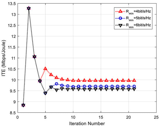
Figure 3.
The convergence of ITEM algorithm for information terminals.
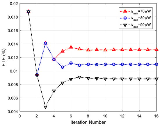
Figure 4.
The convergence of ETEM algorithm for energy terminals.
Figure 5 illustrates the impacts of power allocation on ITE under various numbers of BS antennas for information terminals. Without loss of generality, the minimum data rate requirement of each information terminal is set to be 4 bit/s/Hz. As shown in Figure 5, ITE increases monotonically with power allocation in the low-power domain and reaches the maximum value slowly, and then it decreases with power allocation in the high-power domain. This result reveals that, once the maximum ITE is achieved, any additional increase in power allocation will incur a loss of ITE. This is because an increase in effective data rate exceeds power consumption in the low-power domain, however, the case is the opposite in the high-lower domain. As a result, the former can improve ITE, but the latter decreases it. Therefore, there exists an optimal power allocation of ITE maximization for information terminals, which also verifies the feasibility of the ITEM algorithm. In addition, it is also found that increasing BS antennas is a better way to improve ITE than more power allocation. This is because more power allocation leads to stronger interference among information terminals, which decreases ITE, but more BS antennas do not.
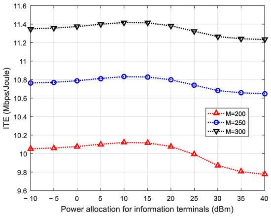
Figure 5.
ITE performance under various values of power allocation for information terminals.
Figure 6 investigates the impacts of power allocation on ETE under various numbers of BS antennas for energy terminals. Without the loss of generality, the minimum harvested energy requirement of each energy terminal is set to be 80 W and the power allocation for information terminals is set to 10 dBm. As shown in Figure 6, ETE increases slowly in the low-power domain and then rises rapidly with power allocation, but it saturates gradually in the high-power domain. The reason is that ETE is dominated by the fixed consumption from the circuit power when power allocation is very low, which results in a slow growth, and ETE is not sensitive to the consumption from the fixed circuit power and power allocation becomes significant when power allocation is in the high-power domain, which leads to ETE nearly holding steady. In other words, ETE has little benefit from too much high-power allocation. Therefore, there exists an optimal power allocation of ETE maximization for energy terminals, which also verifies the feasibility of the ETEM algorithm. In addition, it is also shown that increasing BS antennas is an effective way to improve ETE for energy terminals.
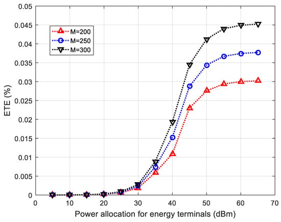
Figure 6.
ETE performance under various values of power allocation for energy terminals.
The impacts from the number of BS antennas on ITE and ETE based on different algorithms are shown in Figure 7 and Figure 8. For comparison purposes, the algorithms of equal power allocation where the BS equally allocates the transmit power to every terminal it serves, ITE based on the minimum achievable rate maximization, transmit power minimization, and achievable sum rate maximization algorithm in [25] and ETE based on the minimum energy harvesting maximization, transmit power minimization, and harvested sum energy maximization algorithm in [25] are introduced as baselines. The equal power allocation, the minimum achievable rate maximization, the minimum energy harvesting maximization, the transmit power minimization, the achievable sum rate maximization algorithm in [25], and the harvested sum energy maximization algorithm in [25] are respectively denoted by “EPA”, “MARM”, “MEHM”, “TPM”, “ASRM”, and “HSEM” in Figure 7 and Figure 8. For fair comparison, the minimum data rate and harvested energy requirements are set to zero. Experimental results show that both ITE and ETE based on different algorithms always increase with more and more BS antennas. Therefore, massive MIMO can bring significant improvement for ITE and ETE. Moreover, it is also observed that the ITEM algorithm gets a higher ITE than EPA, MARM, TPM, and ASRM algorithms in Figure 7 and the ETEM algorithm gets a higher ETE than EPA, MEHM, TPM, and HSEM algorithms in Figure 8 under the same number of BS antennas. These reveal the optimality of the proposed ITEM and ETEM algorithms.
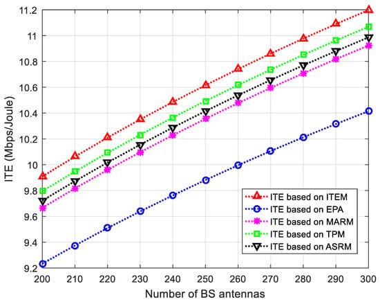
Figure 7.
ITE performance comparison based on different algorithms for information terminals.
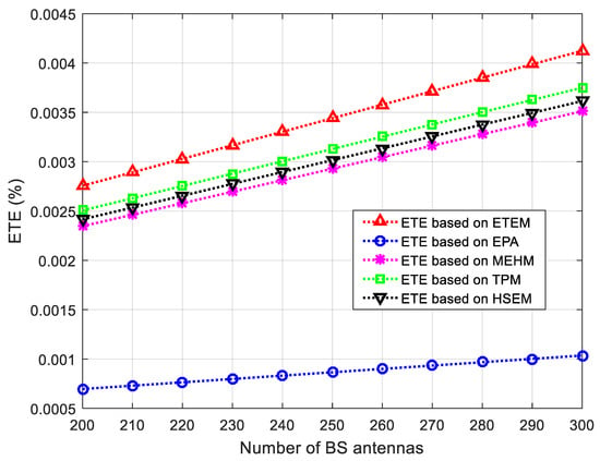
Figure 8.
ETE performance comparison based on different algorithms for energy terminals.
Figure 9 depicts the trade-off between ITE and ETE under different total transmit powers of the BS. Here, the total transmit power of the BS is the sum of power allocation for information terminals and energy terminals, respectively, i.e., . Without the loss of generality, the minimum requirement of achievable rate for each information terminal is set to 4 bit/s/Hz and the minimum requirement of harvested energy for each energy terminal is set to 70 W. Experimental results show that ITE is a monotonically decreasing function with ETE when the total transmit power of the BS is relatively low, such as dBm and dBm in Figure 9, and ITE first increases and then decreases with ETE when the total transmit power of the BS is relatively high, such as dBm and dBm in Figure 9. The results indicate that ITE and ETE are in conflict with each other in the low-power transmit domain of the BS, and ITE and ETE cannot achieved the maximum value at the same time in the high-power transmit domain of the BS.
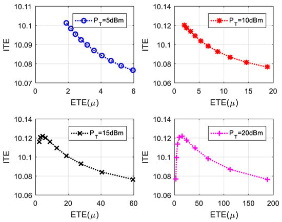
Figure 9.
The trade-off between ITE and ETE under different total transmit powers of BS.
6. Conclusions
This paper optimizes power allocation to maximize ITE and ETE for information and energy terminals, respectively, in massive MIMO downlink systems with downlink hybrid information and energy transfer. As the formulated optimization problems of ITE and ETE are fractional programming problems, which are very difficult to solve directly, two corresponding algorithms are proposed to solve them after a series of mathematical transforms. In addition, the convergence and complexity of the proposed algorithms are also analyzed. Finally, numerical results manifest that the proposed algorithms can provide good ITE and ETE for information terminals and energy terminals by power allocation in the studied system. Nevertheless, there are still some advanced technologies which can improve system transportation efficiency such as a solar-powered wireless solution [39], beam-scanning antenna array [40], etc. There are also some issues related to practical scenarios, such as hardware impairments [41], channel correlation [41], etc. They are both left for future work.
Author Contributions
Conceptualization, W.S. and H.Y.; methodology, W.S.; software, Y.M.; validation, formal analysis, and investigation, X.W.; resources and data curation, Y.M.; writing—original draft preparation and writing—review and editing, W.S.; supervision, project administration, and funding acquisition, H.Y. All authors have read and agreed to the published version of the manuscript.
Funding
This work is supported by Distributed Optical Fiber Temperature Sensors Based on the Raman Effect project under Grant 2424185, Flower Trading Platform Project under Grant 2424411, and Qingdao Agricultural University Doctoral Start-Up Fund under Grant 1123005.
Data Availability Statement
The original contributions presented in this study are included in the article. Further inquiries can be directed to the corresponding author.
Conflicts of Interest
The authors declare no conflicts of interest.
Correction Statement
This article has been republished with a minor correction to the Data Availability Statement. This change does not affect the scientific content of the article.
Appendix A
The sufficient condition of Theorem 1 is first proved, i.e., (27) can be obtained from (26). Let be the optimal solution of (19), then the following results can be obtained from (26):
According to (A1) and (A2), it can be easily concluded that (27) is valid and the maximum value of ITE can be achieved at . Therefore, the sufficient condition of Theorem 1 can be proved.
Next, the necessary condition of Theorem 1 is proved, i.e., (26) can be obtained from (27). Let be the optimal solution of (27), the following results can be presented as:
After simple operations for (A3), the results are given as
(A4) and (A5) mean that the maximum value of (19) is and is achieved at . Thus, the necessary condition of Theorem 1 can be proved.
To sum up, the proof of Theorem 1 is completed.
Appendix B
The right-hand side of (36) is expressed as
where is the identity column vector of size .
According to [42], if the properties of the positivity, the monotonicity, and the scalability of (A6) can be satisfied for any , the iteration of (A6) will converge to the unique fixed point under any initial value.
The positivity of (A6) is obvious because the power allocation for each information terminal is always non-negative.
By assuming that , , we have
which verifies the monotonicity of (A6).
Letting , we have
which shows the scalability of (A6).
To sum up, it can be concluded that (A6) can converge to the unique fixed point under any initial value. Then, Theorem 2 is proved.
References
- Morocho-Cayamcela, M.E.; Lee, H.; Lim, W. Machine Learning for 5G/B5G Mobile and Wireless Communications: Potential, Limitations, and Future Directions. IEEE Access 2019, 7, 137184–137206. [Google Scholar] [CrossRef]
- Zhang, J.; Bjrnson, E.; Matthaiou, M.; Ng, D.W.K.; Yang, H.; Love, D.J. Prospective Multiple Antenna Technologies for Beyond 5G. IEEE J. Sel. Areas Commun. 2020, 38, 1637–1660. [Google Scholar] [CrossRef]
- Rusek, F.; Persson, D.; Lau, B.K.; Larsson, E.G.; Marzetta, T.L.; Edfors, O.; Tufvesson, F.F. Scaling up MIMO: Opportunities and Challenges with Very Large Arrays. IEEE Signal Process. Mag. 2013, 30, 40–60. [Google Scholar] [CrossRef]
- Ngo, H.Q.; Larsson, E.G.; Marzetta, T.L. Energy and Spectral Efficiency of Very Large Multiuser MIMO Systems. IEEE Trans. Commun. 2013, 61, 1436–1449. [Google Scholar] [CrossRef]
- Interdonato, G.; Karlsson, M.; Bjornson, E.; Larsson, E.G. Local Partial Zero-Forcing Precoding for Cell-Free Massive MIMO. IEEE Trans. Wirel. Commun. 2020, 19, 4758–4774. [Google Scholar] [CrossRef]
- Buzzi, S.; Chih-Lin, I.; Klein, T.E.; Poor, H.V.; Yang, C.; Zappone, A. A Survey of Energy-Efficient Techniques for 5G Networks and Challenges Ahead. IEEE J. Sel. Areas Commun. 2016, 34, 697–709. [Google Scholar] [CrossRef]
- Zappone, A.; Sanguinetti, L.; Bacci, G.; Jorswieck, E.; Debbah, M. Energy-Efficient Power Control: A Look at 5G Wireless Technologies. IEEE Trans. Signal Process. 2016, 7, 1668–1683. [Google Scholar] [CrossRef]
- Wang, X.; Zhai, C. Simultaneous Wireless Information and Power Transfer for Downlink Multi-User Massive Antenna-Array Systems. IEEE Trans. Commun. 2017, 65, 4039–4048. [Google Scholar] [CrossRef]
- Dong, G.; Zhang, H.; Jin, S.; Yuan, D. Energy Efficiency-Oriented Joint User Association and Power Allocation in Distributed Massive MIMO Systems. IEEE Trans. Veh. Technol. 2019, 68, 5794–5808. [Google Scholar] [CrossRef]
- Souza, J.W.; Abrao, T. Energy Efficiency Maximization for Intelligent Surfaces-Aided Massive MIMO With Zero Forcing. IEEE Trans. Green Commun. Netw. 2024, 8, 802–814. [Google Scholar]
- You, L.; Huang, Y.; Zhang, D.; Chang, Z.; Gao, X. Energy Efficiency Optimization for Multi-Cell Massive MIMO: Centralized and Distributed Power Allocation Algorithms. IEEE Trans. Commun. 2021, 69, 5228–5242. [Google Scholar] [CrossRef]
- Nguyen, L.D.; Tuan, H.D.; Duong, T.Q.; Poor, H.V.; Hanzo, L. Energy-Efficient Multi-Cell Massive MIMO Subject to Minimum User-Rate Constraints. IEEE Trans. Commun. 2021, 69, 914–928. [Google Scholar] [CrossRef]
- Khodamoradi, V.; Sali, A.; Messadi, O.; Khalili, A.; Ali, B.M. Energy-Efficient Massive MIMO SWIPT-Enabled Systems. IEEE Trans. Veh. Technol. 2022, 71, 5111–5127. [Google Scholar] [CrossRef]
- Lee, B.M. Efficient Power Control Strategies for Massive MIMO in High-Density Massive IoT Networks. IEEE Internet Things J. 2024, 11, 21773–21787. [Google Scholar] [CrossRef]
- Mai, T.C.; Ngo, H.Q.; Tran, L.N. Energy Efficiency Maximization in Large-Scale Cell-Free Massive MIMO: A Projected Gradient Approach. IEEE Trans. Wirel. Commun. 2022, 21, 6357–6371. [Google Scholar] [CrossRef]
- Choi, J.; Park, J.; Lee, N. Energy Efficiency Maximization Precoding for Quantized Massive MIMO Systems. IEEE Trans. Wirel. Commun. 2022, 21, 6803–6817. [Google Scholar] [CrossRef]
- Xu, K.; Zheng, F.C.; Xu, H.G.; Zhu, X.; Xiong, X.G. Energy Efficient Beamforming for Millimeter-Wave Massive MIMO Systems Under User-Wise Asymmetric UplinkDownlink Traffic. IEEE Trans. Wirel. Commun. 2023, 22, 7522–7536. [Google Scholar] [CrossRef]
- Chen, S.F.; Zhang, J.Y.; Björnson, E.; Demir, Ö.T.; Ai, B. Energy-Efficient Cell-Free Massive MIMO Through Sparse Large-Scale Fading Processing. IEEE Trans. Wirel. Commun. 2023, 22, 9374–9389. [Google Scholar] [CrossRef]
- Liu, Z.H.; Lee, C.H.; Xu, W.J.; Li, S.Y. Energy-Efficient Design for Massive MIMO with Hardware Impairments. IEEE Trans. Wirel. Commun. 2021, 20, 843–857. [Google Scholar] [CrossRef]
- Ngo, H.Q.; Tran, L.N.; Duong, T.Q.; Matthaiou, M.; Larsson, E.G. On the Total Energy Efficiency of Cell-Free Massive MIMO. IEEE Trans. Green Commun. Netw. 2018, 2, 25–39. [Google Scholar] [CrossRef]
- Guo, Y.C.; Tang, J.L.; Wu, G.; Li, S.Q. Power allocation for massive MIMO: Impact of power amplifier efficiency. Sci. China-Inf. Sci. 2016, 59, 1–9. [Google Scholar] [CrossRef]
- Zhao, L.; Wang, X.D.; Zheng, K. Downlink Hybrid Information and Energy Transfer with Massive MIMO. IEEE Trans. Wirel. Commun. 2016, 15, 1309–1322. [Google Scholar] [CrossRef]
- Jang, S.; Lee, H.; Kang, S.; Oh, T.; Lee, I. Energy Efficient SWIPT Systems in Multi-Cell MISO Networks. IEEE Trans. Wirel. Commun. 2018, 17, 8180–8194. [Google Scholar] [CrossRef]
- Leng, S.; Ng, D.W.K.; Zlatanov, N.; Schober, R. Multi-objective beamforming for energy-efficient SWIPT systems. In Proceedings of the 2016 International Conference on Computing, Networking and Communications (ICNC), Kauai, HI, USA, 15–18 February 2016; Volume 16, pp. 1–7. [Google Scholar]
- Sun, W.F.; Li, J.Z. Power allocation optimization for hybrid information and energy transfer with massive MIMO downlink. IET Commun. 2023, 17, 1998–2008. [Google Scholar] [CrossRef]
- Zhang, R.; Ho, C.K. MIMO Broadcasting for Simultaneous Wireless Information and Power Transfer. IEEE Trans. Wirel. Commun. 2013, 12, 1989–2001. [Google Scholar] [CrossRef]
- Xu, J.; Liu, L.; Zhang, R. Multiuser MISO Beamforming for Simultaneous Wireless Information and Power Transfer. IEEE Trans. Signal Process. 2014, 62, 4798–4810. [Google Scholar] [CrossRef]
- Lee, H.; Lee, S.R.; Lee, K.J.; Kong, H.B.; Lee, I. Optimal Beamforming Designs for Wireless Information and Power Transfer in MISO Interference Channels. IEEE Trans. Wirel. Commun. 2015, 14, 4810–4821. [Google Scholar] [CrossRef]
- Björnson, E.; Larsson, E.G.; Debbah, M. Massive MIMO for Maximal Spectral Efficiency: How Many Users and Pilots Should Be Allocated? IEEE Trans. Wirel. Commun. 2016, 15, 1293–1308. [Google Scholar] [CrossRef]
- Yang, G.; Ho, C.K.; Zhang, R.; Guan, Y.L. Throughput Optimization for Massive MIMO Systems Powered by Wireless Energy Transfer. IEEE J. Sel. Areas Commun. 2015, 33, 1640–1650. [Google Scholar] [CrossRef]
- Dai, Y.; Dong, X. Power Allocation for Multi-Pair Massive MIMO Two-Way AF Relaying with Linear Processing. IEEE Trans. Wirel. Commun. 2016, 15, 5932–5946. [Google Scholar] [CrossRef]
- Hassibi, B.; Hochwald, B.M. How much training is needed in multiple-antenna wireless links? IEEE Trans. Inf. Theory 2003, 49, 951–963. [Google Scholar] [CrossRef]
- Jose, J.; Ashikhmin, A.; Marzetta, T.L.; Vishwanath, S. Pilot Contamination and Precoding in Multi-Cell TDD Systems. IEEE Trans. Wirel. Commun. 2011, 10, 2640–2651. [Google Scholar] [CrossRef]
- Chien, T.V.; Björnson, E.; Larsson, E.G. Joint Power Allocation and User Association Optimization for Massive MIMO Systems. IEEE Trans. Wirel. Commun. 2016, 15, 6384–6399. [Google Scholar] [CrossRef]
- He, S.; Huang, Y.; Jin, S.; Yang, L. Coordinated Beamforming for Energy Efficient Transmission in Multicell Multiuser Systems. IEEE Trans. Commun. 2013, 61, 4961–4971. [Google Scholar] [CrossRef]
- Zhou, T.; Huang, Y.; Yang, L. Energy-efficient user association in downlink heterogeneous cellular networks. IET Commun. 2016, 10, 1553–1561. [Google Scholar] [CrossRef]
- Papandriopoulos, J.; Evans, J.S. SCALE: A Low-Complexity Distributed Protocol for Spectrum Balancing in Multiuser DSL Networks. IEEE Trans. Inf. Theory 2009, 55, 3711–3724. [Google Scholar] [CrossRef]
- Chen, Q.; Yu, G.; Yin, R.; Li, G.Y. Energy-Efficient User Association and Resource Allocation for Multistream Carrier Aggregation. IEEE Trans. Veh. Technol. 2016, 65, 6366–6376. [Google Scholar] [CrossRef]
- Bono, F.M.; Polinelli, A.; Radicioni, L.; Benedetti, L.; Castelli-Dezza, F.; Cinquemani, S.; Belloli, M. Wireless Accelerometer Architecture for Bridge SHM: From Sensor DesigntoSystemDeployment. Future Internet 2025, 17, 29. [Google Scholar] [CrossRef]
- Wang, S.; Wang, W.; Zheng, Y. Dual-Functional Quasi-Uniform Beam-Scanning Antenna Array with Endfire Radiation Capability for Integrated Sensing and Communication Applications. IEEE Trans. Veh. Technol. 2025, 14, 1–11. [Google Scholar] [CrossRef]
- Björnson, E.; Hoydis, J.; Sanguinetti, L. Massive MIMO Networks: Spectral, Energy, and Hardware Efficiency. Found. Trends Signal Process. 2017, 11, 154–655. [Google Scholar] [CrossRef]
- Yates, R.D. A framework for uplink power control in cellular radio systems. IEEE J. Sel. Areas Commun. 1995, 13, 1341–1347. [Google Scholar] [CrossRef]
Disclaimer/Publisher’s Note: The statements, opinions and data contained in all publications are solely those of the individual author(s) and contributor(s) and not of MDPI and/or the editor(s). MDPI and/or the editor(s) disclaim responsibility for any injury to people or property resulting from any ideas, methods, instructions or products referred to in the content. |
© 2025 by the authors. Licensee MDPI, Basel, Switzerland. This article is an open access article distributed under the terms and conditions of the Creative Commons Attribution (CC BY) license (https://creativecommons.org/licenses/by/4.0/).