Article

The Design of a Dual-Band 4-Port Magnetic Resonant Wireless Power Transfer Coupler: Theoretical Analysis of Losses and Interference for Biomedical Wearable Applications

1
Department of ICT Convergence, Soonchunhyang University, Asan 31538, Republic of Korea
2
Department of Electronic Engineering, Soonchunhyang University, Asan 31538, Republic of Korea
*
Author to whom correspondence should be addressed.
Electronics 2025, 14(18), 3637; https://doi.org/10.3390/electronics14183637
Submission received: 4 August 2025 / Revised: 8 September 2025 / Accepted: 12 September 2025 / Published: 14 September 2025

Abstract

This study analyzes cross-band interference and losses in a compact dual-frequency 4-port inductive coupler operating at 6.78 MHz and 13.56 MHz for Magnetic Resonant Wireless Power Transfer (MR-WPT) using an equivalent circuit model fitted to 3D full wave analysis and empirical measurements. The model is first matched to idealized 3D model results to establish baseline parameters and then theoretically analyzed in relation to measured S-parameters to reflect empirical losses. This approach achieves accurate theoretical interpretation, with errors remaining below 5%. The results show consistent transmission coefficients, with the model most closely matching the measurements. Power loss and efficiency comparisons indicate that the model accurately captures deviations, with its performance positioned between the 3D full wave analysis and measured results. Cross-band interference remains below −20 dB, and the maximum measured efficiency reaches 71.18%.

1. Introduction

Wireless Power Transfer (WPT) has emerged as a critical technology for powering biomedical wearable devices [1,2], eliminating the need for batteries that pose risks of leakage, limited lifespan, and surgical replacement [3,4]. This integration enables continuous monitoring of physiological parameters such as heart rate, blood glucose, and neural activity in wearable sensors, facilitating non-invasive healthcare solutions with enhanced patient comfort and safety. The electromagnetic coupling in WPT systems allows for energy delivery through skin barriers, supporting applications in smart patches and implantable monitors for chronic disease management. Recent advancements have further emphasized WPT’s role in Internet of Medical Things (IoMT), where seamless power supply is essential for real-time data transmission in remote patient monitoring [5,6,7].
Multi-coil structures are incorporated in WPT to improve power transfer efficiency (PTE) and extend operational range, particularly in biomedical contexts where misalignment or tissue attenuation can degrade performance [8,9,10,11]. These configurations, such as 3-coil or 4-coil links, utilize intermediate coils to enhance magnetic resonance and reduce electromagnetic energy absorption in tissues, ensuring compliance with specific absorption rate (SAR) limits while maintaining stable power delivery to implants or wearables [12]. The use of multiple coils also allows for better spatial freedom, accommodating dynamic body movements in wearables like fitness trackers or cardiac monitors, thus reducing power drop-offs due to positional variations.
Such use of multi-coil structures naturally enables dual-band WPT, allowing for simultaneous power delivery and data communication at distinct frequencies (e.g., 6.78 MHz for power, 13.56 MHz for data) [13,14,15], which is required for multi-functional biomedical wearables like neural stimulators needing both energy replenishment and telemetry [16,17,18]. In wearable applications, this facilitates efficient operation in dynamic environments, minimizing interference and optimizing energy harvest from ambient sources for continuous health monitoring. Dual-band operation further addresses bandwidth constraints in single-frequency systems, enabling higher data rates for telemetry while maintaining robust power transfer, crucial for applications like continuous glucose monitoring or EEG devices where both energy and information flow are vital [19].
Study on dual-band WPT for biomedical devices typically concentrates on efficiency at single frequencies or under idealized conditions. Such work often neglects cross-band interference and tissue-induced losses in multi-port configurations [20,21]. The oversight results in restricted real-world applicability and underestimation of power leakage in wearables [18]. These gaps emphasize the requirement for advanced models that incorporate empirical fitting to handle practical losses effectively. Certain studies examine multi-coil designs to boost PTE, but few tackle the interactions between dual frequencies in compact setups. Biological tissues further complicate electromagnetic fields in these systems.
This paper addresses the limitations of existing dual-band WPT models by developing a practical equivalent circuit (PEC) fitted to HFSS simulations and empirical measurements, thereby improving loss and interference predictions in compact 4-port inductive couplers. Through this fitting approach, the study analyzes power loss, efficiency, and cross-band interference to propose a robust framework for optimizing dual-band MR-WPT systems, facilitating enhanced applicability in biomedical wearables by linking fitted losses to tissue-induced effects.
The key contributions of this study can be summarized as follows:
  • The PEC model achieves high fidelity to measurements, enabling accurate prediction of dual-band performance metrics like power Loss and efficiency with errors below 5%.
  • Cross-band interference is quantified at levels below −20 dB, linking calculated leakage to efficiency reductions in multi-port systems.

2. Materials and Methods

2.1. Coupler Design and Parameter Extraction Method

Figure 1 shows the coupling elements of the 4-port MR-WPT coupler. Here, an impedance matching circuit is applied, and the self-inductances and mutual inductances are represented using a T-model, as shown in Figure 2. Utilizing extracted parameters, a PEC model is designed to depict the 4-port network, incorporating measured losses for enhanced realism compared to conventional idealized models. The PEC employs a multi-port configuration with lumped elements arranged in T- or Pi-model networks to represent self-inductances (LHB, LLB) and resistances (RHB, RLB) per band. Main coupling occurs within each band through mutual inductances (MHB for intra-HB Tx-Rx, MLB for intra-LB Tx-Rx), facilitating primary power transfer at resonance frequencies. Cross-band mutual coupling arises from interactions between HB and LB coils (MHB_LB), leading to potential interference such as signal leakage, which is modeled by fitting S-parameters from measurements to account for real-world losses and proximity effects.
Figure 2 shows the PEC model developed using the extracted parameters to represent the dual-band 4-port MR-WPT coupler. The six mutual couplings are modeled with T-networks, interconnecting all paths across the four ports. The model also incorporates an impedance matching circuit. [T]MHB, [T]MLB, [T]MTT, [T]MRR, and [T]MHL denote the T-model circuits that incorporate mutual couplings, where the self-inductance is effectively the value minus the mutual inductance. Cross-band mutual coupling emerges from interactions between the HB and LB coils, potentially causing interference such as power leakage. S-parameters are computed via the PEC model and fitted to both the 3D full-wave analysis and measurement results to evaluate losses, efficiency, and interference, thereby accounting for real-world losses and proximity effects.
In reference [22], equations for converting S-parameters based on partial circuit networks (PCNs) are presented for the 4-port network PEC. Among the PCN types, Type A, Type B and Type D can be referenced. Table 1 presents the classification of each subcircuit type in the proposed PEC model. In the proposed PEC model, components such as [T]HBT, [T]HBR, [T]LBT, and [T]LBR, which correspond to resonance and impedance matching circuits, align with Type D. The remaining six PCNs associated with mutual couplings correspond to Type B. In this PEC model, S-parameters are defined using mutual inductance denoted as LM, resonance capacitance as CR, and matching capacitance as CM. The transmission parameters for the three types of PCNs can be defined by Equations (1)–(3). The numbering of the LC components in the equations follows the circuit model notation presented in [22].
[ T ] TypeA = [ 1 ω 2 LC 1 ( 1 j ω C 2 + R ) ( 1 ω 2 LC 1 ) + j ω L j ω C 1 1 + C 1 C 2 + j ω C 1 R ]
[ T ] TypeB = [ 1 L 1 L 3   j ω ( L 1 + L 2 ( 1 + L 1 L 3 ) ) 1 j ω L 3 1 + L 2 L 3 ]
[ T ] TypeD = [     1 jωL + 1 jωC 2 + R jωC 1   C 1 ( 1 C 2 ( jωR ω 2 L ) ) ]
According to [23], S-parameters are defined as combinations of substituted equations. The transmission parameter terms of each PCN are converted to S-parameters and defined in Equations (4) and (5).
[ T ] Total = [ T 11 T 12 T 13 T 14 T 21 T 22 T 23 T 24 T 31 T 32 T 33 T 34 T 41 T 42 T 43 T 44 ]
[ T 11 T 12 T 21 T 22 ] = [ T ] HBT · [ T ] MHB · [ T ] HBR [ T 11 T 13 T 31 T 33 ] = [ T ] HBT · [ T ] MTT · [ T ] LBT [ T 11 T 14 T 41 T 44 ] = [ T ] HBT · [ T ] MHL · [ T ] LBR [ T 22 T 23 T 32 T 33 ] = [ T ] HBR · [ T ] MHL · [ T ] LBT [ T 22 T 24 T 42 T 44 ] = [ T ] HBR · [ T ] MRR · [ T ] LBR [ T 33 T 34 T 43 T 44 ] = [ T ] LBT · [ T ] MLB · [ T ] LBR
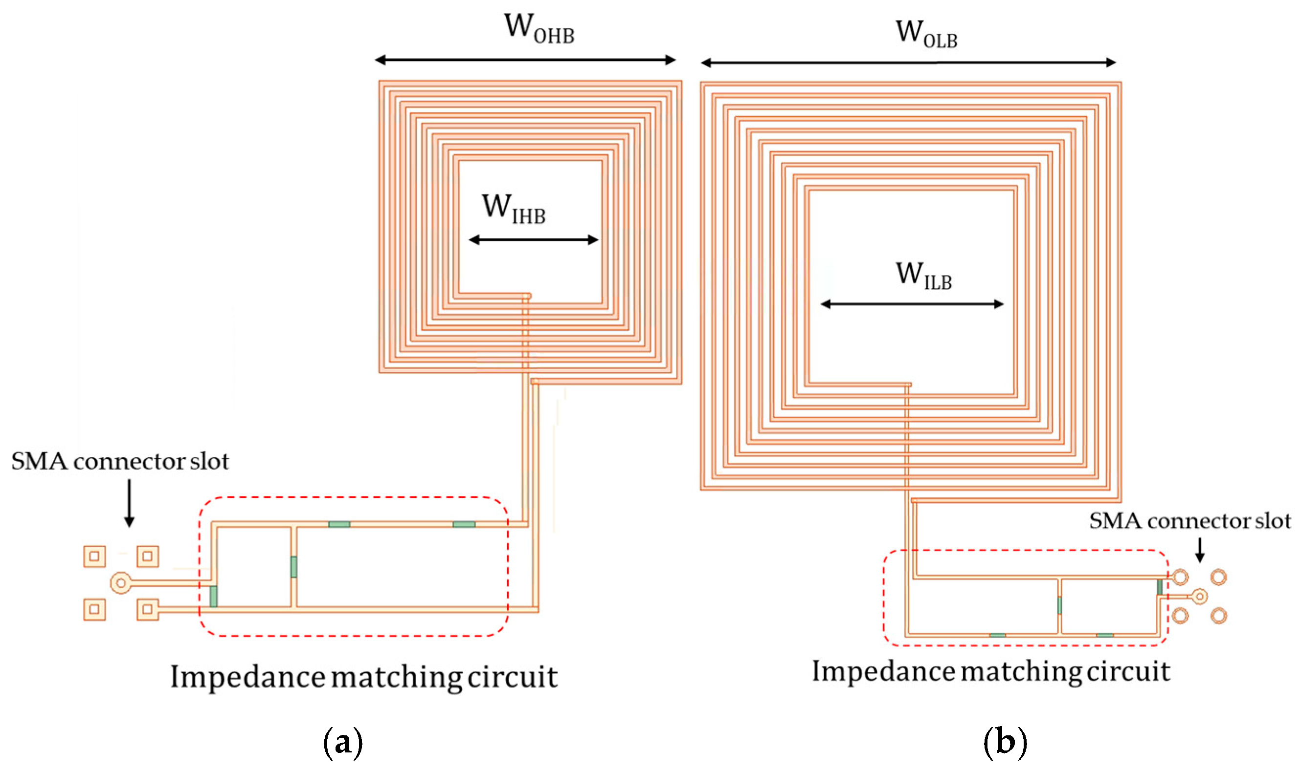
The MR-WPT coupler proposed in this study is presented in Figure 3. Figure 3a depicts the HB MR-WPT coupler designed to operate in the 13.56 MHz band, while Figure 3b shows the LB MR-WPT coupler designed for operation in the 6.78 MHz band. The specifications of these couplers are summarized in Table 2.
The HB MR-WPT and LB MR-WPT couplers are arranged in a stacked configuration to facilitate the analysis of transmission characteristics and interference. Specifically, a pair of LB MR-WPT couplers are positioned facing each other at the outer layers, with a pair of HB MR-WPT couplers stacked between them at the inner layers in a facing orientation. An impedance matching circuit is incorporated to achieve resonance at 6.78 MHz and 13.56 MHz. The circuit is implemented by extending the copper sheet, on which the coils are designed, to form conductors. The coils are fabricated on a Taconic RF-35™ substrate, which includes a dielectric layer. Furthermore, as the HB MR-WPT coupler is positioned between the LB MR-WPT couplers, a ferrite sheet is attached to its bottom to mitigate magnetic field influences. The copper sheet has a thickness of 0.035 mm, and the dielectric loss tangent is 0.0018. ANSYS HFSS 2021 R2 (Canonsburg, PA, USA) was employed for the simulations.
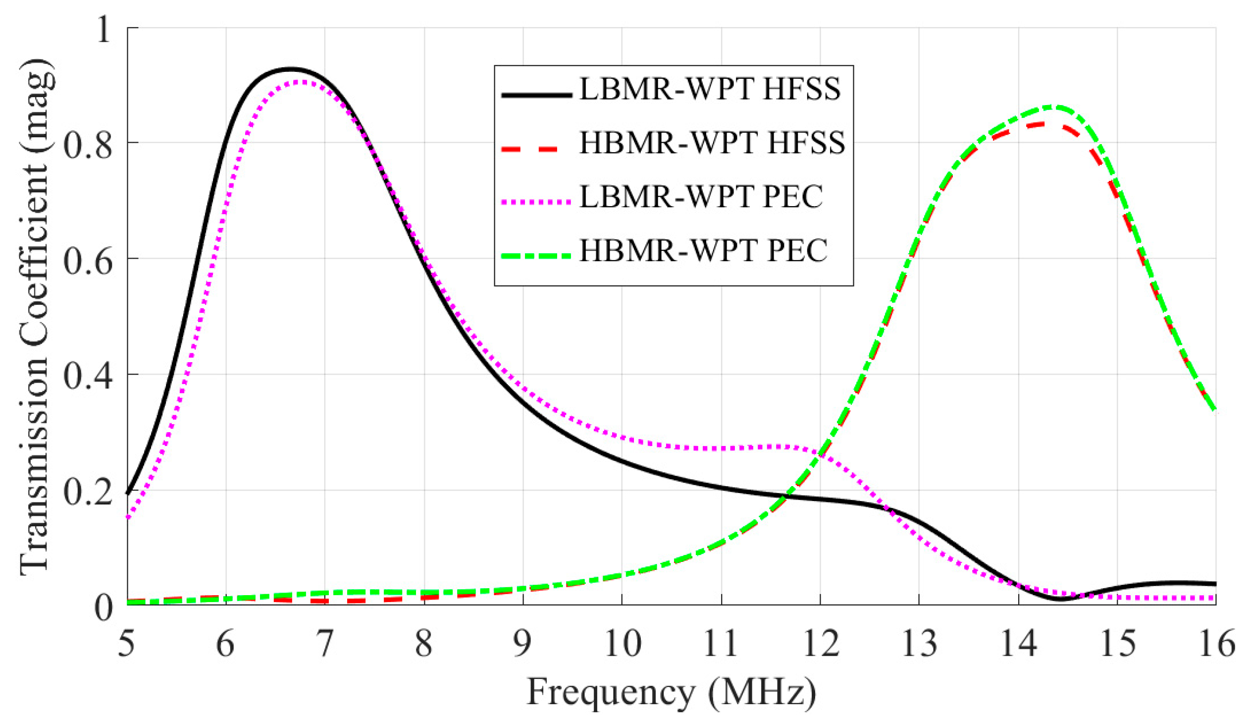
The transmission coefficients in Figure 4, obtained by fitting PEC to HFSS under ideal matching conditions, exhibit close agreement between PEC and HFSS for both LBMR-WPT and HBMR-WPT main coupling, confirming the model’s capability to replicate idealized simulation outcomes with high precision at resonance frequencies. This fitting verifies the baseline accuracy of PEC before incorporating empirical losses, laying the foundation for subsequent comparisons with measurements.
Table 3 summarizes the parameters derived from the PEC model fitted to the HFSS model. Here, the coupling coefficient can generally be expressed as in Equation (6). In the PEC model proposed in this study, the T-model incorporating mutual coupling is represented by a total of six subcircuits. Each port is connected to the other ports through three T-model networks, illustrating the circuit interconnections. Therefore, it cannot be defined using the conventional coupling coefficient formula. The values in the table for the equivalent parameters are derived for computation within the PEC and do not involve calculating k from a two-port perspective. For each T-model network, the self-inductance is defined as the inherent inductance minus the mutual inductance in accordance with standard T-model conventions, resulting in three distributed self-inductances per port due to the branching into three networks; consequently, the coupling coefficient is approximated by summing the mutual inductances across these networks, as shown in Equation (7).
k M N = M MN L MM · L NN
k MN M MN ( L MM + M MN ) · ( L NN + M MN )
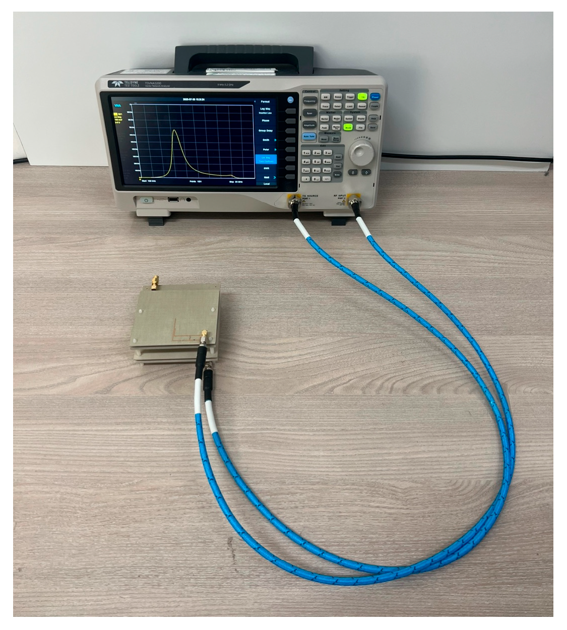
Based on this electromagnetic simulation model, a physical prototype was fabricated using Taconic RF35 substrate. Figure 5a,b present the front and back views of the LB MR-WPT coupler, respectively, whereas Figure 5c,d display the front and back views of the HB MR-WPT coupler. Measurements were conducted using the vector network analyzer (T3VNA3200, Teledyne LeCroy, Chestnut Ridge, NY, USA), as shown in Figure 6. The experimentally extracted equivalent parameters are listed in Table 3. The absence of obstructions in the transmission path results in relatively high transmission coefficients. The accuracy of the proposed PEC model is verified by comparing it with HFSS simulations and measurement results.
Although the coupler is a 4-port structure, the measurements were performed using a 2-port VNA configuration. At each measurement, two ports were connected to the VNA while the remaining two ports were terminated with 50 Ω loads, thereby incorporating the effect of terminated ports into the observed S-parameters. Four representative measurement cases were conducted (LBMR-WPT Tx–Rx, HBMR-WPT Tx–Rx, LBMR-WPT Tx–HBMR-WPT Tx and LBMR-WPT Tx–HBMR-WPT Rx), which sufficiently cover all coupling scenarios of the 4-port system. This procedure ensures that both intra-band and cross-band transmission characteristics are captured, including potential interference paths.

2.2. Loss Prediction and Interference Analysis

Although loss and efficiency can be evaluated by direct power measurements, this work focuses on the coupler. Therefore, Equations (8)–(12) are written in terms of S-parameters so that loss, efficiency, and cross-band leakage can be predicted consistently across equivalent circuit analysis, HFSS, and measurements.
The power loss (PLoss) in the 4-port dual-band MR-WPT coupler is first introduced in Equation (8) as the ohmic dissipation and cross coupling loss. For practical evaluation, this relation can be reformulated in terms of S-parameters. Equation (9) expresses the total power loss based on S-parameters obtained from the equivalent circuit model, HFSS, or measurements. In this formulation, the input power is partitioned into reflection and transmission terms at each port, and the remaining term is interpreted as dissipated loss in the coils and coupling paths. This unified representation provides a consistent way to compare theoretical, simulated, and experimental results.
P L o s s = I 2 R + P C r o s s
P L o s s = P i n p u t × ( 1 | S 11 | 2 | S 21 | 2 | S 31 | 2 | S 41 | 2 )
Equation (10) defines the efficiency η of the MR-WPT coupler as the ratio of the transmitted power in the main coupling path to the absorbed input power, i.e., after excluding reflection at the input port. This enables direct comparison of intra-band transmission efficiency and cross-band leakage across all three analysis methods. Furthermore, interference is defined as the leakage power calculated for cross-band transmission paths, as described in Equation (11) and simplified in Equation (12). Together, these equations allow for a comprehensive evaluation of loss, efficiency, and interference, directly linking S-parameter analysis to the practical performance of the dual-band MR-WPT coupler.
η M R W P T = | S M N | 2 1 | S N N | 2
P l e a k = | S M N | 2 × P i n p u t
Interference   ( d B ) = 10 l o g 10 ( P l e a k P i n p u t )  
In this work, cross-band interference is defined as the unintended power leakage between the low-band (6.78 MHz) and high-band (13.56 MHz) channels, caused by mutual inductive coupling between coils operating at different resonance frequencies. Although not a universally standardized term in MR-WPT literature, it is explicitly adopted here to describe leakage effects that reduce system efficiency and may cause undesired interactions between dual-frequency channels. By quantifying this effect through the S-parameter based formulation in Equation (11) and (12), the proposed analysis enables consistent evaluation of cross-band leakage across the equivalent circuit model, HFSS, and measurements.

3. Results and Discussion

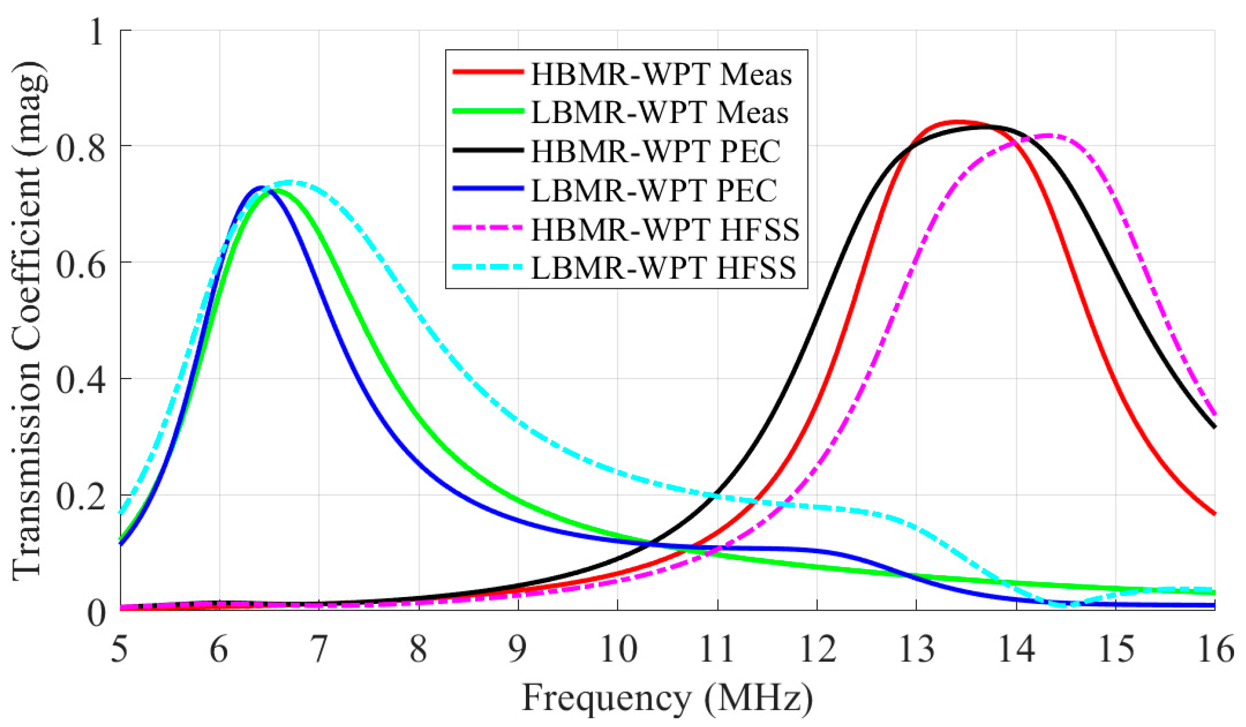
Analysis of the main coupling transmission coefficients in Figure 7 indicates consistent trends across PEC, HFSS, and measurement methods for both HBMR-WPT and LBMR-WPT, with PEC exhibiting the highest fidelity to measurements in all six plots, while HFSS shows slight deviations attributable to idealized modeling assumptions. The PEC model’s high fidelity is evident in peak transmission values and bandwidths, suggesting effective incorporation of real losses, whereas HFSS overestimates transmission at resonances due to absence of empirical damping; for instance, in HBMR-WPT, PEC tracks measurement curves with deviations below 5% near 13.56 MHz, underscoring its superior representation of practical coupling dynamics.
Parameters from PEC fitted to HFSS (idealized) are listed in Table 4, providing baseline values such as LHB = 2.7 μH and kHB = 0.66, whereas Table 4 details modifications after measurement fitting, including elevated resistances (e.g., RHB from 1.2 Ω to 5.5 Ω) and adjusted mutual inductances (e.g., MHB from 1.8 μH to 4 μH), reflecting the incorporation of empirical losses. These changes highlight how fitting accounts for fabrication variations and material imperfections, improving model accuracy over idealized HFSS simulations, as evidenced by the increased cross-coupling coefficients that better capture real-world interactions between bands.
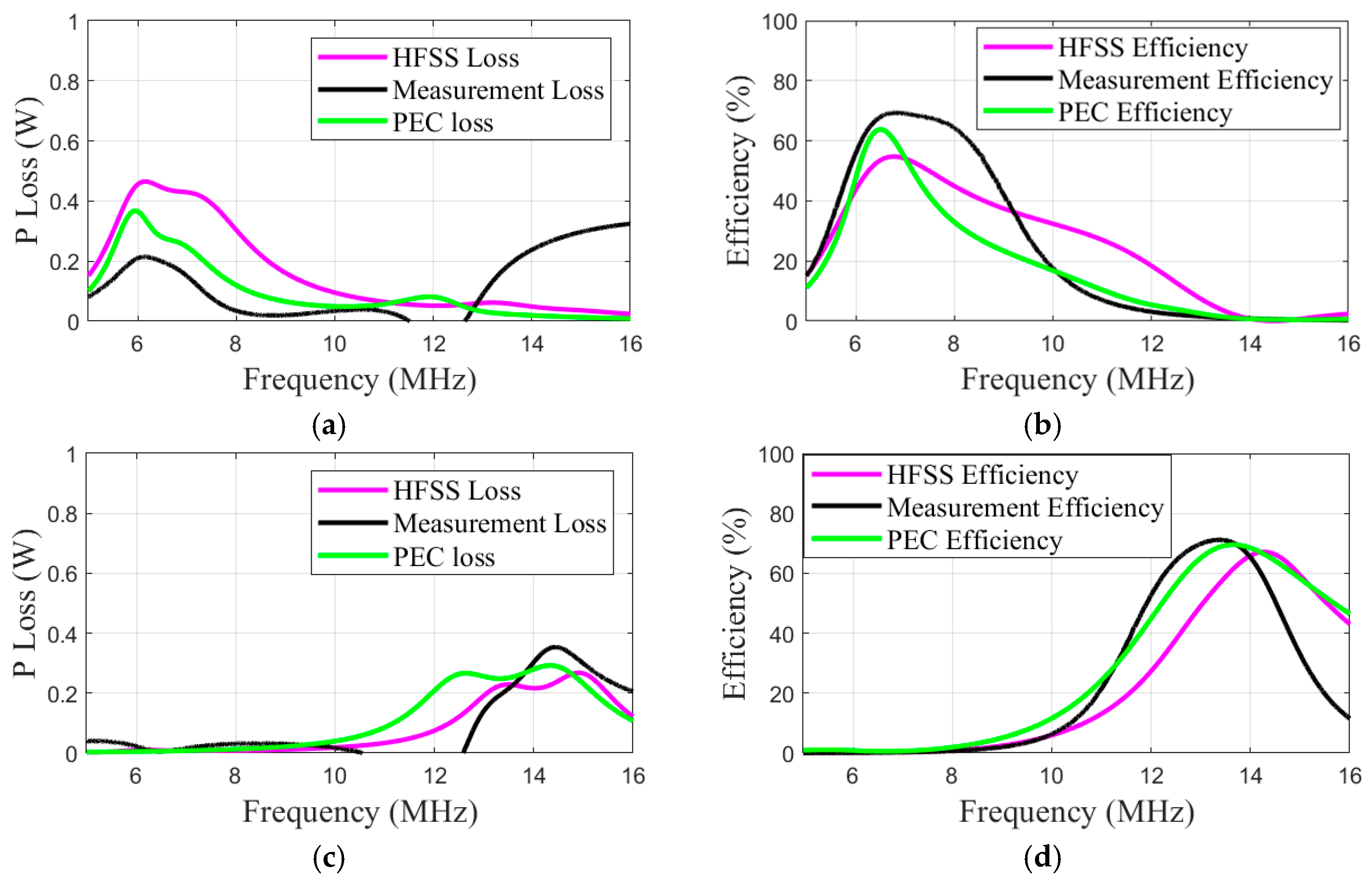
Power loss and efficiency comparisons in Figure 8 indicate that for the LB MR-WPT, HFSS simulations yield the highest losses and lowest efficiencies, measurements exhibit the lowest losses and highest efficiencies, and the PEC model provides an intermediate profile with high fidelity to the measurements (panels a and b). For the HB MR-WPT, the loss trends are similar across models, although measurements show PLoss approaching zero in the 10–13 MHz range due to S-parameter anomalies, with efficiencies aligning most closely between the PEC model and measurements (panels c and d). Notably, the PEC model’s loss curves exhibit smoother transitions near resonance frequencies, demonstrating robust handling of cross-band effects. Furthermore, the efficiency maxima summarized in Table 5 confirm the PEC model’s close agreement with measurement data (e.g., 69.52% for HB MR-WPT in PEC vs. 71.18% in measurements), underscoring its capability to balance theoretical precision with empirical realism across the frequency spectrum.
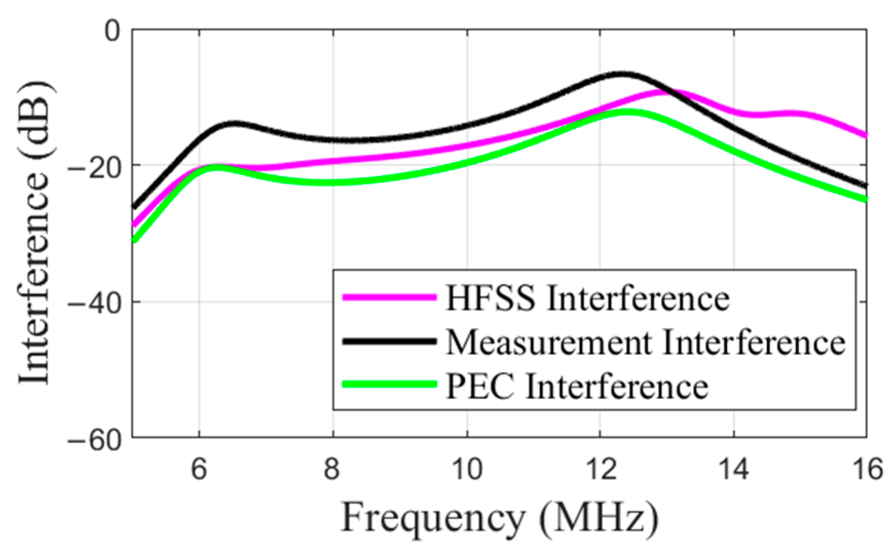
Cross-band interference levels in Figure 9 show uniform trends across methods, indicating stable low leakage (e.g., −20 to −60 dB), which can be interpreted as minimal cross-coupling impact at resonances, supporting PEC’s realistic estimates for dual-band operation. The graph’s convergence at off-resonance frequencies suggests negligible interference beyond operational bands, reinforcing the system’s suitability for biomedical applications where signal isolation is critical; PEC’s interference values remain within 3 dB of measurements, affirming its predictive power for scenarios involving potential tissue-induced variations.
The observed fidelity of PEC to measurements in Figure 7 and Table 2 and Table 3 underscores the model’s capacity to capture real-world losses through parameter adjustments, such as increased resistances and mutual inductances, thereby surpassing HFSS idealized simulations in representing structural effects within dual-band MR-WPT systems. In Figure 8, the intermediate positioning of PEC in LBMR-WPT loss and near-maximal efficiency alignment affirm its role in mediating between theoretical and practical outcomes. However, PLoss anomalies in HBMR-WPT point to potential S-parameter calculation artifacts requiring calibration. The consistent interference trends in Figure 9, with levels below −20 dB at peaks, indicate minimal cross-coupling impact. This correlates with efficiency reductions and supports coil detuning as a mitigation strategy for biomedical contexts. Limitations encompass dependence on single-case data, constraining generalizability, and absence of direct tissue validation; future studies might incorporate multi-case measurements and phantom models to enhance biomedical relevance.

4. Conclusions

This study validates the PEC model for analyzing cross-band interference and losses in compact dual-frequency 4-port inductive couplers. The model achieves high fidelity to measurements through fitting to HFSS idealized simulations and empirical data. The findings include consistent transmission coefficients across methods, adjusted parameters that reflect real losses (e.g., elevated resistances and mutual inductances), and quantified metrics that demonstrate PEC’s intermediate power loss profiles, near-maximal efficiencies, and stable low interference levels below −20 dB. These results affirm the model’s ability to bridge theoretical and practical performance in dual-band MR-WPT systems suited for wearable biomedical applications. The fitted loss resistances link to tissue-induced effects, and the model thus provides insights into efficiency variations during skin penetration. This linkage enables predictions without further experiments. Future work may extend this approach to multi-case validations and incorporate tissue phantoms to bolster its utility in biomedical device design.

Author Contributions

Conceptualization, S.-W.P. and H.-G.B.; methodology, S.-W.P.; software, H.-G.B.; validation, H.-G.B.; formal analysis, H.-G.B.; investigation, H.-G.B.; resources, S.-W.P.; data curation, H.-G.B.; writing—original draft preparation, H.-G.B.; writing—review and editing, H.-G.B.; visualization, H.-G.B.; supervision, S.-W.P.; project administration, S.-W.P.; funding acquisition, S.-W.P. All authors have read and agreed to the published version of the manuscript.

Funding

This work was supported by the Soonchunhyang University Research Fund.

Data Availability Statement

The raw data supporting the conclusions of this article will be made available by the authors upon request.

Conflicts of Interest

The authors declare no conflicts of interest.

References

  1. Marangalou, A.H.; Gonzalez, M.; Reppucci, N.; Guler, U. A Design Review for Biomedical Wireless Power Transfer Systems with a Three-Coil Inductive Link through a Case Study for NICU Applications. Electronics 2024, 13, 3947. [Google Scholar] [CrossRef]
  2. Khan, S.R.; Pavuluri, S.K.; Cummins, G.; Desmulliez, M.P.Y. Wireless Power Transfer Techniques for Implantable Medical Devices: A Review. Sensors 2020, 20, 3487. [Google Scholar] [CrossRef] [PubMed]
  3. Alrashdan, F.T.; Chen, J.C.; Singer, A.; Avants, B.W.; Yang, K.; Robinson, J.T. Wearable Wireless Power Systems for ‘ME-BIT’ Magnetoelectric-Powered Bio Implants. J. Neural Eng. 2021, 18, 045011. [Google Scholar] [CrossRef] [PubMed]
  4. Gong, C.; Liu, D.; Miao, Z.; Wang, W.; Li, M. An NFC on Two-Coil WPT Link for Implantable Biomedical Sensors under Ultra-Weak Coupling. Sensors 2017, 17, 1358. [Google Scholar] [CrossRef] [PubMed]
  5. Shah, I.A.; Zada, M.; Basir, A.; Shah, S.A.A.; Iman, U.R.; Lim, Y.-H.; Yoo, H. Efficient Wirelessly Powered Biotelemetric System for IoMT-Enabled Leadless Pacemakers in Dynamic Cardiac Environments. IEEE Internet Things J. 2025, 12, 6917–6929. [Google Scholar] [CrossRef]
  6. Ben Ammar, M.; Ben Dhaou, I.; El Houssaini, D.; Sahnoun, S.; Fakhfakh, A.; Kanoun, O. Requirements for Energy-Harvesting-Driven Edge Devices Using Task-Offloading Approaches. Electronics 2022, 11, 383. [Google Scholar] [CrossRef]
  7. Abbas, N.; Basir, A.; Ali Shah, I.; Rizqi Iman, U.; Yoo, H. Development of an Efficient Mid-Field Wireless Power Transmission System for Biotelemetric IoT Medical Devices. Sci. Rep. 2025, 15, 14889. [Google Scholar] [CrossRef]
  8. RamRakhyani, A.K.; Lazzi, G. Multi-coil Approach to Reduce Electromagnetic Energy Absorption for Wirelessly Powered Implants. Healthc. Tech. Lett. 2014, 1, 21–25. [Google Scholar] [CrossRef]
  9. Awuah, C.M.; Danuor, P.; Moon, J.-I.; Jung, Y.-B. Novel Coil Design and Analysis for High-Power Wireless Power Transfer with Enhanced Q-Factor. Sci. Rep. 2023, 13, 4187. [Google Scholar] [CrossRef]
  10. Yoon, S.; Lim, T.; Lee, Y. Multifunctional coil technique for alignment-agnostic and Rx coil size-insensitive efficiency enhancement for wireless power transfer applications. Sci. Rep. 2023, 13, 22838. [Google Scholar] [CrossRef]
  11. Yadav, A.; Bera, T.K. A Critical Review of Electromagnetic Coil Assembly Design and Optimization for Wireless Power Transfer in Electric Vehicles: Technical Insights. Renew. Sustain. Energy Rev. 2025, 223, 115944. [Google Scholar] [CrossRef]
  12. Machnoor, M.; Gamez Rodriguez, E.S.; Kosta, P.; Stang, J.; Lazzi, G. Analysis and Design of a 3-Coil Wireless Power Transmission System for Biomedical Applications. IEEE Trans. Antennas Propag. 2019, 67, 5012–5024. [Google Scholar] [CrossRef]
  13. Alghrairi, M.; Sulaiman, N.; Mutashar, S.; Hasan, W.Z.W.; Jaafar, H.; Algriree, W. Designing and Analyzing Multi-Coil Multi-Layers for Wireless Power Transmission in Stent Restenosis Coronary Artery. AIP Adv. 2022, 12, 125315. [Google Scholar] [CrossRef]
  14. Kung, M.-L.; Lin, K.-H. Dual-Band Coil Module With Repeaters for Diverse Wireless Power Transfer Applications. IEEE Trans. Microw. Theory Tech. 2018, 66, 332–345. [Google Scholar] [CrossRef]
  15. Le-Huu, H.; Seo, C. Dual-Band Free-Positioning Transmitting Coil for Multiple-Receiver Wireless Power Transfer. IEEE Access 2021, 9, 107298–107308. [Google Scholar] [CrossRef]
  16. Iqbal, A.; Sura, P.R.; Al-Hasan, M.; Mabrouk, I.B.; Denidni, T.A. Wireless Power Transfer System for Deep-Implanted Biomedical Devices. Sci. Rep. 2022, 12, 13689. [Google Scholar] [CrossRef]
  17. Ojha, S.S.; Singhal, P.K.; Thakare, V.V. Dual-Band Rectenna System for Biomedical Wireless Applications. Meas. Sens. 2022, 24, 100532. [Google Scholar] [CrossRef]
  18. Mahmud, S.; Nezaratizadeh, A.; Satriya, A.B.; Yoon, Y.-K.; Ho, J.S.; Khalifa, A. Harnessing Metamaterials for Efficient Wireless Power Transfer for Implantable Medical Devices. Bioelectron. Med. 2024, 10, 7. [Google Scholar] [CrossRef] [PubMed]
  19. Le-Huu, H.; Seo, C. Dual-Band Transmitter for Wireless Power Transfer to Biomedical Implant Applications. Antennas Wirel. Propag. Lett. 2023, 22, 1461–1465. [Google Scholar] [CrossRef]
  20. Byron, K.; Winkler, S.A.; Robb, F.; Vasanawala, S.; Pauly, J.; Scott, G. An MRI Compatible RF MEMs Controlled Wireless Power Transfer System. IEEE Trans. Microw. Theory Tech. 2019, 67, 1717–1726. [Google Scholar] [CrossRef]
  21. Martins, I.S.; Silva, H.F.; Lazareva, E.N.; Chernomyrdin, N.V.; Zaytsev, K.I.; Oliveira, L.M.; Tuchin, V.V. Measurement of Tissue Optical Properties in a Wide Spectral Range: A Review [Invited]. Biomed. Opt. Express 2023, 14, 249. [Google Scholar] [CrossRef] [PubMed]
  22. Bae, H.; Park, S. Design of an Integrated Near-Field Communication and Wireless Power Transf. Coupler for Mobile Device Applications. Technologies 2025, 13, 207. [Google Scholar] [CrossRef]
  23. Bae, H.; Park, S. Design of Four-Plate Parallel Dynamic Capacitive Wireless Power Transfer Coupler for Mobile Robot Wireless-Charging Applications. Appl. Sci. 2025, 15, 823. [Google Scholar] [CrossRef]
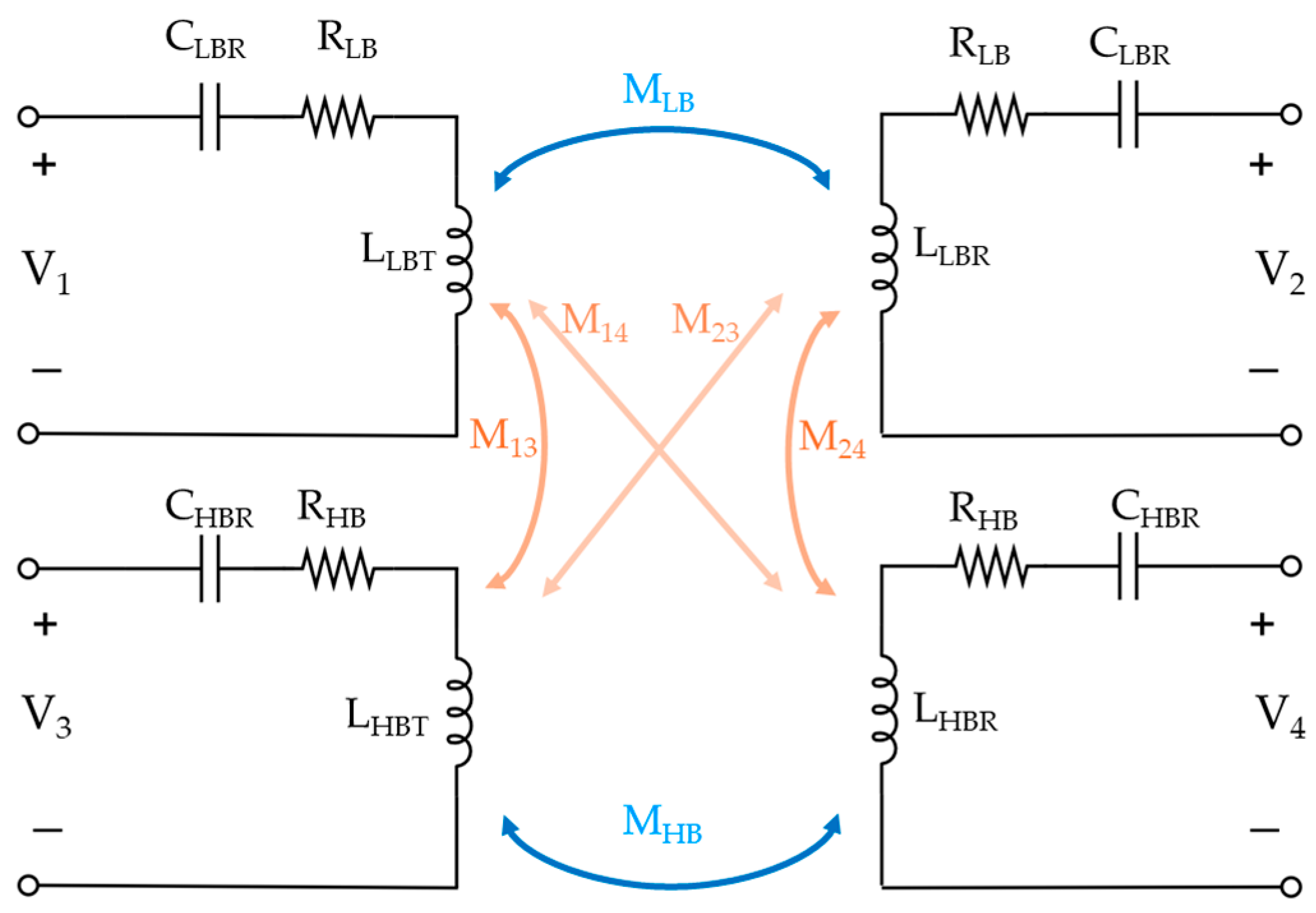
Figure 1. Mutual coupling of 4-port MR-WPT coupler.
Electronics 14 03637 g001
Figure 2. PEC of MR-WPT coupler.
Electronics 14 03637 g002
Figure 3. Configuration of MR-WPT couplers: (a) HBMR-WPT coupler; (b) LBMR-WPT.
Electronics 14 03637 g003
Figure 4. Transmission coefficients of MR-WPT using ideal matching.
Electronics 14 03637 g004
Figure 5. Fabricated models of MR-WPT coupler: (a) Top view of LBMR-WPT; (b) bottom view of LBMR-WPT; (c) top view of HBMR-WPT; (d) bottom view of HBMR-WPT.
Electronics 14 03637 g005
Figure 6. Experimental setup.
Electronics 14 03637 g006
Figure 7. Transmission coefficients of fitting for fabricated models.
Electronics 14 03637 g007
Figure 8. Comparison of P_Loss and Efficiency: (a) P_Loss from LBMR-WPT; (b) efficiency of LBMR-WPT; (c) P_Loss of HBMR-WPT; (d) efficiency of HBMR-WPT.
Electronics 14 03637 g008
Figure 9. Comparison of interference.
Electronics 14 03637 g009
Table 1. Corresponding circuit networks by PCN types.
TypesCorresponding Circuit Networks
[T]TypeA[T]HBT, [T]HBR
[T]TypeB[T]MHB, [T]MLB, [T]MTT, [T]MRR, [T]MHL
[T]TypeD[T]LBT, [T]LBR
Table 2. Extracted parameters from PEC, HFSS, and measurements.
ComponentsValue
LBMR-WPT coil outer width (WOLB)55 mm
LBMR-WPT coil inner width (WILB)27 mm
LBMR-WPT conductor line spacing1 mm
LBMR-WPT conductor line width0.5 mm
HBMR-WPT coil outer width (WOHB)29 mm
HBMR-WPT coil inner width (WIHB)13 mm
Ferrite side length32 mm
Distance between HB and LB MR-WPT coils (equal to RX)2 mm
Spacing between HBMR-WPT Tx and Rx15 mm
Substrate length100 mm
Substrate width84 mm
Table 3. Extracted parameters from PEC and HFSS.
NotationComponentsValue
LHBSelf-inductance of the HB MR-WPT coupler2.7 μH
LLBSelf-inductance of the LB MR-WPT coupler5.95 μH
RHBResistance of the HB MR-WPT coupler1.2 Ω
RLBResistance of the LB MR-WPT coupler2.7 Ω
MHBMutual inductance between Tx and Rx in the HBMR-WPT1.8 μH
MLBMutual inductance between Tx and Rx in the LBMR-WPT2.25 μH
MHLCross mutual inductance between Tx and Rx0.4 μH
MTX, MRXCross mutual inductance between Tx or Rx1.2 μH
kHBCoupling coefficient within the HBMR-WPT0.66
kLBCoupling coefficient within the LBMR-WPT0.25
kHLCross coupling coefficient between HB and LB MR-WPT0.23
Table 4. Extracted parameters from PEC-fitted measurement models.
NotationComponentsValue
LHBSelf-inductance of the HB MR-WPT coupler2.7 μH
LLBSelf-inductance of the LB MR-WPT coupler5.95 μH
RHBResistance of the HB MR-WPT coupler5.5 Ω
RLBResistance of the LB MR-WPT coupler1.2 Ω
MHBMutual inductance between Tx and Rx in the HBMR-WPT4 μH
MLBMutual inductance between Tx and Rx in the LBMR-WPT4.2 μH
MHLCross mutual inductance between Tx and Rx4.4 μH
MTX, MRXCross mutual inductance between Tx or Rx4 μH
kHBCoupling coefficient within the HBMR-WPT0.6
kLBCoupling coefficient within the LBMR-WPT0.42
kHLCross coupling coefficient between HB and LB MR-WPT0.5
Table 5. Table comparing method, max loss, and max efficiency.
MethodMax Loss (W)Max Efficiency (%)
LBMR-WPTHBMR-WPTLBMR-WPTHBMR-WPT
HFSS0.470.2754.7667.13
PEC0.370.2963.4969.52
Measurement0.220.3569.3371.18
Disclaimer/Publisher’s Note: The statements, opinions and data contained in all publications are solely those of the individual author(s) and contributor(s) and not of MDPI and/or the editor(s). MDPI and/or the editor(s) disclaim responsibility for any injury to people or property resulting from any ideas, methods, instructions or products referred to in the content.