Article

Enhancing Multiple-Access Capacity and Synchronization in Satellite Beam Hopping with NOMA-SIC

by
Tengfei Hui
1,2,
Shenghua Zhai
2,*,
Mingming Hui
2,
Fengkui Gong
1,
Ruyan Lin
3 and
Yulong Fu
3
1
School of Communication Engineering, Xidian University, Xi’an 710126, China
2
CAST (China Academy of Space Technology), Xi’an Institute of Space Radio Technology, Xi’an 710010, China
3
School of Cyber Engineering, Xidian University, Xi'an 710126, China
*
Author to whom correspondence should be addressed.
Electronics 2025, 14(18), 3578; https://doi.org/10.3390/electronics14183578
Submission received: 7 August 2025 / Revised: 31 August 2025 / Accepted: 8 September 2025 / Published: 9 September 2025

Abstract

Enhancing user access capacity in satellite beam-hopping systems remains challenging due to dynamic traffic and limited beam dwell times. Conventional Multi-Frequency Time-Division Multiple Access (MF-TDMA) proves highly inefficient under such constraints. To overcome this, we propose a novel scheme that integrates power-domain Non-Orthogonal Multiple Access (NOMA) with MF-TDMA, employing Successive Interference Cancelation (SIC) for multi-user signal separation. A bi-directional adaptive carrier synchronization method and optimized burst structure are introduced, which collectively reduce synchronization overhead by over 40% compared to MF-TDMA. Simulations demonstrate a dramatically improved frame error rate of 0.0005% at 4 dB SNR—30 times lower than the 0.016% achieved by MF-TDMA—and a transmission efficiency of 92–97%, significantly outperforming conventional MF-TDMA. These results validate the proposed method’s substantial gains in capacity and efficiency for next-generation satellite systems.

1. Introduction

With the rapid growth in global demand for high-capacity satellite communications, operators of both Low Earth Orbit (LEO) and Geostationary Earth Orbit (GEO) systems have widely adopted beam-hopping technology to achieve more dynamic and flexible resource allocation [1,2,3]. Unlike traditional fixed-beam coverage, beam hopping uses a time-division strategy, dynamically switching beams across different service areas within the satellite footprint according to predefined patterns, enabling on-demand coverage. This technology can range from fixed beam-pointing to fully steerable systems, allowing high-traffic areas to be allocated more beam time slots, while low-traffic regions receive fewer, thus improving overall system efficiency [4]. When combined with onboard regenerative processing (such as demodulation and IP routing) and inter-satellite link (ISL)-based data transmission, these systems can provide wideband global coverage and enhanced interconnectivity among terminals and services. Furthermore, this approach reduces reliance on large-scale ground infrastructure, making IP-based onboard processing architecture a critical direction for the future development of broadband satellite networks.
However, the widespread adoption of beam-hopping technology introduces several pressing challenges. First, a sharp conflict has emerged between the surge in user numbers and the scarcity of spectrum resources. Second, the inherently short beam dwell times (typically less than 10 ms) place a significant burden on multiple access schemes. Within each beam’s dwell slot, a large number of users share limited resources. Consequently, how to effectively enhance user access capacity and spectrum efficiency under these constraints has become a central issue in the design of next-generation satellite communication systems.
Currently, satellite communication systems predominantly rely on traditional orthogonal multiple access (OMA) techniques, such as Multi-Frequency Time-Division Multiple Access (MF-TDMA), to allocate resources to users through fixed frequency-time slots. This method provides each user with an orthogonal, interference-free channel and serves as a benchmark scheme in both industry and academia for multi-user scenarios, as reflected in standards such as DVB-S2X [5].
Although MF-TDMA is effective under static and low-traffic conditions, it faces considerable efficiency limitations in dynamic and bursty traffic environments. Its inherent rigid resource partitioning cannot efficiently accommodate the growing number of users and fluctuating traffic demands, and the short beam dwell time (typical parameters range from microseconds to milliseconds). For example, the RSM-A standard provides a downlink beam hopping allocation with a time granularity of 22 µs, leading to frequent resource reallocations and high scheduling overhead, ultimately reducing overall system capacity and throughput [6]. On the other hand, Non-Orthogonal Multiple Access (NOMA), a promising candidate for improving spectrum efficiency in terrestrial communications [7,8,9], faces its own set of challenges when applied to satellite systems. Satellite links typically operate in low Signal-to-Noise Ratio (SNR) environments, where the core NOMA technique of Successive Interference Cancelation (SIC) is highly sensitive to phase and synchronization errors, which can severely degrade decoding performance [10]. Furthermore, existing NOMA schemes typically require long preambles (often over 100 symbols) to ensure synchronization, leading to significant overhead and reducing transmission efficiency [11]. There is also a lack of theoretical models, particularly closed-form Bit Error Rate (BER) expressions, for multi-signal SIC reception under satellite beam-hopping conditions [9].
To overcome the capacity bottleneck of MF-TDMA and the technical challenges of NOMA in satellite applications, this paper proposes an innovative enhanced beam-hopping multiple access framework that deeply integrates NOMA with SIC. By introducing power-domain multiplexing into the traditional MF-TDMA time-frequency grid, this framework allows signals from multiple users to be superimposed on the same time-frequency resource and subsequently separated at the receiver via SIC. This scheme aims to significantly increase multiple access capacity and spectral efficiency without requiring additional bandwidth, while also ensuring robust synchronization in the complex satellite communication environment. A comparison as in Table 1 between MF-TDMA and NOMA-SIC has been shown, summarizing their differences in spectral efficiency, latency, and complexity.
The core scientific challenges addressed in this work are (1) overcoming the degradation of SIC performance under low-SNR satellite channels, where interference and weak signal conditions can significantly impair decoding accuracy, reducing overall system efficiency; (2) achieving reliable synchronization within ultra-short beam dwell times (typically <10 ms), which is critical for accurate time alignment in fast beam-hopping scenarios, ensuring efficient use of resources; and (3) establishing theoretical BER models for multi-signal NOMA-SIC reception in satellite systems, where existing models are lacking due to the complex dynamics of satellite communication and beam-hopping. These challenges are key to improving spectrum efficiency and throughput in next-generation satellite communication systems, and this work provides innovative solutions to address each of them.
The main contributions of this paper can be summarized as follows:
  • We propose an enhanced NOMA-SIC multiple access framework for the satellite beam-hopping context, which addresses the capacity limitations of traditional MF-TDMA.
  • We derive closed-form theoretical expressions for the BER of SIC reception, which fills a critical gap in the performance analysis for multi-signal satellite systems.
  • We design a novel carrier synchronization scheme that combines a preset frequency offset with bi-directional adaptive iteration, which solves the challenge of robust synchronization under low SNR and strong interference.
  • We optimize a high-efficiency dual unique word (UW) burst frame structure that complements our synchronization scheme, which significantly reduces overhead and increases transmission efficiency to 97%.
The remainder of the paper is structured as follows: Section 2 presents the theoretical derivation of BER for multi-signal SIC reception. Section 3 discusses the challenges in carrier synchronization and introduces the joint frequency-synchronization scheme. Section 4 demonstrates the performance gains through simulations. Finally, conclusions are drawn in Section 5

2. System Model and Theoretical Analysis

In this section, we describe the system model used in the proposed beam-hopping architecture and provide a theoretical analysis of the BER performance for multi-signal reception. Unlike traditional fixed-beam coverage, where beams cover predetermined, static areas, beam-hopping adopts a time-division strategy, dynamically switching beams across different regions of the satellite footprint according to predefined patterns. This enables flexible, on-demand coverage, allocating more beam time slots to high-traffic areas and fewer to regions with lower demand, thereby optimizing resource allocation and enhancing overall system efficiency. The implementation of beam-hopping systems can vary from simple fixed beam-pointing to more advanced, fully steerable systems, as illustrated in Figure 1.
The flexibility of beam-hopping technology is particularly advantageous in satellite communication systems, as it allows for better adaptation to dynamic traffic demands and minimizes congestion in heavily used areas. Moreover, when combined with onboard regenerative processing capabilities—such as demodulation, IP routing, and ISLs for data transmission—beam-hopping systems can provide wideband global coverage. This architecture also facilitates greater interconnectivity among diverse terminals and services, reducing the dependency on large-scale ground infrastructure. As shown in Figure 2, the proposed IP-based onboard processing architecture significantly enhances the performance and scalability of broadband satellite networks by integrating both data routing and processing onboard the satellite, leading to a more efficient use of available bandwidth and a reduction in latency.

2.1. Principle of SIC

NOMA is a key technology for improving spectral efficiency and user capacity in communication systems. Its core principle involves non-orthogonal signal transmission at the transmitter, which intentionally introduces inter-user interference by sharing time-frequency resources. This interference is then resolved at the receiver using SIC, enabling correct recovery of all user signals—effectively trading receiver complexity for greater spectral efficiency.
The basic operation of SIC involves sequentially detecting and decoding superimposed signals based on their received power levels. The strongest signal is decoded first, subtracted from the composite signal, and the process repeats in descending power order until all signals are recovered. For K superimposed signals, K levels of serial processing are required. This power-based decoding order ensures sufficient SNR for reliable detection, hence the name Successive Interference Cancelation.
The basic architecture of a SIC-based receiver is illustrated in Figure 3. The receiver first demodulates the strongest signal using conventional demodulation techniques. Then, it reconstructs the estimated signal S 1 t  based on its amplitude and removes it from the composite signal to generate a new mixture r 2 t  for the next decoding stage.
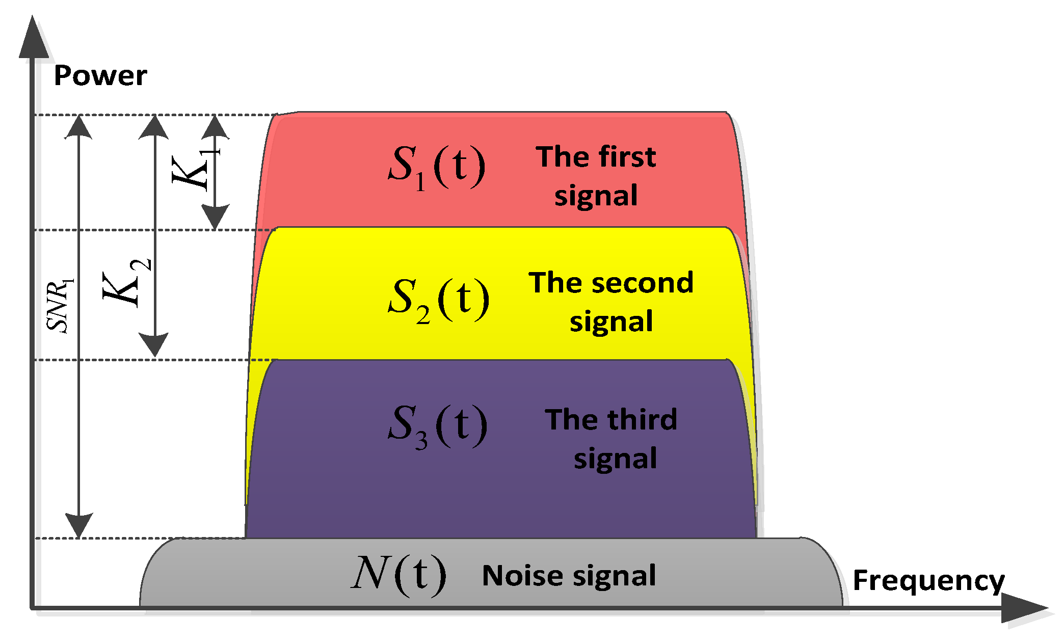
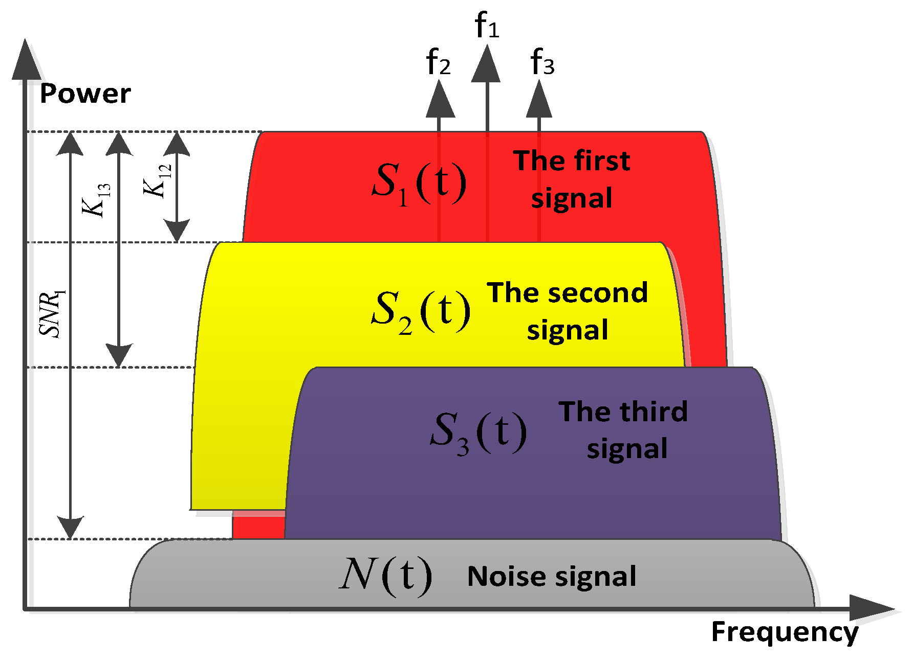
Figure 4 illustrates the NOMA-based multiple access method applied to the uplink of a beam-hopping system, with a total of three superimposed user signals. In this scheme, multiple users are allocated the same time slot and frequency resource, thereby enhancing system capacity. The receiver employs SIC techniques to separate and decode individual user signals. It should be emphasized that during resource allocation, all users occupy identical frequency bands and time durations.
In conclusion, in SIC-based uplink capacity enhancement schemes, system design must consider not only the conventional SNR but also the power disparity between multiple superimposed signals. A smaller power gap reduces the dynamic range requirement of the terminal and onboard receivers. However, this imposes additional challenges on the receiver’s signal separation and decoding capability. Hence, parameter optimization is essential for system design. The following section provides a theoretical performance analysis of multi-signal reception based on the SIC technique.

2.2. Theoretical Performance Analysis for Two Overlapping Signals

Consider a synchronized TDMA system with K simultaneously active users transmitting on the same frequency. Over an additive white Gaussian noise (AWGN) channel, the received signal can be expressed as:
r ( n ) = m = 1 K A m S m ( n ) + σ N ( n ) ,
where
  • A m : amplitude of the m t h  user signal;
  • S m n : transmitted BPSK signal, taking values in ±1;
  • σ N n : AWGN with power spectral density σ 2 .
For a two-user superposition scenario, the received signal simplifies to
r ( n ) = A 1 S 1 ( n ) + A 2 S 2 ( n ) + σ N ( n ) .
Assume the following:
  • A 1 S 1 n : stronger signal;
  • A 2 S 2 n : weaker signal.
Define the power ratio as follows:
K 1 = 10 1 g   ( A 1 2 A 2 2 ) .
Let the amplitude ratio be W 1 = A 1 A 2 . Then, A 2 = A 1 W 1 , and W 1 = 10 K 1 20 .
The bit error performance of S 1  is affected by both thermal noise and interference from S 2 , especially when the polarity of S 2  opposes S 1 . The most critical condition occurs when the two signals are out-of-phase with maximum relative amplitude.
Let us define the following probabilities for the transmission and detection of signals in the system:
  • P 1 S 1 : Probability that the first signal S 1  transmitted symbol is 1, which is 1/2.
  • P 1 S 1 : Probability that the first signal S 1  transmitted symbol is −1, which is 1/2.
  • P 1 S 2 : Probability that the second signal S 2  transmitted symbol is 1, which is 1/2.
  • P 1 S 2 : Probability that the second signal S 2  transmitted symbol is −1, which is 1/2.
  • P S 1 1 | 1 : Probability that the first signal S 1 , when transmitted as 1, is incorrectly detected as −1.
  • P S 1 1 | 1 : Probability that the first signal S 1 , when transmitted as -1, is incorrectly detected as 1.
  • P 1 , 1 S 1 S 2 1 | 1 , 1 : Probability that the first signal S 1 , when transmitted as 1 and the second signal S 2  as 1, is incorrectly detected as −1.
  • P 1 , 1 S 1 S 2 1 | 1 , 1 : Probability that the first signal S 1 , when transmitted as 1 and the second signal S 2  as -1, is incorrectly detected as -1.
  • P 1 , 1 S 1 S 2 1 | 1 , 1 : Probability that the first signal S 1 , when transmitted as -1 and the second signal S 2  as 1, is incorrectly detected as 1.
  • P 1 , 1 S 1 S 2 1 | 1 , 1 : Probability that the first signal S 1 , when transmitted as -1 and the second signal S 2  as -1, is incorrectly detected as 1.
The above applies for the following conditions:
  • S 1  and S 2  are the transmitted symbols for the first and second signals, respectively.
  • 1/−1 represents the detected symbol for the signal.
These probabilities are essential in analyzing the error performance of the system, particularly in multiple access schemes where interference between signals can affect detection accuracy.
Using BPSK error probability expressions and conditioning on the values of S 2 , the average BER for S 1  under SIC processing is
B E R B P S K = P 1 S 1 × P S 1 1 1 + P 1 S 1 × P S 1 1 1   = 1 2 × P S 1 1 1 + 1 2 × P S 1 1 1     .
P S 1 1 1 = P 1 S 2 × P ( 1 , 1 ) S 1 S 2 1 ( 1 , 1 ) + P - 1 S 2 × P ( 1 , - 1 ) S 1 S 2 1 ( 1 , 1 )         = 1 2 × P ( 1 , 1 ) S 1 S 2 1 ( 1 , 1 ) + 1 2 × P ( 1 , - 1 ) S 1 S 2 1 ( 1 , 1 ) .
P S 1 1 1 = P 1 S 2 × P ( 1 , 1 ) S 1 S 2 1 ( 1 , 1 ) + P 1 S 2 × P ( 1 , 1 ) S 1 S 2 1 ( 1 , 1 ) = 1 2 × P ( 1 , 1 ) S 1 S 2 1 ( 1 , 1 ) + 1 2 × P ( 1 , 1 ) S 1 S 2 1 ( 1 , 1 ) .
Substituting Equations (5) and (6) into Equation (4) yields
B E R B P S K = 1 4 × P ( 1 , 1 ) S 1 S 2 1 ( 1 , 1 )     + 1 4 × P ( 1 , 1 ) S 1 S 2 1 ( 1 , 1 ) + 1 4 × P ( 1 , 1 ) S 1 S 2 1 ( 1 , 1 )     + 1 4 × P ( 1 , 1 ) S 1 S 2 1 ( 1 , 1 ) .
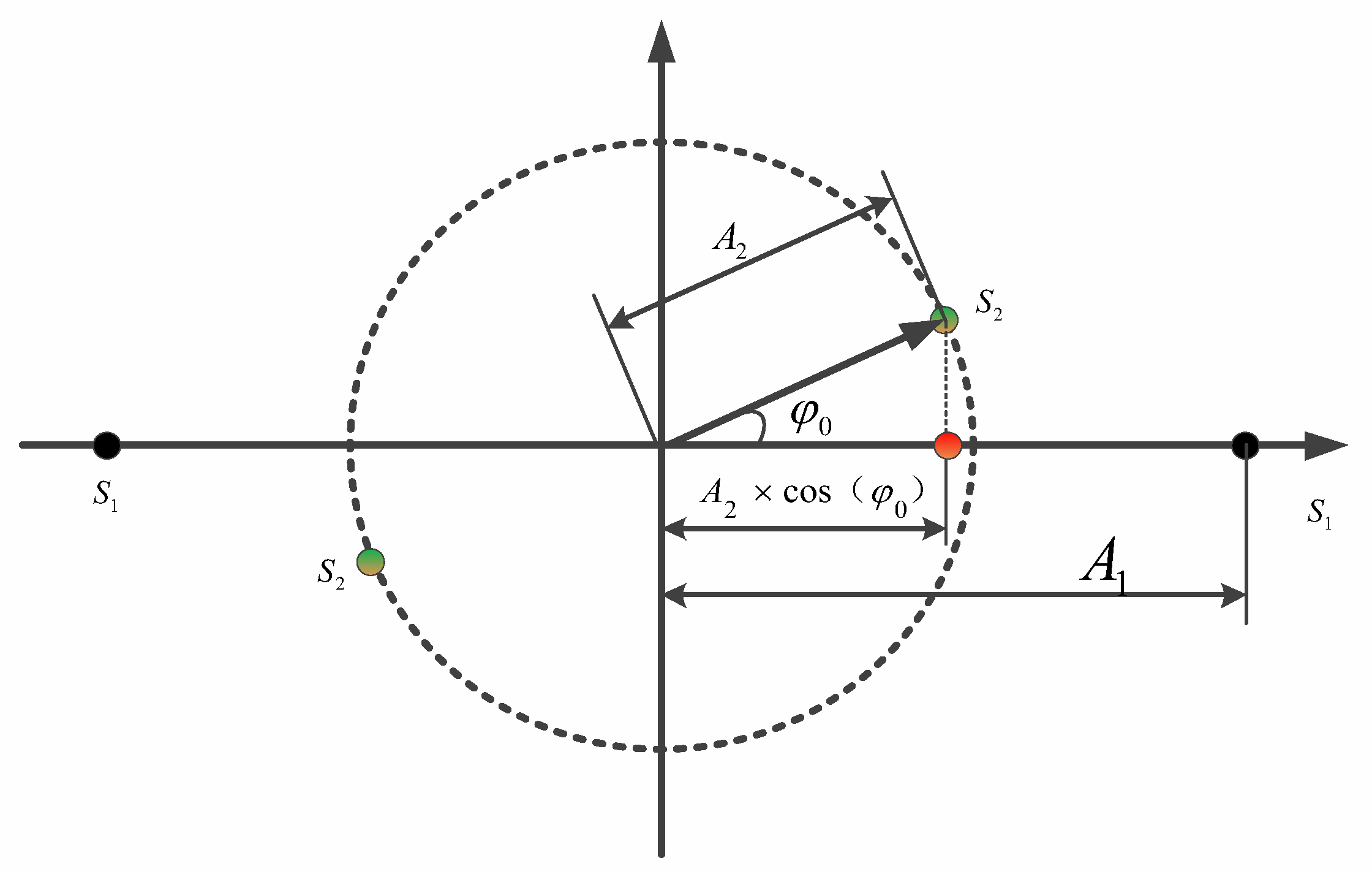
For the second signal S 2 , consider practical impairments such as frequency offset and phase offset. Ignoring frequency deviation for now and modeling the phase offset as ϕ 1 , the effective amplitude becomes A 2 × cos ( ϕ 1 ) , as shown in Figure 5.
Assumed noise variance is σ, the BER then becomes
P ( 1 , 1 ) S 1 S 2 1 ( 1 , 1 ) = A 1 + A 2 × cos   ϕ 1 + 1 2 π σ e - t 2 2 σ 2 d t .
P ( 1 , - 1 ) S 1 S 2 1 ( 1 , - 1 ) = A 1 A 2 × cos   ϕ 1 + 1 2 π σ e - t 2 2 σ 2 d t .
P ( 1 , 1 ) S 1 S 2 1 ( 1 , 1 ) = A 1 A 2 × cos   ϕ 1 + 1 2 π σ e t 2 2 σ 2 d t .
P ( 1 , 1 ) S 1 S 2 1 ( 1 , 1 ) = A 1 + A 2 × cos   ϕ 1 + 1 2 π σ e t 2 2 σ 2 d t .
Substituting Equations (8)–(11) into Equation (7) yields
B E R B P S K = 1 2 × A 1 + A 2 × cos   ϕ 1 + 1 2 π σ e t 2 2 σ 2 d t + 1 2 × A 1 A 2 × cos   ϕ 1 + 1 2 π σ e t 2 2 σ 2 d t .
If μ = 0 , σ = 1 , then for the signal S 1 : E b = 2 S N R  and A 1 = 2 S N R , the BER expression simplifies to
B E R B P S K = 1 2 × 2 S N R   1 + 1 W × cos   ϕ 1 + 1 2 π e t 2 2 d t + 1 2 × 2 S N R   1 1 W × cos   ϕ 1 + 1 2 π e t 2 2 d t   = 1 2 × Q [ 2 S N R   1 + 1 W 1 × cos   ϕ 1 ] + 1 2 × Q [ 2 S N R   1 1 W 1 × cos   ϕ 1 ] .
According (13), three major factors influence the BER of the first signal:
  • SNR of the primary signal ( A 1 S 1 n );
  • Amplitude ratio W 1 = A 1 A 2 ;
  • Real-time phase offset of the secondary signal φ1.
Considering that the phase offset ϕ 0  of the second signal is uniformly distributed (as it is independent from the first signal over time), the average BER can be expressed as
B E R B P S K = 1 M i = 0 M 1 1 2 × Q [ 2 S N R   1 + 1 W × cos   ( 2 × π × i - M 2 M ) ] + 1 2 × Q [ 2 S N R   1 1 W × cos   ( 2 × π × i - M 2 M ) ] M + .

2.3. Theoretical Performance Analysis for Three Overlapping Signals

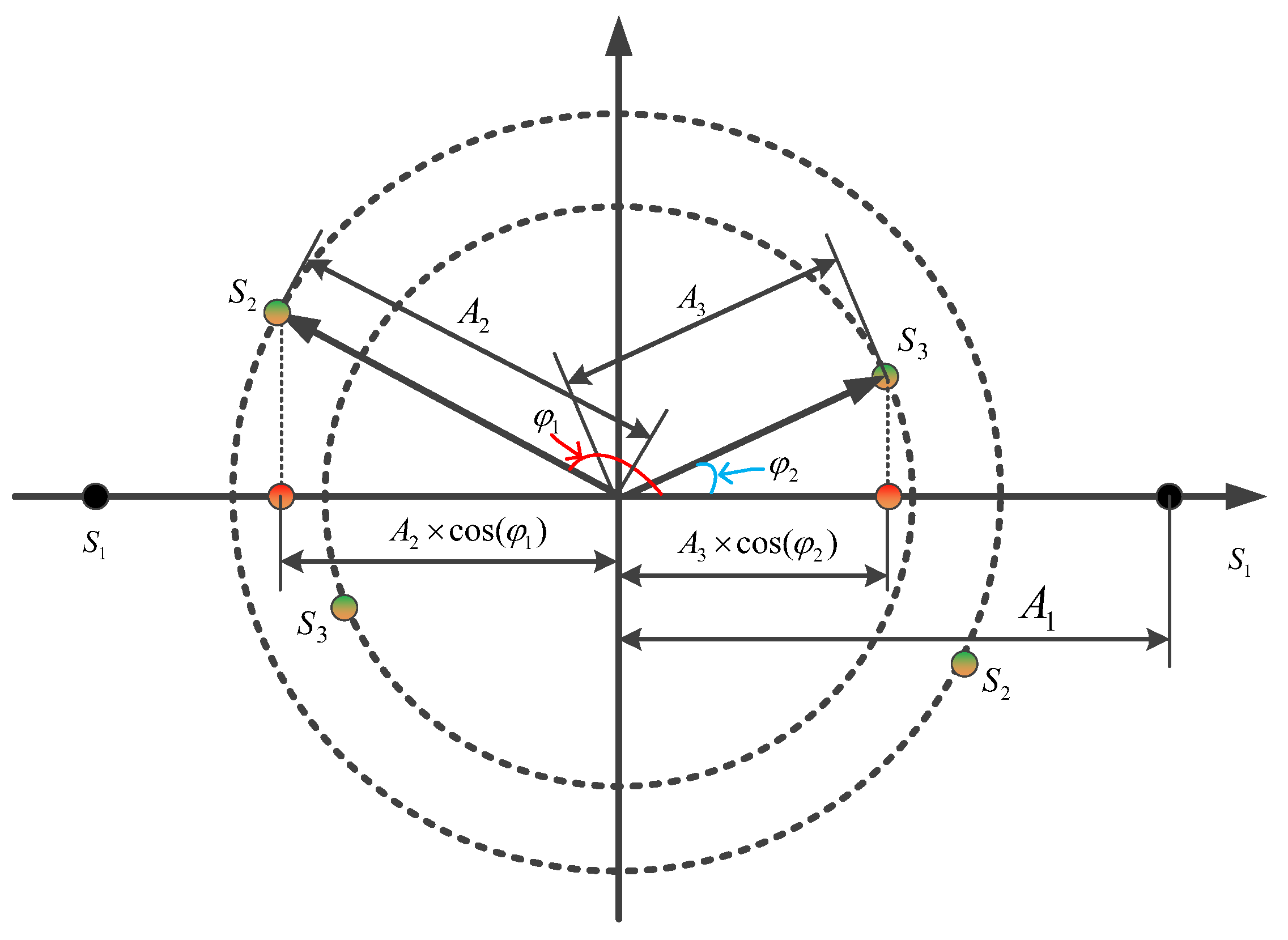
As shown in Figure 6, building upon the theoretical derivation from the two-signal case, the BER expression for the first signal in a three-user superimposed SIC system can be extended as follows:
B E R B P S K = 1 4 × Q [ 2 S N R   1 + 1 W 1 × cos   ϕ 1 + 1 W 2 × cos   ϕ 2 ] + 1 4 × Q [ 2 S N R   1 + 1 W 1 × cos   ϕ 1 1 W 2 × cos   ϕ 2 ] + 1 4 × Q [ 2 S N R   1 1 W 1 × cos   ϕ 1 + 1 W 2 × cos   ϕ 2 ] + 1 4 × Q [ 2 S N R   1 1 W 1 × cos   ϕ 1 1 W 2 × cos   ϕ 2 ] .
The BER performance of the primary signal in a three-layer SIC system is influenced by the following five key factors:
  • SNR of the first signal;
  • Amplitude ratio between the first and second signals W 1
  • Amplitude ratio between the first and third signals W 2 ;
  • Instantaneous phase offset of the second signal φ1;
  • Instantaneous phase offset of the third signal φ2.
Based on the above principles, the analysis of M-heavy signals is as follows:
K i = 10 1 g   ( A 1 2 A i + 1 2 ) , i 1 , M 1 .
At the same time, the amplitude ratio of the signal and the signal A 1   A i + 1 is defined as
W i = A 1 A i + 1 , A i + 1 = A 1 W i , W i = 10 K i 20 .
Based on this, the theoretical bit error performance of the first heavy signal of the NMA-BPSK signal of the M heavy signal is as follows:
B E R B P S K = μ = 1 2 M 1 1 2 M 1 × Q 2 S N R ×   1 + γ = 1 M 1   1 μ × γ 1 γ × 2 M γ 1 × 1 W γ × cos   ϕ γ .

3. Proposed Modeling

3.1. Carrier Synchronization Algorithmsfor Burst Signals

3.1.1. Common Carrier Synchronization Algorithms

Carrier synchronization is a critical component in burst-mode communication systems. According to relevant research, carrier synchronization can be broadly divided into closed-loop and open-loop approaches.
Closed-loop synchronization algorithms are widely used. Reference [11] describes a high-performance fine phase recovery method that has been widely adopted in DVB-S2 receivers. The process includes:
  • Multiplying the input sampled signal with two locally generated orthogonal carriers;
  • Filtering and demodulating the resulting phase detection signal;
  • Feeding the output to a phase detector to generate an error signal;
  • Filtering this error through a loop filter to control a numerically controlled oscillator (NCO), which regenerates the local carrier;
  • Forming a feedback loop by mixing the local carrier with the input signal again.
Loop filters are typically implemented as second- or third-order filters to ensure accurate tracking of phase, frequency, and their variations. The loop bandwidth is a key parameter that directly impacts acquisition speed and synchronization accuracy—therefore, it must be carefully optimized. As shown in Figure 7, the closed-loop carrier synchronization architecture illustrates the detailed process involved in this method, providing a clear view of the feedback loop and phase recovery mechanism.
Open-loop carrier frequency estimation algorithms are mainly categorized into:
  • Frequency-domain estimation, such as the method in [12], which detects coarse frequency by searching for spectral peaks and then refines using spectral features;
  • Time-domain estimation, which extracts frequency offset from signal autocorrelation.
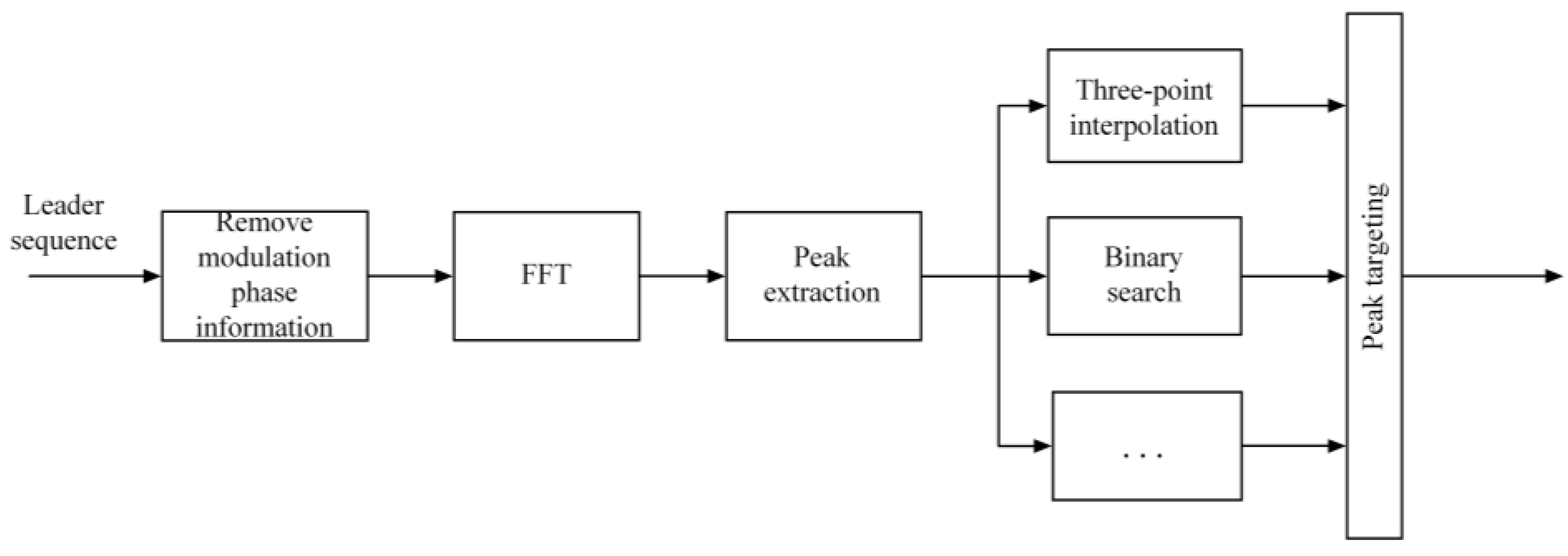
In the time domain, the Kay estimator and its variants can achieve high precision under strong SNR conditions [13,14,15]. In the frequency domain, the Rife algorithm and its improvements rely on cyclic spectral analysis [16,17,18,19,20,21]. Figure 8 depicts the architecture for open-loop frequency estimation, highlighting the techniques used for coarse frequency detection and fine refinement.
Recent literature also proposes hybrid synchronization techniques that combine open-loop and closed-loop mechanisms. These methods use the signal preamble for initial frequency and phase offset estimation, and then switch to closed-loop tracking for robust carrier synchronization [7]. The structure of this hybrid approach is illustrated in Figure 9, showcasing the transition from open-loop estimation to closed-loop tracking for improved synchronization accuracy and reliability.

3.1.2. Carrier Synchronization for Dual-Signal SIC Reception

From the simulation results, we observe that at high SNR, conventional closed-loop carrier tracking algorithms can quickly acquire lock. However, in low SNR environments, the locking process slows down significantly. This represents a fundamental trade-off in closed-loop methods: maintaining high tracking accuracy at low SNR necessitates a narrow loop bandwidth, which inherently prolongs the acquisition time. This challenge is particularly significant in burst-mode communications, where the signal duration is short and fast carrier acquisition is essential.
In contrast, open-loop methods offer faster acquisition times but typically require higher SNR to achieve reliable estimates. At low SNR, their estimation precision drops, making it harder for closed-loop tracking to complete the lock within the limited burst duration.
As such, current synchronization algorithms struggle to satisfy the demands of low-SNR, high-efficiency burst communications, highlighting the need for more advanced hybrid or adaptive methods.

3.2. Capacity Enhancement via Pre-Frequency Offset and Dual-Parameter Iterative Carrier Synchronization

Based on the preceding analysis of SIC in beam-hopping systems, it can be concluded that uplink capacity enhancement depends on the following key factors:
  • Optimizing the SNR of the primary signal;
  • Maintaining an appropriate power ratio between the primary and secondary signals;
  • Ensuring uniform phase distribution at each sampling point for the secondary signal;
  • Improving the efficiency of burst frame structure.
To address these challenges, we propose a method for enhancing capacity by combining pre-configured frequency offsets with bi-directional adaptive iterative carrier synchronization.
The core idea involves pre-introducing a small, fixed frequency offset—typically within 1% of the symbol rate—to the secondary and tertiary signals at the transmitter. This intentional offset reduces interference with the primary signal. As illustrated in Figure 10, which shows a three-signal system with pre-configured offsets, the technique minimizes interference by applying frequency shifts to the non-primary signals.
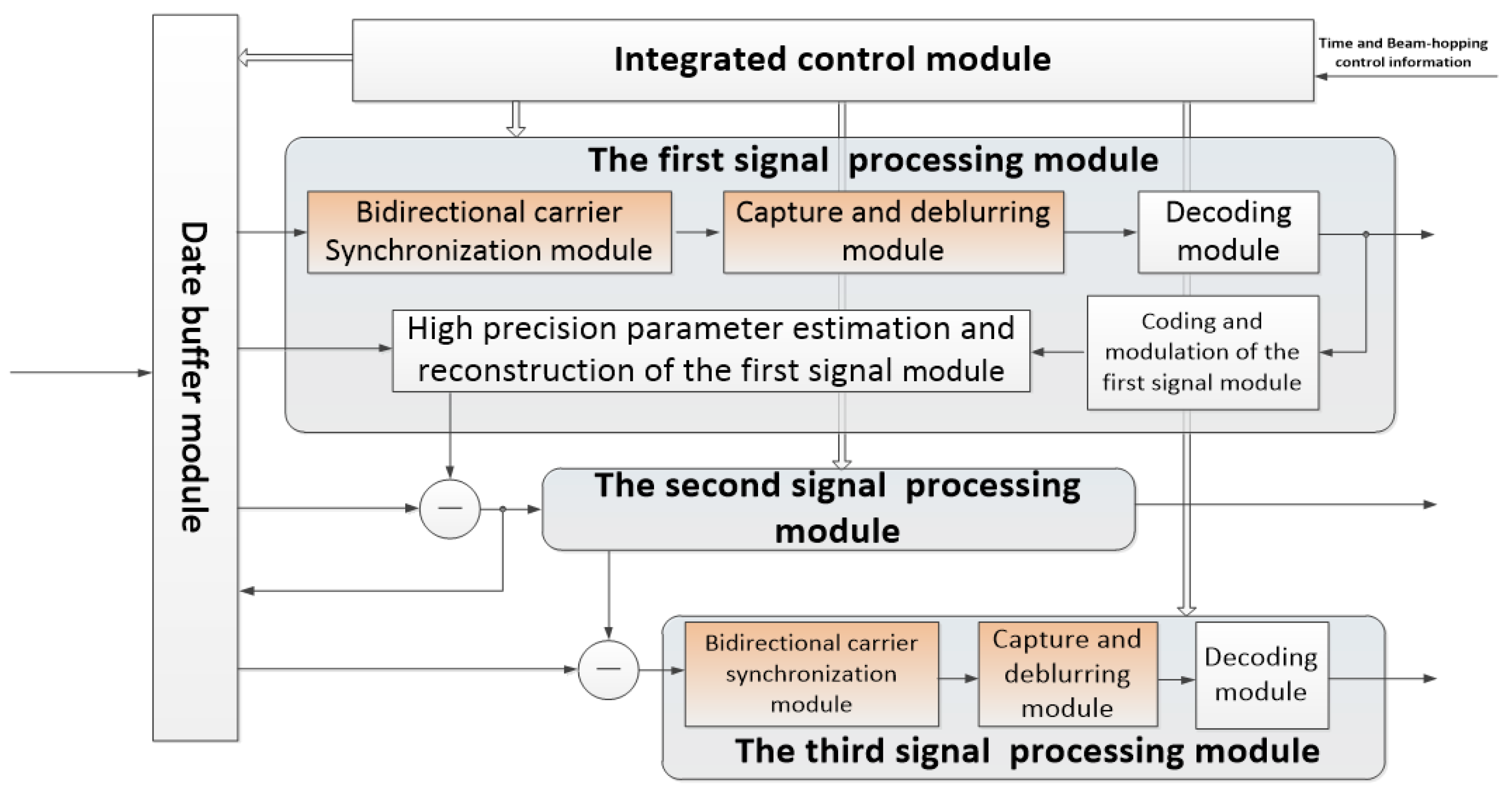
In addition, we designed an efficient burst frame structure tailored to the receiver’s processing method. This is complemented by bi-directional adaptive phase-locked loop (PLL) synchronization, which improves lock acquisition probability. The multi-signal reception and processing flow, detailed in Figure 11, demonstrates how the receiver handles different signals and applies the proposed synchronization technique to ensure optimal performance.

3.2.1. Dual-Parameter Iterative Carrier Synchronization

In coherent communication systems, the PLL and its variants play a critical role in system performance. A typical second-order digital PLL phase model is shown in Figure 12, which illustrates the phase model of a second-order digital PLL, providing a foundational view of the PLL’s operation in the context of phase synchronization.
In this model, K = K d K o  represents the loop gain, and c 1  and c 2  are the digital loop parameters. The equivalent phase noise, caused by input white noise and filtered through the loop, can be expressed as:
σ θ n o 2 = S N i 1 B L B i
where B i  is the bandwidth of the loop’s frontend filter, S / N i  is radio between the input signal power, and the noise power passing through the frontend filter. The loop noise bandwidth is represented as B L .
The loop’s ability to suppress noise can be quantified by the loop’s SNR, defined as:
S N L = 1 σ θ n o 2 = S N i B i B L
Phase noise directly affects the BER. For a given target BER, the corresponding loop SNR can be calculated. In practical communication systems, the input SNR ( S / N i ) and the frontend filter bandwidth B L  are predefined. To ensure that the system maintains an acceptable BER under low SNR conditions and to control the loop’s frequency locking probability, it is necessary to narrow the loop bandwidth B i . However, narrowing the loop bandwidth increases the capture and lock-in time of the PLL, leading to a trade-off between fast synchronization and low SNR operation.
This trade-off is particularly problematic for burst signal demodulation, where a longer lock-in time caused by the narrowed PLL bandwidth makes it difficult to meet burst signal synchronization requirements, especially in high-efficiency burst systems that require signal capture with very short preambles.
To address this issue, we propose drawing inspiration from iterative decoding techniques. By storing the input signal and using the frequency and phase estimates from the previous loop stage as starting points, burst signals can be processed using bi-directional adaptive iteration, which significantly accelerates the PLL’s lock-in time.
The need for bi-directional iteration arises because frequency estimates in the loop are direction-dependent. Specifically, the frequency estimate for forward and reverse processing has opposite signs. To maintain phase continuity during the iteration process, the sign of the frequency estimate must be inverted when reversing the direction. This bi-directional iterative carrier synchronization approach allows for continuous adjustment of loop parameters, optimizing the loop’s SNR and behavior at different stages, and ultimately achieving superior synchronization performance.
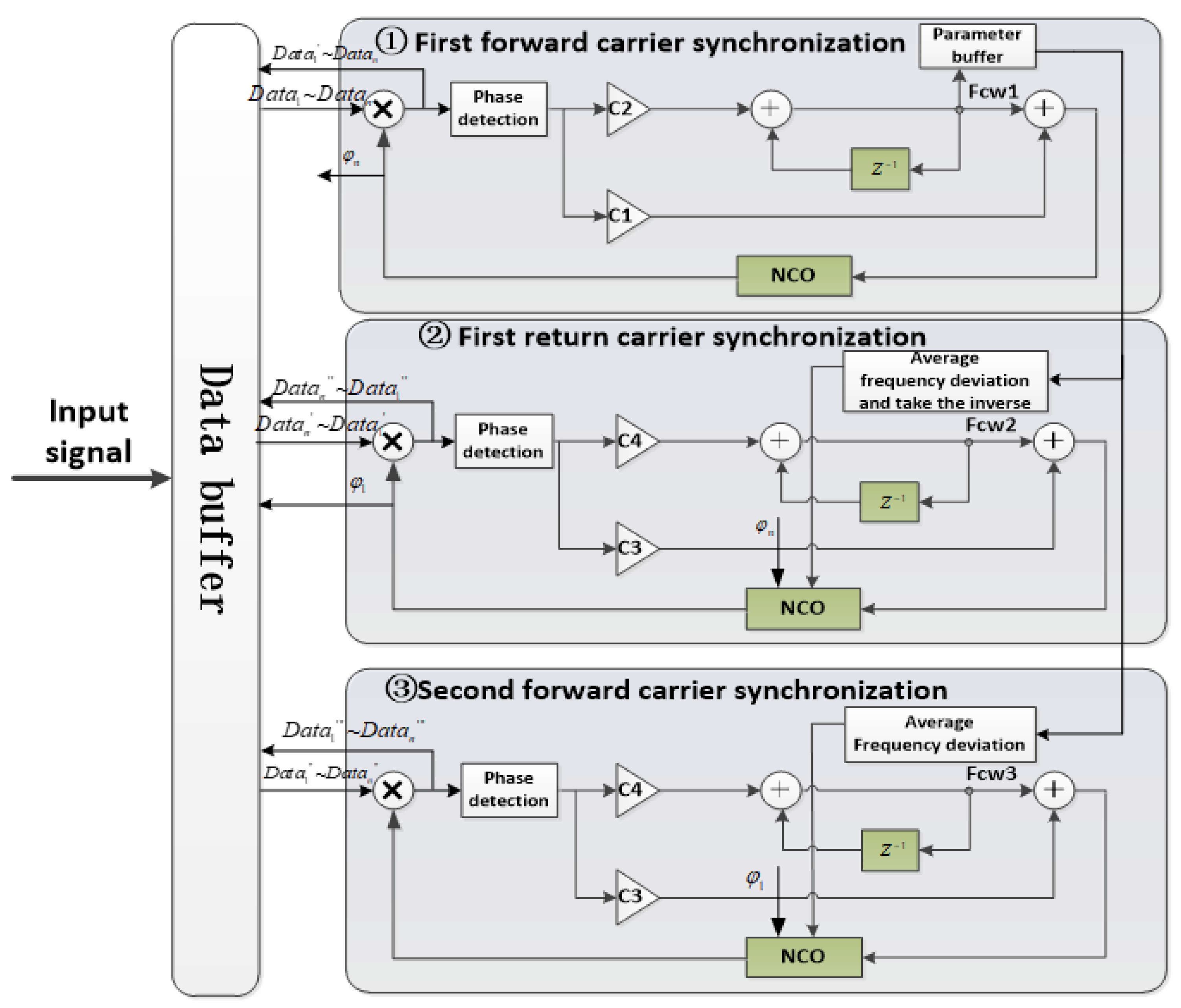
The processing flow for each burst data block when using the bi-directional adaptive iterative carrier synchronization algorithm in a second-order PLL is illustrated in Figure 13. This structure highlights the iterative process, where the loop parameters are adapted in each pass to optimize synchronization performance. During iteration, loop parameters can be adapted to optimize synchronization behavior in each pass.
Algorithm Steps:
  • Signal Buffering: The input signal is buffered using the time-slot synchronization signal in the beam-hopping communication system. A complete burst time-slot signal is stored.
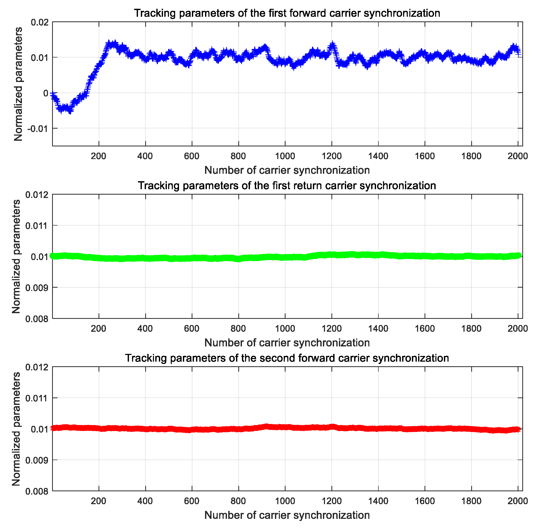
  • First Forward Carrier Synchronization: The process begins with the first forward synchronization using relatively wide loop parameters. Specifically, the PLL parameters C1 and C2 are calculated. The data is sequentially read from the buffer, and the PLL is used for forward carrier synchronization until the entire burst frame is processed. During this process, the frequency estimate F c w 1  is stored, along with the final phase value ϕ n  of the PLL’s Numerically Controlled Oscillator (NCO). The carrier-synchronized data is D a t a 1 ~ D a t a n  then cached.
  • First Reverse Carrier Synchronization: Next, the first reverse carrier synchronization is performed with narrower loop parameters, calculated as C3 and C4. The frequency estimate F c w 1  from the first forward synchronization is averaged, with the latter half of the data selected for averaging (typically more than 100 symbols, depending on burst time). The loop frequency control word is inverted F c w 1  and the NCO phase ϕ n  is initialized to the last tracked phase value from the first forward synchronization. The data D a t a 1 ~ D a t a n  is then read in reverse from the buffer and the PLL is applied for reverse carrier synchronization. The NCO’s final output phase ϕ 1  is stored, and the reverse-synchronized data D a t a n ~ D a t a 1  is cached.
  • Second Forward Carrier Synchronization: The second forward carrier synchronization is performed using a narrower loop bandwidth, with PLL parameters C3 and C4 derived from the reverse synchronization step. The frequency estimate F c w 1  from the first forward synchronization is averaged using the frequency value from the reverse pass F c w 1 . The NCO phase is initialized with the last tracked phase ϕ 1  from the reverse synchronization. Data D a t a n   D a t a 1  is then read in sequence from the buffer, and forward carrier synchronization is carried out. The synchronized data D a t a 1 ~ D a t a n  is stored.
The pseudocode described above is shown as Algorithm 1.
Algorithm 1: Bi-Directional Adaptive Synchronization
  INPUT: raw_signal, beam_hopping_sync_signal
  OUTPUT: synced_signal
  //Step 1: Signal Buffering
  BEGIN
  burst_signal = BUFFER_SIGNAL(raw_signal, beam_hopping_sync_signal)
  INITIALIZE buffer WITH burst_signal
  L = LENGTH(burst_signal)
  //Step 2: First Forward Synchronization (Wide Bandwidth)
  SET PLL_PARAMS = {C1, C2}//Wide loop parameters
  INITIALIZE forward_pll WITH PLL_PARAMS
  INITIALIZE forward_phase_estimate [1..L]
  INITIALIZE forward_freq_estimate [1..L]
  INITIALIZE data_forward1[1..L]
  FOR i = 1 TO L DO
  symbol = READ_BUFFER(buffer, i)
  (synced_symbol, phase, freq) = forward_pll.PROCESS(symbol)
  data_forward1[i] = synced_symbol
  forward_phase_estimate[i] = phase
  forward_freq_estimate[i] = freq
  END FOR
  stored_freq_est1 = forward_freq_estimate[L]
  stored_phase_est1 = forward_phase_estimate[L]
  //Step 3: First Reverse Synchronization (Narrow Bandwidth)
  SET PLL_PARAMS = {C3, C4}//Narrow loop parameters
  INITIALIZE reverse_pll WITH PLL_PARAMS
  INITIALIZE reverse_phase_estimate [1..L]
  INITIALIZE data_reverse [1..L]
  //Average frequency estimate (last N symbols, N ≥ 100)
  avg_freq = MEAN(forward_freq_estimate[L-99:L])
  reverse_pll.SET_FREQUENCY(-avg_freq)//Invert frequency control
  reverse_pll.SET_INITIAL_PHASE(stored_phase_est1)
  FOR i = L DOWNTO 1 DO
  symbol = READ_BUFFER(buffer, i)
  (synced_symbol, phase, freq) = reverse_pll.PROCESS(symbol)
  data_reverse[i] = synced_symbol
  reverse_phase_estimate[i] = phase
  END FOR
  stored_phase_est2 = reverse_phase_estimate [1]
  //Step 4: Second Forward Synchronization (Narrow Bandwidth)
  SET PLL_PARAMS = {C3, C4}//Narrow loop parameters
  INITIALIZE final_pll WITH PLL_PARAMS
  INITIALIZE synced_signal [1..L]
  final_pll.SET_INITIAL_PHASE(stored_phase_est2)
  final_freq = (avg_freq + reverse_pll.GET_FREQ_ESTIMATE())/2
  final_pll.SET_FREQUENCY(final_freq)
  FOR i = 1 TO L DO
  symbol = READ_BUFFER(buffer, i)
  (synced_symbol, phase, freq) = final_pll.PROCESS(symbol)
  synced_signal[i] = synced_symbol
  END FOR
  RETURN synced_signal
END ALGORITHM
The bi-directional adaptive iterative carrier synchronization algorithm is set to a maximum number of iterations (usually 3), and the process terminates when the maximum number of iterations is reached.

3.2.2. Optimized High-Efficiency Burst Frame and Capture Method

The traditional burst signal transmission frame structure is shown below and primarily consists of a synchronization preamble, UW, service data, and guard intervals before and after the burst signal. The synchronization preamble is used for carrier synchronization, bit synchronization, and signal capture, while the UW is employed for phase deambiguation and frame synchronization. The service data represents the actual transmitted information, typically spanning more than one coding block.
Due to the long training sequences required for carrier and bit synchronization, the length of the synchronization preamble is generally greater than 100 symbols, and the length of the unique word is typically over 32 symbols. Depending on factors such as transmission burst rate and service data length, the transmission efficiency of traditional burst signals generally ranges between 75% and 85%. Figure 14 illustrates the structure of a traditional burst frame, showing the typical arrangement of the sync preamble, UW, payload data, and guard intervals.
To address this, we propose a high-efficiency frame structure based on the synchronization algorithm above. It uses dual unique words and guard intervals, significantly reducing overhead. Efficiency can reach 92–97%. Figure 15 presents the optimized burst frame structure, highlighting the use of dual unique words and guard intervals for enhanced efficiency.
The proposed method for burst signal capture, in conjunction with the optimized transmission frame structure, is outlined as follows:
  • Signal Buffering: Utilize the time-slot synchronization signal in the beam-hopping communication system to buffer the incoming signal, capturing a complete burst time-slot signal.
  • Carrier Synchronization: Perform three iterations of carrier synchronization using the bi-directional adaptive iterative carrier synchronization algorithm outlined in Section 4.1.
  • First Half of Reverse Synchronization: After the first reverse synchronization, extract the first half of the synchronized data sequence and generate the inverted version of the sequence.
  • Second Half of Forward Synchronization: After the second forward synchronization, extract the second half of the synchronized data sequence and generate the inverted version of the sequence.
  • Data Combination: Combine the four sequences from steps 3 and 4 to form a new set of four data sequences, as shown in (16).
    S 1 D a t a 1 ~ D a t a n 2 , D a t a ( n 2 + 1 ) ~ D a t a n S 2 D a t a 1 ¯ ~ D a t a n 2 ¯ , D a t a ( n 2 + 1 ) ~ D a t a n S 3 D a t a 1 ~ D a t a n 2 , D a t a ( n 2 + 1 ) ¯ ~ D a t a n ¯ S 4 D a t a 1 ¯ ~ D a t a n 2 ¯ , D a t a ( n 2 + 1 ) ¯ ~ D a t a n ¯
  • Correlation and Capture: For the four sequences obtained in Step 5, identify the positions of the local UW and correlate each sequence with the local UW. The sequence with the highest correlation value is selected as the correctly captured sequence.

4. Numerical Results

4.1. Performance for Two or Three Overlapping Signals

To validate the closed-form BER expressions derived in Section 2.2 (Equation (7) for two-signal) and Section 2.3 (Equation (15) for three-signal), we conduct Monte Carlo simulations under worst-case phase alignment conditions where θ2 = 0° (two-signal) and θ2 = θ3 = 0° (three-signal). The simulation parameters strictly follow the theoretical assumptions in Section 2.1:
-
AWGN channel with perfect time synchronization;
-
BPSK modulation with independent symbol streams;
-
Fixed amplitude ratio α = A2/A1 for two-signal case;
-
Dual amplitude ratios β = A2/A1, γ = A3/A1 for three-signal case.
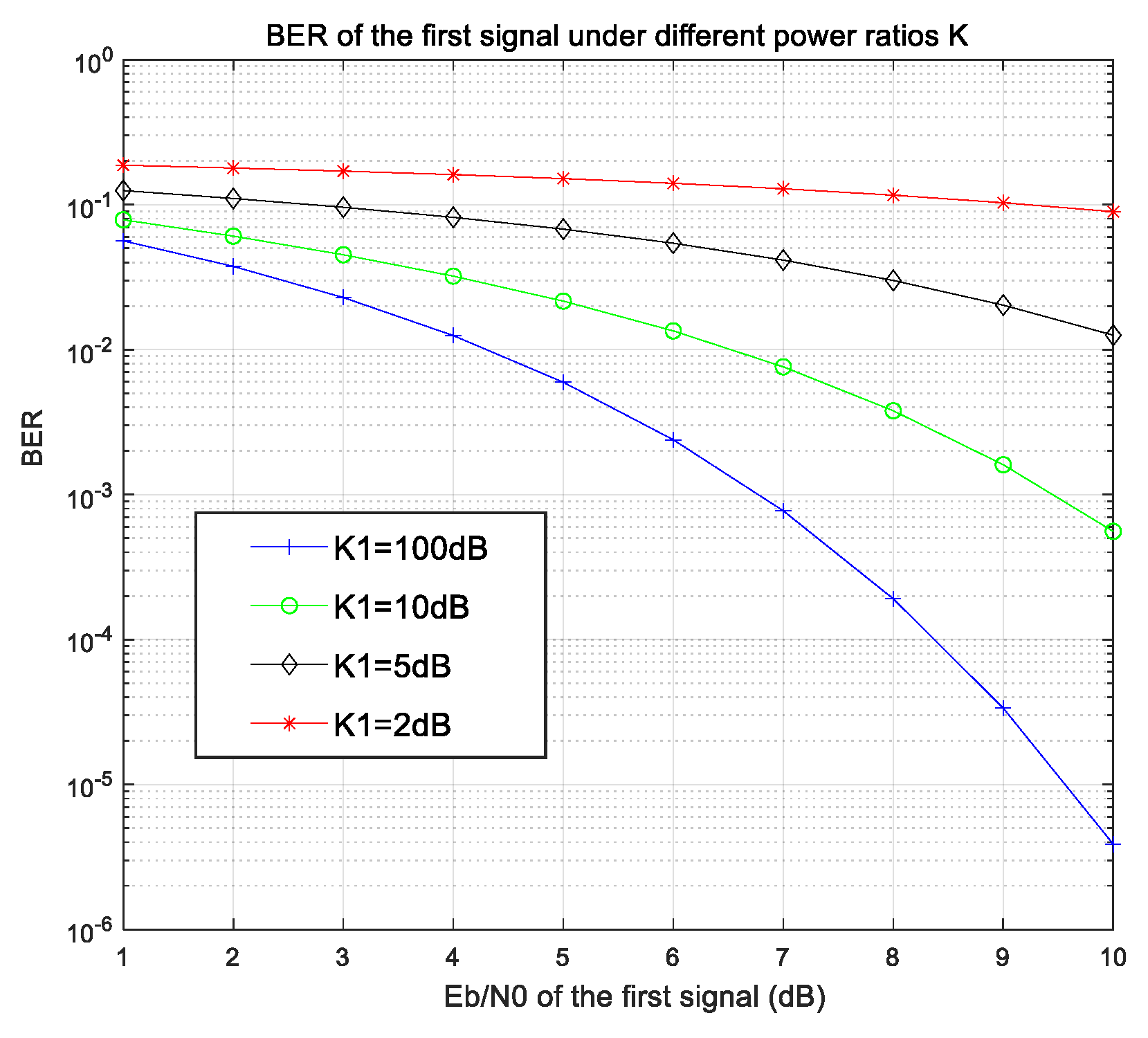
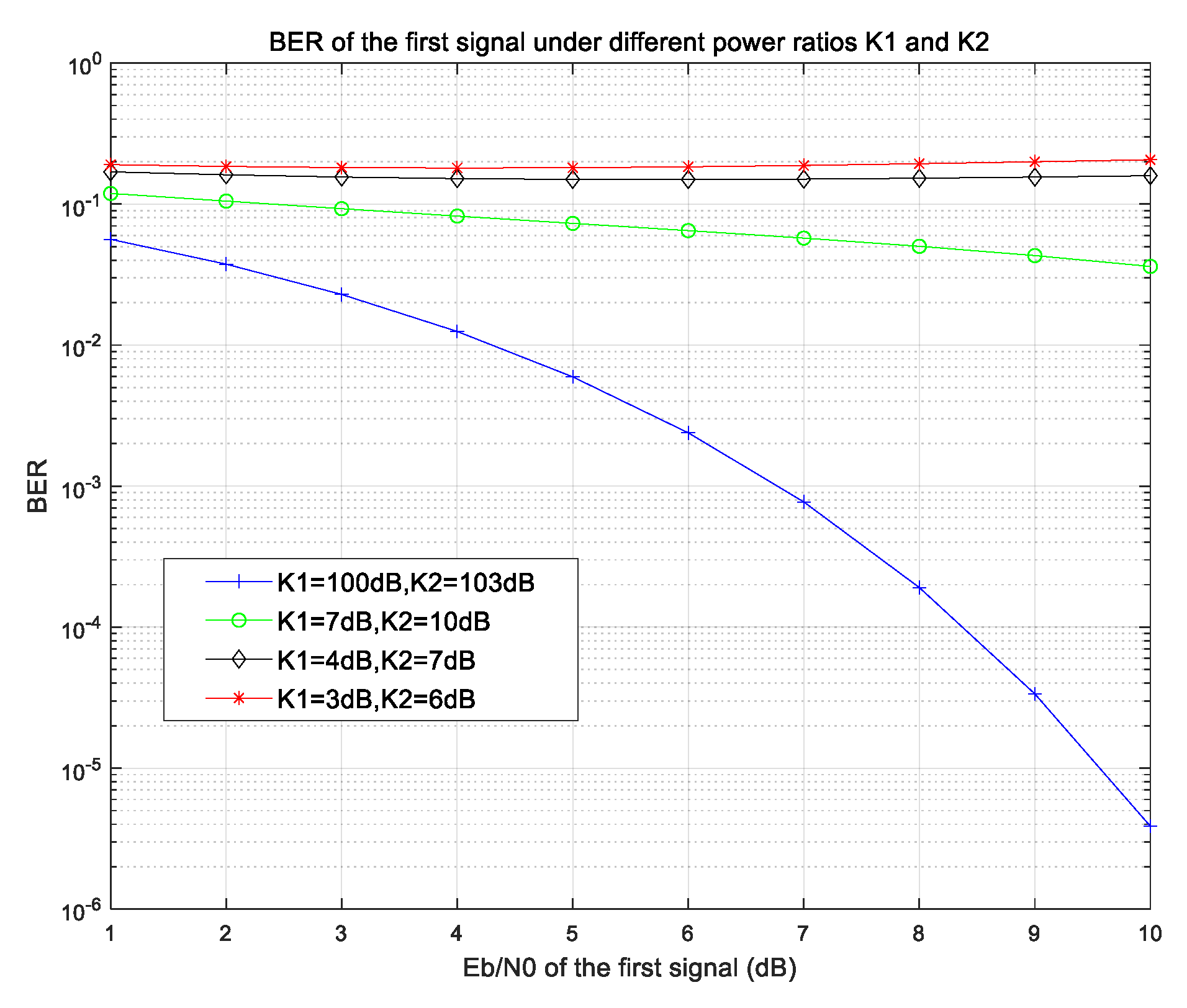
Figure 16 demonstrates how the BER of the primary signal degrades with increasing interference power (decreasing α). At α = 0.3 (strong interference), achieving 10−5 BER requires 3 dB higher SNR compared to α = 0.8. This experimentally confirms the interference sensitivity predicted by Equation (12).
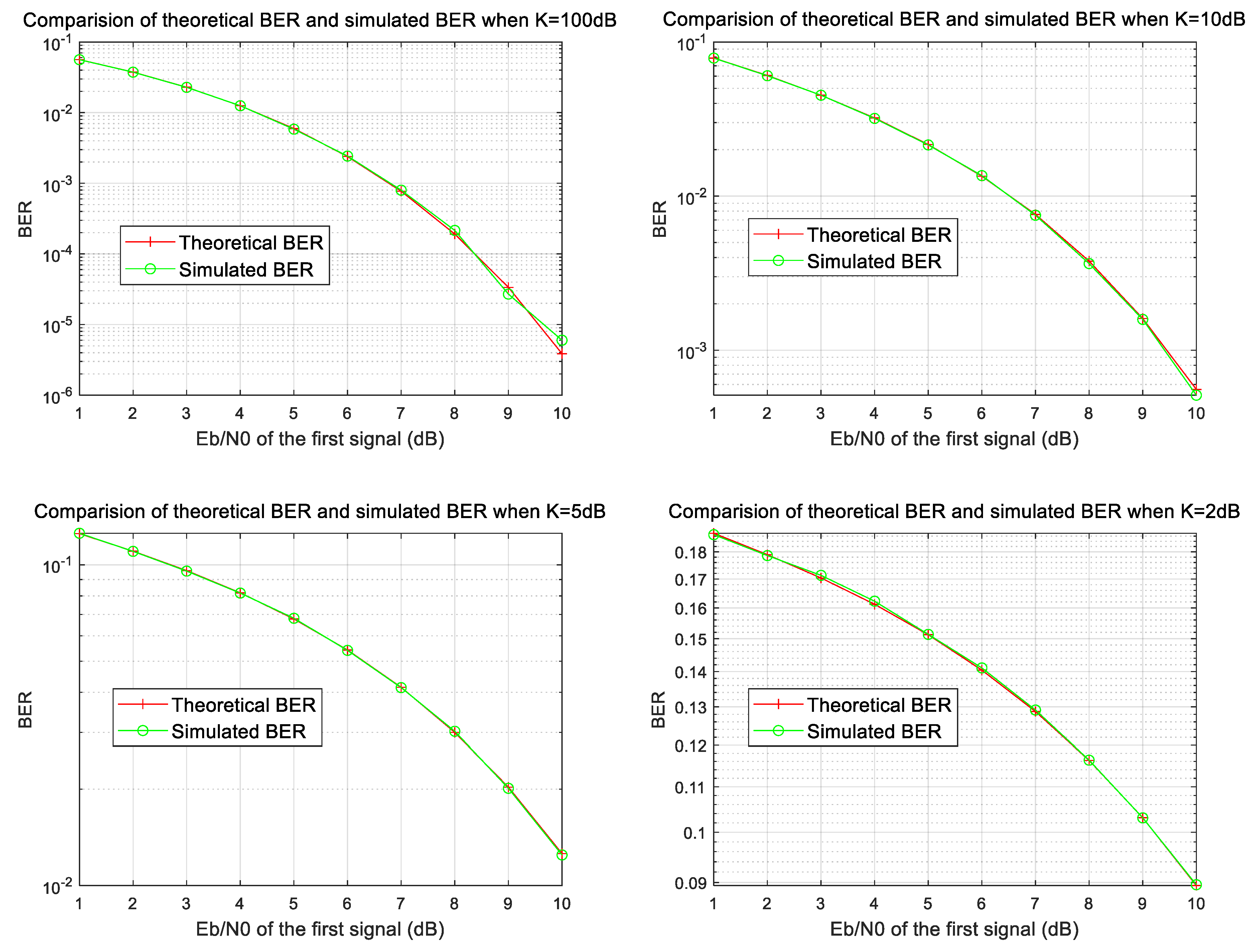
More significantly, Figure 17 provides direct validation of our theoretical model. The maximum deviation between simulation (200,000 samples per point) and theory remains below 0.15 dB across the operational SNR range (0–8 dB), with particularly close alignment at the 4–6 dB range typical for satellite links. This accuracy enables reliable system design without exhaustive simulations.
For the three-signal scenario (Figure 18), we observe similar high-fidelity matching. The ‘stair-step’ characteristic at β = 0.4, γ = 0.6 originates from the composite interference mechanism described in Equation (15)—a phenomenon not captured in prior simplified models [9]. In the simulation, we incorporated Monte Carlo parameters and evaluated the BER performance of NOMA-BPSK under different codeword lengths, specifically N = 1024, 128, and 32. The random phase parameters were generated using a fixed seed (rng(123)) to ensure reproducibility. Additionally, a new table, as shown in Table 2, has been added to summarize the variance and standard deviation of the simulation results at Eb/N0 = 6 dB for different Monte Carlo settings. This provides a quantitative measure of the impact of the Monte Carlo parameters on the simulation accuracy.
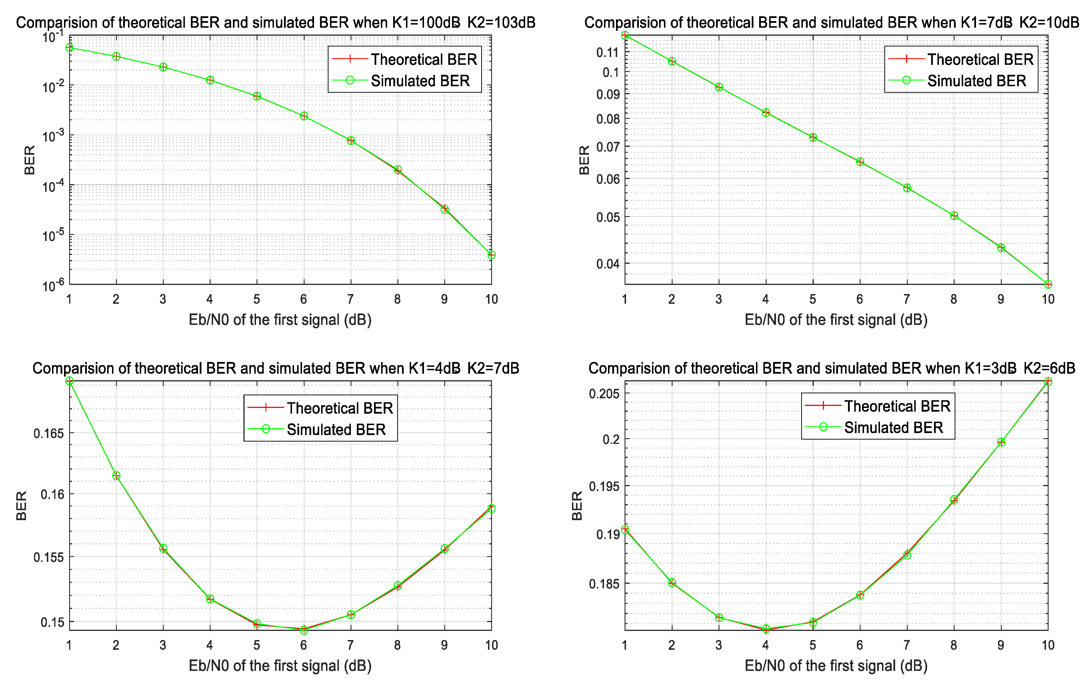
To validate the accuracy of the theoretical expression, simulations are conducted to observe the BER performance of the first signal under different power and phase offset conditions. The results are shown in Figure 19 and Figure 20. The simulations consider the worst-case condition where both phase offsets are zero. The comparison between theoretical predictions and simulation results shows excellent agreement, thereby confirming the accuracy and robustness of the derived analytical expression for the three-signal SIC scenario.

4.2. Carrier Synchronization Performance for Burst Signals

The synchronization challenges identified in Section 3.1.2 manifest clearly in our simulations. To evaluate the synchronization performance under SIC (Serial Interference Cancelation) with two superimposed signals, simulations were conducted using the following parameters as Table 3.
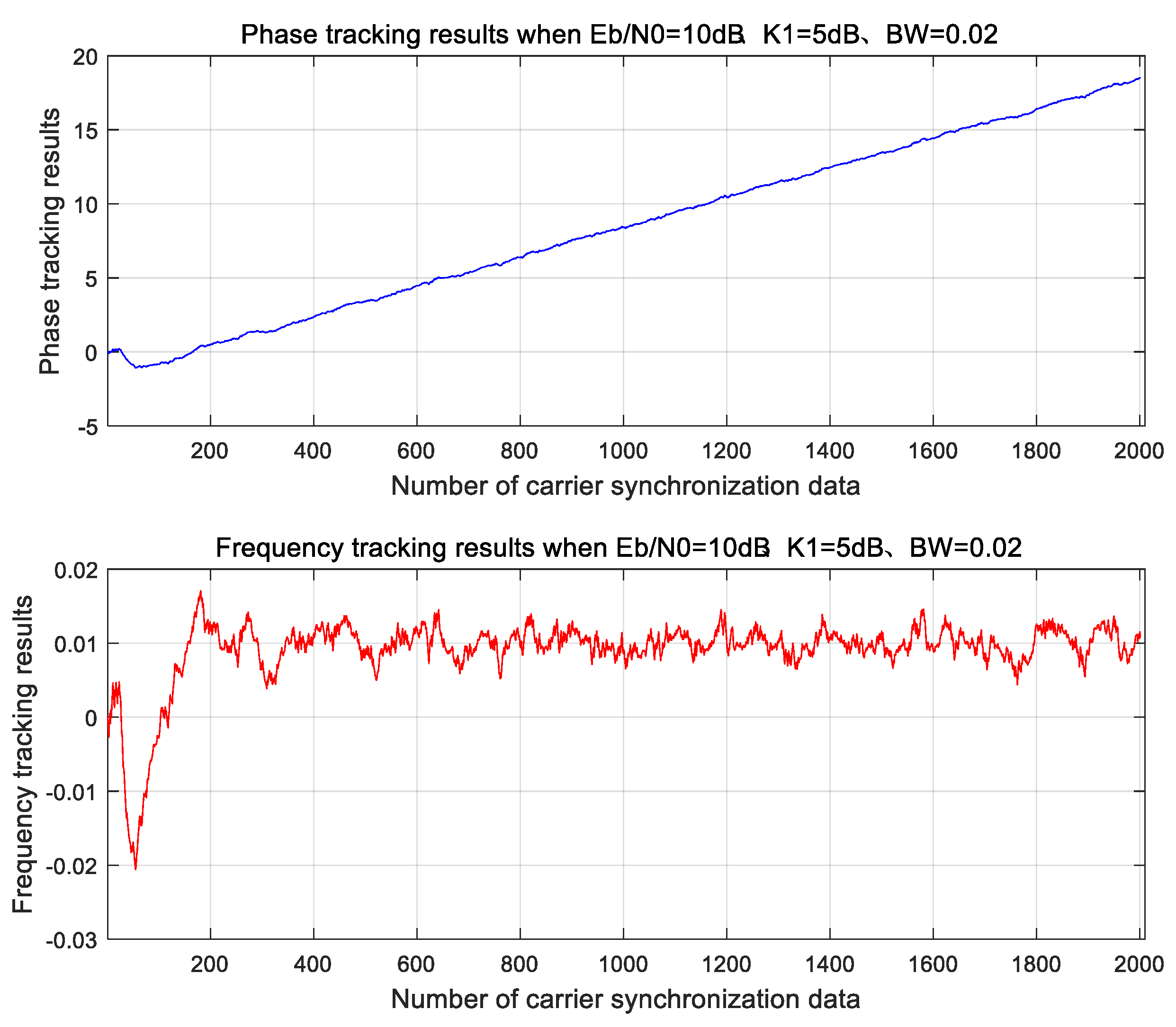
Figure 21 confirms that conventional closed-loop PLL (architecture shown in Figure 12) achieves rapid lock (<50 symbols) at high SNR (Eb/N0 = 10 dB) with wide bandwidth (0.02 × Rs). However, under the more realistic low-SNR condition (Eb/N0 = 4 dB) required for capacity enhancement:
  • Narrow-band PLL (BW = 0.005 × Rs) fails to lock within 2000-symbol burst (Figure 16).
  • Required acquisition time exceeds 400 symbols—consuming >20% of typical beam dwell time.
  • Residual phase error exceeds 15° RMS, violating the θ2 < 5° requirement derived in Section 2.2.
This performance gap directly motivates our hybrid synchronization scheme in Section 4.3. Specifically, the slow convergence stems from two fundamental limitations analyzed in Section 3.1.1:
(a)
The noise-bandwidth tradeoff in second-order PLLs Equation (19).
(b)
The preamble length constraint (≤100 symbols) in efficient burst systems.
In contrast, Figure 22 illustrates carrier tracking in a low SNR scenario with a narrower loop bandwidth of 0.005. In this case, the locking process significantly slows down, highlighting the challenges of closed-loop methods in low-SNR environments. To maintain high tracking accuracy in such conditions, a narrow loop bandwidth must be employed, which results in a slower acquisition time.
From the simulation results, we observe that at high SNR, conventional closed-loop carrier tracking algorithms can quickly acquire lock. However, in low SNR environments, the locking process slows down significantly. This is a common limitation of closed-loop methods: to maintain high tracking accuracy at low SNR, a narrow loop bandwidth must be used, which inherently increases the acquisition time. This challenge is particularly significant in burst-mode communications, where the signal duration is short and fast carrier acquisition is essential.
In contrast, open-loop methods offer faster acquisition times but typically require higher SNR to achieve reliable estimates. At low SNR, their estimation precision drops, making it harder for closed-loop tracking to complete the lock within the limited burst duration.
As such, current synchronization algorithms struggle to satisfy the demands of low-SNR, high-efficiency burst communications, highlighting the need for more advanced hybrid or adaptive methods.

4.3. Pre-Frequency Offset and Dual-Parameter Iterative Carrier Synchronization

A simulation of Our proposed solution (the carrier synchronization process based on the bi-directional adaptive iterative carrier synchronization algorithm) is performed for a typical burst signal. The following simulation parameters were selected according to the project requirements: symbol rate of 5 Msps, initial maximum frequency offset of 50 kHz, SNR of 5 dB for the primary signal, a 3 dB power ratio between the primary and secondary signals, BPSK modulation, preamble length of 64 symbols, and a total data length of 2000 symbols.
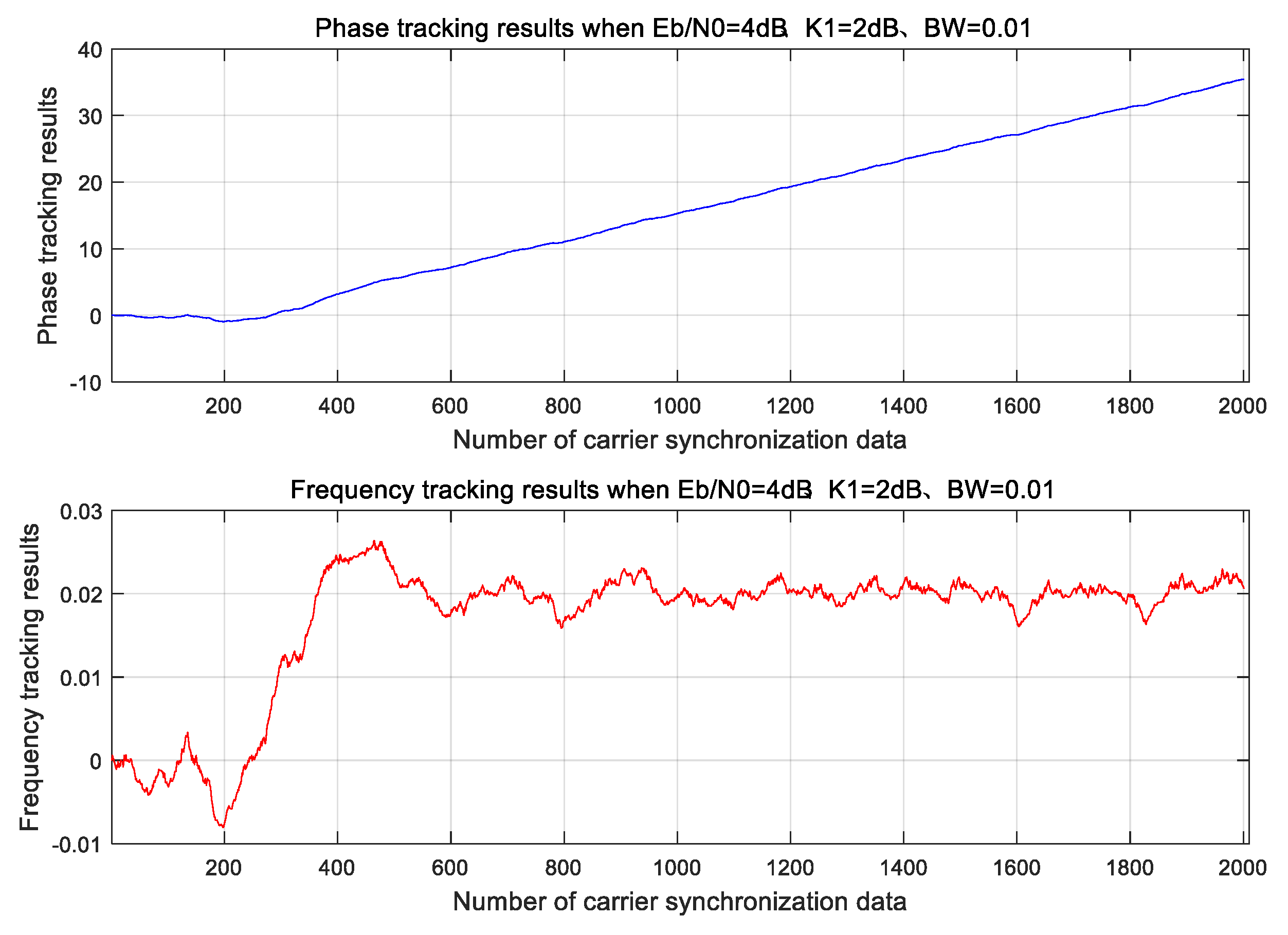
The simulation results for the lock-in curve after applying the bi-directional adaptive iterative carrier synchronization algorithm are shown in Figure 23, which shows the carrier lock curve with bi-directional adaptive synchronization. Compared to the traditional one-pass PLL method (which requires more than 400 symbols for synchronization), our method achieves full frame synchronization with just two iterations, using the actual data directly.
As shown in Figure 23, when using the bi-directional adaptive iterative carrier synchronization algorithm, the loop captures the carrier frequency with high precision after only two iterations, achieving a precise frequency lock at the required frequency point. In contrast, the traditional single-pass PLL requires more than 400 symbols to achieve synchronization. The iterative PLL, using actual data, quickly locks the carrier frequency, ensuring full data synchronization in just two iterations.
The performance of the proposed detection algorithm is evaluated through simulations using a dual SIC signal. The following simulation parameters were selected based on the project requirements: symbol rate of 5 Msps, initial maximum frequency offset of 50 kHz, SNR of 4 dB for the primary signal, a power ratio of 2 dB between the primary and secondary signals, BPSK modulation, a preamble length of 64 symbols, and a total data length of 2000 symbols. The simulation was conducted on 200,000 burst signals, with random initial frequency offsets and phases for each burst signal, and a maximum relative frequency deviation of 0.01.
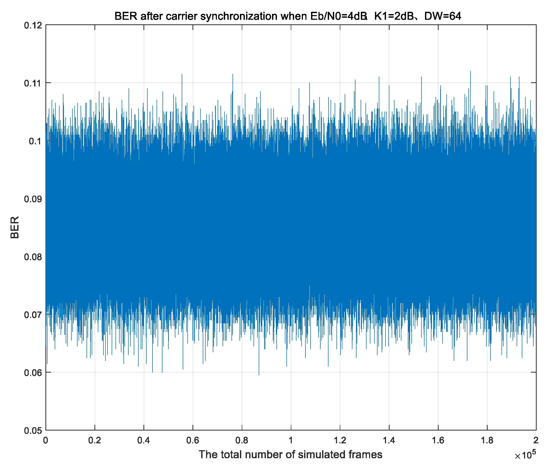
Figures show the frame error rate (FER) performance with and without pre-offset for the dual-signal case: Figure 24 illustrates the frame error rate without pre-frequency offset, showing higher error rates under the given conditions. Figure 25 presents the frame error rate with a pre-frequency offset, showing a notable improvement in detection accuracy.
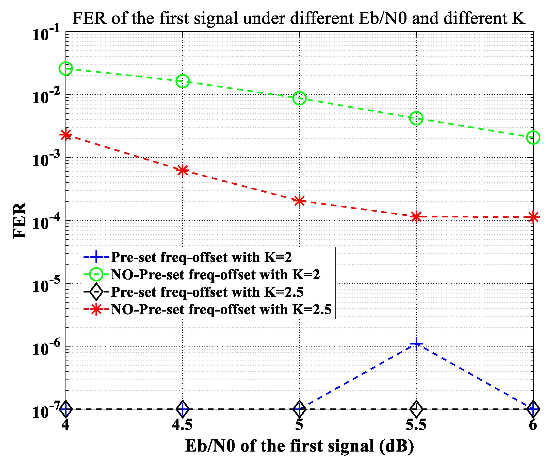
The simulation results demonstrate that the proposed pre-offset and bi-directional adaptive iterative carrier synchronization technique significantly enhances burst signal detection performance with minimal overhead in the burst preamble. When compared to the case without pre-frequency offset, the frame error rate for dual signals is notably reduced after pre-frequency offset is applied. Specifically, under the simulation conditions of an SNR of 4 dB for the primary signal and a 2 dB power ratio between the primary and secondary signals, the frame error rate decreases from 0.016% to 0.0005% when pre-frequency offset is used. A comparative simulation as shown in Figure 26 was conducted for the above algorithm with 500,000 burst signals. The frame error rate (FER) was compared under the following conditions: for a single signal with Eb/N0 ranging from 4 to 8 dB, and for two superimposed signals with power ratios of 2 dB and 2.5 dB. The simulations evaluated both cases with and without frequency pre-setting, demonstrating the stability of the algorithm.

5. Conclusions

This paper begins by introducing the fundamental principles of beam-hopping satellite communication systems and analyzing the challenges associated with enhancing uplink capacity. To address this, the NOMA technology based on SIC is incorporated into the system, aiming to improve the uplink multiple access capacity of beam-hopping satellite communication.
Theoretical analysis is conducted to evaluate the BER performance of the NOMA system utilizing SIC technology, and the theoretical results are validated through simulations, demonstrating the accuracy of the analysis. Additionally, in response to the challenge of low detection probability encountered when traditional carrier synchronization methods are employed in NOMA systems, a novel approach combining pre-configured frequency offset with bi-directional adaptive iterative carrier synchronization is proposed. Furthermore, a high-efficiency transmission burst structure and capture method are designed and optimized.
Simulation results demonstrate that the proposed method not only relaxes the power ratio requirement between the primary and secondary signals but also improves the capture probability of the primary signal. These findings highlight the promising potential for practical applications of this method in engineering.

Author Contributions

Conceptualization, T.H. and S.Z.; methodology, F.G.; software, T.H.; validation, T.H., S.Z. and F.G.; formal analysis, T.H.; investigation, T.H.; resources, T.H.; data curation, M.H.; writing—original draft preparation, T.H.; writing—review and editing, M.H. and R.L.; visualization, M.H.; supervision, M.H.; project administration, T.H.; funding acquisition, T.H. and Y.F. All authors have read and agreed to the published version of the manuscript.

Funding

This research was funded by the National Key R&D Program of China (Grant No. Y23-WYHXJS-07), the National Key R&D Program of China during the 14th Five-Year Plan Period (Grant No. 3050406), and the National Defense Basic Research Program (Grant No. 2022-JCJQ-JJ-0655).

Data Availability Statement

The original contributions presented in this study are included in the article. Further inquiries can be directed to the corresponding author.

Conflicts of Interest

The authors declare no conflicts of interest.

References

  1. Kodheli, O.; Lagunas, E.; Maturo, N.; Sharma, S.K.; Shankar, B.; Montoya, J.F.M.; Duncan, J.C.M.; Spano, D.; Chatzinotas, S.; Kisseleff, S.; et al. Satellite Communications in the New Space Era: A Survey and Future Challenges. IEEE Commun. Surv. Tutor. 2020, 23, 70–109. [Google Scholar] [CrossRef]
  2. Yahia, O.B.; Garroussi, Z.; Bélanger, O.; Sanso, B.; Frigon, J.-F.; Martel, S.; Lesage-Landry, A.; Kurt, G.K. Evolution of High-Throughput Satellite Systems: A Vision of Programmable Regenerative Payload. IEEE Commun. Surv. Tutor. 2024, 27, 1565–1597. [Google Scholar]
  3. Hui, T.; Zhang, J.; Liu, M. Research on Key Technology of New Generation High Throughput Satellite Communication System. Space Electron. Technol. 2021, 18, 10–15. [Google Scholar]
  4. Hui, T.; Zhai, S.; Zhang, Z.; Liu, C.; Gong, X.; Ni, Z.; Yang, K. A Fast and High-Precision Satellite-Ground Synchronization Technology in Satellite Beam Hopping Communication. Space Sci. Technol. 2024, 4, 0159. [Google Scholar] [CrossRef]
  5. ETSI EN 302 307-2 V1.2.1; Digital Video Broadcasting (DVB); Second Generation Framing Structure, Channel Coding, and Modulation Systems for Broadcasting, Interactive Services, News Gathering and Other Broadband Satellite Applications; Part 2: DVB-S2 Extensions (DVB-S2X). German Society for Standardization: Berlin, Germany, 2020.
  6. Gong, X.F. Research on Burst Demodulation Technology of Low Signal-to-Noise Ratio QPSK in Satellite Communication. Ph.D. Thesis, China Academy of Space Technology, Beijing, China, 2011. (In Chinese). [Google Scholar]
  7. Zhai, S.; Hui, T.; Gong, X.; Zhang, Z.; Gao, X.; Yang, K. High-Performance Receiving and Processing Technology in Satellite Beam Hopping Communication. J. Syst. Eng. Electron. 2024, 35, 815–828. [Google Scholar] [CrossRef]
  8. Benjebbour, A.; Saito, Y.; Kishiyama, Y.; Li, A.; Harada, A.; Nakamura, T. Concept and Practical Considerations of Non-Orthogonal Multiple Access (NOMA) for Future Radio Access. In Proceedings of the International Symposium Intelligent Signal Processing and Communication Systems, Naha, Japan, 12–15 November 2013; pp. 770–774. [Google Scholar]
  9. Wang, Q.; Xu, S.; Yan, X.; Wu, H.-C.; Wu, Y. Novel Efficient Multiwavelet-Based Modulation for Downlink NOMA Systems. IEEE Wirel. Commun. Lett. 2021, 10, 1242–1246. [Google Scholar] [CrossRef]
  10. Wang, G.; Zhao, Z.-J. Low Complexity Successive Signal Detection Algorithm in NOMA System. J. Signal Process. 2019, 35, 26–31. [Google Scholar]
  11. Casini, E.; Gaudenzi, R.D.; Ginesi, A. DVB-S2 Modem Algorithms Design and Performance Over Typical Satellite Channels. Int. J. Satell. Commun. Netw. 2004, 22, 281–318. [Google Scholar] [CrossRef]
  12. Skog, I.; Handel, P. Synchronization by Two-Way Message Exchanges: Cramer-Rao Bounds, Approximate Maximum Likelihood, and Offshore Submarine Positioning. IEEE Trans. Signal Process. 2010, 58, 2351–2362. [Google Scholar] [CrossRef]
  13. D’Andrea, A.N.; Mengali, U.; Reggiannini, R. The Modified Cramer-Rao Bound and Its Application to Synchronization Problems. IEEE Trans. Commun. 1994, 42, 1391–1399. [Google Scholar] [CrossRef]
  14. Valles, E.L.; Wesel, R.D.; Villasenor, J.D.; Jones, C.R.; Simon, M. Pilotless Carrier Phase-Synchronization via LDPC Code Feedback. In Proceedings of the 2010–Milcom 2010 Military Communications Conference, San Jose, CA, USA, 31 October–3 November 2010. [Google Scholar]
  15. Mengali, U.; Morelli, M. Data-Aided Frequency Estimation for Burst Digital Transmission. IEEE Trans. Commun. 1997, 45, 23–25. [Google Scholar] [CrossRef]
  16. Wang, C.H.; Gao, F. A Coherent Demodulation Method for Short Burst Communication Systems. In Proceedings of the IEEE 8th Joint International Information Technology and Artificial Intelligence Conference (ITAIC), Chongqing, China, 24–26 May 2019. [Google Scholar] [CrossRef]
  17. Rife, D.C.; Boorstyn, R. Single-Tone Parameter Estimation from Discrete-Time Observation. IEEE Trans. Inf. Theory 1974, 20, 591–598. [Google Scholar]
  18. Calvo, P.M.; Sevillano, J.F.; Velez, I.; Irizar, A. Enhanced Implementation of Blind Carrier Frequency Estimators for QPSK Satellite Receivers at Low SNR. IEEE Trans. Consum. Electron. 2005, 51, 442–448. [Google Scholar] [CrossRef]
  19. Gong, C.; Zhang, B.N.; Guo, D.S. A Quick and Accurate Union Carrier Parameter Estimation Algorithm Based on FFT. Acta Electron. Sin. 2010, 38, 766–770. [Google Scholar]
  20. Li, S.Y. Research on High-Efficient Receiver Synchronization Techniques in Burst Communication Systems. Ph.D. Thesis, Xidian University, Xi’an, China, 2018. (In Chinese). [Google Scholar]
  21. López-Salcedo, J.A.; Peral-Rosado, J.A.D.; Seco-Granados, G. Survey on Robust Carrier Tracking Techniques. IEEE Commun. Surv. Tutor. 2014, 16, 670–688. [Google Scholar] [CrossRef]
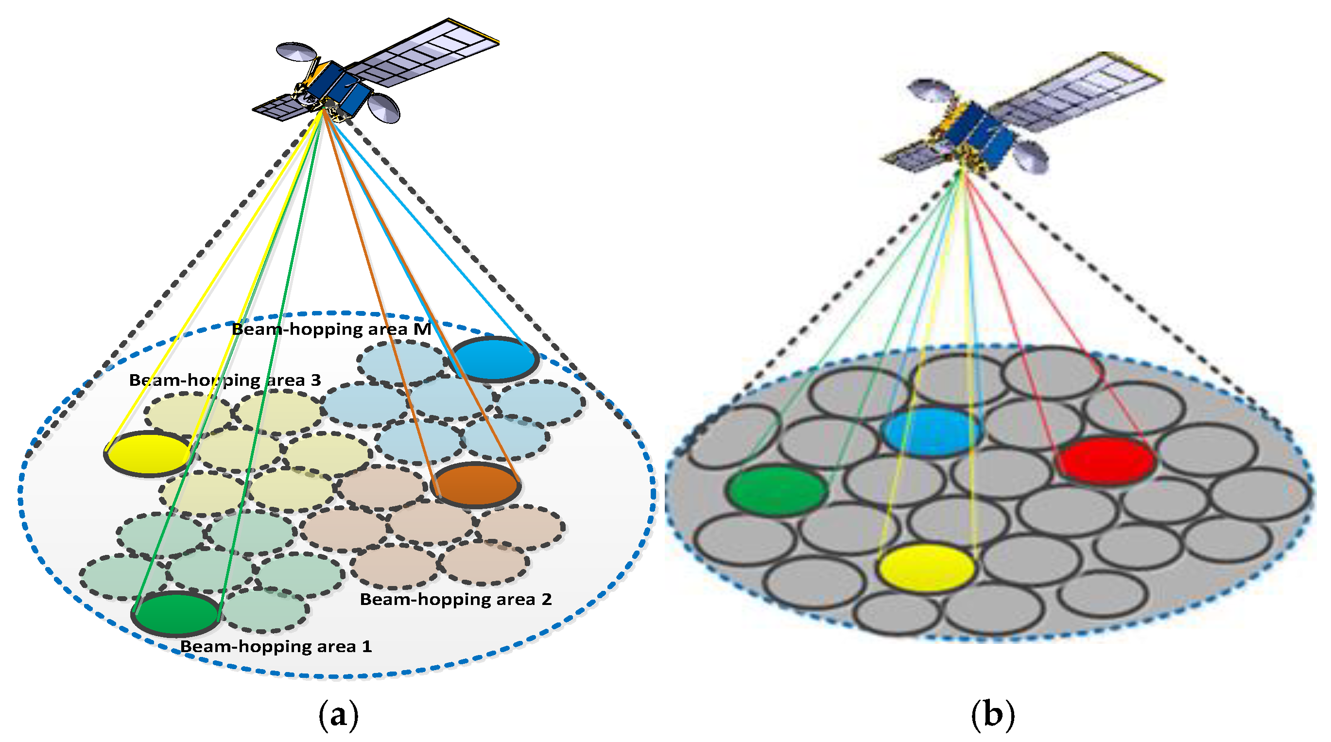
Figure 1. Coverage illustration of two types of beam-hopping techniques (a) Fixed Beam Pointing Beam-Hopping; (b) Dynamically Steerable Beam-Hopping.
Electronics 14 03578 g001
Figure 2. Simplified block diagram of a regenerative beam-hopping payload.
Electronics 14 03578 g002
Figure 3. Basic Reception Principle of SIC-Based Multi-Signal Processing.
Electronics 14 03578 g003
Figure 4. Power-Domain NOMA Scheme.
Electronics 14 03578 g004
Figure 5. Amplitude characteristics when considering the phase change in the dual signal.
Electronics 14 03578 g005
Figure 6. Amplitude characteristics when considering the phase change in the three signals.
Electronics 14 03578 g006
Figure 7. Closed-Loop Carrier Synchronization Architecture.
Electronics 14 03578 g007
Figure 8. Open-Loop Frequency Estimation Architecture.
Electronics 14 03578 g008
Figure 9. Hybrid Carrier Synchronization Structure.
Electronics 14 03578 g009
Figure 10. Three-Signal System with Pre-Configured Frequency Offsets.
Electronics 14 03578 g010
Figure 11. Multi-Signal Reception and Processing Flow.
Electronics 14 03578 g011
Figure 12. Phase Model of Second-Order Digital PLL.
Electronics 14 03578 g012
Figure 13. Bi-Directional Adaptive PLL Synchronization Architecture.
Electronics 14 03578 g013
Figure 14. Traditional Burst Frame Structure.
Electronics 14 03578 g014
Figure 15. Optimized Burst Frame Structure.
Electronics 14 03578 g015
Figure 16. Theoretical BER of First Signal Under Different Power Ratios ( K 1 = 20 log 10 ( α ) ) .
Electronics 14 03578 g016
Figure 17. Comparison Between Theoretical and Simulated BER of First Signal.
Electronics 14 03578 g017
Figure 18. Simulated Average BER Under Uniform Initial Phase Distribution.
Electronics 14 03578 g018
Figure 19. Theoretical BER of the First Signal under Various Power Ratios ( K 1 = 20 log 10 ( β ) ,   K 2 = 20 log 10 ( γ ) .
Electronics 14 03578 g019
Figure 20. Comparison of Theoretical and Simulated BER for the First Signal.
Electronics 14 03578 g020
Figure 21. Carrier Tracking with High SNR and Loop Bandwidth = 0.02.
Electronics 14 03578 g021
Figure 22. Carrier Tracking with Low SNR and Loop Bandwidth = 0.005.
Electronics 14 03578 g022
Figure 23. Carrier Lock Curve with Bi-Directional Adaptive Synchronization.
Electronics 14 03578 g023
Figure 24. Frame Error Rate without Pre-Frequency Offset.
Electronics 14 03578 g024
Figure 25. Frame Error Rate with Pre-Frequency Offset.
Electronics 14 03578 g025
Figure 26. Frame Error Rate Comparison for Single and Superimposed Signals with and without Frequency Pre-Setting.
Electronics 14 03578 g026
Table 1. A comparison table between MF-TDMA and NOMA-SIC.
FeatureMF-TDMANOMA-SIC
Spectral EfficiencyLower. Resources (time and frequency slots) are orthogonal, underutilization.Higher. Superimposes multiple users on the same time-frequency resource, serving more users simultaneously and improving overall cell throughput.
LatencyPredictable and Fixed.Variable and Complex.
ComplexityLow (Transmitter)/Moderate (Receiver). Simple transmission; complexity is centralized in the gateway/scheduler for resource allocation.High (Transmitter)/Very High (Receiver). Requires sophisticated power allocation algorithms at the transmitter and complex SIC decoding at the receiver.
Table 2. Error at Eb/N0 = 6 dB for NOMA-BPSK Monte Carlo Simulations with Different Numbers of Trials (N).
IndexMonte Carlo Trials (N)VarianceStandard Deviation
110240.03500.0011
21280.03480.0031
3320.03600.0064
Table 3. Simulation Parameters for SIC with Two Superimposed Signals.
Simulation ParameterValue/Setting
Symbol rate5 Msps
Maximum initial frequency offset50 kHz (relative offset = 0.01)
SNR of the first signal4 dB
Power ratio between first and second signal2 dB
ModulationBPSK
Data length2000 symbols
Disclaimer/Publisher’s Note: The statements, opinions and data contained in all publications are solely those of the individual author(s) and contributor(s) and not of MDPI and/or the editor(s). MDPI and/or the editor(s) disclaim responsibility for any injury to people or property resulting from any ideas, methods, instructions or products referred to in the content.