Abstract
This study presents the design of an optimal Electric Resonant Coupling Wireless Power Transfer (ER-WPT) coupler intended for multiple-input multiple-output (MIMO) systems. The proposed coupler features a hexagonal-stacked structure optimized for electric field coupling and consists of three transmitters and one receiver. Analysis of the electromagnetic characteristics in this 3-to-1 configuration can be extended to larger arrays. Theoretical analysis based on a practical equivalent circuit (PEC) model, which incorporates loss elements from measurement, is validated through comparison with 3D full-wave simulations and experimental results. Across three representative receiver positions, the summed transmission coefficient of the MISO structure reaches up to 0.90, while the PEC model agrees with measurements within a maximum deviation of 0.09, confirming high accuracy. Furthermore, the proposed structure demonstrates stable resonance characteristics near 6.78 MHz with reduced frequency shifts under different receiver positions. The key contributions of this work are the proposal of an efficient hexagonal-stacked MISO ER-WPT coupler and a validated equivalent circuit modeling approach that reflects real-world losses, providing a reliable basis for future multi-transmitter/multi-receiver Wireless Power Transfer systems.
1. Introduction
Wireless Power Transfer (WPT) technology is regarded as an essential method to ensure continuous power supply for numerous IoT devices, such as smartphones and wearable devices. Thanks to the advantage of eliminating the need for physical power cables, WPT has attracted significant attention as a key technology that enhances user experience and overcomes constraints related to charging time and location across various environments, including smart homes, smart cities, industrial automation, and autonomous vehicles.
WPT methods can be categorized into Magnetic Resonant Wireless Power Transfer (MR-WPT), which utilizes resonant coupling via magnetic fields, and Electric Resonant Wireless Power Transfer (ER-WPT), which employs resonant coupling via electric fields [1]. These WPT methods are fundamentally based on single-input single-output (SISO) structures, which suffer from spatial limitations in charging freedom [2]. To overcome this limitation and to achieve greater freedom in charging positions and enable multiple simultaneous charging, multiple-input multiple-output (MIMO) WPT technology is essential. Accordingly, various approaches have been proposed to extend the area by arranging multiple coils [3,4]. In fact, MIMO WPT systems have been reported to improve received power and efficiency by adding multiple transmitter coils [5,6,7], and arranging transmitter coils larger than receiver coils is known to enhance tolerance against misalignment between transmitter and receiver [8]. Consequently, interest in multi-transmitter WPT systems is increasing.
However, implementing multi-transmitter and multi-receiver WPT systems introduces challenges such as impedance variations and resonance frequency shifts due to cross-coupling among multiple coils, which can degrade output stability [9,10,11,12]. In particular, problems arise from coil misalignment, limited system bandwidth, and frequency mismatches between transmitter and receiver, leading to power loss [13,14,15,16,17]. To improve system stability and efficiency, real-time detection and compensation strategies for dynamically changing coupling characteristics during operation are necessary. Nevertheless, theoretical analyses on the electromagnetic characteristic variations of such couplers remain insufficient [18,19,20,21,22]. While previous studies on MR-WPT systems have applied sensors to mitigate efficiency degradation caused by external objects or positional changes, in the ER-WPT field, only attempts to detect receiver position changes through symmetry evaluation of capacitance matrices have been proposed. Ultimately, equivalent circuit analysis is indispensable to closely examine coupling changes arising from electromagnetic characteristic variations in multi-structure couplers [23,24]. Through this approach, design guidelines can be obtained to ensure uniform performance in multi-transmitter/multi-receiver systems.
This study designs an optimal multiple-input single-output (MISO) ER-WPT coupler for MIMO. As shown in Figure 1, the proposed coupler features a hexagonal-stacked structure favorable for electric field coupling, offering clearer advantages over square or rectangular geometries in terms of coupling uniformity and scalability to honeycomb MISO arrays. The ER-WPT coupler consists of three transmitters and one receiver. Analysis of the electromagnetic characteristics in the 3-to-1 structure can be dominantly applied to larger arrays. In electric field coupling, a greater overlapping area between conductor plates increases coupling capacitance, thus improving efficiency. The hexagonal structure is advantageous when arranging multiple transmitter couplers in a honeycomb pattern to ensure sufficient coupling. It also enables dense coverage of the transmitter area, minimizing null points [25]. The theoretical analysis based on the equivalent circuit model of the proposed design is compared with 3D full-wave analysis and measurement results. Representative electromagnetic characteristic analyses are performed for three receiver positions. Additionally, a practical equivalent circuit model (PEC) that reflects loss elements occurring in the measurement model is proposed with high accuracy.
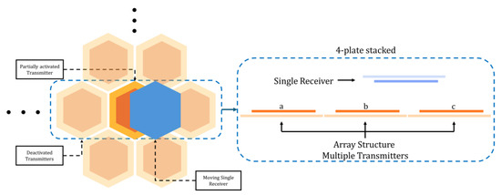
Figure 1.
Hexagonal MISO ER-WPT coupler proposed in this study.
The key contributions of this study can be summarized as follows:
- A hexagonal-stacked ER-WPT coupler structure optimized for MIMO WPT is proposed.
- Practical usefulness is demonstrated by proposing a highly accurate equivalent circuit model that accounts for losses.
2. Theoretical Analysis of Hexagonal MISO ER-WPT Coupler
2.1. PEC Modeling and Capacitance Analysis
Figure 2 illustrates a typical stacked ER-WPT system configuration, consisting of multiple layers of electrically resonant metal plates, generally arranged in a vertical stack of four plates. These metal plates are electrically connected within both the transmitter and receiver units. The DC voltage source applied at the transmitter is converted to AC voltage via an inverter. Subsequently, the signal passes through an impedance matching network composed of LC elements, designed to maximize electric field resonance and coupling at a specific frequency. This impedance matching circuit together with the plate structure constitutes the coupler in WPT systems. To achieve high power transfer efficiency, analyzing the electromagnetic characteristics of the coupler is essential. This study focuses on designing such a coupler.
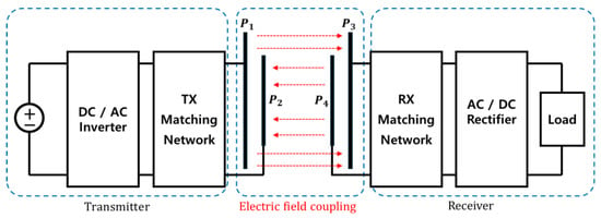
Figure 2.
Topology of stacked ER-WPT.
In a typical two-port network, the equivalent circuit representing electric field coupling can be referenced as shown in [26]. To express the coupler’s self-capacitance and mutual capacitance in the connected network, a Pi-model is commonly adopted, which applies equally to both parallel and stacked structures. A four-port network representation, as shown in Figure 3a of [26], can be extended as in Figure 3, here. However, theoretical analysis is complicated due to the indistinct separation of mutual coupling elements in the equivalent circuit.
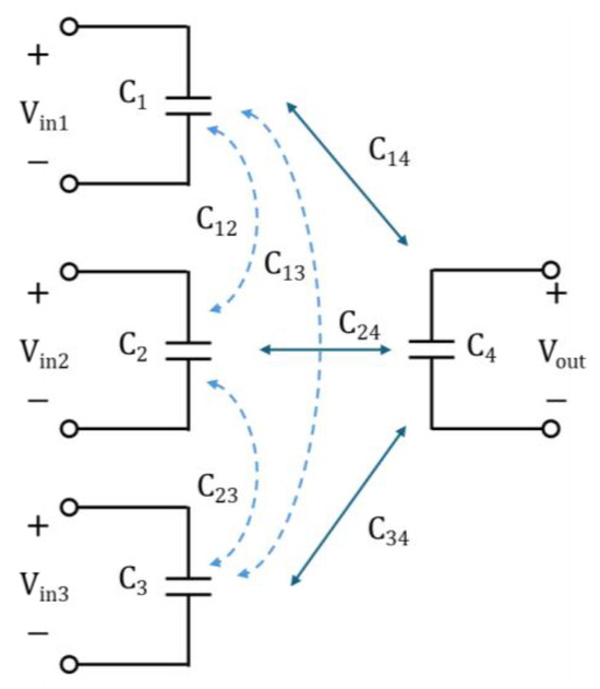
Figure 3.
Mutual coupling of MISO ER-WPT coupler.
In Figure 3, each mutual coupling element is represented by a Pi-model-connected circuit, as defined in Figure 4, which includes the impedance matching circuits proposed in this study. The model corresponds to a configuration with three transmitters and one receiver, applicable not only to a 3-to-1 structure but also to larger scales. Here, (where i is the port number) represents the self-capacitance of each coupler, and denotes the mutual capacitance between couplers. Because the self-capacitance forms an equivalent circuit with multiple ports via the Pi-model, calculations of multiple mutual capacitances are necessary.
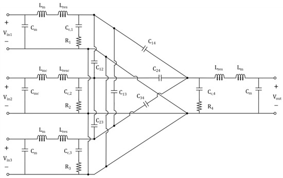
Figure 4.
PEC of MISO ER-WPT coupler.
Considering this circuit form, the self-capacitance for each port can be defined as shown in Equation (1).
Self-capacitance and mutual capacitance are calculated based on numerous capacitances formed between the plates. The diagram in Figure 5 illustrates capacitances formed among eight plates. According to the fundamental capacitance calculation formulas [27], the four-port network capacitances are computed as in Equation (2).
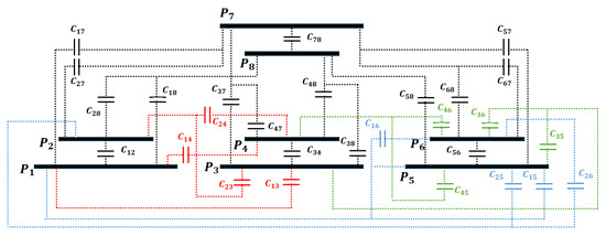
Figure 5.
Capacitance configuration diagram of MISO-stacked ER-WPT plates.
2.2. S-Parameter Calculation and Parameter Extraction
The transmission matrix of the Partitional Circuit Network (PCN) in the previously defined PEC model can be expressed as shown in Table 1. To convert this into S-parameters, a method that simplifies complex equations by substitution is provided in [24]. Following this approach, by expressing the matrix elements as t, the components constituting the S-parameters can be summarized as follows.

Table 1.
Components of the S-parameters for each PCN.
In this paper’s equivalent circuit, Port 1 (input voltage Vin1) is designated as Type A1, Port 2 as Type A2, Port 3 as Type A3, and the receiver Port 4 as Type A’. Circuits including mutual coupling elements are classified according to port numbers. For example, the network coupling Ports 1 and 2 are defined as Type B. This classification is applied to define the overall four-port S-parameter matrix.
Since there are four ports, six combinations of two-port subnetworks exist, each represented by a 2 × 2 matrix. These defined S-parameters, as shown in Equations (4) and (5), combine to form the full 4 × 4 S-parameter matrix.
The theoretical analysis method of the proposed equivalent circuit model applies the parameters summarized in Table 2 and Table 3. The impedance matching circuit values and intrinsic capacitance of the coupler are listed. Equivalent parameters are calculated based on the inherent LC characteristics of the coupler structure designed via 3D full-wave analysis at 6.78 MHz. However, practical adjustments were necessary due to the limited availability of passive components for physical fabrication. In addition, the loss components were extracted by fitting the measured S-parameters to the circuit response. Specifically, the resistance values (R) were determined by matching the measured insertion loss and transmission coefficient magnitudes, while inductance deviations (ΔL) were adjusted to align the PEC resonance frequency with the experimental results. These modifications reflect the tolerance and parasitic effects of the fabricated components, ensuring that the PEC model accurately represents the practical losses observed in measurement.

Table 2.
Equivalent parameters of fabricated SISO-stacked ER-WPT coupler.

Table 3.
Equivalent parameters of fabricated MISO-stacked ER-WPT coupler.
This study distinguishes between SISO and MISO structures, with corresponding parameters for each. The MISO structure uses the same receiver as the SISO structure. Ideally, impedance matching would be re-optimized for the 3-to-1 structure, but optimal matching parameters vary with receiver position. For practical reasons, variable matching depending on receiver position is not feasible; thus, the SISO coupler receiver parameters are applied for uniform characteristics and loss analysis.
3. Design of Hexagonal MISO-Stacked ER-WPT Coupler
The MISO ER-WPT coupler is designed to maximize electric field coupling efficiency. Coupling strength increases with the overlapping area of corresponding metal plates in transmitter and receiver units. For MIMO systems, the coupler must ensure sufficient overlap regardless of receiver position and maintain uniform electromagnetic characteristics under arbitrary misalignment. The hexagonal plate structure satisfies these requirements.
Analysis of this basic unit can be dominantly extended to larger array structures. This section details the design of SISO and 3-to-1 MISO hexagonal-stacked ER-WPT couplers. Transmission characteristics are observed for three representative receiver positions in the MISO structure: aligned with a single transmitter, positioned between two transmitters, and located at the center of three transmitters. These results are compared with PEC and measurement data.
3.1. Three-Dimensional Full-Wave Analysis Models
Figure 6 shows the proposed single coupler model of the hexagonal ER-WPT, designed and analyzed using Ansys HFSS R2021. Taconic RF-35 substrates are used, with copper sheets processed on both sides to form the hexagonal plates. The back plate is located on the substrate’s bottom side, and the front plate on the top. An optimal plate ratio exists to maximize mutual capacitance in stacked structures [23]. In the proposed design, the front plate’s side length is 70% of the back plate’s. Matching circuit traces connect to each plate via vias through the dielectric substrate. Figure 6a shows the SISO coupler model, where transmitter and receiver front plates face each other. The matching circuit on the substrate uses copper traces 0.3 mm wide, with SMA connectors implemented for measurements. The same applies to the MISO coupler shown in Figure 6b, where three hexagonal ER-WPT couplers are arranged in a triangular layout. One coupler requires a longer trace and exhibits slightly different impedance characteristics. The receiver uses the SISO coupler model unchanged. Detailed design parameters are listed in Table 4.
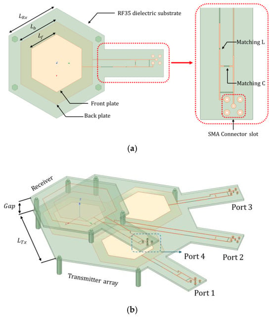
Figure 6.
Three-dimensional full-wave analysis models. (a) SISO coupler; (b) MISO coupler.

Table 4.
Specifications of hexagonal-stacked ER-WPT coupler.
Analysis of the 3-to-1 structure’s electromagnetic characteristics for three representative receiver positions, as illustrated in Figure 7, provides dominant features applicable to further array expansion. The longer trace coupler among transmitters exhibits slightly different impedance, requiring separate analysis of coupling with Tx B and Tx C. Table 5 summarizes the measurement scenarios divided into three cases. Case O includes Rx aligned with Tx B or Tx C individually, with only the corresponding Tx active. Cases M and C involve multiple Tx units active due to non-alignment with a single Tx, requiring observation of couplings with Tx B and Tx C. Tx A and Tx C have identical electromagnetic properties and are collectively represented by Tx C.
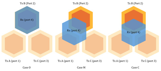
Figure 7.
Representative analysis cases.

Table 5.
Classification of measurement scenarios into three cases.
3.2. Fabricated Models
Based on the specifications from Section 3.1, the fabricated models shown in Figure 8 were produced. Passive components corresponding to equivalent parameters derived from 3D full-wave analysis were used, including unavoidable loss elements. Achieving the optimal component values at 6.78 MHz is generally difficult, so some loss is tolerated and reflected in the PEC for accurate analysis.
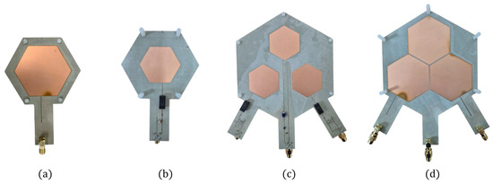
Figure 8.
Fabricated models of Hexagonal ER-WPT coupler. (a) Top view of SISO coupler; (b) bottom view of SISO coupler; (c) top view of MISO Tx coupler; (d) bottom view of MISO Tx coupler.
Figure 8a,b depicts the hexagonal SISO ER-WPT model, with the same receiver coupler applied to the MISO model. The assembly was supported by PVC structures and measured as shown in Figure 9. For the MISO coupler, measurements were performed by changing transmitter ports using a vector network analyzer (T3VNA3200, Teledyne LeCroy, Chestnut Ridge, NY, USA).
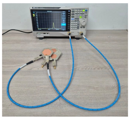
Figure 9.
Experimental setup.
4. Results and Discussion
This section compares the results of theoretical analysis, HFSS simulations, and measurements for each case. For Case O, measurements were conducted with the receiver (Rx) aligned to Tx B and Tx C, respectively. For the other cases, coupling between Tx B, Tx C, and Rx positions was observed. Losses observed in the measurements were incorporated into the PEC model to achieve high accuracy.
Figure 10 shows the transmission coefficient results for the SISO coupler obtained via the three methods. The measurement peak was 0.63, the HFSS peak was 0.66, and the PEC peak was 0.62, indicating generally consistent results. The measurement and PEC results matched within a 0.33% error. The overall lower peak values are attributed to the frequency characteristics of the components and inherent coupler losses. PEC analysis indicated approximately 8 Ω of resistive components and a 1 μH deviation in inductors, causing resonance frequency shifts and transmission loss.
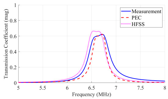
Figure 10.
Comparison of transmission coefficients in hexagonal SISO ER-WPT couplers.
Figure 11 presents transmission coefficients for the MISO coupler at three receiver positions analyzed by the three methods. S42 and S43 denote the S-parameters between respective ports; for example, S42 corresponds to the S-parameter between Tx B and the receiver (Port 4).
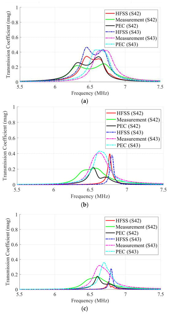
Figure 11.
Comparison of transmission coefficients (S-parameter) in hexagonal MISO ER-WPT couplers. (a) Case O; (b) Case M; (c) Case C.
In Case O, HFSS showed a peak of 0.47 when Rx was aligned with Tx C, differing by 0.04 from the PEC peak of 0.43. In Case M, PEC and measurement peaks matched closely with only a 0.02 difference, though HFSS exhibited larger discrepancies, likely due to unmodeled measurement errors. Case C showed a maximum HFSS value of 0.38, with the PEC result differing by about 0.02. Overall, PEC matched the measurement results within a transmission coefficient difference ranging from 0.01 to 0.09.
In addition to transmission coefficients, the reflection coefficients of Tx A, Tx B, Tx C, and the Rx were analyzed, as shown in Figure 12. These results were obtained from electromagnetic simulations based on the PEC model, in which measured loss elements were incorporated to reflect practical conditions. Across all three cases, clear resonance behavior is observed near 6.78 MHz. In Case O, the Tx aligned with the receiver shows the deepest return loss, while the other Tx ports exhibit weaker resonance. In Case M, two adjacent transmitters coupled to the receiver both display pronounced dips, with a slight frequency splitting due to mutual interaction. In Case C, all three transmitters show nearly identical resonance dips, and the receiver resonates at the same frequency, confirming uniform coupling to multiple transmitters.
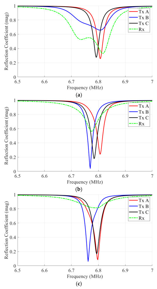
Figure 12.
Comparison of reflection coefficients (S-parameter) in hexagonal MISO ER-WPT couplers. (a) Case O; (b) Case M; (c) Case C.
These reflection characteristics indicate possible strategies for selective transmitter activation. For example, in Case O, activating only the transmitter aligned with the receiver would maximize efficiency. In Case M, activating the two adjacent transmitters could enhance cooperative coupling, and in Case C, simultaneous activation of all transmitters could provide robust and balanced power transfer. While such selective activation was not implemented in this work, the results suggest that the proposed hexagonal-stacked structure supports these scenarios and could further improve multi-transmitter WPT performance in practice.
Table 6 summarizes these case results, demonstrating the MISO coupler’s effectiveness under misalignment. When the receiver is positioned centrally among three transmitters, the overlapping area with each single transmitter is minimal. Nevertheless, coupling with all three transmitters confirms the coupler’s effectiveness in power transfer scenarios. However, summing transmission coefficients alone does not numerically prove equivalent compensation in power transfer efficiency.

Table 6.
Total transmissions coefficient by each case.
In Case O, coupling with other transmitters is excluded, so the total value equals the peak value. In Case M, where the receiver lies between two transmitters, S41 is excluded from the total. In Case C, coupling with all three transmitters is summed. The results indicate higher effectiveness in the 3-to-1 configuration of Case C than in single transmitter–receiver alignment.
5. Conclusions
This paper analyzed the electromagnetic characteristics of a 3-to-1 hexagonal MISO-stacked ER-WPT coupler. The model was theoretically examined using a PEC model of a four-port ER-WPT coupler. Electromagnetic characteristics were evaluated for three receiver position scenarios and compared with HFSS simulations and measurements. The summation of transmission coefficients in each case demonstrated the efficiency of multiple-transmitter configurations. The PEC model showed high agreement with measurements, with maximum discrepancies within 0.09. This suggests that the proposed modeling approach, which accounts for losses and frequency variations, can be effectively applied to the design of multi-transmitter environments. However, addressing losses remains a challenge for future work. The impedance matching method based on passive components has several limitations. Future research will focus on expanding the model for applications in IoT devices and UAV wireless charging.
Author Contributions
Conceptualization, S.-W.P. and H.-G.B.; methodology, S.-W.P.; software, H.-G.B.; validation, H.-G.B.; formal analysis, H.-G.B.; investigation, H.-G.B.; resources, S.-W.P.; data curation, H.-G.B.; writing—original draft preparation, H.-G.B.; writing—review and editing, H.-G.B.; visualization, H.-G.B.; supervision, S.-W.P.; project administration, S.-W.P.; funding acquisition, S.-W.P. All authors have read and agreed to the published version of the manuscript.
Funding
This work was supported by the Soonchunhyang University Research Fund.
Data Availability Statement
The raw data supporting the conclusions of this article will be made available by the authors upon request.
Conflicts of Interest
The authors declare no conflicts of interest.
References
- Jiang, J.; Meng, Z. Frequency Stability Analysis and Charging Area Expanding Optimal Design for Matrix Coupling Mechanism in Wireless Power Transfer System. Electronics 2024, 13, 1312. [Google Scholar] [CrossRef]
- Lin, C.-H.; Amir, M.; Tariq, M.; Shahvez, M.; Alamri, B.; Alahmadi, A.; Siddiqui, M.; Beig, A. Comprehensive Analysis of IPT v/s CPT for Wireless EV Charging and Effect of Capacitor Plate Shape and Foreign Particle on CPT. Processes 2021, 9, 1619. [Google Scholar] [CrossRef]
- Dai, X.; Jiang, J.-C.; Wu, J.-Q. Charging Area Determining and Power Enhancement Method for Multiexcitation Unit Configuration of Wirelessly Dynamic Charging EV System. IEEE Trans. Ind. Electron. 2019, 66, 4086–4096. [Google Scholar] [CrossRef]
- Jeon, S.-J.; Seo, D.-W. Coupling Coefficient Measurement Method with Simple Procedures Using a Two-Port Network Analyzer for a Multi-Coil WPT System. Energies 2019, 12, 3950. [Google Scholar] [CrossRef]
- Monti, G.; Che, W.; Wang, Q.; Costanzo, A.; Dionigi, M.; Mastri, F.; Mongiardo, M.; Perfetti, R.; Tarricone, L.; Chang, Y. Wireless Power Transfer with Three-Ports Networks: Optimal Analytical Solutions. IEEE Trans. Circuits Syst. I Regul. Pap. 2017, 64, 494–503. [Google Scholar] [CrossRef]
- Pacini, A.; Costanzo, A.; Aldhaher, S.; Mitcheson, P.D. Load- and Position-Independent Moving MHz WPT System Based on GaN-Distributed Current Sources. IEEE Trans. Microw. Theory Tech. 2017, 65, 5367–5376. [Google Scholar] [CrossRef]
- Monti, G.; Mongiardo, M.; Minnaert, B.; Costanzo, A.; Tarricone, L. Multiple Input Multiple Output Resonant Inductive WPT Link: Optimal Terminations for Efficiency Maximization. Energies 2021, 14, 2194. [Google Scholar] [CrossRef]
- Huh, S.; Park, B.; Choi, S.; Shin, Y.; Kim, H.; Kim, J.; Park, J.; Park, D.; Ahn, S. Transmitter Coils Selection Method for Wireless Power Transfer System with Multiple Transmitter Coils and Single Receiver Coil. IEEE Trans. Power Electron. 2023, 38, 4092–4109. [Google Scholar] [CrossRef]
- Yoon, I.-J.; Ling, H. Investigation of Near-Field Wireless Power Transfer Under Multiple Transmitters. IEEE Antennas Wirel. Propag. Lett. 2011, 10, 662–665. [Google Scholar] [CrossRef]
- Lee, K.; Cho, D.-H. Diversity Analysis of Multiple Transmitters in Wireless Power Transfer System. IEEE Trans. Magn. 2013, 49, 2946–2952. [Google Scholar] [CrossRef]
- Cannon, B.L.; Hoburg, J.F.; Stancil, D.D.; Goldstein, S.C. Magnetic Resonant Coupling as a Potential Means for Wireless Power Transfer to Multiple Small Receivers. IEEE Trans. Power Electron. 2009, 24, 1819–1825. [Google Scholar] [CrossRef]
- Xu, Y.; Zhang, Y.; Wu, T. Wireless Power Transfer Efficiency Optimization Tracking Method Based on Full Current Mode Impedance Matching. Sensors 2024, 24, 2917. [Google Scholar] [CrossRef]
- Lu, Z.; Zhao, Y.; Liu, D. Adaptive Impedance Matching Scheme for Magnetic MIMO Wireless Power Transfer System. Electronics 2021, 10, 2788. [Google Scholar] [CrossRef]
- Lee, W.-T.; Kung, M.-L.; Lin, K.-H. π-Impedance Matching Circuit for Wireless Power Transfer Systems under Dynamic Load and Transfer Distance. In Proceedings of the 2020 IEEE International Symposium on Antennas and Propagation and North American Radio Science Meeting, Montreal, QC, Canada, 5 July 2020; pp. 1579–1580. [Google Scholar]
- Nguyen, M.Q.; Plesa, D.; Rao, S.; Chiao, J.-C. A Multi-Input and Multi-Output Wireless Energy Transfer System. In Proceedings of the 2014 IEEE MTT-S International Microwave Symposium (IMS2014), Tampa, FL, USA, 1–6 June 2014; pp. 1–3. [Google Scholar]
- Zhou, W.; Zhou, H.; Cui, X.; Zhou, F.; Tan, H.; Li, X.-Y. IMeP: Impedance Matching Enhanced Power-Delivered-to-Load Optimization for Magnetic MIMO Wireless Power Transfer System. ACM Trans. Sens. Netw. 2023, 19, 1–25. [Google Scholar] [CrossRef]
- Pahlavan, S.; Jafarabadi-Ashtiani, S.; Mirbozorgi, S.A. Maze-Based Scalable Wireless Power Transmission Experimental Arena for Freely Moving Small Animals Applications. IEEE Trans. Biomed. Circuits Syst. 2025, 19, 120–129. [Google Scholar] [CrossRef]
- Jiwariyavej, V.; Imura, T.; Hori, Y. Coupling Coefficients Estimation of Wireless Power Transfer System via Magnetic Resonance Coupling Using Information from Either Side of the System. IEEE J. Emerg. Sel. Top. Power Electron. 2015, 3, 191–200. [Google Scholar] [CrossRef]
- Liu, Z.; Li, T.; Li, S.; Mi, C.C. Advancements and Challenges in Wireless Power Transfer: A Comprehensive Review. Nexus 2024, 1, 100014. [Google Scholar] [CrossRef]
- Houran, M.A.; Yang, X.; Chen, W. Magnetically Coupled Resonance WPT: Review of Compensation Topologies, Resonator Structures with Misalignment, and EMI Diagnostics. Electronics 2018, 7, 296. [Google Scholar] [CrossRef]
- Dai, Z.; Sun, M.; Chen, H.; Ding, X.; Wang, H.; Zhai, Y.; Song, J.; Ye, S.; Zhang, M.; Zhang, X. Hybrid Wireless Power Transfer: A Review. Wirel. Power Transf. 2025, 12, e017. [Google Scholar] [CrossRef]
- Van Mulders, J.; Delabie, D.; Lecluyse, C.; Buyle, C.; Callebaut, G.; Van Der Perre, L.; De Strycker, L. Wireless Power Transfer: Systems, Circuits, Standards, and Use Cases. Sensors 2022, 22, 5573. [Google Scholar] [CrossRef]
- Xue, M.; Hou, H.; Li, L.; Guo, J.; Zhang, P.; Zhu, G. Analysis of the Electromagnetic Coupling Characteristics of Dual-Load Wireless Power Transmission Channels. Processes 2022, 10, 1931. [Google Scholar] [CrossRef]
- Hu, Y.; Dong, W.; Li, X.; Zhang, H.; Men, L. Active Regulation of Electromagnetic Force in Wireless Power Transfer Systems. Electronics 2024, 13, 1568. [Google Scholar] [CrossRef]
- Hyeong, N.; Han, S.-M.; Park, S.-W. Null-Power Point Analysis of Wireless Power Transfer Coupler and Improvement Method. In Proceedings of the 2024 16th International Conference on Information Technology and Electrical Engineering (ICITEE), Bali, Indonesia, 23–25 October 2024; pp. 120–124. [Google Scholar]
- Bae, H.; Park, S. Design of Four-Plate Parallel Dynamic Capacitive Wireless Power Transfer Coupler for Mobile Robot Wireless-Charging Applications. Appl. Sci. 2025, 15, 823. [Google Scholar] [CrossRef]
- Luo, B.; Mai, R.; Guo, L.; Wu, D.; He, Z. LC–CLC Compensation Topology for Capacitive Power Transfer System to Improve Misalignment Performance. IET Power Electron. 2019, 12, 2626–2633. [Google Scholar] [CrossRef]
Disclaimer/Publisher’s Note: The statements, opinions and data contained in all publications are solely those of the individual author(s) and contributor(s) and not of MDPI and/or the editor(s). MDPI and/or the editor(s) disclaim responsibility for any injury to people or property resulting from any ideas, methods, instructions or products referred to in the content. |
© 2025 by the authors. Licensee MDPI, Basel, Switzerland. This article is an open access article distributed under the terms and conditions of the Creative Commons Attribution (CC BY) license (https://creativecommons.org/licenses/by/4.0/).