1. Introduction
Electric vehicles (EVs) have emerged as a sustainable alternative to internal-combustion-engine vehicles, driven by growing environmental concerns and the global shift toward carbon neutrality. At the heart of EV operation lies the lithium-ion battery (LIB), which offers high energy density, rapid dynamic response, and long cycle life. However, the performance and reliability of LIBs degrade over time due to a complex interaction of electrical, thermal, and chemical processes during charge–discharge cycles and under varying environmental conditions [
1].
The inevitable degradation of battery capacity and power capability significantly impacts EV performance, reducing driving range, compromising safety, and increasing lifecycle costs. As fast charging technologies are increasingly adopted to improve user convenience, batteries are subjected to elevated electrical and thermal stresses that accelerate aging mechanisms such as lithium plating, electrolyte decomposition, and active material loss [
2]. These issues highlight the critical need for intelligent battery management strategies that can effectively extend battery lifespan without compromising performance. Recent advancements in battery modeling and estimation have demonstrated the potential of incorporating fractional-order models, adaptive filtering, and online parameter identification techniques to capture battery behavior more accurately under dynamic operating profiles. Moreover, multi-objective optimization frameworks have been proposed to balance charging time, thermal safety, and capacity fade by employing degradation-aware charging strategies.
Motivated by these developments, this study aims to explore advanced control and estimation approaches for enhancing the durability of LIBs in EVs. The proposed framework ultimately contributes to the development of health-aware, energy-efficient, and lifespan-optimized battery usage strategies. While extensive research has been devoted to improving battery lifetime through adaptive charging profiles and degradation-aware estimation methods, the role of power electronics—particularly the on-board charger (OBC)—is increasingly recognized as pivotal in realizing these strategies. The OBC serves as a bidirectional interface between the electric grid and the vehicle’s high-voltage battery system, typically incorporating both AC-DC and DC-DC stages, and is responsible not only for energy transfer but also for shaping the charging waveform, ripple current characteristics, and thermal behavior of the battery pack.
Recent advancements highlight that improper power decoupling, pulsating current injection, or poor thermal management at the OBC level can accelerate battery degradation, particularly under weak-grid or extreme high-frequency ripple conditions. To mitigate these effects, novel OBC architectures such as Multi-Active Bridge (MAB) converters [
3], sensorless model predictive control (MPC)-based ripple decoupling circuits [
4], and partial power processing converters [
5] have been introduced. These architectures enable improved current control, lower DC-link capacitance requirements, and enhanced thermal behavior, which are critical for maintaining cell temperature within safe limits during fast or pulsating charging. Moreover, resonant converter topologies such as LCL or LLC variants have demonstrated the potential to inherently achieve constant-current/constant-voltage (CC/CV) charging without the need for complex sensing or closed-loop controllers [
6]. These approaches not only simplify system design but also enhance reliability and efficiency, aligning well with the constraints of cost, weight, and volume in EV applications.
Recent studies such as [
7,
8] have examined the use of pulsed and sinusoidal current charging to improve battery performance and slow down aging. These works show that adjusting parameters like duty ratio, pulse width, and pause intervals during charging can reduce internal stress and help maintain battery capacity over time. Positive pulsed current in particular has been shown to improve ion movement and temperature control, leading to longer battery life under fast charging.
However, these studies focus mainly on how the battery responds to ripple or pulsed current, without discussing how such current patterns are actually generated in a real power conversion system. In EVs, the OBC plays a key role in forming the charging current through its switching behavior and control strategy. The ripple current seen by the battery is not only affected by the control method but also by the output filter connected at the converter side, including its passive components like inductors and capacitors.
Therefore, from both control and circuit perspectives, the OBC is not merely a conduit for energy flow but a dynamic controller of battery stress. Designing OBCs that intelligently interface with the battery can serve as a foundation for prolonging battery life and improving overall EV performance. This paper focuses on analyzing how ripple current is shaped by the power converter’s control system and how it interacts with the output filter in an OBC structure. Unlike [
7,
8], which does not include the role of the power stage, this work highlights the importance of integrating circuit-level behavior into battery charging analysis.
The remainder of this paper is organized as follows.
Section 2 details the selection of a suitable topology and output filter for the OBC system.
Section 3 provides a comprehensive review of existing charging current profiles for batteries.
Section 4 then presents the proposed charging current profile. The experimental results from a developed prototype, which validate the effectiveness of the proposed strategy, are shown in
Section 5. Finally,
Section 6 concludes the paper with a summary of the findings.
2. Topology and Output Filter Selection
Among various topologies, the LLC resonant converter has become one of the most widely adopted architectures for OBCs in EVs. This preference is largely due to the LLC resonant converter’s ability to achieve high efficiency over a wide output voltage range, operate with soft switching across a broad load range, and naturally support the CC/CV charging profile without needing additional control complexity [
9,
10,
11]. These features are particularly valuable in the EV charging environment, where efficiency, thermal management, and circuit simplicity are critical constraints.
Based on these advantages, this paper proposes a dedicated control method designed for the LLC resonant converter used in OBC systems. The aim is to shape the ripple current behavior more precisely by coordinating the resonant tank dynamics with thermal-aware control objectives. This approach not only retains the LLC resonant converter’s natural benefits but also improves its interaction with the battery under dynamic charging conditions. Accordingly, an input/output-paralleled LLC architecture is adopted to scale power and share load current, thereby reducing per-module current/thermal stress.
In the output stage of DC–DC converters, passive filters are commonly implemented to suppress voltage and current ripple. Among these, the LC and CLC filter structures are widely adopted due to their relatively simple design and effectiveness [
12,
13,
14]. The LC filter, consisting of a single inductor and capacitor, provides sufficient attenuation of high-frequency ripple components introduced by high-speed switching. Its advantages lie in compactness, ease of design, and lower cost. However, its performance becomes limited when low-frequency ripple—often originating from upstream AC line modulation or interleaved power stages—must be suppressed [
13].
To address this issue, the CLC filter introduces an additional inductor to enhance attenuation across both high and low frequencies. This configuration achieves stronger ripple rejection, particularly in the 100 Hz to 1 kHz range, which is critical for battery charging applications where low-frequency ripple can accelerate battery aging and reduce service life [
13,
14]. Although the CLC filter requires more volume and design complexity compared to LC, it is better suited for applications where current quality and battery health are of high priority.
In EV OBCs, where a high-voltage battery acts as the load, the selection of output filter topology significantly influences the overall charging quality. Due to the presence of low-frequency ripple from the AC front-end and the need to maintain smooth current flow into the battery, the CLC filter becomes a more appropriate choice. This is further supported by studies showing that LLC resonant converters—commonly used in high-efficiency OBCs—naturally pair well with CLC filters due to their soft-switching behavior and narrow output impedance profile [
13]. The combined use of an LLC resonant converter and a CLC filter enables precise ripple shaping, minimizes thermal stress, and helps preserve battery capacity over extended usage.
Based on these findings, this work adopts a CLC filter structure in the design of an LLC-based OBC as shown in
Figure 1, aiming to improve current ripple characteristics and thermal stability under practical EV charging conditions.
To ensure long-term reliability, charging strategies must actively respond to the thermal conditions of LIBs [
15,
16,
17]. Based on these insights, the next section first reviews traditional charging strategies and then presents a temperature-aware control method designed to enhance battery safety and lifetime.
3. Review of the Charging Current Profile for Batteries
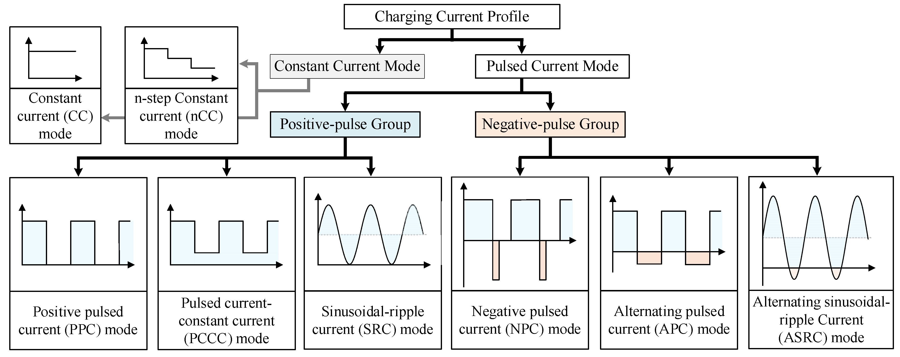
Figure 2 shows the classification of charging current profiles, which can be categorized as CC mode and pulsed current mode. Several pulsed current modes have been proposed to improve battery charging performance and thermal safety [
7,
8]. First, as a positive-pulse group, the positive pulsed current (PPC) mode applies intermittent positive current with rest intervals, which helps reduce polarization and internal heating while maintaining a simple, unidirectional circuit. The pulsed current–constant current (PCCC) mode begins with a pulsed phase to mitigate initial polarization effects and then transitions to a CC stage for efficient energy delivery, providing a balance between safety and charging speed. The sinusoidal ripple current (SRC) mode superimposes a sinusoidal waveform onto the charging current, aiming to enhance ionic mobility, though it requires advanced control and filtering with limited practical benefit.
In constant, as a negative-pulse group, the negative pulsed current (NPC) mode introduces short reverse current pulses to dissolve lithium plating and improve electrode uniformity, though it requires bidirectional current control and leads to greater thermal stress. The alternating pulsed current (APC) mode continuously alternates between positive and negative pulses, offering some electrochemical benefits but causing significant heat generation and reduced charging efficiency. Finally, the alternating sinusoidal ripple current (ASRC) mode applies a fully alternating sinusoidal current, which may relax interfacial stress but results in high thermal load and low efficiency, making it less suitable for practical charging systems.
Among the various pulsed and ripple charging strategies PPC and PCCC modes demonstrated the best combination of thermal safety, charging performance, and practical feasibility. These modes offer similar performance to conventional CC charging while maintaining low thermal stress and requiring only simple unidirectional circuitry.
Table 1 presents a comparative summary of the CC and PPC charging modes under the same average current condition, 1C. While PPC can mitigate polarization and reduce internal heating due to intermittent rest periods, experimental results in [
7,
8] indicate that its actual thermal advantage over CC is marginal. As shown in
Figure 3, the maximum temperature rise observed under PPC mode was slightly higher than that of CC mode at equivalent average current, likely due to peak 2C surges inducing momentary thermal stress. It may induce abrupt temperature spikes that are difficult to regulate in real time. In contrast, CC charging provides a more stable thermal profile, making it potentially more suitable for precise thermal management during the entire charging process.
Furthermore, PPC operation requires more complex current modulation and waveform control, as well as power converter hardware capable of handling 2C instantaneous current, which increases design burden. Although polarization relaxation is more effective under PPC, the CC mode can be easily extended to hybrid or multi-stage schemes to incorporate rest intervals or additional optimization stages if needed. Therefore, from a power electronics and implementation standpoint, the CC charging strategy remains preferable for thermal stability and system efficiency.
In contrast, negative-pulse groups such as NPC, APC, and ASRC require bidirectional current control, which substantially increases circuit complexity. As noted in [
7], such modes are not easily applicable in practical battery charging systems due to the challenges in generating controlled reverse current path within the given converter topology. Although the negative-pulse group can alleviate polarization, suppress lithium plating, and promote uniform electrode reactions, they offer no advantage in charging speed compared to CC mode. Moreover, during the reverse current intervals, energy is intentionally discharged rather than stored, leading to a net loss in charging efficiency.
Based on the selected topology shown in
Figure 1, a reverse current path can be constructed independently of the primary stage by turning off all relevant switching devices, such as S
1 through S
4. If power is unintentionally transferred to the primary side, this discharging power becomes inefficient from the standpoint of power conversion, contributing nothing to the charging process. This reverse current path is not exclusive to the LLC resonant converter but can be applied to any full-bridge-type isolated DC-DC topology.
As illustrated in
Figure 4a, by turning on S
5 and S
8, the battery energy can be directed into the output filter inductor
Lf and the transformer’s leakage inductance. The stored energy in these components can subsequently return to the battery by turning off all secondary-side switches, forming a free-wheeling path through anti-parallel diodes, as shown in
Figure 4b.
This intentional discharging–charging loop enables temperature regulation of the battery without activating the primary-side operation. Such a strategy may be utilized during the discharge intervals of negative-pulse current modes. However, the discharge current is inherently limited by the values of the output filter and transformer inductances. Moreover, the actual charging current cannot be reliably ensured, as it directly depends on the amount of preceding discharge current, which is only present during the discharge phase. Additionally, this approach is effective only under high-state-of-charge (SOC) conditions.
Although sinusoidal ripple current modes such as SRC and ASRC are beneficial to ion diffusion and interfacial kinetics in LIBs, its implementation in EV on-board chargers remains impractical. Conventional DC-DC converter topologies such as dual active bridge (DAB), phase shifted full bridge (PSFB), or LLC are optimized for steady-state DC operation, and synthesizing sinusoidal current waveforms requires complex modulation, fast current control loops, and additional filtering stages. Moreover, tracking a time-varying sinusoidal reference using standard proportional–integral (PI) controllers makes phase lag and harmonic distortion, making accurate current shaping challenging under varying load conditions. In addition, as highlighted in [
18,
19], the SRC mode requires precise generation of high-frequency current profiles and accurate impedance modeling of the battery, which are difficult to realize using the power conversion system.
Based on the comparative analysis presented above, including the key performance criteria summarized in
Table 2, this study focuses on charging strategies that exhibit both thermal safety and high practical feasibility in the context of EV OBCs. Consequently, charging modes such as NPC, APC, SRC, and ASRC are excluded from further consideration due to their poor thermal characteristics, low implementation viability, and control complexity in practical power converter systems.
4. Proposed of the Charging Current Profile for Batteries
Conventional OBCs typically do not consider the thermal characteristics of the battery during charging, which can lead to significant degradation of LIB lifetime, particularly under low-temperature conditions. However, since OBCs are primarily used for slow charging, they offer sufficient time to actively regulate the thermal state of the battery during the charging process. Motivated by this, this paper proposes a novel control strategy that dynamically adjusts the output current ripple of the OBC based on battery temperature, thereby maintaining the battery within an optimal temperature range of 25–35 °C based on [
17,
20,
21].
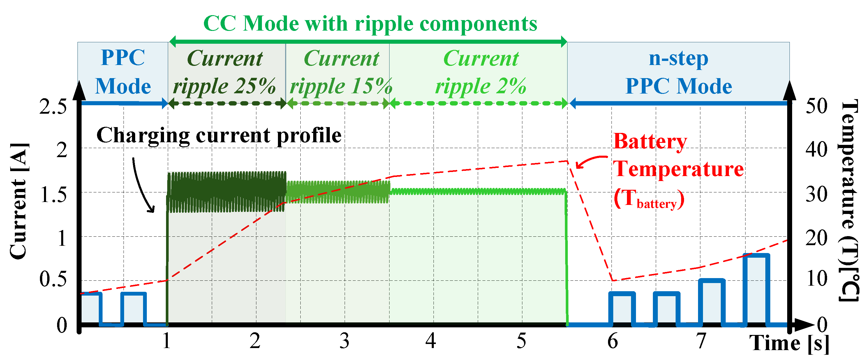
The core of the proposed charging strategy lies in the “CC mode with ripple components”, located at the center of
Figure 5. In this mode, the average charging current is kept constant, while the ripple component of the output current is modulated to actively manage the thermal behavior of the battery. Specifically, a high-frequency ripple is superimposed on the DC current, with the ripple amplitude adaptively adjusted to temperature conditions (e.g., 25%, 15%, or 2%) to induce controlled heating. Experimental results confirm that larger ripple amplitudes produce greater temperature rise in the battery. The degradation effect of high-frequency ripple currents on battery lifetime is significantly less pronounced compared to that of low-frequency ripples [
22].
As analyzed in the preceding sections, both PPC and CC modes have demonstrated superior characteristics in terms of thermal safety and charging efficiency. Accordingly, the proposed hybrid charging profile incorporates these two modes at the front and rear sections of the current waveform, as illustrated in
Figure 5. In particular, the PPC mode includes intermittent rest periods, which are effective in promoting electrochemical diffusion and recovery. An extended form, referred to as the n-step PPC mode, is also considered, in which multiple pulsed segments are sequentially applied. Although similar methods have been described in the literature as “multi-stage charging” [
19], this work adopts the more intuitive term “n-step” for clarity. Furthermore, because these rest periods are also effective at lowering battery temperature, when the temperature exceeds 35 °C, appropriate idle intervals (0 A command) can be inserted into the PPC or n-step PPC sequence to help reduce it.
Therefore, incorporating a high-frequency component into the charging current is a highly effective strategy, as it enables rapid and precise thermal control. The sequence configuration in
Figure 5, which comprises PPC mode, CC mode with ripple components, and n-step PPC mode, can be varied or omitted as needed. It is important to note that temperature control is predominantly carried out at the CC mode with ripple components.
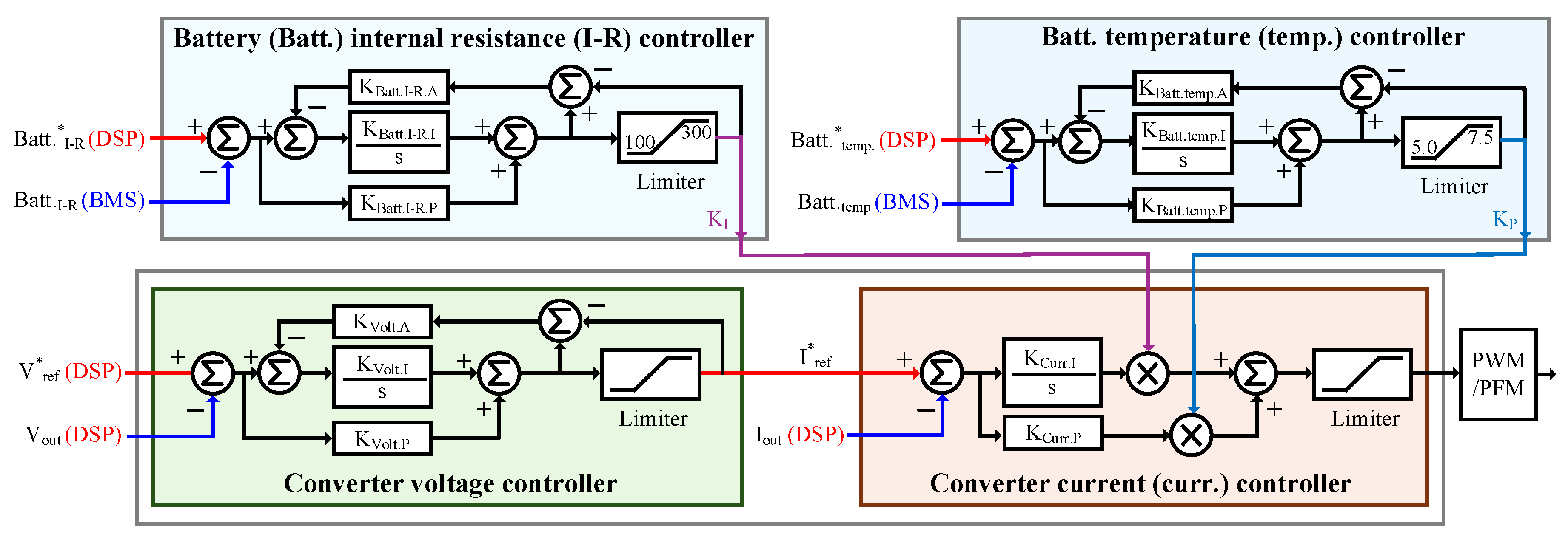
Figure 6 presents the control block diagram for the proposed charging strategy. In the figure,
* indicates a reference signal. It adopts a conventional cascaded structure composed of a voltage controller and a current controller, augmented by a battery temperature controller and a battery internal resistance controller. In detail, frequent charge–discharge cycling of LIBs leads to the accumulation of reaction byproducts, such as the growth of solid electrolyte interphase and other surface films on the electrode, which significantly increases internal resistance [
15,
22]. This elevated internal impedance deteriorates the electrode kinetics and accumulates electrical losses, thereby resulting in progressive heat generation and performance degradation.
To mitigate such effects, the proposed system utilizes a battery temperature controller and a battery internal resistance controller to maintain the battery within an optimal thermal range of 25–35 °C. These auxiliary controllers compute gain multipliers, KP and KI, that are applied to the proportional and integral components of the PI current controller, enabling real-time adjustment of ripple magnitude and control responsiveness based on battery state. These controllers actively regulate the output ripple current and dynamically adjust KP and KI in accordance with the battery’s thermal and resistance states, minimizing internal resistance buildup that otherwise increases in near-proportional relation to the number of cycling events.
The setpoints and measured values for both voltage and current controllers are handled via a digital signal processor (DSP), while the gain multipliers from the temperature and resistance controllers are computed in the DSP using real-time inputs from the battery management system (BMS), which provides temperature and internal resistance information. The battery temperature controller directly modulates the P-gain of the PI controller in response to instantaneous temperature variation, allowing fast dynamic control of ripple amplitude. In contrast, the battery internal resistance controller updates the I-gain based on cumulative resistance changes, contributing to improved steady-state accuracy and long-term control stability.
Figure 7 visualizes the gain multipliers applied to the PI current controller as functions of battery temperature and internal resistance. In the figure, * indicates a reference signal. For instance, when the battery temperature exceeds 25 °C, the ripple component is suppressed to within 2% by setting the ratio
KI/
KP = 20. Conversely, when the temperature falls below 25 °C, the ripple is deliberately increased—up to a maximum
KI/
KP ratio of 40—to elevate the battery temperature toward the optimal range.
5. Experiment Results
Figure 8 summarizes the experimental setup used to validate the proposed charging-current control method. A 11 kW OBC is constructed by connecting two 5.5 kW modules with input and output parallel. Module#1 and Module#2 are indicated in
Figure 8, and each module implements the topology shown in
Figure 1. This study specifically focuses on the battery charging current regulation at the DC-DC stage, which is composed of an LLC resonant converter following a single-phase PFC converter in the OBC system.
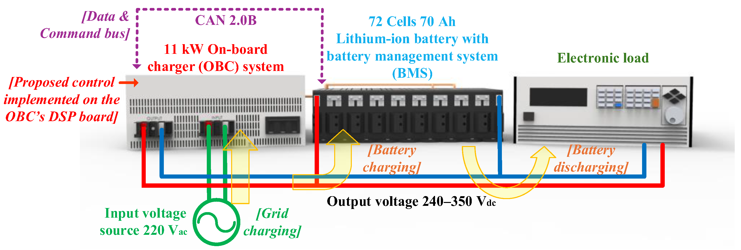
Figure 9 summarizes the system-level functional blocks and the detailed wiring of the test bench. Input of the OBC is supplied from a 220 V
RMS AC grid, which is rectified and regulated to a 415 V DC-link; this regulated DC-link feeds the LLC resonant converter. It delivers a DC output of 240–350 V
DC to interface with the battery. On the load side, a LIB pack with a BMS and a programmable electronic load is used to emulate discharge conditions. The proposed charging strategy is implemented on a DSP board installed inside the OBC, where a TMS320F280335 executes the control algorithm in real time. The battery pack, built from SK On E710 NMC pouch cells, is configured as 72 series-connected cells (≈70 Ah nominal) for EV applications, and the BMS is modularized in 8-cell groups. Since battery temperature is a critical variable for extending battery life, the OBC system communicates with the BMS via CAN 2.0B protocol to receive real-time data including battery voltage, temperature, internal resistance, and charge/discharge current. Key system parameters are summarized in
Table 3.
Figure 10a shows the voltage and current waveforms across the transformer of the LLC resonant converter under steady-state operation. The results confirm that zero-voltage switching (ZVS) is successfully achieved.
Figure 10b presents the voltage across the DC-link capacitor and its corresponding charging/discharging current. The waveform clearly reveals high-frequency charging and discharging behavior due to switching operations. The time scale is sufficiently short such that low-frequency components, such as the second harmonic of the grid frequency, are not visible.
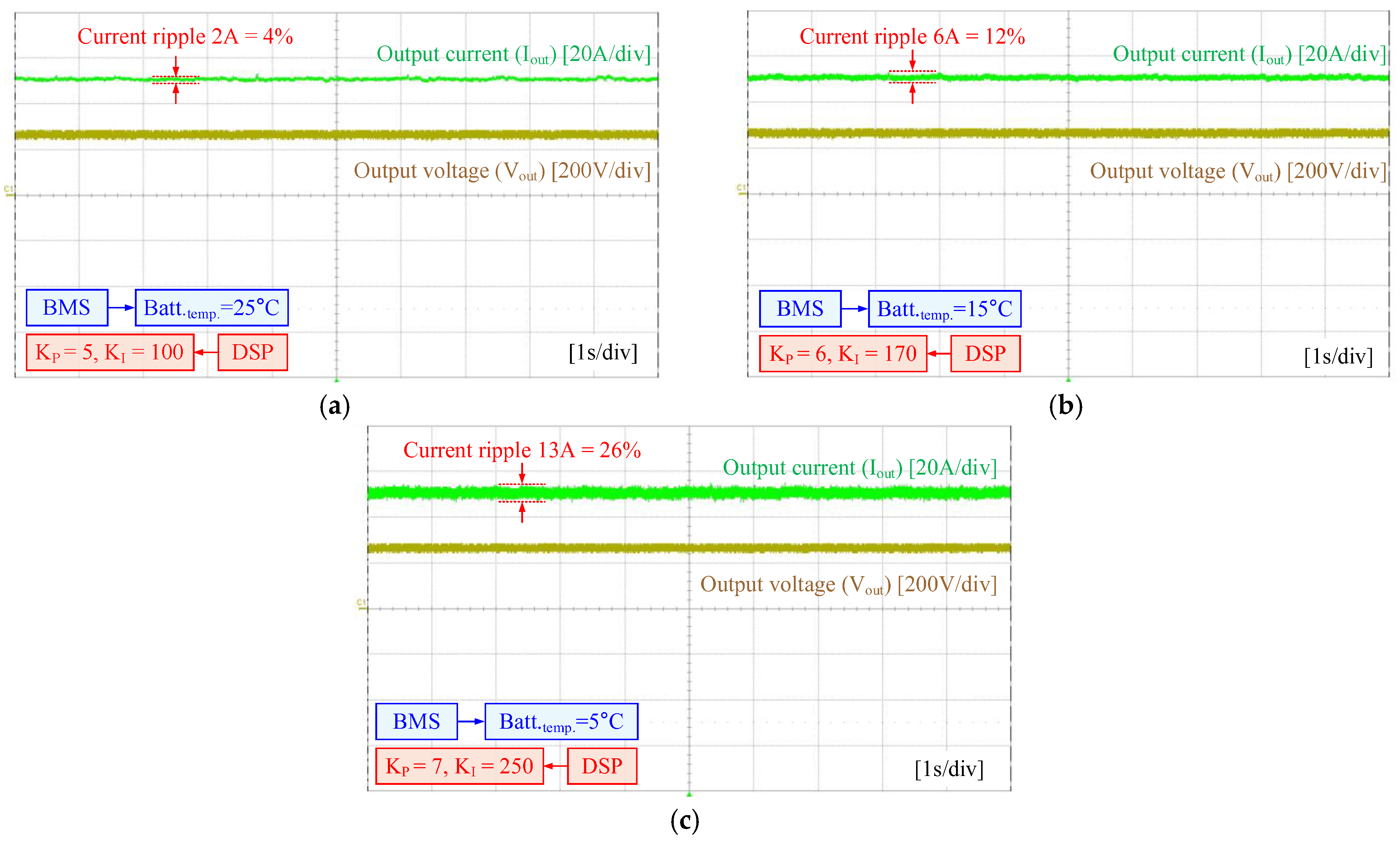
Figure 11 presents experimental results of the proposed CC charging strategy incorporating PI-based ripple control. The voltage and current reference values are set to 240 V and 50 A, respectively. As illustrated in
Figure 6, the output current ripple magnitude adaptively varies according to the gain multipliers (K
P and K
I), which are determined based on battery temperature and internal resistance obtained through two controllers: the battery internal resistance controller and the battery temperature controller.
At a battery temperature of 25 °C, which represents an optimal condition for charging, the controller sets the proportional and integral gains to K
P = 5 and K
I = 100, respectively. As illustrated in
Figure 11a, this yields a gain ratio of 20 and results in a current ripple of approximately 4%. When the battery temperature decreases to 15 °C, the controller responds by increasing the gains to K
P = 6 and K
I = 170. The corresponding ripple, as observed in
Figure 11b, rises to around 12%, helping to elevate the battery temperature toward the target range. In the case of a low battery temperature of 5 °C, the gains are further increased to K
P = 7 and K
I = 250, resulting in a gain ratio exceeding 35.7. As demonstrated in
Figure 11c, this leads to a ripple magnitude of over 25%, which effectively accelerates thermal buildup and improves charging performance under cold-start conditions.
To quantitatively verify the correlation between the proposed CC charging method with superimposed ripple components and the resulting battery temperature response, experimental validation was conducted. As illustrated in
Figure 12, the battery temperature exhibited a gradual increase over time during charging, and it was experimentally confirmed that the rate of temperature rise becomes more substantial as the current ripple magnitude increases. These findings emphasize the critical importance of maintaining an appropriate temperature range during charging to enhance battery longevity and utilization. The proposed ripple-based thermal control strategy demonstrates its effectiveness in achieving this objective.
In particular, the method enables a straightforward and implementable means of regulating ripple magnitude by adjusting the gain multipliers (K
P and K
I) of the PI current controller.
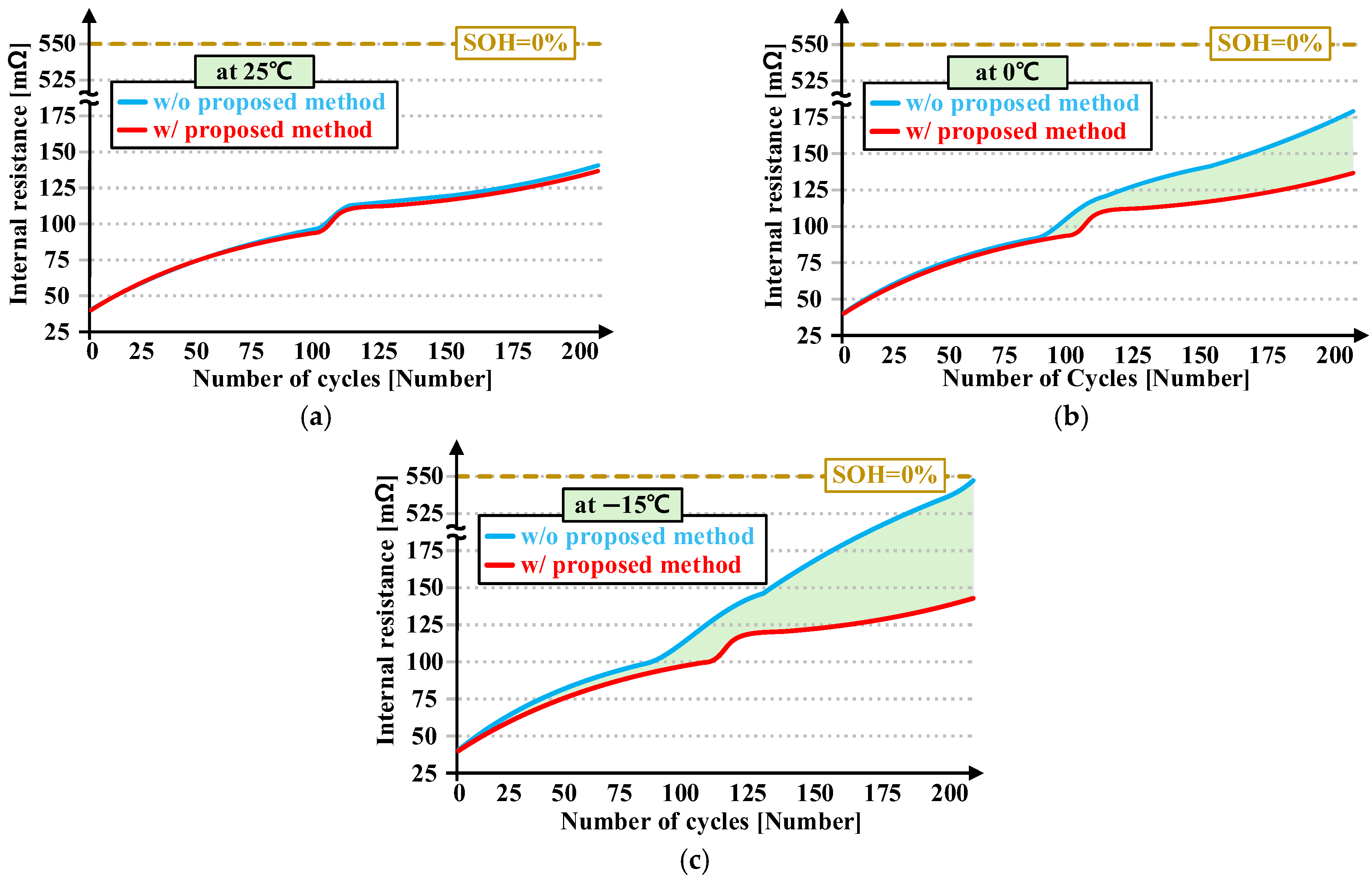
Figure 13 shows the variation in internal resistance of LIBs over 200 charge–discharge cycles conducted at three different temperatures: 25 °C, 0 °C, and −15 °C. Temperature control was provided by a constant-temperature/constant-humidity chamber; prior to cycling, LIBs were equilibrated at each target temperature for 48 h. The results compare a CC charging method with the proposed ripple-based control strategy, enabling a performance-based evaluation of battery lifetime extension. In this analysis, end-of-life (EOL) is defined as the point at which the internal resistance of a single battery cell reaches 550 mΩ, corresponding to a state of health (SOH) of 0%.
Figure 13a shows the result under 25 °C. Since this temperature lies within the optimal operating range, only a marginal difference is observed between the CC charging method (regarded as a without proposed method) and the proposed method in terms of internal resistance increase, indicating negligible lifetime improvement in this condition.
In contrast,
Figure 13b presents the results at 0 °C. For the CC charging method, a sharp increase in internal resistance is observed after approximately 80 cycles. However, with the proposed method, the increase in internal resistance is significantly mitigated. As a result, the number of cycles required to reach the SOH threshold is extended, yielding an estimated lifetime improvement of approximately 23%.
Figure 13c illustrates the scenario at −15 °C. In the absence of the proposed control, the internal resistance again rises steeply beyond 80 cycles, reaching nearly 550 mΩ at 200 cycles, indicating that EOL is effectively reached. Conversely, the application of the proposed method results in a slower rate of resistance increase, extending the projected EOL, which corresponds to a lifetime improvement of roughly 37%.
These results confirm that LIBs are highly vulnerable to accelerated degradation under low-temperature conditions due to internal resistance buildup. Furthermore, the proposed ripple-based control effectively suppresses this resistance growth, thereby enhancing the operational lifetime of the battery under such harsh environmental conditions.

