Article

A Novel Compact Beamforming Network Based on Quasi-Twisted Branch Line Coupler for 5G Applications

Communications Research Group, Department of Electronic and Electrical Engineering, University of Sheffield, Sheffield S1 3JD, UK
*
Author to whom correspondence should be addressed.
Electronics 2025, 14(17), 3565; https://doi.org/10.3390/electronics14173565
Submission received: 3 August 2025 / Revised: 3 September 2025 / Accepted: 4 September 2025 / Published: 8 September 2025

Abstract

This paper presents a novel compact 4 × 4 Butler matrix (BM) employing a quasi-twisted branch line coupler (QBLC) as the unit cell to achieve enhanced bandwidth performance. The proposed BM integrates four QBLCs, a uniquely designed 0 dB crossover, and a 45° phase shifter, all fabricated on a double-layer Rogers RO4003C substrate with a thickness of 0.8 mm, dielectric constant (εr) of 3.3, and a loss tangent of 0.0027. A common ground plane is used to separate the layers. Both simulation and experimental results indicate a reflection coefficient of approximately −6.5 dB at the resonant frequency of 6.5 GHz and isolation levels better than −20 dB at all ports. The system achieves output phase differences of ±13°, ±41°, ±61°, ±89°, and ±120° (±10°) at the designated frequencies. The BM occupies a compact area of 13.8 mm × 38.8 mm, achieving a 92.5% size reduction compared to conventional T-shaped BM structures. The design was modeled and simulated using CST Microwave Studio, with a strong correlation observed between simulated and measured results, validating the design’s reliability and effectiveness. Furthermore, the BM’s beamforming performance is evaluated by integrating it with a 1 × 4 microstrip antenna array. The measured return loss at all ports is below −10 dB at 6.5 GHz, and the system successfully achieves switched beam steering toward four distinct angles: −5°, +6°, +26°, −24°, +43, and −43 with antenna gains ranging from 7 to 10 dBi.

1. Introduction

5G meets rising demands for higher data rates and user capacity by tackling channel limitations, multi-path fading, and co-channel interference [1]. Increasing users worsen interference, degrading QoS and driving research into beamforming networks [2]. Thus, 5G millimeter-wave applications require high-gain directional antennas with beamforming to overcome path loss, fading, and interference while improving signal-to-noise ratio [3].
Beamforming can use phased arrays (analog/digital) for continuous steering but requires complex, costly circuitry. In contrast, switched beamforming offers discrete steering with simpler, cheaper hardware, making it preferable when precise continuous control is not needed [4].
In switched beamforming, passive circuits are preferred for simplicity, low power, and cost efficiency, with Butler, Blass, and Nolen matrices as common options [5]. The Butler matrix, needing the fewest passive components, is the optimal choice for passive switched-beam antennas [6].
The Butler matrix (BM) is widely used in 5G for its simplicity, cost-effectiveness, easy [2] fabrication, and bias-free reciprocal operation. A conventional BM includes 3 dB BLCs, crossovers, and phase shifters, with BLC size determined by operating frequency. At low frequencies, BLCs and crossovers enlarge the network, increasing losses and device size, driving research into miniaturizing the BM for compact wireless systems [7].
In [4], compactness was achieved using a dual-layer substrate: low dielectric constant (εr) for the antenna and high dielectric constant (εr) for the feed. While size was reduced without degrading performance, the design showed unstable input impedance across ports.
A metamaterial transmission line structure based on an interdigital capacitor unit cell was employed to achieve Butler matrix miniaturization [2]. However, as the proposed design is based on the conventional crossover made of cascaded branch lines, it still shows rather large overall dimensions of 70 × 75 mm2. Open stubs were added to the transmission lines constructing the BLC to miniaturize it, as employed by [8]. Furthermore, the crossover has been eliminated from the Butler matrix circuit to miniaturize it to the limit. However, the overall physical size remained significant to some extent, with dimensions of 115 × 65 mm2. Additionally, it showed a somewhat small bandwidth of 200 MHz.
A conventional meandering line technique was employed to reduce the size of the coupler and, consequently, the Butler matrix covering the frequency band of 5.8 GHz [9]. This method achieved a 56% miniaturization of the BLC size and a 36% reduction in the overall feeding network size compared to the conventional matrix. An Electromagnetic Metamaterial Transmission Line (EM-MTM TL) based on symmetric double spiral lines (SDSLs) was chosen in [10] to miniaturize the Butler matrix. The proposed technique reduced the size of a 3 dB branch-line coupler and a 0 dB crossover operating at 0.86 GHz by 84.8% and 85.7%, respectively. The combined Butler matrix, based on the BLC and 0 dB crossover, achieved an 80.9% size reduction compared with the conventional Butler matrix. Another attempt to miniaturize the BM involved avoiding the crossover [11]. A back-to-back placed bilayer microstrip structure was used, where the BM circuit’s components are placed over two layers. Moreover, a three-branch line directional coupler was employed to expand the operational bandwidth of the Butler matrix.
In [12], a compact 28 GHz mmWave antenna for 5G and future wireless systems is presented. Using two open stubs and a 30° bent strip, the antenna achieves a 2.9 GHz bandwidth and up to 97% efficiency. Extending it to a four-element array increases the gain to 10.1 dBi while maintaining compactness and simple fabrication. The design demonstrates efficient radiation, stable bandwidth, and focused patterns.
Recently, [13] introduced the idea of meandered lines and an interdigital capacitor (IDC) unit-cell-based composite right/left-handed transmission-line (CRLH-TL) metamaterial (MTM) structure to compact the BM. They managed to reduce the BM’s overall dimensions to 78% compared to traditional T-shaped BM designs. Previous works have employed miniaturization either through meandering structures, which remain relatively large, or metamaterial transmission lines (MTM-TLs), which, despite achieving size reduction, are complex and suffer higher transmission losses due to slotting and interdigital capacitors (IDCs) that introduce significant coupling losses.
In this study, a compact branch-line coupler (BLC)-based Butler matrix (BM) beamforming network is proposed. The design builds upon the BLC introduced in the authors’ previous work [7], which employed a longitudinal bisection of a conventional BLC into two segments twisted around one another. The BLC was implemented using a microstrip double-layer transmission line (MDL-TL) structure. The miniaturization technique combined meandering with a slow-wave structure. This approach achieved a 49.9% size reduction compared to a conventional BLC while improving the relative bandwidth to 75.8%.
Based on this structure, the proposed BM was constructed using four interconnected BLCs on the same substrate. This configuration offers an additional advantage by eliminating the conventional crossover, which typically introduces drawbacks such as increased size and transmission losses. Consequently, the proposed design attains a relatively high miniaturization ratio.
The BM is implemented on a double-layer 0.8 mm Rogers 4003C substrate (εr = 3.5, tan δ = 0.027). Simulation and measurement results show a 92.5% size reduction and 15.3% bandwidth at 6.5 GHz, highlighting its potential for compact sub-6 GHz 5G beamforming networks. The paper is organized as follows: Section 2 outlines the Butler matrix structure; Section 3 presents the proposed BM based on the quasi-twisted BLC; Section 4 discusses the antenna configuration and results; and Section 5 concludes.

2. Butler Matrix Structure

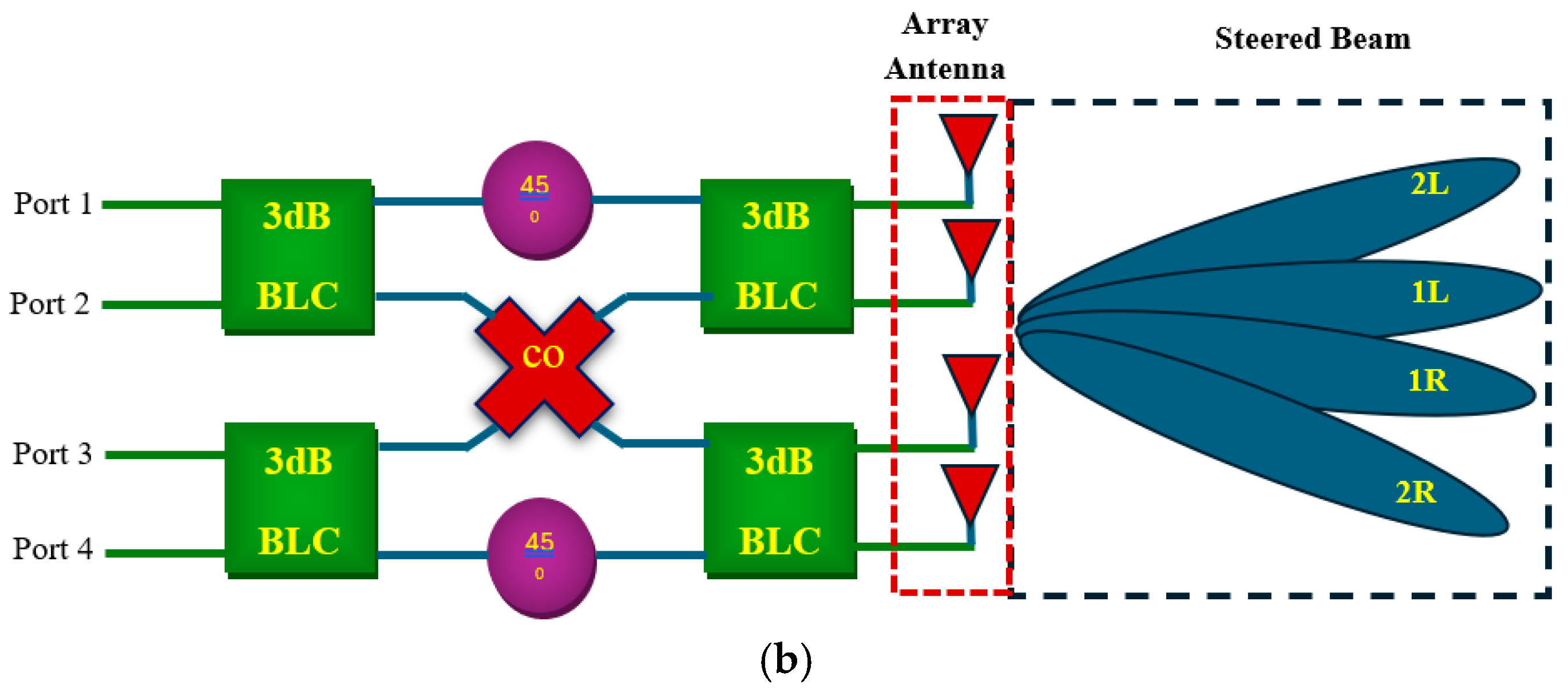
The block diagram of a conventional BM is illustrated in Figure 1a. The 4 × 4 Butler matrix consists of four input ports and an equal number of output ports. Its structure comprises four 3 dB BLCs, two 45° phase shifters, and 0 dB crossovers [14]. Since the input-to-output signal transmission in the Butler matrix passes through two 3 dB hybrid couplers (or branch line couplers), the theoretical transmission coefficient of an ideal Butler matrix is 6 dB, excluding any additional losses. Consequently, the power level at the four output ports (P5–P8) is expected to be 6 dB lower than the input power at P1–P4.
Furthermore, the phase distribution at the output ports is determined by the specific input port (port 1, 2, 3, or 4) through which the signal is applied. The signal phases at the output ports (ports 5, 6, 7, and 8) exhibit fixed phase differences denoted as θ 1 o , θ 2 o ,   θ 3 o , and θ 4 o , based on the input port selection as shown in Table 1 [2]. When an array of antenna elements is connected to these output ports, as depicted in Figure 1b, the resulting radiation beam is directed towards four distinct angles (or beams). These beams are conventionally designated as 1L, 2R, 2L, and 1R, corresponding to the excitation of input ports 1, 2, 3, and 4, respectively.

3. Proposed BM Feed Network Based on Quasi-Twisted BLC

The fundamental building block of the BM is the BLC. A branch line coupler is a four-port symmetrical microwave network characterized by its ability to equally split the input power between two output ports with a 90° phase difference. Additionally, the port adjacent to the input remains fully isolated from the signal transmission [15]. In this work, the BM was developed based on a compact broadband quasi-twisted branch line coupler [7], as illustrated in Figure 2. The design is implemented on a double-layer substrate configuration, isolated by a common ground plane. Each of the input and output ports, along with the pair of horizontal arms of the BLC—each having a length of λg/4—is uniquely constructed around the double-layer substrates. For the vertical arms, a technique known as the Periodically Loaded Slow-Wave Structure was employed. The different parts of the BLC are interconnected through vias penetrating the common ground plane. This approach enabled a significant area reduction of approximately 50% compared to the conventional BLC design at the same operating frequency.
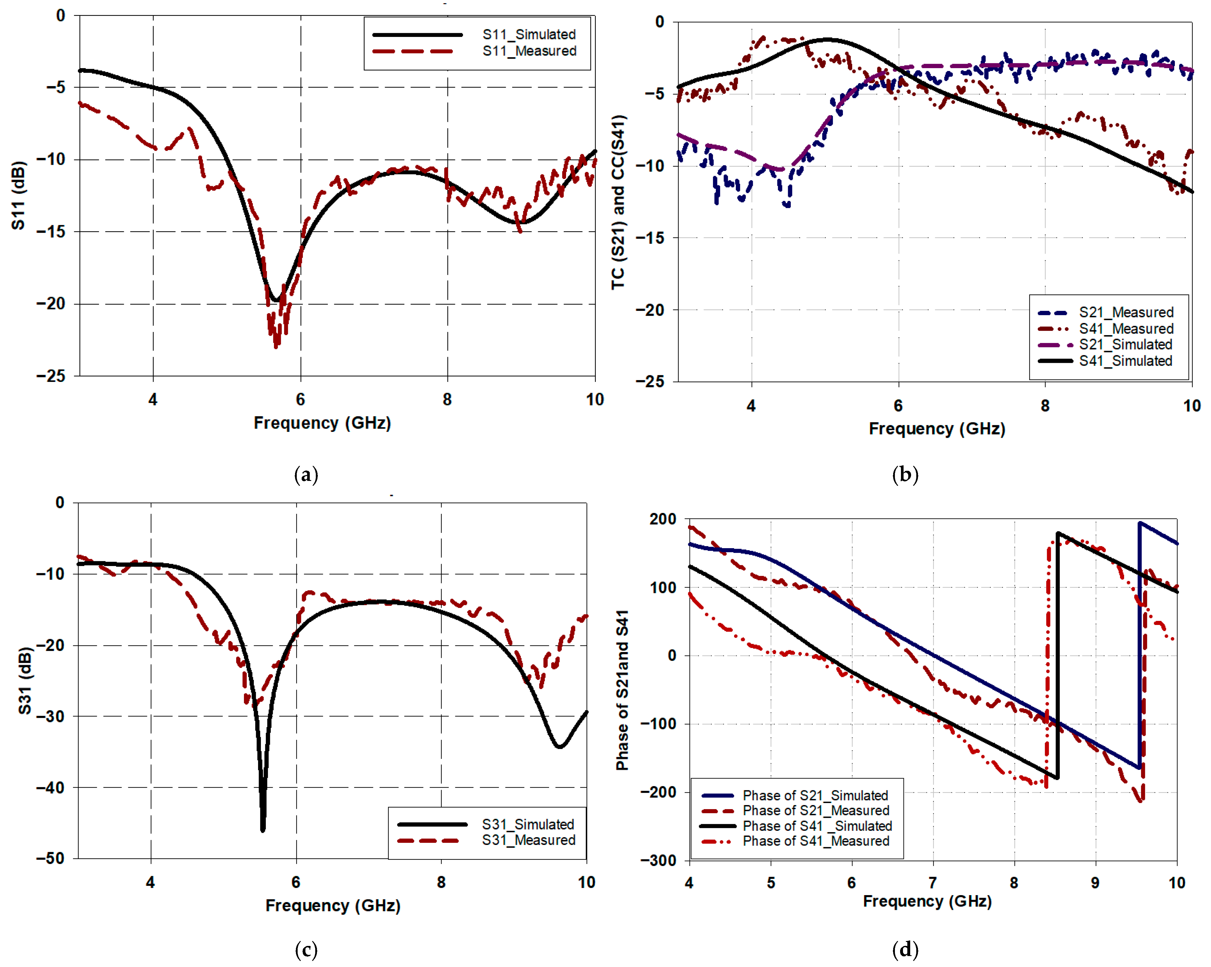
The scattering parameter results of the referenced branch line coupler (BLC), as illustrated in Figure 3, demonstrate equal power division between the output ports (S21 and S41), both approximately −3 dB at 6.5 GHz. However, the delivered power at port 4 gradually decreases, while the power at port 2 remains nearly constant or even slightly increases. In other words, there is a power imbalance between the output ports. This discrepancy is likely caused by substrate and via losses, as the input and coupled ports are located on opposite sides of different substrates. Nevertheless, when constructing the BM from the reference BLC, this issue can be partially mitigated by connecting successive BLCs in an alternating (inverted) configuration. The reference coupler also exhibits an isolation level (S31) of approximately −15 dB. Furthermore, the phase difference between the output signals (∠S21 and ∠S41) is approximately 90 degrees.
Based on the reference BLC, the BM is constructed from four BLCs and a unique crossover incorporating two 45° phase shifters, as illustrated in Figure 4. It can be observed that the last two couplers (BLC#3 and BLC#4) are connected in an inverted configuration compared to the first two (BLC#1 and BLC#2). This design choice addresses a slight imbalance in power distribution within the unit cell, where the coupling coefficient deteriorates beyond 6 GHz. However, the transmission coefficient remains stable, maintaining a value greater than −3 dB even at 7 GHz [7]. To overcome this issue and ensure stable output power from the BM, the successive BLCs were interconnected in an alternating (inverted) manner.
The proposed design exhibits a distinctive approach for current routing between successive BLCs. In conventional BM architectures, as shown in Figure 1, a 0 dB crossover is typically used for this purpose. The conventional crossover, which consists of a pair of sequentially connected BLCs, presents several challenges for feed networks such as the BM. One of the main issues is the considerable increase in physical size, as its dimensions are inherently dependent on the operating frequency. Consequently, at lower frequencies, the crossover occupies a relatively large area. Additionally, it significantly contributes to increased insertion loss due to the longer signal path required to traverse the crossover, which in turn reduces the power delivered to the output ports.
In the proposed design, the key improvement in terms of size miniaturization was achieved by eliminating the conventional crossover and instead utilizing the spatial distribution of the BM components across double-layered substrates interconnected by vias. A section of microstrip transmission line on the top layer is used to route the signal from port 4 (coupling port) of BLC 1 to input port 1 of BLC 4. Similarly, the bottom layer is used to transmit the signal from port 2 (transmission port) of BLC 2 to input port 3 of BLC 3. This configuration occupies an area of no more than 16.8 mm2, as depicted in Figure 3, compared to 293 mm2 by the traditional crossover, thus significantly reducing the associated insertion loss.
A pair of 45° phase delay lines is implemented between consecutive Butler matrix components, specifically between BLC1 and BLC3 and BLC2 and BLC4, as illustrated in Figure 4. It is worth noting that the proposed BM has a very compact footprint, which prevents direct connection of SMA connectors to the input and output ports, as the size of the SMA connectors exceeds the spacing between these ports. To address this, extensions (EXT.1 and EXT.2) were added to the input and output ports to enable the connection of SMA connectors, as also shown in Figure 4. Naturally, these extensions introduce phase deviations at the output ports, causing the phase differences to differ from those in a conventional Butler matrix. Another contributing factor to the phase shift deviation in the proposed design is the current path, which flows through vias penetrating the double-layer substrate. This also introduces an additional phase delay. Nonetheless, such deviations in phase difference are not considered critical, as they can be easily compensated for by minor tuning of the conventional transmission lines at the output ports.
To determine the additional physical length tuning required to match the output phases of the conventional BM, it is first necessary to calculate the absolute phase difference, as follows:
θ m n = θ m n _ C o n B M θ m n _ P r o p B M
where m and n are equal to 1, 2, 3, or 4, representing the input and output port indices.
The phase difference matrix between the conventional and proposed BMs is shown in Table 2. Therefore, based on the substrate’s parameters at 6.5 GHz, the guided wavelength ( λ g ) will be about 30 mm, and then the physical extension length is given as follows:
L m n = θ m n 360 ° λ g
Accordingly, the additional physical lengths required for the transmission line extensions between the input and output ports—denoted as ∆L5ₙ, ∆L6ₙ, ∆L7ₙ, and ∆L8ₙ, where the first subscript indicates the output port and n represents the input port index—are presented in Table 3 to achieve phase differences similar to those of the conventional BM. As observed in Table 1, the additional path lengths required are not the same at all ports, which is expected due to the presence of two types of additional extensions (EXT.1 and EXT.2), as previously mentioned, as well as the varying number of vias traversed by different paths.
It is worth noting that phase differences can be tuned to achieve any desired phase alignment. However, in this specific design, the selected path lengths were deliberately chosen to provide sufficient space for the SMA connector while maintaining a compact layout—accommodating the SMA connector using the minimal area possible. It is worth noting that when the proposed design is implemented in transmitters, i.e., in end-user devices, these extensions are not required, as the design is integrated directly into the transmitter hardware. The extensions used in this design are solely for the purpose of conducting experimental tests on the fabricated prototype.

Fabrication and Performance Evaluation of the Butler Matrix

The miniaturized BM, illustrated in Figure 4, was fabricated and experimentally validated. The entire circuit was implemented on a Rogers RC4000C dielectric substrate, which possesses a relative permittivity of 3.55, a loss tangent of 0.0027, and a thickness of 0.8 mm, as shown in Figure 5. The overall dimensions of the fabricated structure are 58 × 30 × 1.6 mm3. As previously discussed, a common ground plane is shared between the two substrate layers, resulting in a sandwich-like configuration. To facilitate the connection of SMA connectors, both substrate layers were truncated at their corners, each with a cross-sectional area of 2 × 5 mm2, thereby exposing the ground plane, as depicted in Figure 5b.
The fabricated compact BM was characterized using an HP HEWLETT PACKARD 8720B Vector Network Analyzer (VNA), as shown in Figure 6a. The key scattering parameters measured include the reflection coefficients at the input ports (S11, and S22), the isolation coefficients between input ports (S2x, S3x, S4x), and the transmission coefficients representing signal levels at the output ports (S5x, S6x, S7x, S8x), as well as the phase shift of the output signals (∠S5x, ∠S6x,∠S7x, and ∠S8x) where x represents the number of input ports. These measurements were conducted by connecting the relevant ports to the VNA, while all unused ports were terminated with a 50 Ω load to minimize impedance mismatches and enhance the accuracy and reliability of the measurement results, as illustrated in Figure 6b.
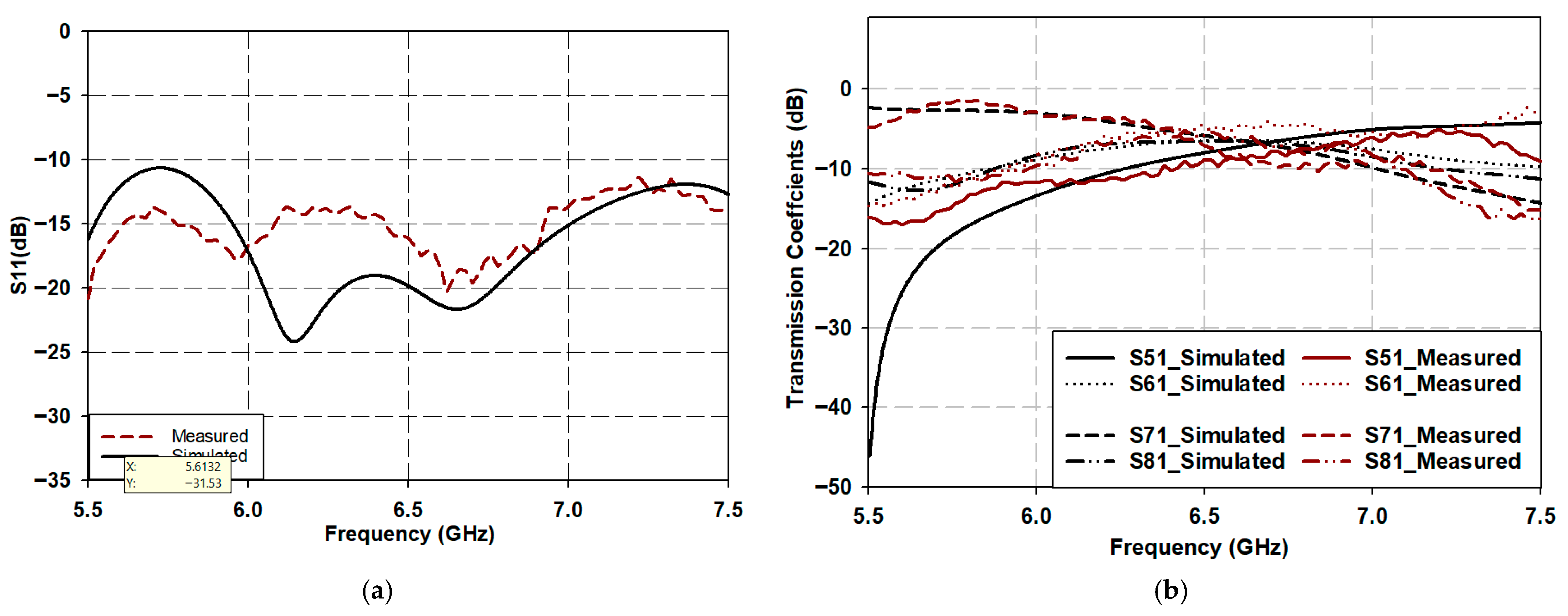
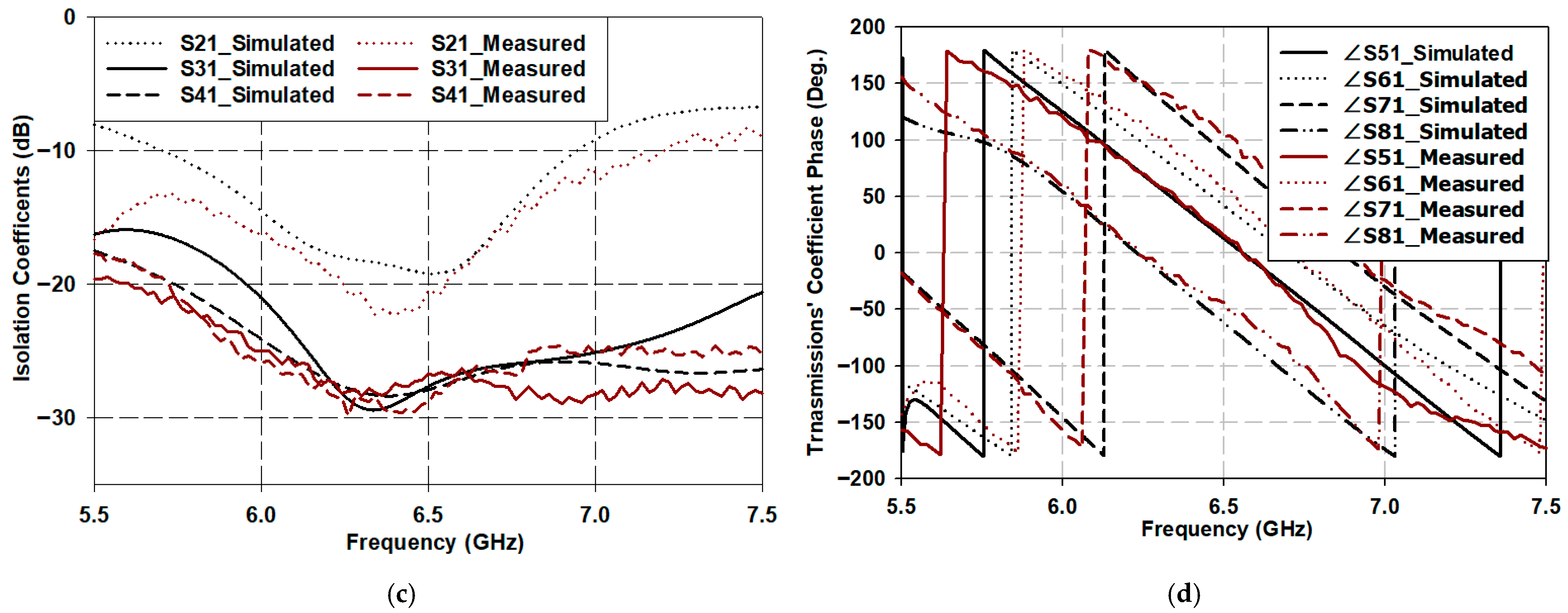
Figure 7 presents a comparison between the simulated and measured scattering parameters when the Butler matrix is excited from ports 1 and 2, respectively. The results for ports 3 and 4 are identical to those of ports 1 and 2, respectively, due to the symmetry between ports 1 and 3, as well as between ports 2 and 4. Therefore, to avoid redundancy and unnecessary complexity in presenting numerous similar results, only the distinct cases associated with different ports are shown.
Figure 7a illustrates the return loss of the BM when excited from port 1, while the remaining ports are terminated with 50-ohm loads. As shown, the BM demonstrates impedance matching over the frequency range of 5.5 to 7.5 GHz, and potentially beyond. However, this entire bandwidth cannot be fully utilized, as other performance parameters become constrained outside the 6 to 7 GHz range. For instance, the insertion loss increases beyond this range. Notably, the BM exhibits excellent impedance matching at approximately the resonant frequency of 6.5 GHz, where the return loss reaches approximately −20 dB or even lower.
Figure 7b illustrates the transmission coefficients S51, S61, S71, and S81 of the proposed BM, which represent the delivered power at the output ports. In an ideal case, the typical transmission coefficients are −6 dB, as the input power is equally split among the output ports.
In this design, the transmission coefficients are observed to be approximately −6.5 dB at 6.5 GHz, which is very close to the ideal value. Additionally, S61 and S81 remain balanced across the entire frequency band of interest, ranging between −6.5 dB and −7 dB, which is also consistent with the expected performance.
However, for S51 and S71, a degree of imbalance in the delivered power is observed at the edges of the operating band. Specifically, at the lower edge, S71 rises to approximately −3 dB, while S51 drops to approximately −11 dB. These values converge near the resonant frequency to approximately −6.5 dB and then reverse beyond it. This indicates that the power delivered to these two ports is unequally distributed, which may be attributed to the lack of extension length, the inherent imbalance of the employed BLC—as discussed in [7]—and the dispersive behavior of the substrate and transmission lines.
Nonetheless, this imbalance does not significantly affect the gain of the antenna array connected to the BM, as the average delivered power to the antenna array remains consistent across the entire operating frequency band of interest.
Referring back to Figure 7c, which illustrates the isolation coefficients S21, S31, and S41 between the input ports, it can be observed that the proposed BM exhibits excellent isolation performance. Specifically, the isolation between port 1 and port 2 exceeds 15 dB within the operating frequency range, while the isolation between port 1 and ports 3 and 4 exceeds 25 dB. Finally, Figure 7d presents the phase angles of the transmission coefficients at the output ports ∠S51, ∠S61, ∠S71, and ∠S81. As shown, the phase angle at port 5 (∠S51) is 13°, while for ports 6, 7, and 8 (∠S61, ∠S71, and ∠S81), the phase angles are 42°, 89.2°, and −62°, respectively, at 6.5 GHz. Notably, the proposed BM demonstrates excellent phase balance throughout the operating frequency range. The phase difference between ports 7 and 6 (i.e., ∠S71–∠S61) remains approximately 47°, while the difference between ports 6 and 5 (∠S61–∠S51) stays at approximately 30°, and between ports 5 and 8 (∠S51–∠S81) remains at approximately 75° across the frequency band. Finally, the phase difference between ports 7 and 8 (∠S71–∠S81) stays at approximately 150°.
Figure 8 illustrates the scattering parameters of the proposed BM when the excitation is applied at port 2. As shown in the figure, the BM exhibits excellent impedance matching at 6.5 GHz, with an operational bandwidth extending from 6 GHz to 7 GHz, as depicted in Figure 8a. Within this frequency band, the remaining parameters, including the signals at the output ports, maintain values close to their expected levels.
Figure 8b presents the transmission coefficients (S52, S62, S72, and S82) of the BM when port 2 is used as the input. It can be observed that, at the frequency of 6.5 GHz, the power is evenly distributed, with values of approximately −6.3 dB, which is very close to the typical value of −6 dB. Furthermore, the output signals at ports 5 and 7 (S52, S72) remain balanced at approximately −6.5 dB across the operational bandwidth, while the outputs at ports 6 and 8 (S62, S82) exhibit a degree of imbalance at the edges of the bandwidth, with S62 exceeding the ideal value (approximately −4 dB), while S82 falls below it (approximately −11 dB). However, as previously mentioned, the average power across all output ports remains close to the ideal value, and thus, this imbalance has a negligible effect on the performance of the connected antenna array in terms of gain. On the other hand, Figure 8c illustrates the isolation between input ports when port 2 is excited. It can be observed that the BM provides excellent isolation among the input ports within the operating bandwidth, with the isolation between ports 2 and 1 (S12) exceeding 15 dB, and the isolation between port 2 and ports 3 and 4 (S32 and S42) exceeding 25 dB.
Finally, Figure 8d shows the phase angles of the power delivered to the output ports. The phase angle of the signal reaching port 5 (∠S52) is 42°, while the phase angles at ports 6, 7, and 8 are 72.3°, −61.2°, and 146.5°, respectively. Consequently, the phase difference between output ports 8 and 6 (∠S82–∠S62) is approximately 75°, between ports 6 and 5 (∠S62–∠S52) is about 30°, between ports 5 and 7 (∠S52–∠S72) is 103°, and finally, between ports 8 and 7 (∠S82–∠S72) is about 207°. Table 4 presents the detailed S-parameters for all input and output port configurations at 6.5 GHz.
Table 5 presents a comparison between the current work and previous studies. It can be observed that the proposed BM feeding network demonstrates an unprecedentedly compact size compared to conventional BM networks. Such a degree of miniaturization has not been achieved previously, as the physical dimensions do not exceed 13.8 × 38.8 mm2. Furthermore, the table indicates that other key parameters are comparable to, or in some cases even superior to, those reported in earlier designs—for instance, isolation, insertion loss, and fractional bandwidth. This provides the proposed design with a clear advantage over prior work, particularly in the context of miniaturizing BM feeding networks.

4. Compact Phased Array Antenna Configuration and Results Discussion

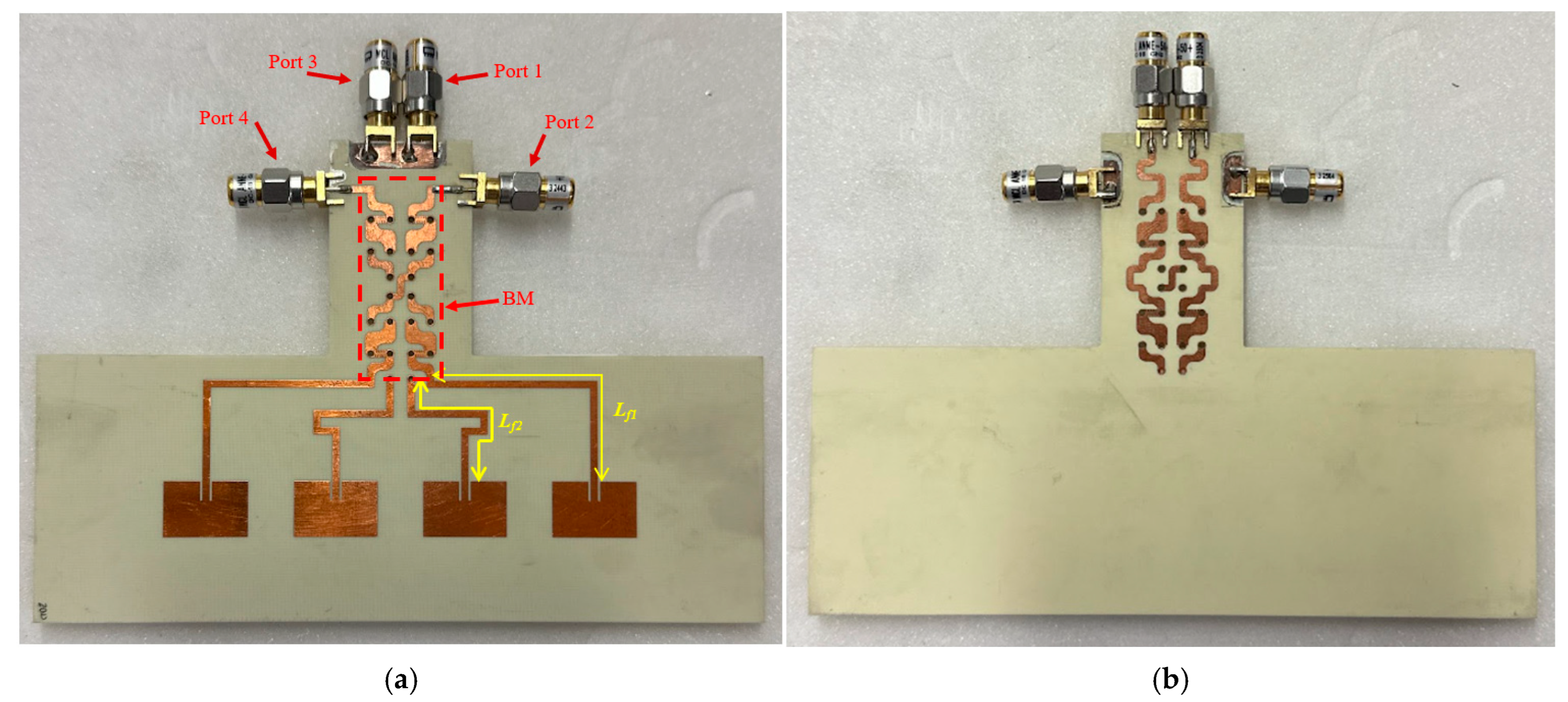
To investigate the feasibility of employing the proposed compact BM in phased array antenna systems and to evaluate its capability for radiation beam steering when excited through different input ports, four conventional rectangular microstrip antennas were connected to the proposed compact BM. The BM substrate configuration is utilized as the foundation for constructing the antenna array. The antenna was initially designed with dimensions of 11.45 × 17.29 mm2 to operate independently at a resonant frequency of 6.5 GHz. It was subsequently connected to the proposed compact BM unit. Due to the highly compact nature of the proposed design, direct connection of the antennas to the BM was not feasible without the use of extension lines. Therefore, two extensions—Lf1 and Lf2—were employed between the BM and the antennas. The antennas were connected at the output ports of BM (port 5 to port 8) and spaced at intervals of λ/2. The antenna array has been fabricated to validate this, as shown in Figure 9.
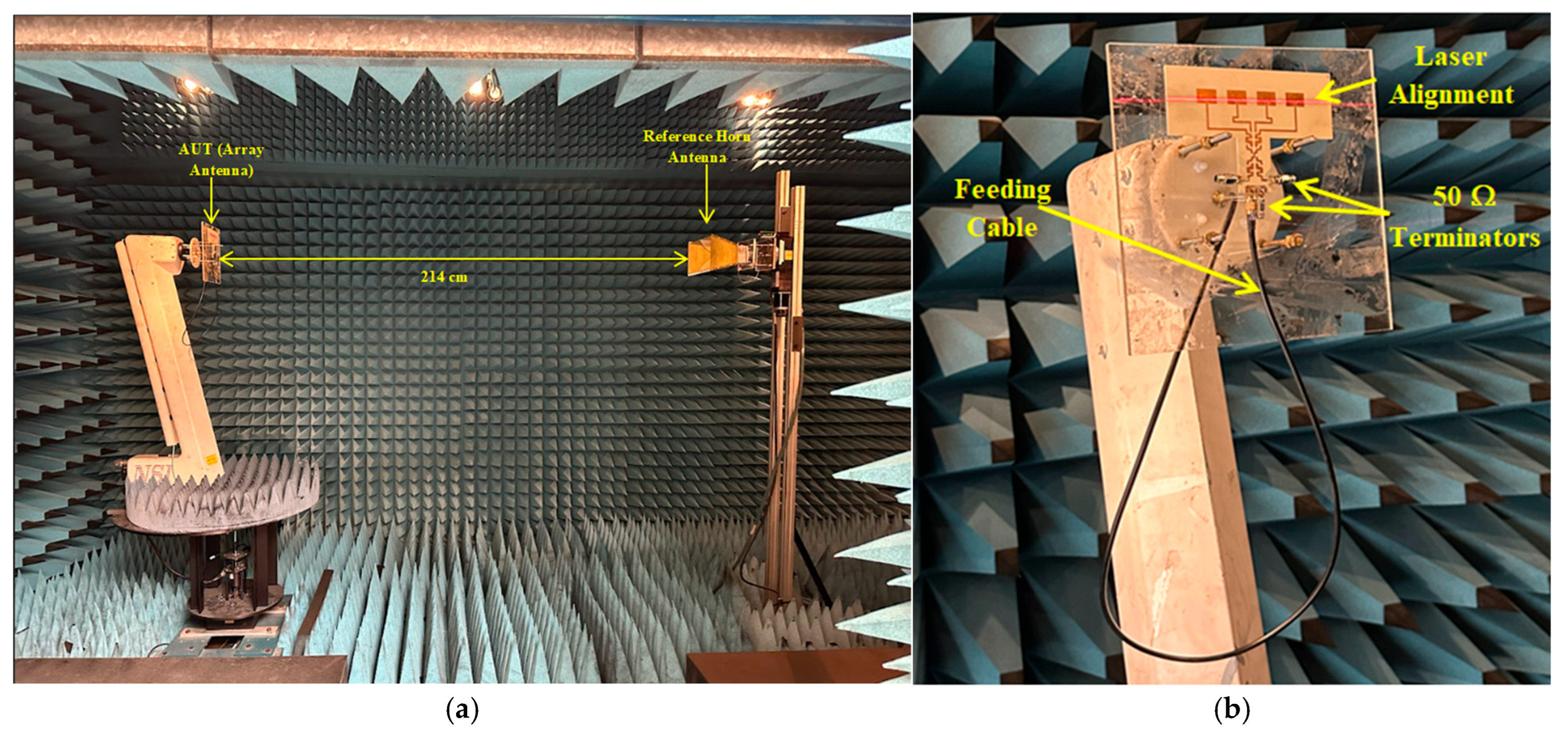
Measurements of the radiation patterns were carried out using the anechoic chamber system, as shown in Figure 10. During the antenna parameter measurements, the port under test was connected to the VNA, while the remaining input ports were terminated with 50-ohm loads, as illustrated in Figure 10b. This setup prevents reflections from unused ports and increases measurement accuracy.
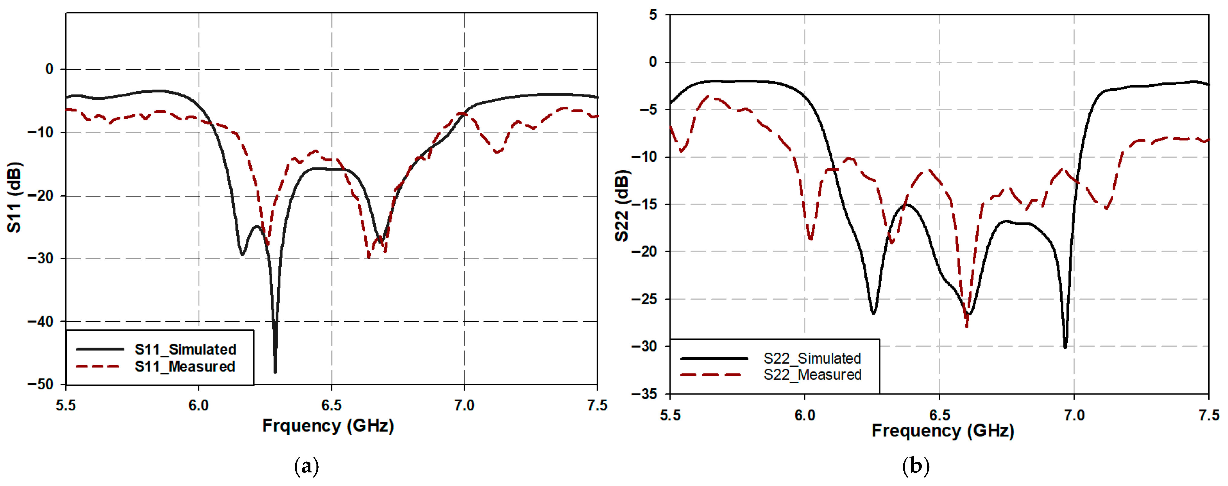
As illustrated in Figure 11a, the S11 remains below the −10 dB threshold over the frequency range of 6.05 GHz to 6.95 GHz, corresponding to a fractional bandwidth of ~13.6%. Similarly, port 2 exhibits a reflection coefficient spanning 6 GHz to 7 GHz, yielding a 15% fractional bandwidth. Due to the symmetrical design of the array, ports 3 and 4 exhibit reflection coefficient characteristics identical to those of ports 1 and 2, respectively.
The phase differences at the output ports of the proposed BM generate different beam angles, commonly referred to as 1L, 2L, 1R, and 2R when the array antenna is connected to these ports. The radiation characteristics of the array antenna are theoretically determined by the normalized array factor (AF), as given in [17].
A F = s i n N π d λ s i n θ s i n θ 0 N π d λ s i n θ s i n θ 0
Here, N denotes the total number of antenna elements, d represents the spacing between adjacent elements in the array, θ0 is the steering (or beam) angle, and λ corresponds to the wavelength of propagation in free space. The beam angle θ0 can be determined using the following expression:
θ 0 = s i n 1 β λ 2 π d
Here, β denotes the progressive phase difference in the excitation current between adjacent antenna elements, as determined by the beam steering network. The inter-element spacing d is typically chosen to be λ/2. Deviations from this value, by selecting d slightly greater or less than λ/2, tend to increase the side lobes in the radiation pattern.
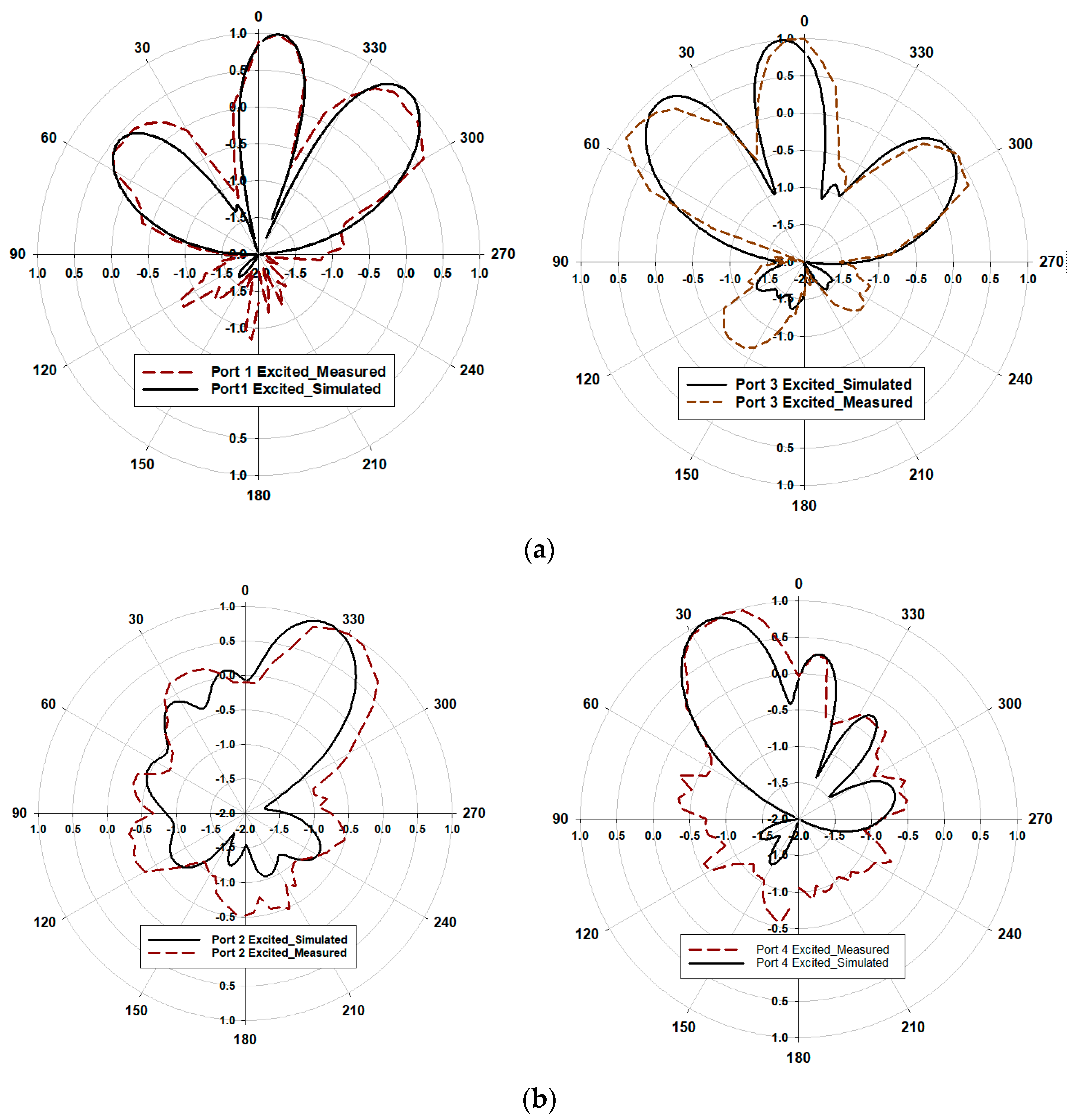
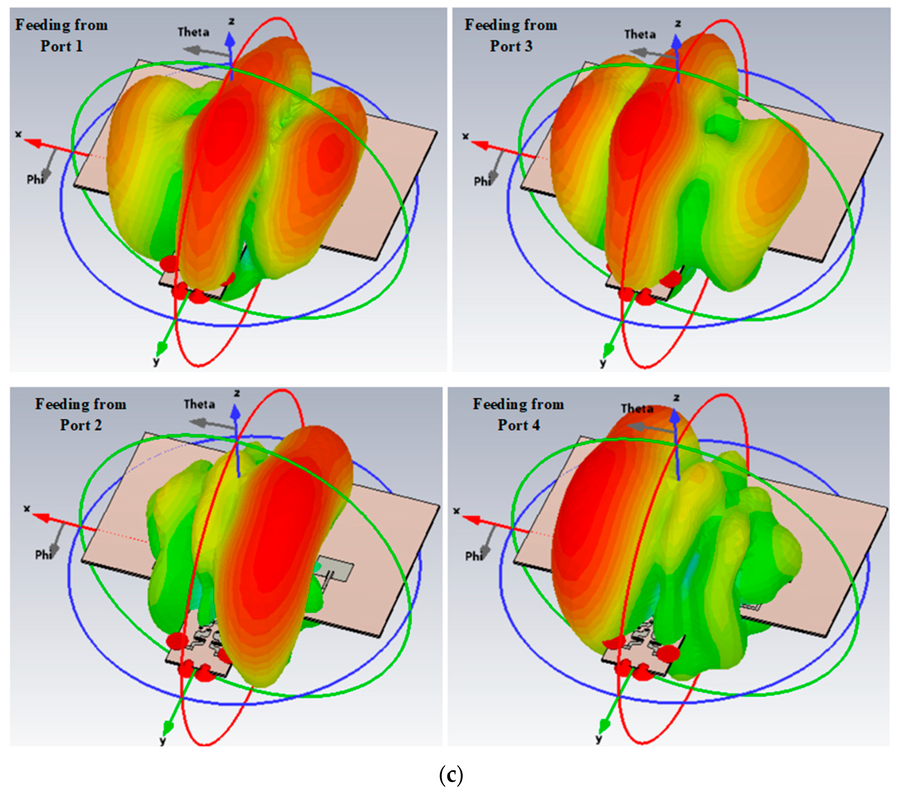
Figure 12 illustrates the simulated and measured normalized elevation-plane radiation patterns at 6.5 GHz for different excitation ports. The results indicate that the main beam direction is dependent on the active input port. Specifically, when ports 1 and 3 are excited, the main lobes are observed at 6° and −7°, with corresponding gains of 6.66 dB and 6.89 dB, respectively. However, in both cases, an additional lobe appears with a magnitude comparable to that of the main lobe directed at 42° and −43°, respectively, as shown in Figure 12a. These additional lobes are attributed to the power imbalance at the output ports when the network is excited through these specific inputs. Since grating lobes may arise from practical feeding network imperfections (such as phase shift errors and unequal power division) and the interaction between closely spaced elements can distort amplitude and phase, leading to unintended side lobe growth, mitigation strategies are required. One possible approach is to ensure equal power distribution at the output ports. This can be achieved by selecting an appropriate substrate material, as substrate properties significantly influence power balance; however, in this design, a cost-effective substrate was chosen. Another approach involves minimizing mutual coupling between antenna elements through specialized techniques, thereby reducing amplitude and phase distortions. Nonetheless, this phenomenon appears to introduce a beneficial characteristic to the feeding network, as it enables an extended beam steering range of up to ±43°, albeit at the expense of reduced main beam gain.
However, when the beamforming network is excited through ports 2 and 4, the radiation patterns exhibit main lobe directions at ±24°, with corresponding gains of 9.96 dB and 9.36 dB, respectively, as shown in Figure 12b. In this case, the simulated gain is observed to be 9.69 dB and 9.36 dB for ports 2 and 4, respectively, which are higher values compared to the gain obtained from ports 1 and 3. This is expected, as the excitation from ports 1 and 3 results in three major lobes, two of which are closely spaced. In contrast, excitation from ports 2 and 4 produces a single main lobe. Although some back lobes are present, they appear to be more pronounced in the measured results than in the simulated ones. This discrepancy contributes to the measured gain being lower than the simulated gain in these two cases, as summarized in Table 6.
To provide a clearer illustration of how the radiation pattern is formed under excitation from different input ports, the 3D radiation pattern is presented as shown in Figure 12c. Finally, the details of the simulated and measured radiation patterns for the four beam angles, along with the corresponding gains for various input port excitations at 6.5 GHz, are shown in Table 6.
Table 6 presents the radiation characteristics of the four-element conventional microstrip antenna array connected to the proposed feeding network. It shows that when the excitation is applied through ports 1 and 3, the average maximum beam angle is approximately ±5°, whereas for ports 2 and 4, the average simulated maximum beam angle shifts to approximately ±25°. The measured beam directions deviate from the simulated ones by up to ±4° at most.
In terms of gain, ports 2 and 4 exhibit higher values than ports 1 and 3 due to the absence of minor lobes in the former case. Additionally, the measured gain for ports 2 and 4 is slightly lower than the simulated gain, which can be attributed to the presence of some back lobes in the measured radiation pattern.
Finally, the design demonstrates a relatively consistent radiation efficiency across all ports, with an average of approximately 83%.

5. Conclusions

This paper presented the design of a novel compact BM based on a quasi-twisted branch line coupler (QBLC). The QBLC employs a two-layer configuration separated by a shared ground plane, which not only facilitates significant miniaturization of the BLC but also allows the reuse of the same substrate structure. This architectural innovation eliminated the need for conventional crossovers, enabling the use of simple interconnections to route signals between the various sections of the BM. As a result, the overall size of the BLC was reduced by 92.5% compared to traditional designs.
The proposed BM exhibited excellent scattering parameters, including a return loss below −10 dB, an isolation coefficient better than −20 dB, and a transmission loss of −6.5 dB at the resonance frequency of 6.5 GHz. To demonstrate the practical applicability of the design as a feeding network for antenna arrays, the BM was integrated with a four-element antenna array. The system successfully achieved beam steering in multiple directions: −5°, +6°, +26°, −24°, +43°, and −43°. These results highlight the proposed BM as a promising candidate for sub-6 GHz 5G communication systems.

Author Contributions

F.H.A.: conceptual design, simulation, measurements, and writing; S.K.K.: supervision and writing. All authors have read and agreed to the published version of the manuscript.

Funding

This research received no external funding.

Institutional Review Board Statement

Not applicable.

Informed Consent Statement

Not applicable.

Data Availability Statement

Data are contained within the article.

Conflicts of Interest

The authors declare no conflicts of interest.

References

  1. Andrews, J.G.; Buzzi, S.; Choi, W.; Hanly, S.V.; Lozano, A.; Soong, A.C.K. What will 5G be? IEEE J. Sel. Areas Commun. 2014, 32, 1065–1082. [Google Scholar] [CrossRef]
  2. Vallappil, A.K.; Rahim, M.K.A.; Khawaja, B.A.; Iqbal, M.N. Compact metamaterial based 4 × 4 butler matrix with improved bandwidth for 5G applications. IEEE Access 2020, 8, 3573–13583. [Google Scholar]
  3. Ojaroudi Parchin, N.; Alibakhshikenari, M.; Jahanbakhsh Basherlou, H.; Abd-Alhameed, R.A.; Rodriguez, J.; Limiti, E. MM-Wave Phased Array Quasi-Yagi Antenna for the Upcoming 5G Cellular Communications. Appl. Sci. 2019, 9, 978. [Google Scholar] [CrossRef]
  4. Kim, S.; Yoon, S.; Lee, Y.; Shin, H. A Miniaturized Butler Matrix Based Switched Beamforming Antenna System in a Two-Layer Hybrid Stackup Substrate for 5G Applications. Electronics 2019, 8, 1232. [Google Scholar] [CrossRef]
  5. Lialios, D.I.; Ntetsikas, N.; Paschaloudis, K.D.; Zekios, C.L.; Georgakopoulos, S.V.; Kyriacou, G.A. Design of True Time Delay Millimeter Wave Beamformers for 5G Multibeam Phased Arrays. Electronics 2020, 9, 1331. [Google Scholar] [CrossRef]
  6. Lee, S.; Lee, Y.; Shin, H. A 28-GHz Switched-Beam Antenna with Integrated Butler Matrix and Switch for 5G Applications. Sensors 2021, 21, 5128. [Google Scholar] [CrossRef] [PubMed]
  7. Ahmed, F.H.; Saad, R.; Khamas, S.K. A Novel Compact Broadband Quasi-Twisted Branch Line Coupler Based on a Double-Layered Microstrip Line. Micromachines 2024, 15, 142. [Google Scholar] [CrossRef] [PubMed]
  8. Bhowmik, P.; Moyra, T. Modelling and validation of a compact planar Butler matrix by removing crossover. Wirel. Pers. Commun. 2017, 95, 5121–5132. [Google Scholar] [CrossRef]
  9. Jizat, N.; Rahim, S.K.; Nor, M.Z.; Abdulrahman, Y.; Sabran, M.I.; Jamlos, M.F. Beamforming network using dual band-dual beam reduced size Butler Matrices. Radioengineering 2013, 22, 769. [Google Scholar]
  10. Du, M.; Peng, H. Ultra-compact electromagnetic metamaterial transmission line and its application in miniaturized butler matrix. Prog. Electromagn. Res. C 2014, 55, 187–197. [Google Scholar] [CrossRef]
  11. Zhai, Y.; Fang, X.; Ding, K.; He, F. Miniaturization Design for 8 × 8 Butler Matrix Based on Back-to-Back Bilayer Microstrip. Int. J. Antennas Propag. 2014, 2014, 583903. [Google Scholar] [CrossRef]
  12. Khan, S.; Bashir, A.; Ali, H.; Rauf, A.; Marey, M.; Mostafa, H.; Syed, A.I. Compact 28 GHz Millimeter Wave Antenna for Future Wireless Communication. Comput. Mater. Contin. 2022, 72, 302–314. [Google Scholar] [CrossRef]
  13. Shallah, A.B.; Zubir, F.; Rahim, M.K.A.; Jizat, N.M.; Basit, A.; Assaad, M. A Miniaturized Metamaterial-Based Dual-Band 4 × 4 Butler Matrix With Enhanced Frequency Ratio for Sub-6 GHz 5G Applications. IEEE Access 2024, 12, 32320–32333. [Google Scholar] [CrossRef]
  14. Barro, O.A.; Himdi, M. Single Layered 4 × 4 Butler Matrix Without Phase-Shifters and Crossovers. IEEE Access 2018, 6, 77289–77298. [Google Scholar]
  15. Pozar, D.M. Microwave Engineering, 4th ed.; John Wiley & Sons, Inc: Hoboken, NJ, USA, 2012; pp. 26–30. [Google Scholar]
  16. Chen, C.H.; Wu, H.; Wu, W. Design and implementation of a compact planar 4 × 4 microstrip Butler matrix for wideband application. Prog. Electromagn. Res. C 2011, 24, 43–55. [Google Scholar] [CrossRef]
  17. Balanis, C.A. Antenna Theory: Analysis and Design; John Wiley & Sons, Inc: Hoboken, NJ, USA, 2016. [Google Scholar]
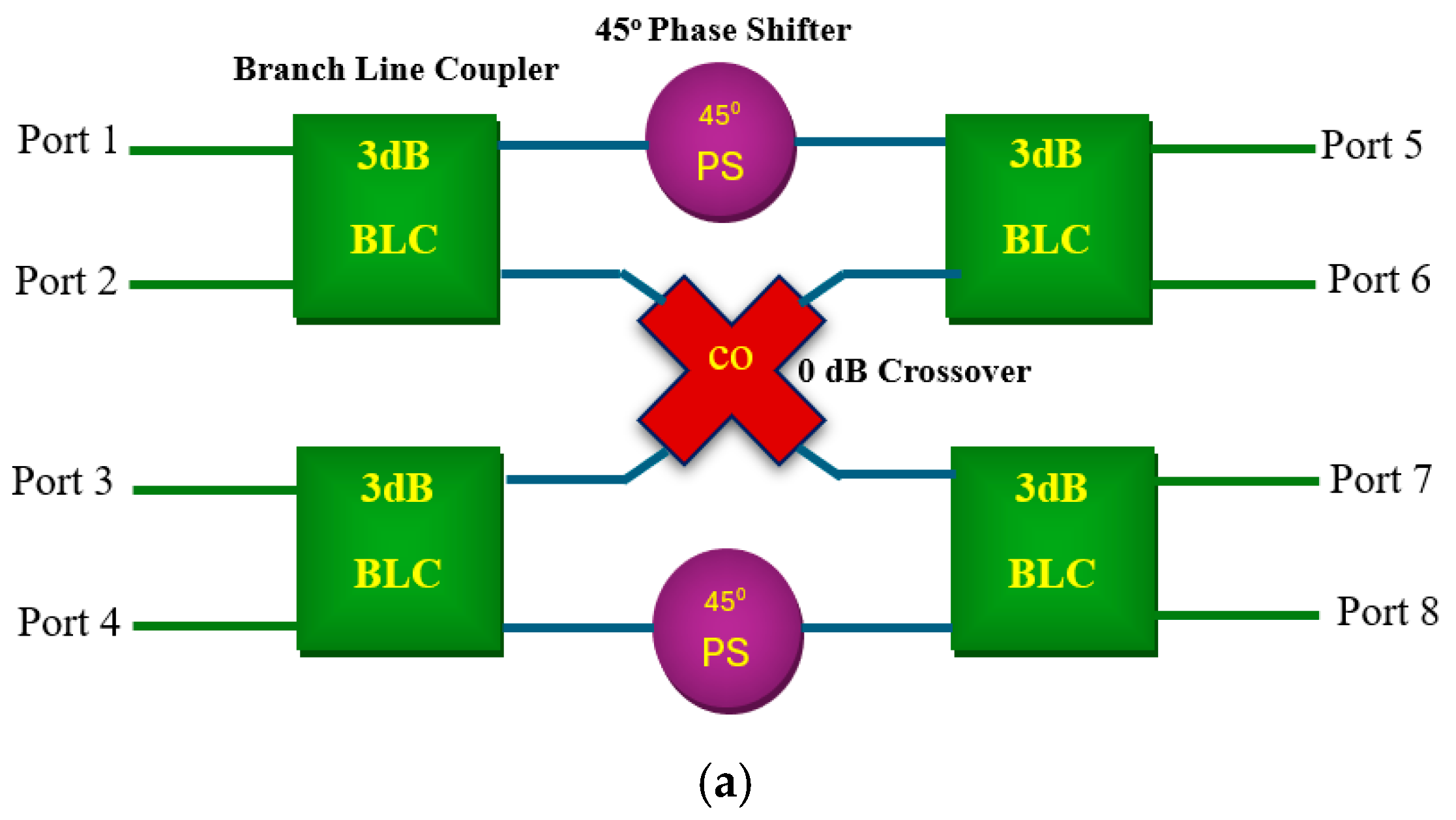
Figure 1. (a) Circuit layout of the conventional 4 × 4 Butler matrix, and (b) circuit layout of the conventional 4 × 4 Butler matrix connected to a 1 × 4 array antenna.
Electronics 14 03565 g001aElectronics 14 03565 g001b
Figure 2. Reference quasi-twisted branch line coupler: (a) perspective view; and (b) frame mode view.
Electronics 14 03565 g002
Figure 3. Scattering parameters of the referenced BLC: (a) S11, (b) S21, (c) S31, and (d) phase difference in the output power [7].
Electronics 14 03565 g003
Figure 4. Proposed compact quasi-twisted BM: (a) frame mode view; and (b) top and bottom views of the circuit diagram.
Electronics 14 03565 g004
Figure 5. (a) Proposed Butler matrix network prototype; and (b) truncated Butler matrix prototype for SMA connection.
Electronics 14 03565 g005
Figure 6. (a) S-parameter measurement setup, and (b) 50 Ω terminator connections.
Electronics 14 03565 g006
Figure 7. Proposed compact BM—parameter results for input port 1: (a) S11; (b) transmission loss (S51, S61, S71, and S81); (c) isolation coefficients (S21, S31, and S41); and (d) phase angles of transmission coefficients (∠S51, ∠S61, ∠S71, and ∠S81).
Electronics 14 03565 g007aElectronics 14 03565 g007b
Figure 8. Proposed compact BM—parameter results for input port 2: (a) S22; (b) transmission loss (S52, S62, S72, and S82); (c) isolation coefficients (S12, S32, and S42); and (d) phase angles of transmission coefficients (∠S52, ∠S62, ∠S72, and ∠S82).
Electronics 14 03565 g008aElectronics 14 03565 g008b
Figure 9. Prototype of an array antenna connected to the proposed Butler matrix network: (a) top view, (b) bottom view.
Electronics 14 03565 g009
Figure 10. (a) Radiation pattern measurement setup in an anechoic chamber. (b) Antenna alignment using a laser.
Electronics 14 03565 g010
Figure 11. Return loss of the phased array antenna connected to the proposed Butler matrix network: (a) S11, (b) S22.
Electronics 14 03565 g011
Figure 12. Comparison between measured and simulated elevation normalized radiation patterns: (a) excitation from ports 1 and 3, (b) excitation from ports 2 and 4, and (c) simulated 3D view.
Electronics 14 03565 g012aElectronics 14 03565 g012b
Table 1. Output phase response of conventional Butler matrix.
Input Port 1Input Port 2Input Port 3Input Port 4
Output port 5 ( θ 1 )135°45°90°
Output port 6 ( θ 2 )90°180°−45°45°
Output port 7 ( θ 3 )45°−45°180°90°
Output port 8 ( θ 4 )90°−45°135°
Phase difference between consecutive output port−45°+135°−135°+45°
Table 2. Phase difference between conventional and proposed BM designs due to additional length at the input/output ports.
Input Port 1Input Port 2Input Port 3Input Port 4
S 5 35.9155.169.8129.6
S 6 155.198.7129.610
S 7 60.4123.835.9155.1
S 8 123.810154.198.7
Table 3. Additional physical lengths required at the input/output ports to align the phase of the proposed BM with that of the conventional BM.
Input Port 1Input Port 2Input Port 3Input Port 4
L 5 (mm)3.0112.995.8510.85
L 6 (mm)12.998.2710.850.84
L 7 (mm)5.0510.373.0112.99
L 8 (mm)10.370.8412.918.27
Table 4. Scattering parameter details for the proposed compact BM with excitation from ports 1 and 2.
Scattering ParametersPort 1Port 2
Sim.Mea. Sim.Mea.
Return Loss (dB)S11−19.8−16S22−21.9−12.35
Transmission
Coefficients
(dB)
S51−8−8.8S52−6.25−7
S61−6.48−4.64S62−6.13−5.65
S71−5.85−7.1S72−6.48−6.4
S81−6.53−5.77S82−7.9−8.4
Isolation Coefficients
(dB)
S21−19.19−20.4S12−19−31
S31−27.66−26.7S32−26.6−29.9
S41−27.9−28.8S42−26.2−24.6
Transmission Coefficient Phases
(deg.)
∠S5113.0815.2∠S5241.745.7
∠S6141.956.8∠S6272.383.1
∠S7189.2103.4∠S72−62.14−56.9
∠S81−61.9−44∠S82146.4140.9
Table 5. Comparison of the proposed BM parameters and size with previous literature.
RefMatrix SizeTechnologyCenter Frq. GHzBandwidth (%)Insertion loss (dB)Isolation
(dB)
Physical Area (mm2)Reduction (%)
[16]4 × 4lumped-distributed 5207.518109 × 9950
[9]4 × 4Meandering2.4/5.818.42/15.58.9/10.916.8/25.196 × 12563
[10]4 × 4EM-MTM TLs0.86/7.228.7109 × 8980.9
[13]4 × 4CRLH-TL3.4714.67 ± 21470 × 73.775
[2]4 × 4Adding stubs6.587.520130 × 7342.6
This Work4 × 4Quasi-2 Twisted BLC6.5156.52013.8 × 38.892.5
Table 6. Radiation parameters of the four-element antenna array fed by the proposed compact BM.
Input PortMaximum Beam DirectionGainSimulated Radiation Efficiency
Meas.Simu.Meas.Simu.
Port 1−5−56.586.6782.8%
Port 2−30−249.179.6983.6%
Port 3366.76.8982.9%
Port 420249.29.3683.6%
Disclaimer/Publisher’s Note: The statements, opinions and data contained in all publications are solely those of the individual author(s) and contributor(s) and not of MDPI and/or the editor(s). MDPI and/or the editor(s) disclaim responsibility for any injury to people or property resulting from any ideas, methods, instructions or products referred to in the content.