Abstract
The Dynamic Voltage Restorer (DVR), which is connected in series between the power grid and the load, can rapidly compensate for voltage disturbances to maintain stable voltage at the load end. To enhance the energy supply capacity of the DVR and utilize its shared circuit topology with photovoltaic (PV) inverters—which enables the dual functions of voltage compensation and PV-storage power generation—this study integrates PV and energy storage as a coordinated energy unit into the DVR, forming a PV-storage-integrated DVR system. The core innovation of this system lies in extending the voltage disturbance detection capability of the DVR to include harmonics. By incorporating a Butterworth filtering module and voltage fluctuation tracking technology, high-precision disturbance identification is achieved, thereby supporting power balance control and functional coordination. Furthermore, a multi-mode-power coordinated regulation method is proposed, enabling dynamic switching between operating modes based on PV output. Simulation and experimental results demonstrate that the proposed system and strategy enable smooth mode transitions. This approach not only ensures reliable voltage compensation for sensitive loads but also enhances the grid-support capability of PV systems, offering an innovative technical solution for the integration of renewable energy and power quality management.
1. Introduction
Voltage sags and swells represent some of the most critical power quality challenges in modern power systems [1,2,3]. These disturbances pose significant threats to the safe operation of sensitive industrial loads, such as precision machining equipment and automated control systems, making them an active area of research in the international power engineering community. According to the International Electrotechnical Commission standard IEC 61000-4-30 [4], a voltage sag is defined as a sudden reduction in the RMS voltage to between 10% and 90% of the rated value for durations ranging from 0.5 cycles to 1 min [5,6,7]. Similarly, a voltage swell is characterized by an increase in the RMS voltage to 110–180% of the nominal value, with the same duration range as sags. These precise definitions establish a unified basis for studying and managing voltage fluctuations [8,9,10,11]. The ongoing attention from authoritative organizations, including the International Council on Large Electric Systems (CIGRE) and the Institute of Electrical and Electronics Engineers (IEEE), further underscores the importance of these issues. The Dynamic Voltage Restorer (DVR) [12,13], which serves as a critical power electronic device for mitigating voltage sags, swells, and transient interruptions, is connected in series between the power grid and the load. It rapidly and effectively compensates for grid voltage anomalies, thereby protecting sensitive equipment from voltage fluctuations and playing a vital role in ensuring the stable operation of critical loads. Conventional DVRs typically employ energy storage batteries as the DC-link energy source and utilize inverters for precise voltage control. These systems exhibit high energy conversion efficiency, compatibility with power systems of various scales, and the ability to handle diverse voltage disturbances such as sags, swells, and flickers, demonstrating considerable operational flexibility [14]. In recent years, with the rapid advancement of renewable energy technologies, there has been growing interest in integrating photovoltaic (PV) generation into the DC side of the DVR as an alternative to traditional energy storage. This integration not only diversifies the energy supply for the DVR but also leverages the structural similarities between DVRs and PV inverters, enabling dual operational modes: voltage compensation and PV power generation with storage. This approach holds significant potential for enhancing renewable energy utilization and advancing power quality management. Traditional DVR compensation strategies struggle to balance energy consumption and duration. Li et al. [15,16] proposed an Energy-Optimal Compensation (EOC) strategy that dynamically switches between energy-minimization and pre-sag compensation modes based on sag depth, incorporating voltage limiting to optimize performance under complex voltage quality issues. Phase delay in voltage detection critically affects DVR accuracy. Ko [17] developed a circular multi-pointer memory filter using equivalent-time sampling and phase-shift techniques to eliminate analog filter lag, enabling delay-free, high-precision voltage measurement with low computational cost—ideal for feedforward control. To simplify PI controller tuning in DVRs, Ibrahim et al. applied the Artificial Rabbits Optimization (ARO) algorithm. The ARO-tuned controller improves dynamic response and reduces output voltage THD, demonstrating AI’s strong potential for enhancing DVR robustness and compensation quality [17,18].
However, existing studies still exhibit three major limitations. First, the output of photovoltaic (PV) power generation is highly stochastic and intermittent due to factors such as solar irradiance and ambient temperature [19], making it challenging to sustain the power balance of the PV-storage DVR system and often compromising the response speed and accuracy of voltage compensation. Second, grid voltage fluctuations are frequently accompanied by harmonic pollution; however, most PV-storage DVR control strategies fail to incorporate harmonics into a unified detection and compensation framework, leading to unsatisfactory compensation performance under complex grid conditions. Third, conventional phase-locked loops (PLLs) struggle to accurately extract the positive-sequence component under distorted voltage conditions [20], which compromises the accuracy of voltage detection and adversely affects the precision of compensation command generation.
To address the aforementioned challenges, this paper focuses on the optimal design of a photovoltaic-storage integrated DVR system, with the aim of enhancing its performance under complex grid conditions through advancements in control strategies and detection methodologies. Specifically, the contributions include the following:
- (1)
- Developing a voltage detection model that incorporates harmonics based on instantaneous reactive power theory and enabling high-accuracy identification of voltage parameters through a combination of a software phase-locked loop (SPLL) and a Butterworth filtering algorithm;
- (2)
- Designing a multi-mode power coordination strategy to dynamically switch operating modes according to PV power generation, enabling a balance between energy utilization and compensation requirements;
- (3)
- Validating the effectiveness of the proposed approach through detailed simulation studies.
The key innovations of this work are primarily reflected in the following aspects:
- (1)
- The incorporation of harmonic components into a unified detection framework for the PV-storage DVR system and the introduction of a composite detection method combining SPLL with Butterworth filtering, leading to a significant improvement in parameter identification accuracy under distorted voltage conditions;
- (2)
- The development of an adaptive multi-mode switching strategy based on real-time PV output, which facilitates seamless coordination between voltage compensation and PV-storage operation and effectively addresses the power balance challenge inherent in conventional systems;
- (3)
- A comprehensive demonstration of the stability and efficiency of the proposed system under combined scenarios of voltage sags, swells, and harmonics, offering a new technical pathway for the deep integration of renewable energy and power quality management.
2. Construction of Fast-Response System for Photovoltaic Energy Storage Based on Dynamic Voltage Restorer
The schematic diagram of the DVR is shown in Figure 1. The Dynamic Voltage Restorer (DVR) is a power-quality device connected in series between the power grid and the customer, designed to enhance voltage quality in electrical systems. It is primarily employed to protect voltage-sensitive loads from short-duration voltage disturbances such as sags and momentary fluctuations. Over time, the structure of the DVR has undergone continuous development and refinement in both theoretical research and engineering practice. Nevertheless, the fundamental configuration of the DVR has remained consistent; a schematic diagram of the typical DVR topology is presented in Figure 1.
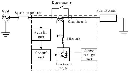
Figure 1.
DVR schematic.
The Dynamic Voltage Restorer (DVR) operates in two primary modes. In its compensation mode, when a grid voltage disturbance occurs, the bypass switch Ks is opened to integrate the DVR into the circuit. The DVR then injects a compensating voltage through the coupling transformer, which superimposes with the grid voltage to maintain the voltage across sensitive loads within the allowable range. A schematic diagram of this operating structure is shown in Figure 2.
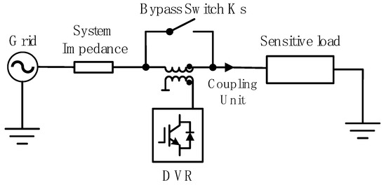
Figure 2.
Operating mode.
Bypass mode: During grid voltage fluctuations that do not require compensation for the sensitive loads, the bypass switch Ks remains closed. In this state, the DVR is bypassed from the compensation circuit and remains inactive, with its structure as illustrated in Figure 3.
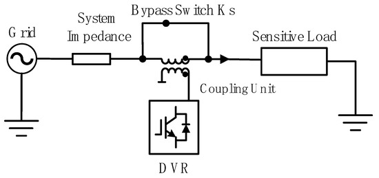
Figure 3.
Bypass mode.
The main modules of the Dynamic Voltage Restorer primarily consist of: the energy storage unit, the inverter unit, the filtering unit, and the coupling unit. A schematic diagram of its structure is provided in Figure 4.
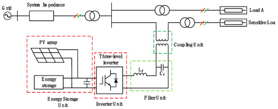
Figure 4.
Dynamic Voltage Restorer structure.
The capacity of the energy storage unit is a key factor in determining the compensation duration of the Dynamic Voltage Restorer, making the selection of a suitable and well-sized energy storage system essential. In distributed energy applications, renewable energy sources are often integrated with storage batteries—for instance, through a combined strategy of wind power generation and batteries, or using photovoltaic (PV) arrays coupled with batteries as the DC-side energy supply unit for the DVR. This approach overcomes the limitation of traditional battery-only DVR systems, which often suffer from short compensation times. In this paper, a hybrid energy storage system consisting of a PV system and a battery (DVR-BES-PV) is adopted.
- (1)
- Mathematical Modeling of the Photovoltaic System and Battery
The equivalent circuit of the photovoltaic cell is shown in Figure 5, and the parameters of its equivalent model are summarized in Table 1.
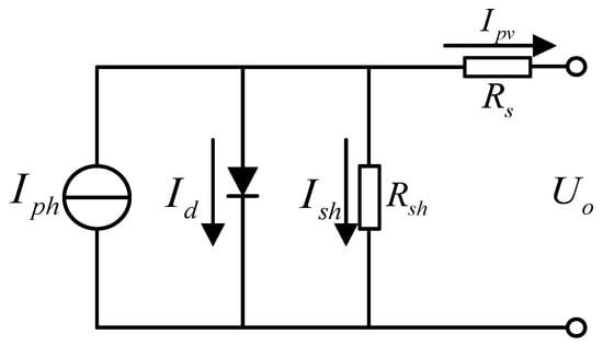
Figure 5.
Equivalent circuit diagram of a photovoltaic cell.

Table 1.
Equivalent model specific parameters.
The internal relational equation of the PV array is as follows:
where is the diode forward saturation current, with the magnitude of its value being independent of the light intensity; is the electrical charge, ; is the diode equivalent voltage; A is the PN junction constant inside a photovoltaic cell; K is the Boltzmann’s constant; is the difference between the actual and reference temperatures of photovoltaic cells; and are two different light intensities.
- (2)
- Control Algorithm for Photovoltaic Power Generation
Photovoltaic (PV) cells are influenced by factors such as light intensity and temperature, among others. The output characteristics of PV modules are strongly influenced by changes in irradiance and temperature, leading to voltages, currents, and powers that exhibit a pronounced nonlinear relationship. To ensure that PV arrays operate optimally under varying conditions, consistently deliver maximum power, and minimize energy loss, a control technique known as Maximum Power Point Tracking (MPPT) was developed. Among the well-established and widely adopted MPPT methods are the Perturb and Observe method and the Incremental Conductance method. A schematic of the control algorithm for both methods is provided in Figure 6.

Figure 6.
Equivalent circuit diagram of a photovoltaic cell.
The Perturb and Observe method, also referred to as the hill-climbing method, operates by periodically applying a small perturbation to the output voltage or current of the PV array and then comparing the resulting change in output power. As illustrated in the left panel of Figure 6, this process involves adjusting the operating point based on the power variation: if the power increases, the perturbation continues in the same direction; if it decreases, the direction of perturbation is reversed. This iterative process enables the PV system to converge toward the maximum power point. A simulation model of the Perturb and Observe method is shown in Figure 7.

Figure 7.
Simulation model diagram of the perturbation observation method.
The Incremental Conductance method is based on the power–voltage (P–V) characteristic curve of the PV cell. It operates by differentiating the power with respect to voltage and using the sign of the derivative (dP/dV) to determine the relative position of the operating point with respect to the maximum power point (MPP). Specifically, when dP/dV = 0, the operating point is at the MPP; when dP/dV > 0, it is to the left of the MPP and the voltage should be increased; and when dP/dV < 0, it is to the right of the MPP and the voltage should be decreased. This process is repeated iteratively until the MPP is reached. A simulation model of the Incremental Conductance method is presented in Figure 8.
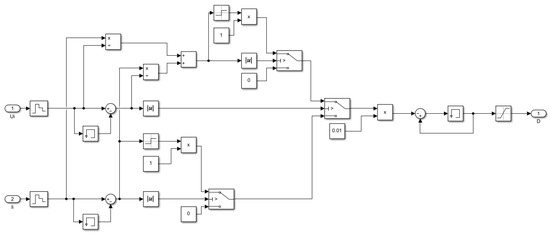
Figure 8.
Conductance increment method simulation model diagram.
The relative merits and limitations of the two primary MPPT control algorithms were evaluated; a summary of this comparison is provided in Table 2.

Table 2.
Advantages and disadvantages of MPPT control algorithms.
- (3)
- Energy Storage Battery Unit
Due to the inherent intermittency and instability of photovoltaic power generation, which is highly dependent on solar irradiance, its output power fluctuates significantly with varying light conditions. The energy storage system serves to store surplus energy during periods of strong illumination, such as daytime, and releases the stored electricity during nighttime, cloudy days, or other conditions with low irradiance or power generation. Furthermore, the energy storage system improves the reliability and stability of the power supply. It can provide backup power in the event of grid failure, support islanded operation, and respond to unforeseen contingencies. Additionally, it facilitates flexible energy dispatch, integrates distributed energy resources, and supports grid peak shaving and valley filling.
The equivalent circuit of the battery is presented in Figure 9.
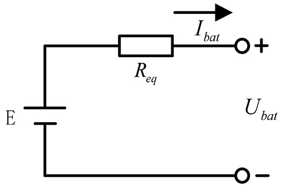
Figure 9.
Equivalent circuit diagram of energy storage battery.
It is obtained from Ohm’s law:
In Equation (6), is the electric potential of storage batteries, is the equivalent resistance of the battery, and is the discharge current of storage batteries. The electric potential is calculated as follows:
In Equation (7), , , and are energy storage battery charging and discharging curve fitting coefficients, is the rated capacity of the battery, and is the actual discharge capacity of the battery.
The State of Charge (SOC) of the battery exerts a considerable influence on both its own performance and that of associated systems, affecting critical parameters such as charge–discharge efficiency and output power. When the SOC is either excessively high or low, it results in diminished charging and discharging efficiency, compromised output power, and a reduction in usable capacity. Moreover, SOC is intrinsically linked to battery longevity; prolonged operation under extreme SOC conditions accelerates aging and shortens the battery’s life cycle. Therefore, it is imperative to establish appropriate upper and lower SOC thresholds to ensure system stability and reliable operation.
In Equation (8), is the lower limit of the state of charge of the storage battery, whose value is set to 20%, and is the upper limit of the charge state of the storage battery, and its value is set to 90%.
The three-phase, three-level Neutral Point Clamped (NPC) inverter (structure shown in Figure 10) is a high-performance power electronic converter based on multilevel topology. Its operating principle relies on dividing the DC bus voltage into three levels through the use of four sets of switching devices and two clamping diodes per phase leg. By appropriately combining the switching states, a stepped voltage waveform is generated that closely approximates a sinusoidal waveform.
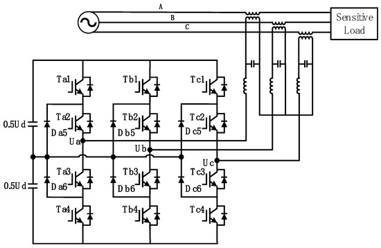
Figure 10.
Topology diagram of active midpoint clamped three-level NPC inverter circuit.
In the NPC-type three-level inverter, the voltage stress on each switching device during operation is half of the DC bus voltage, significantly enhancing the voltage and power-handling capability of the converter. Compared to conventional two-level topologies, this structure offers substantial performance benefits: first, it produces output line and phase voltages with an increased number of levels, which effectively reduces the total harmonic distortion (THD) of the voltage waveform; second, its switching losses are only 50% of those in a two-level inverter under the same DC voltage and phase current, enabling higher switching frequencies and further improved harmonic performance. The Dynamic Voltage Restorer (DVR) investigated in this study employs an NPC-type three-level inverter as its core power conversion topology.
The inverter circuit typically generates high-order harmonics during operation, necessitating a filter circuit to suppress these harmonic components. As shown in Figure 11, the filter can be installed at one of two locations: Position A (on the inverter output side) effectively filters high-frequency components immediately after inversion, while Position B (on the sensitive load side) prevents high-frequency noise or harmonics introduced by the DVR during voltage compensation from affecting downstream equipment. In this work, the active NPC three-level inverter used exhibits inherently low harmonic distortion; therefore, configuration C—placing the filter on the transformer side—is adopted. This design utilizes the leakage inductance of the coupling transformer to replace a dedicated filter inductor, requiring only an additional capacitor, thereby reducing hardware cost without compromising filtering performance.
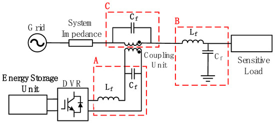
Figure 11.
Filter module installation location diagram.
The integration of the Dynamic Voltage Restorer (DVR) with the grid voltage typically employs two primary coupling methods: series transformer coupling and capacitor coupling (transcapacitor coupling), each exhibiting distinct characteristics in terms of performance and application. The corresponding structural diagrams are illustrated in Figure 12.

Figure 12.
Schematic diagram of the structure of the DVR coupled with grid voltage.
As illustrated in Figure 12A, the DVR is connected to the grid via a series transformer, through which the compensation voltage is injected. Additionally, the transformer turn ratio can be designed to reduce the required DC-link voltage level of the inverter while providing electrical isolation. The DVR system investigated in this paper employs series transformer coupling.
Figure 12B shows an alternative coupling method using capacitors, which offers a simpler structure and lower cost by eliminating the need for a transformer and reducing the installation footprint. However, the absence of galvanic isolation in this approach introduces potential safety risks.
Following the system configuration described in previous sections, a simulation model of the PV-storage-integrated DVR system was developed. To thoroughly evaluate the performance of the hybrid PV-storage DVR in addressing voltage sags, swells, and other disturbances, a comprehensive system was constructed, incorporating the PV generation model, the NPC inverter circuit, and the coupling unit. Subsequently, power quality issues were analyzed in detail, accounting for various practical influencing factors. Specific fault conditions common in DVR applications were designed, and simulation results were used to validate the effectiveness and feasibility of the proposed PV-storage DVR in providing reliable voltage compensation.
A variety of control strategies have been developed for Dynamic Voltage Restorers (DVRs). Among the classical methods, Proportional–Integral (PI) control [21] uses proportional and integral actions to regulate voltage, offering simplicity and reliability, though it suffers from slow dynamic response and poor adaptability to sudden load changes. Proportional–Resonant (PR) control [22] provides high gain at resonant frequency to eliminate steady-state error. In [23], a single-phase DVR with an elliptical restoration algorithm and dual-loop PR and PR with Sequence Decoupling Resonant (PRSDR) controllers in a stationary frame showed improved performance. Proportional–Integral–Derivative (PID) control combines three terms to dynamically adjust system input, maintaining the controlled variable near the reference with high flexibility. Beyond classical approaches, numerous advanced strategies have emerged. Optimal sliding mode control [24,25] enhances robustness and control performance through optimized surfaces and switching functions, maintaining stability under parameter variations and external disturbances while reducing steady-state error. References [26,27] proposed a momentum-adapted Fractional Least Mean Square (ma-FLMS) algorithm using a Fractional-Order PID (FOPID) controller optimized by an Autonomous Group Particle Swarm Optimizer (AGPSO), significantly improving dynamic response and steady-state accuracy. In [28], a strategy combining fractional calculus and an adaptive Variable Step-Size LMS (FMA VLMS) with a Fractional-Order PI (FOPI) controller was introduced. Its parameters were optimized via a Black Widow Optimization Algorithm (BWOA) to achieve optimal convergence and minimal steady-state error in DVR applications. These evolving strategies provide diverse pathways for enhancing DVR performance.
3. High-Precision Dynamic Voltage Recovery Control Strategy with Harmonic Suppression
As a core power quality management device, the Dynamic Voltage Restorer (DVR) not only mitigates voltage sags and swells but also plays a significant role in harmonic compensation. In a photovoltaic energy storage system integrated with a DVR, the quality of the control strategy critically influences system performance. In particular, a fast-response control method capable of harmonic suppression is essential.
This study employs instantaneous reactive power theory to detect grid voltage abnormalities and designs a software phase-locked loop (SPLL) to accurately track the grid voltage phase angle, thereby overcoming the limitations of conventional phase-locked loops under distorted voltage conditions. Furthermore, to suppress harmonics present in the transformed components after coordinate transformation, a Butterworth low-pass filter is introduced for high-precision harmonic attenuation. Based on these techniques, a rapid-response control architecture is established.
The proposed strategy ensures a swift system response to voltage sags and swells, effectively suppresses harmonic distortion, and achieves coordinated operation among the photovoltaic system, energy storage, and DVR functionality. Through this control framework, the system maintains stable and efficient performance even under complex grid conditions involving simultaneous voltage sags, swells, and harmonic pollution.
3.1. Voltage Fluctuation Extraction Based on Software Phase-Locked Loop (SPLL)
Traditional phase-locked loops (PLLs) achieve phase synchronization through hardware circuits by detecting zero-crossing points of the system voltage and typically employ a synchronous rotating coordinate transformation for phase locking. However, this method exhibits limited performance in highly distorted grid voltage environments, particularly under conditions such as phase jumps and three-phase imbalance. Under these scenarios, it often fails to accurately extract the positive-sequence components, leading to reduced response speed and accuracy of the phase-locking process.
To overcome these limitations, this study adopts a software phase-locked loop (SPLL) to replace the conventional hardware-based PLL. Owing to its superior adaptability and stability, the SPLL can operate reliably even in complex grid scenarios and significantly enhance the accuracy of positive-sequence component extraction.
Specifically, the SPLL implemented in this work combines the dq-transformation method with a PI control algorithm, forming a robust and precise phase-tracking system suitable for distorted voltage conditions.
Its working principle is shown in Figure 13. The three-phase voltage is transformed into the dq coordinate system to obtain and DC components. The difference between the DC component and the reference 0 value is processed through the PI link to obtain the error signal that needs to be tracked, which is then added to the fundamental wave angular frequency to obtain the angular frequency . Then, the phase angle output by the phase-locked loop is obtained through the PI link.
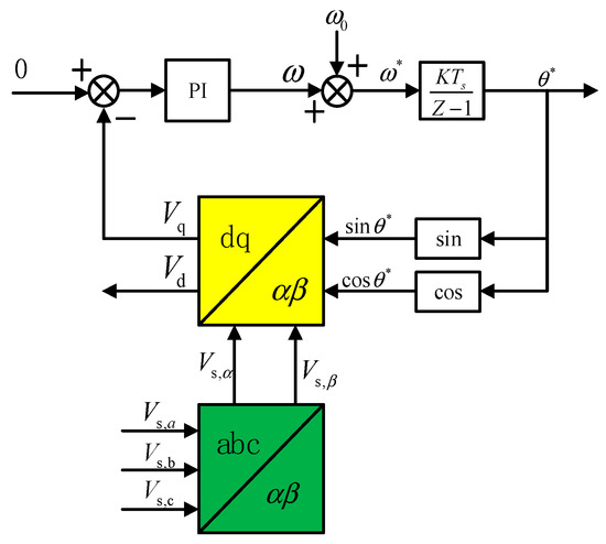
Figure 13.
Schematic diagram of SPLL.
Figure 14 shows the closed-loop control block diagram of the software phase-locked loop, where is the three-phase power frequency voltage cycle, is the proportional coefficient, and is the integral coefficient. Thus, the closed-loop transfer function of the software phase-locked loop is as follows:
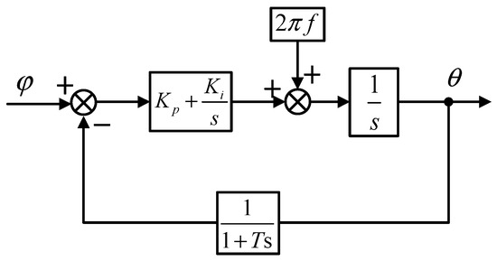
Figure 14.
Block diagram of SPLL closed-loop control.
In addition, the sufficient and necessary conditions for the stability of the system are obtained as follows:
For the frequency domain analysis of the SPLL closed-loop control system, by taking and , the Bode diagram shown in Figure 15 can be obtained.
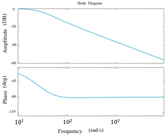
Figure 15.
Bode diagram of SPLL control system.
Through analysis, it can be seen that the software phase-locked loop system maintains stability, and its gain curve has similar characteristics to that of a low-pass filter.
3.2. High-Precision Grid Voltage Harmonic Extraction
After the coordinate transformation, the angular frequency of the positive-sequence component decreases, exhibiting low-frequency characteristics, while the negative-sequence component’s angular frequency increases, demonstrating high-frequency behavior. Therefore, a filter is required to eliminate the negative-sequence component and prevent voltage distortion. In addition, when a voltage sag occurs in the grid, the sagged voltage often contains high-order harmonic components, so it is necessary to further suppress these harmonics from the dq-axis components using a low-pass filter. The parameter configuration of the low-pass filter critically influences both the accuracy of signal decoupling and the dynamic response performance of the system.
Based on a frequency-domain impedance characteristics approach, a Butterworth filter is selected. This filter exhibits an approximately flat magnitude response in the passband. Although higher filter orders yield a flatter passband response, they also introduce increased group delay. Thus, a suitable order must be chosen to balance dynamic response speed and harmonic suppression effectiveness. In accordance with the IEEE 519-2014 harmonic standard [29], the target suppression frequency band is identified. The design process employs the magnitude-response constraint equation of the Butterworth filter and determines the minimal required order and cutoff frequency by considering both passband and stopband attenuation requirements.
The squared magnitude of the amplitude–frequency characteristic of the Butterworth filter is as follows:
where is the filter order, is the angular frequency, and is the cut-off frequency.
It is also necessary to meet the attenuation requirements of the passband and stopband. The passband constraint is as follows: at the passband cut-off frequency , the attenuation does not exceed (dB); the stopband constraint is as follows: at the stopband cut-off frequency , the attenuation is at least (dB). This is expressed by the following formulas:
Passband constraint equation:
Stopband constraint equation:
By taking the logarithm of Equations (12) and (13) and dividing them, is eliminated, to obtain
Then, the inequality related to the filter order is obtained:
N takes the smallest integer that satisfies the condition.
Then, we substitute into the passband constraint equation to calculate :
After repeated calculations, it is found that when the designed passband cut-off frequency = 1 rad/s, the maximum attenuation = 3 dB, the stopband cut-off frequency = 2 rad/s, and the minimum attenuation = 15 dB, the calculated filter order and cut-off frequency are
Taking the positive integer , then . The normalized frequency curve of the Butterworth filter is compared, as shown in Figure 16 below.
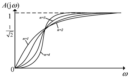
Figure 16.
Normalized amplitude–frequency response curve of Butterworth high-pass filter.
After simulation analysis, it is determined that the order of the Butterworth filter is 3; the Simulink software is then used to verify that the system has the performance of quickly compensating voltage fluctuations and reducing the total harmonic distortion to less than the limit defined in the IEEE 519 standard [29].
3.3. Power Coordination Regulation Control Method for Dynamic Voltage Restorer Based on Vector Angle Control Strategy
This paper proposes a power coordination control method for Dynamic Voltage Restorers based on a vector angle control strategy. The method establishes a multi-mode power coordination mechanism between the PV storage system, the grid, and the load, dividing the system operation into multiple modes tailored to power coordination under varying solar irradiance levels, and analyzes the active power transfer in each mode. The proposed multi-mode coordination strategy enables smooth transitions between grid-dominant, PV-storage-dominant, and grid feedback modes in real time, by adjusting the vector angle according to changes in PV output. This significantly improves the energy utilization of the PV storage system and enhances its active support capability for the grid. Given that the system uses PV storage as the DC source—which enables high-magnitude compensation—the pre-sag compensation method is adopted. This strategy is considered ideal for DVRs. Through precise calculation and control, it quickly determines the magnitude and phase of the compensation voltage required for injection. The core objective of this approach is to fully restore the load-side voltage to its pre-fault condition, thereby eliminating the impact of voltage sags, swells, and other power quality issues. A phasor diagram illustrating the characteristics of the pre-sag compensation strategy is shown in Figure 17.
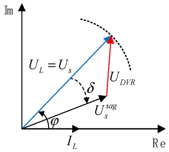
Figure 17.
Phasor diagram of the pre-sag compensation strategy.
Vector control is an advanced control technique that achieves precise regulation of power transfer among the grid, PV storage units, and the load by dynamically adjusting the phase angle of the load-side voltage. The core of this strategy lies in modulating the phase angle to dynamically control the output power from the PV storage system. Under low solar irradiance, the grid preferentially supplies the load while enabling energy feedback from storage. Under moderate irradiance, power complementation between the PV storage system and the grid improves utilization efficiency. Under strong irradiance, the PV storage system dominates power output and feeds surplus energy back to the grid, thereby reducing grid burden and providing effective grid support.
Figure 18 shows the schematic phasor diagram of the vector angle control. Using the phase angle of the grid voltage as the reference, denotes the phase angle of the load voltage, and represents the load power factor angle. Figure 18a illustrates the scenario under normal grid voltage without any fluctuation. By controlling the phase angle of the load voltage, the PV-storage DC source is inverted through a three-level inverter topology to output a specific voltage value. This method enables power transfer control across the entire DVR system while maintaining stable load voltage, thereby improving the utilization of energy from the PV storage side. Figure 18b depicts the situation when grid voltage fluctuates, such as the sagging or swelling of certain values, and . While the DVR’s compensation function operates normally and the load-side voltage remains constant, controlling the phase angle of the load voltage achieves overall system power transfer, ultimately maximizing the utilization of energy on the DC side.
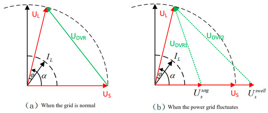
Figure 18.
Schematic phasor diagram of vector angle control.
4. Simulation and Analysis of Dynamic Photovoltaic Tuned Energy Storage System
The overall simulation model of the PV-storage-integrated DVR system is shown in Figure 19. It comprises the grid module, the inverter module, the PV storage unit, and the voltage coupling module.
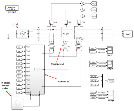
Figure 19.
DVR simulation model based on photovoltaic energy storage.
Photovoltaic Module Model
The simulation diagram of the PV unit is shown in Figure 20, which includes the PV array (with specific parameters provided in Table 3), a Boost converter circuit, and a PWM modulation module. The incremental conductance method is adopted as the MPPT algorithm in this study, which enables a fast response to variations in environmental conditions and achieves accurate maximum power point tracking performance.

Figure 20.
Photovoltaic module simulation model diagram.

Table 3.
Analysis of dynamic response results.
The simulation model of the energy storage unit is shown in Figure 21, which comprises the energy storage battery, a bidirectional DC/DC converter, and a control unit.
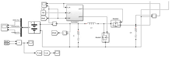
Figure 21.
Simulation model diagram of energy storage battery.
The workflow of the Dynamic Voltage Restorer (DVR) can be summarized as follows, with the sequence illustrated in Figure 22. The process begins with the acquisition of the grid voltage, which is compared to the fundamental voltage reference. If no abnormality is detected, no action is taken. Otherwise, in the event of voltage fluctuations, the sag depth is calculated, and the corresponding compensation value is determined and sent to the control unit. The control unit then generates a signal to drive the inverter, which converts the DC power from the energy storage unit into AC power. This output is filtered to remove harmonics, and the compensated voltage is injected via the coupling unit. Finally, the compensation voltage is superimposed onto the grid voltage to mitigate the sag.
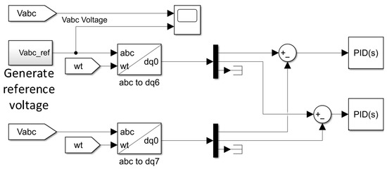
Figure 22.
Calculation model of voltage fluctuation error of DVR system.
Figure 23 and Figure 24 display the transient waveforms of the single-phase and three-phase grid voltages, respectively. In both cases, a voltage sag with a depth of 20% and a duration of 0.1 s is applied. Observation of the load voltage waveforms in both figures reveals that despite the occurrence of single-phase or three-phase voltage sags, the load voltage maintains a stable sinusoidal waveform after DVR compensation. These results verify that the proposed PV-storage-integrated DVR system can effectively compensate for both unbalanced and balanced voltage sags, thereby significantly enhancing system reliability.
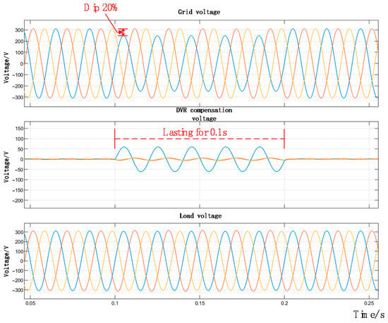
Figure 23.
Diagram showing 20% single-phase voltage drop.
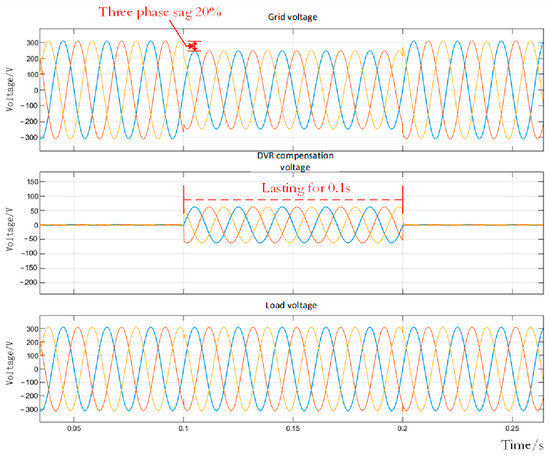
Figure 24.
Diagram showing 20% three-phase voltage drop.
To evaluate the ability of the PV-storage-integrated DVR system to effectively harness PV storage energy for voltage compensation—thereby maintaining stable and undisturbed load voltage under severe grid voltage sags—two test scenarios were designed and simulated: one with a 50% grid voltage dip and another with a 100% dip.
A three-phase symmetrical voltage sag occurs with a depth of 50% between 0.1 s and 0.2 s; the simulation results are shown in Figure 25. Once the detecting module identifies the grid abnormality, the compensation system is activated immediately to inject the required compensating voltage throughout the sag period (0.1 s to 0.2 s). During the voltage sag, the DC bus voltage remains stable at approximately 700 V, demonstrating the effective performance of the DC voltage stabilization on the energy storage side. In summary, the PV-storage-integrated DVR system rapidly compensates for the 50% grid voltage sag and maintains stable system operation.
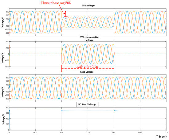
Figure 25.
Diagram showing 50% three-phase voltage drop.
When a three-phase symmetrical voltage sag occurs with a depth of 100%, as shown in Figure 26, the DVR remains in bypass mode and does not output compensation voltage under normal grid conditions. During the voltage sag from 0.1 s to 0.2 s, the DVR compensation system is triggered to inject the required compensating voltage, ensuring the load-side voltage remains stable. Meanwhile, the DC bus voltage regulator on the energy storage side maintains the DC link voltage around its nominal value without significant fluctuation, demonstrating effective voltage stabilization. In summary, the PV-storage-integrated DVR system successfully maintains constant load voltage during a 100% grid voltage sag, confirming the system’s robustness and operational effectiveness.
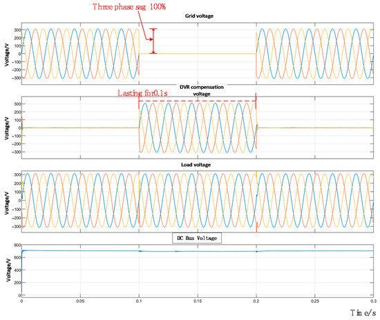
Figure 26.
Diagram showing 100% three-phase voltage drop.
5. Experimental Validation
This study focuses on the compensation strategy and performance of the Dynamic Voltage Restorer (DVR). In this section, the overall compensation capability of the DVR is experimentally validated using a bidirectional programmable DC source to emulate renewable energy integration and a programmable AC source to represent the grid, with the experimental setup illustrated in Figure 27.
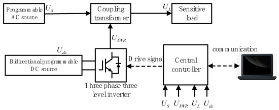
Figure 27.
Schematic diagram of experimental platform.
5.1. Dynamic Voltage Restorer Hardware Platform
As shown in Figure 28, the AC power source employed in the experiment is ACTIONPOWER’s PRE series regenerative programmable AC source (model PRE2020S), which is capable of simulating grid conditions and thus serves as the grid-emulating AC source for the DVR. The DC side uses a bidirectional programmable DC source to emulate the PV array.
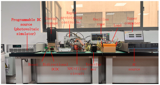
Figure 28.
Experimental platform related devices.
The inverter circuit utilizes three Infineon F3L75R07W2E3_B11 three-level single-phase arm modules. Each module incorporates four IGBTs and two diodes, with each gate driver supplied by an independent dual-output power module. The power modules operate in three-level mode, enabling an output voltage waveform that closely approximates a sinusoidal shape through appropriate control strategies. On the DC side of the inverter, two types of capacitors are employed: film capacitors and electrolytic capacitors. All capacitors are connected between the positive, negative, and neutral terminals. The large film capacitor has a capacitance of 110 μF, and the small film capacitor is 1 μF. The electrolytic capacitor bank consists of two series and four parallel units of 680 μF capacitors, resulting in a total equivalent capacitance of 1360 μF ± 20%.
The relay board employs JT105F-1 type relays, whose primary function is to provide isolation between low-power control signals and high-power circuits.
Additionally, they facilitate pre-charging of the bus capacitors during system startup. The relay’s switching operation is controlled via a level signal issued by the host computer, ensuring safe and managed energization of the DC bus.
The central controller is based on the YX-SPACE platform, which uses TI’s C2000 series DSP (F28377) as the core processor. The hardware resources of the controller include 12 PWM units (24 channels) supporting multiple operating modes, eight channels of synchronous digital outputs (DO), 12 channels of synchronous digital inputs (DI), 24 ADC input channels, eight DAC output channels, one USB port, and 1–100 Mbps Ethernet port.
The signal conditioning board acquires analog voltage signals through its ADC inputs, converting them into discrete digital representations for processing, transmission, and analysis within the central controller system. Conversely, the DAC circuitry converts digital control signals from the controller into analog outputs, enabling precise actuation of analog devices and allowing visualization of signals—such as compensation voltage and load-side voltage—on an oscilloscope.
In addition to the hardware platform, the system incorporates a software framework primarily consisting of a main while loop and a PWM periodic interrupt service routine. The while loop handles tasks with lower real-time requirements, whereas the PWM interrupt manages time-critical processes. The overall software structure is illustrated in Figure 29: the left segment represents the while loop, and the right segment corresponds to the PWM interrupt service routine.
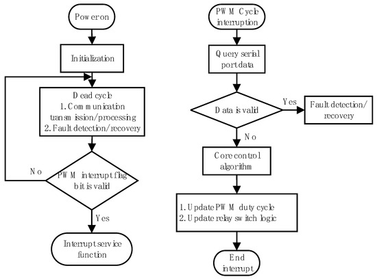
Figure 29.
Main framework flowchart.
5.2. Analysis of Experimental Results
As outlined in the preceding chapters, the experimental platform was constructed using a programmable AC source to emulate the grid and a bidirectional programmable DC source to simulate photovoltaic input for renewable energy integration. The detection algorithm employs the instantaneous reactive power (dq) theory to separate AC and DC components, while the compensation strategy utilizes the pre-sag method. A three-phase three-level neutral-point-clamped inverter was selected as the core of the conversion unit. Experimental validation conducted on this customized Dynamic Voltage Restorer platform confirms the correct operation of all functions, demonstrates the effectiveness of the pre-sag compensation strategy, and verifies the rationality of the modular hardware and control design.
5.2.1. Analysis of Voltage Transient Experimental Results
Using phase A of the dynamic Voltage Restorer as an example, a voltage sag with a depth of 20% and a duration of 0.3 s is applied to the grid voltage. Figure 30 shows the resulting voltage waveform during this single-phase 20% voltage sag.
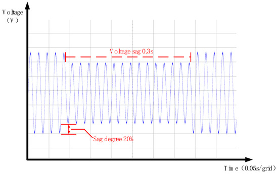
Figure 30.
Single-phase voltage dip of 20%—experimental grid voltage waveforms.
The phase angle at the inception of the voltage sag is captured by the phase-locked loop, ensuring consistent phase alignment between the grid and load voltages. The compensation voltage output by the DVR—which is generated by inverting the DC power to AC using the three-level inverter and then injecting it via the coupling transformer—is shown in the waveform in Figure 31.
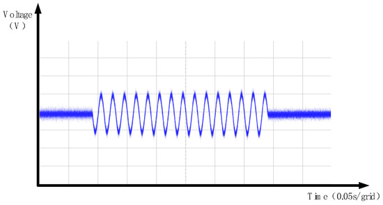
Figure 31.
Single-phase voltage dip of 20%—experimental DVR output voltage waveforms.
Finally, by combining the DVR output compensation voltage with the grid voltage after the sag, the load-side voltage waveform shown in Figure 30 is obtained. Analysis of Figure 31 and Figure 32 indicates that the instantaneous dq detection method employed in the DVR enables a rapid response to grid voltage sags, and the pre-sag compensation strategy effectively restores both the phase and amplitude to the pre-sag condition, thereby ensuring the stability of the load voltage waveform. These results confirm the correct operation of the designed Dynamic Voltage Restorer platform, the efficacy of the pre-sag compensation method, and the rationality of the modular design.
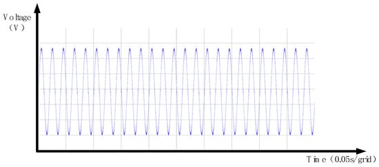
Figure 32.
Single-phase voltage dip of 20%—experimental load-side voltage waveforms.
To evaluate the compensation capability of the DVR under more severe grid voltage sags, additional tests were conducted with sag depths of 50% and 100%, each with a duration of 0.5 s. As shown in Figure 33, a 50% voltage sag is applied. Once the detection unit identifies the sag, the DVR immediately injects the compensating voltage, the waveform of which is shown in Figure 34. After superimposing the DVR output onto the grid voltage, the resulting load voltage waveform is restored to the nominal level, as illustrated in Figure 35.
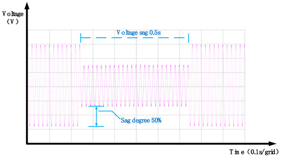
Figure 33.
Single-phase voltage dip of 50%—experimental grid voltage waveforms.
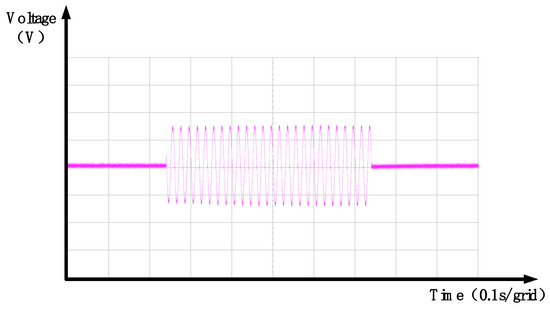
Figure 34.
Single-phase voltage dip of 50%—experimental DVR output voltage waveforms.
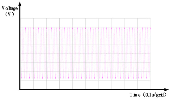
Figure 35.
Single-phase voltage dip of 50%—experimental load-side voltage waveforms.
As shown in Figure 36, a grid voltage sag with a depth of 100% and a duration of 0.5 s is applied. Upon detection of the sag by the monitoring unit, a switching signal is sent to the inverter, triggering the DVR to generate and inject the compensation voltage, the waveform of which is shown in Figure 37. This ensures that the load voltage maintains a standard sinusoidal waveform, as depicted in Figure 38. In summary, at the onset of the voltage sag, the phase-locked loop (PLL) accurately captures the phase angle of the sagged voltage, maintaining phase consistency between the grid and the load voltage. The compensation voltage, produced by the inverter and injected via the coupling transformer, ensures that the load voltage remains a stable sinusoid. Even under severe sag conditions, the DVR system effectively supplies the required compensation, validating the functionality of the proposed Dynamic Voltage Restorer platform and the soundness of its modular design.
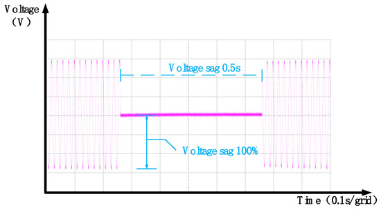
Figure 36.
Single-phase voltage dip of 100%—experimental grid voltage waveforms.
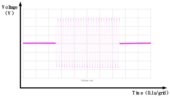
Figure 37.
Single-phase voltage dip of 100%—experimental DVR output voltage waveforms.
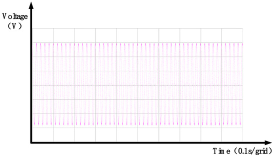
Figure 38.
Single-phase voltage dip of 100%—experimental load-side voltage waveforms.
5.2.2. Analysis of Voltage Surge Experimental Results
Using phase A of the Dynamic Voltage Restorer as an example, a voltage swell with a duration of 0.3 s and a magnitude of 20% is applied to the grid. The resulting grid voltage waveform during this single-phase voltage swell is presented in Figure 39.
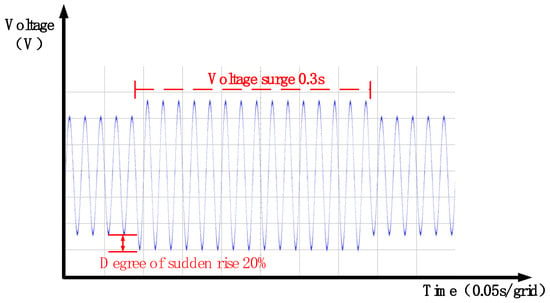
Figure 39.
Waveform of the grid voltage during a single-phase voltage surge.
5.2.3. Analysis of Experimental Results for Voltage Compensation Dynamic Characteristics
The International Electrotechnical Commission (IEC) specifies requirements for the dynamic response time of harmonic suppression and voltage waveform distortion mitigation primarily in the IEC 61000-4-7 standard [30]. According to this standard, under a 20% load step change, the dynamic response time of power quality monitoring devices must be ≤10 ms. Additionally, active power filters (APFs) are required to achieve a response time of less than 10 ms, with the capability to rapidly track changes within 5 ms. Analysis of the experimental voltage sag and swell waveforms demonstrates the system’s compensation performance under various voltage disturbances and harmonic interference. By employing a high-precision dynamic voltage recovery control strategy with harmonic suppression, instantaneous harmonic voltage compensation is achieved. The specific quantitative relationships are presented in Table 3.
5.2.4. Analysis of Power Transfer Experimental Results
Figure 40 shows the power transfer diagram among the grid, the DVR, and the load. Power complementation between the photovoltaic storage system and the grid improves the utilization efficiency of the integrated PV storage system. During the periods of 0–0.09 s and 0.83–1 s, when no grid voltage issues occur, the power required by the load is fully supplied by the grid, and the DVR does not participate in power transfer or compensation. During 0.09–0.3 s and 0.52–0.83 s, when voltage sags occur in the grid, the energy storage unit on the DVR side provides power compensation. Between 0.3 s and 0.52 s, during a grid voltage swell, the excess power is absorbed by the DVR side, thereby maintaining constant power to the load.
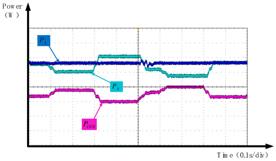
Figure 40.
Power transfer diagram.
6. Conclusions
This study focuses on a photovoltaic (PV) energy storage-based Dynamic Voltage Restorer (DVR), conducting in-depth multi-angle research, from theoretical analysis and simulation to experimental validation. To address the issue of insufficient phase detection accuracy and inability to extract positive-sequence components in traditional phase-locked loops (PLLs) under harmonic distortion scenarios—which leads to difficulties in effectively filtering out high-order harmonic components in sagged voltages—a high-precision harmonic suppression strategy based on the collaborative optimization of a software phase-locked loop (SPLL) and a Butterworth filter is proposed. By performing dq transformation on three-phase voltages, a software phase-locked loop with rapid dynamic response capability is constructed, thereby improving phase detection accuracy and ensuring more precise extraction of positive-sequence components from voltage signals. The compensation strategy of the DVR is analyzed, and considering the integration of the DVR with PV and energy storage, a pre-sag compensation strategy is adopted. The study begins by examining the shortcomings of existing research, pointing out that current studies only achieve a simple integration of renewable energy with DVRs. A power coordination method for PV energy storage-based DVRs is proposed to address power coordination issues among PV systems, the grid, and loads. A physical power platform is built with full digital control to experimentally validate the compensation effectiveness of the DVR, covering scenarios such as voltage sags, swells, and power transfer. Experimental data align with simulation results, and the prototype demonstrates rapid response and accurate compensation in practical operation, confirming the feasibility and effectiveness of the designed topology and control strategy.
In subsequent research, further in-depth study will be conducted on the compensation performance of PV energy storage-based DVRs, while also investigating the control effects under load variations and long-term operation. Considerations will include impacts such as battery aging. Experiments will emphasize dynamic performance analysis and validation during mode transitions.
Author Contributions
Conceptualization, T.Z. and Y.Z.; methodology, Z.W. and Z.Y.; validation, Z.Y. and Z.Z.; formal analysis, T.Z., Y.Z. and Z.W.; investigation, Z.W.; resources, Z.Y.; writing—original draft preparation, Y.Z. and T.Z.; writing—review and editing, T.Z.; supervision, Z.Y.; project administration, Y.Z. All authors have read and agreed to the published version of the manuscript.
Funding
This work was support in part by the National Natural Science Foundation of China (NSFC) under Grant 51877058 and Zhejiang R&D Key Research Plan under grant 2023C03154.
Data Availability Statement
The original contributions presented in this study are included in the article. Further inquiries can be directed to the corresponding author.
Conflicts of Interest
The authors declare no conflicts of interest.
References
- Krishna, D.G.A.; Anbalagan, K.; Prabhakaran, K.K.; Kumar, S. An Efficient Pseudo-Derivative-Feedback-Based Voltage Controller for DVR Under Distorted Grid Conditions. IEEE J. Emerg. Sel. Top. Ind. Electron. 2021, 2, 71–81. [Google Scholar] [CrossRef]
- Sandhya, K.; Laxmi, A.J.; Soni, M.P. Design of PI and Fuzzy Controllers for Dynamic Voltage Restorer (DVR). AASRI Procedia 2012, 2, 149–155. [Google Scholar] [CrossRef]
- Zhang, J.; Huang, Y. Research on Low voltage ride through Control Technology Based on Dynamic Voltage Restorer. In Proceedings of the 2020 IEEE 4th Conference on Energy Internet and Energy System Integration (EI2), Wuhan, China, 30 October–1 November 2020. [Google Scholar]
- IEC 61000-4-30:2021; Electromagnetic Compatibility (EMC)—Part 4-30: Testing and Measurement Techniques—Power Quality Measurement Methods. International Electrotechnical Commission: Geneva, Switzerland, 2021.
- Wang, T.; Lu, L.; Yu, L.; Huang, J.; Wei, Q.; Lu, P. Comprehensive Design and Simulation Study of the Dynamic Voltage Restorer. In Proceedings of the 2022 IEEE International Conference on Artificial Intelligence and Computer Applications (ICAICA), Dalian, China, 24–26 June 2022. [Google Scholar]
- Zhang, H.; Xiao, G.; Lu, Z.; Chai, Y. Reduce Response Time of Single-Phase Dynamic Voltage Restorer (DVR) in a Wide Range of Operating Conditions for Practical Application. IEEE J. Emerg. Sel. Top. Power Electron. 2022, 10, 2101–2113. [Google Scholar] [CrossRef]
- Roldan-Perez, J.; Garcia-Cerrada, A.; Ochoa-Gimenez, M.; Zamora-Macho, J.L. Delayed-Signal-Cancellation-Based Sag Detector for a Dynamic Voltage Restorer in Distorted Grids. IEEE Trans. Sustain. Energy 2019, 10, 2015–2027. [Google Scholar] [CrossRef]
- Li, P.; Xie, L.; Han, J.; Pang, S.; Li, P. New Decentralized Control Scheme for a Dynamic Voltage Restorer Based on the Elliptical Trajectory Compensation. IEEE Trans. Ind. Electron. 2017, 64, 6484–6495. [Google Scholar] [CrossRef]
- Zaheer, A.; Covic, G.A.; Kacprzak, D. A bipolar pad in a 10-kHz 300-W distributed IPT system for AGV applications. IEEE Trans. Ind. Electron. 2014, 61, 3288–3301. [Google Scholar] [CrossRef]
- Rao, S.M.; Satputaley, R.J.; Keshri, R.K.; Buja, G. Performance Evaluation of MLI Based DVR in Grid Fed EV Fast Charging Station. IEEE Trans. Energy Convers. 2024, 39, 49–61. [Google Scholar] [CrossRef]
- Li, P.; Xie, L.; Han, J.; Pang, S.; Li, P. A New Voltage Compensation Philosophy for Dynamic Voltage Restorer to Mitigate Voltage Sags Using Three-Phase Voltage Ellipse Parameters. IEEE Trans. Power Electron. 2018, 33, 1154–1166. [Google Scholar] [CrossRef]
- Sundarabalan, C.; Selvi, K. Compensation of voltage disturbances using PEMFC supported Dynamic Voltage Restorer. Int. J. Electr. Power Energy Syst. 2015, 71, 77–92. [Google Scholar] [CrossRef]
- Remya, V.K.; Parthiban, P.; Ansal, V.; Nandakumar, A. Single-Phase DVR with Semi-Z-Source Inverter for Power Distribution Network. Arab. J. Sci. Eng. 2018, 43, 3135–3149. [Google Scholar] [CrossRef]
- Al-Gahtani, S.F.; Salem, E.Z.M.; Irshad, S.M.; Azazi, H.Z. Improved Instantaneous Reactive Power (PQ) Theory Based Control of DVR for Compensating Extreme Sag and Swell. IEEE Access 2022, 10, 75186–75204. [Google Scholar] [CrossRef]
- Li, Z.; Guo, X.; Wang, Z.; Yang, R.; Zhao, J.; Chen, G. An Optimal Zero-Sequence Voltage Injection Strategy for DVR Under Asymmetric Sag. IEEE J. Emerg. Sel. Top. Power Electron. 2022, 10, 2595–2607. [Google Scholar] [CrossRef]
- Li, S.; Chang, X.; Wang, H.; Liu, N.; Liu, Y.; Yang, Y.; Duan, Q. Dynamic Voltage Restorer Based on Integrated Energy Optimal Compensation. Electronics 2023, 12, 531. [Google Scholar] [CrossRef]
- Ko, J.-H. High-Definition Dynamic Voltage Restorer Systems Using Equivalent Time Sampling Techniques and Circular Structural Memory Filters. Appl. Sci. 2024, 14, 6896. [Google Scholar] [CrossRef]
- Ibrahim, N.F.; Alkuhayli, A.; Beroual, A.; Khaled, U.; Mahmoud, M.M. Enhancing the Functionality of a Grid-Connected Photovoltaic System in a Distant Egyptian Region Using an Optimized Dynamic Voltage Restorer: Application of Artificial Rabbits Optimization. Sensors 2023, 23, 7146. [Google Scholar] [CrossRef] [PubMed]
- Al-Gahtani, S.F.; Barnawi, A.B.; Azazi, H.Z.; Irshad, S.M.; Bhutto, J.K.; Majahar, H.M.; Salem, E.Z. A New Technique Implemented in Synchronous Reference Frame for DVR Control Under Severe Sag and Swell Conditions. IEEE Access 2022, 10, 25565–25579. [Google Scholar] [CrossRef]
- Naidu, T.A.; Arya, S.R.; Maurya, R. Dynamic Voltage Restorer With Quasi-Newton Filter-Based Control Algorithm and Optimized Values of PI Regulator Gains. IEEE J. Emerg. Sel. Top. Power Electron. 2019, 7, 2476–2485. [Google Scholar] [CrossRef]
- Hung, V.T.; Shu, H.; The, N.D. Double-loop control structure using proportional resonant and sequence-decoupled resonant controllers in static coordinates for dynamic voltage restorer. Chin. J. Electr. Eng. 2019, 5, 10–19. [Google Scholar] [CrossRef]
- Babu, V.; Ahmed, K.S.; Shuaib, Y.M.; Manikandan, M. Power Quality Enhancement Using Dynamic Voltage Restorer (DVR)-Based Predictive Space Vector Transformation (PSVT) with Proportional Resonant (PR)-Controller. IEEE Access 2021, 9, 155380–155392. [Google Scholar] [CrossRef]
- Ye, J.; Gooi, H.B.; Wang, B.; Li, Y.; Liu, Y. Elliptical restoration based single-phase dynamic voltage restorer for source power factor correction. Electr. Power Syst. Res. 2018, 166, 199–209. [Google Scholar] [CrossRef]
- Kumar, P.; Arya, S.R.; Mistry, K.D. Momentum Adaption and Metalearning-Based DVR With Optimized Gains of Fractional-Order PID Controller. IEEE Trans. Aerosp. Electron. Syst. 2024, 60, 1309–1318. [Google Scholar] [CrossRef]
- Biricik, S.; Komurcugil, H.; Tuyen, N.D.; Basu, M. Protection of Sensitive Loads Using Sliding Mode Controlled Three-Phase DVR With Adaptive Notch Filter. IEEE Trans. Ind. Electron. 2019, 66, 5465–5475. [Google Scholar] [CrossRef]
- Nalla, L.; Mishra, M.K.; Ghosh, A. Sliding Mode Control of a Four-Leg Dynamic Voltage Restorer in a Natural Reference Frame. IEEE J. Emerg. Sel. Top. Ind. Electron. 2023, 4, 919–927. [Google Scholar] [CrossRef]
- Biricik, S.; Komurcugil, H.; Ahmed, H.; Babaei, E. Super Twisting Sliding-Mode Control of DVR With Frequency-Adaptive Brockett Oscillator. IEEE Trans. Ind. Electron. 2021, 68, 10730–10739. [Google Scholar] [CrossRef]
- Singh, S.P.; Pathak, D.; Kumar, A.; Padmanaban, S. An Optimized Fractional-Order Modified Adaptive Variable Step-Size LMS Control Approach to Enhance DVR Performance. IEEE Trans. Consum. Electron. 2024, 70, 471–483. [Google Scholar] [CrossRef]
- IEEE Standard 519-2014; IEEE Standard for Harmonic Control in Electric Power Systems. IEEE: New York, NY, USA, 2014.
- IEC 61000-4-7; Electromagnetic Compatibility (EMC)—Part 4-7: Testing and Measurement Techniques—General Guide on Harmonics and Interharmonics Measurements and Instrumentation, for Power Supply Systems and Equipment Connected Thereto. IEC: Geneva, Switzerland, 2009.
Disclaimer/Publisher’s Note: The statements, opinions and data contained in all publications are solely those of the individual author(s) and contributor(s) and not of MDPI and/or the editor(s). MDPI and/or the editor(s) disclaim responsibility for any injury to people or property resulting from any ideas, methods, instructions or products referred to in the content. |
© 2025 by the authors. Licensee MDPI, Basel, Switzerland. This article is an open access article distributed under the terms and conditions of the Creative Commons Attribution (CC BY) license (https://creativecommons.org/licenses/by/4.0/).