Abstract
In view of the DC bus voltage fluctuation caused by the short-term periodic power demand of pulsed power loads (PPLs), this paper introduces a power allocation and tracking method for a hybrid energy storage system (HESS) with pulsed loads, aiming to improve the stability of the bus voltage. Firstly, a pulse power allocation and tracking method based on AC and DC components is proposed. Then, by introducing a current estimating method, a reference output current extraction from the AC component is obtained for model predictive control, which is used to control the supercapacitor converter, while the DC power is provided to inform the droop control to drive the battery converter. Finally, a frequency domain model is established to study the suppression effect of the control method on DC bus fluctuations, providing a reliable control scheme for HESS with pulsed power loads.
1. Introduction
In typical shipboard DC microgrids, specific types of loads—such as radar, sonar, and electromagnetic weaponry—periodically draw substantial amounts of energy from the power system [1]. These types of intermittent high-demand loads are collectively referred to as pulsed power loads (PPLs). To maintain stable, efficient, and dependable operation within the DC microgrid, bi-directional DC/DC converters are commonly employed as direct interfaces for supplying high-power PPLs. These converters are responsible for controlling power flow and regulating both voltage and current. However, the presence of PPLs brings operational risks in the shipboard DC microgrid, as the sudden fluctuations in load current create significant challenges for controlling the DC bus voltage and maintaining consistent output voltage levels [2,3,4]. The drop and overshoot of DC bus voltage can cause abnormal operation of propulsion systems, weapon systems, and other sensitive onboard equipment. Therefore, pulse power supplies with key characteristics such as high reliability, electrical isolation, and full controllability are needed to ensure a stable power supply for PPLs in shipboard microgrids. This operational context has highlighted the technical merits of Dual Active Bridge (DAB) DC-DC converters, a topology pioneered by De Doncker’s research team in foundational power electronics studies. Due to its high efficiency, flexibility, high frequency electrical isolation, high voltage lifting capacity, and high conversion efficiency, it has attracted wide attention in shipboard DC microgrids [5,6]. The typical architecture of a shipboard power system consists of power supply device, energy storage system, transformer-based dual active full-bridge DC-DC converters, ordinary load, and pulse power load [7,8].
HESS is frequently employed in shipboard DC microgrids to mitigate fluctuations in the DC bus voltage that result from the short-term, high-power demands of PPLs. Despite their widespread use, many existing studies treat the HESS as a unified system in which the two interface converters operate under full information sharing.
Control strategies for HESS are generally classified into two categories: centralized control and distributed control. In a centralized control architecture, a central controller dispatches commands and receives status feedback from each energy unit, thereby enabling coordinated operation among multiple energy sources. Filters play a significant role in such control frameworks. For example, classical first-order filters are adopted in [9,10] to effectively separate high- and low-frequency power components. In contrast, more advanced second-order filters are utilized in [11] to suppress power fluctuations, thus achieving superior frequency-based power separation. Reference [8] proposes a two-stage low-pass filter control strategy employing variable filter time constants to optimize power distribution between batteries and supercapacitors (SCs). A dynamic power-sharing method based on multiple filters for grid-connected HESS is introduced in [12]. Similarly [13] presents an adaptive energy management approach, in which the filter time constant is dynamically adjusted to improve SC utilization and extend battery lifespan.
Despite enabling centralized coordination, such strategies rely heavily on the central controller, resulting in a single point of failure. This dependency significantly compromises system reliability, particularly as the number of integrated energy sources increases [14]. Furthermore, the computational burden on the controller grows with system complexity, making centralized schemes less practical for large-scale HESS applications.
In contrast, distributed control does not depend on a central controller; instead, it utilizes only local information and avoids communication between control units [15]. This autonomous nature enhances system modularity and supports plug-and-play functionality. Among distributed strategies, droop control is the most representative method. A virtual capacitor-based droop control technique is proposed in [16], enabling frequency-based power distribution and facilitating SC state-of-charge (SOC) recovery in battery–SC systems. Voltage regulation and SOC restoration are further addressed in [17,18] through droop methods incorporating DC bus voltage compensation.
However, the above methods mainly target HESS system with formal loads. HESS supplying for PLLs is still a challenge which has pulse power characteristics, so there are insufficient control strategies. In view of the DC bus voltage fluctuation caused by the short-term periodic power demand of pulsed power loads, this paper introduces a power allocation and tracking method for a hybrid energy storage system (HESS) with pulsed loads, aiming to improve the stability of the bus voltage. The main innovations of the paper are listed as follows:
- (1)
- A dynamic power allocation for hybrid energy storage systems based on the AC-DC decoupling framework are proposed to give an effective reference the controller.
- (2)
- A real-time tracking methodology based on MPC controllers with variable step which can track the AC component of PPLs is proposed, effectively avoiding large-scale periodic fluctuations in the DC bus.
- (3)
- The attenuation performance of the proposed dynamic power allocation strategy on DC bus voltage oscillations is quantitatively evaluated through an impedance-based frequency–domain analytical model.
The rest of this article is organized as follows. In Section 2, AC current estimation of hybrid energy storage system with DAB converter and Pulse power tracking method based on MPC are proposed. In Section 3, Frequency domain analysis of pulse power allocation and tracking methods are presented. In Section 4, case study of hybrid energy storage power distribution is provided to verify the effectiveness of the proposed method. Finally, Section 5 concludes this article.
2. Estimation and Tracking Method of AC Current
2.1. AC Current Estimation of Hybrid Energy Storage System with DAB Converter
2.1.1. Analysis of HESS Power Supply Method with DAB Converter
Existing HESS methods of powering PPLs often underutilize the SC’s capacity. As illustrated in Figure 1, during PPL operation, the battery-side converter output current predominantly carries the AC component, whereas the SC side output current appears only briefly. This indicates that peak power is still largely handled by the battery, despite the fact that high-capacity battery modules are significantly more expensive than their SC counterparts. Furthermore, the droop control behavior inherent in the battery converter can lead to recurring oscillations in the DC bus voltage. Within this research framework, the baseline power allocation approach is designated as the steady state/transient distribution method.
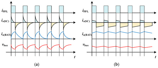
Figure 1.
HESS distribution method (a) Stable/transient distribution (b) DC/AC distribution.
The DC/AC power allocation methodology in pulsed energy systems provides a viable alternative to traditional steady-state/transient partitioning. Figure 1b illustrates how this control scheme directs the SC converter to primarily handle the AC current component. Consequently, the utilization of the SC is significantly improved, fluctuations in the DC bus are effectively suppressed, and the inrush current stress on energy storage cells is notably reduced. Figure 2 depicts the HESS-integrated DC microgrid topology employing DAB converters, containing three primary elements: power generation units, standard loads, and PPLs. To address the power mismatch between generation and load demand, the HESS dynamically balances system energy flow. This allows the architecture to be represented through an equivalent circuit representation dashed boundary in Figure 2, where the HESS functionally replaces the combined load. For control implementation, operational modeling assumes the SC converter behaves as an ideal current source, with intentional integration of output filter inductance to stabilize current dynamics. Simultaneously, an input-side filter inductor is introduced at the battery converter to mitigate current ripple, which helps reduce stress on the battery and extend its operational lifespan.
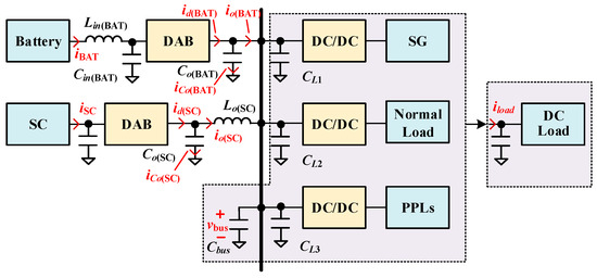
Figure 2.
HESS structure with DAB interface converter.
2.1.2. AC Current Estimation and Discretization
Although the loads are represented as an aggregated equivalent, directly measuring the total load current is often impractical due to the physical dispersion of loads across various locations. To address this, a load current estimating method is introduced to approximate the overall system load current and facilitate the extraction of its AC component. The droop-controlled battery converter’s steady-state dynamics are analytically modeled as:
and represent the battery converter’s output voltage and current, respectively; corresponds to the nominal DC bus voltage, with defining the droop resistance parameter. As illustrated in Figure 2, the total output current of the HESS consistently matches the system’s equivalent load current, which can be mathematically represented as:
, , and correspond to total load current, battery converter output current, and supercapacitor (SC) converter output current, respectively. refers to the secondary-side current of the battery converter, while denotes its average value.
denotes the output capacitor current. When generation-load equilibrium is achieved, the DC bus voltage maintains stability, thereby is zero. The secondary-side current can be formulated as:
Within this analytical framework, is defined as the DC bus voltage, with uppercase variables signifying time-averaged system parameters. Under dynamic load conditions, the capacitor current through the battery converter’s output capacitor is governed by the following relationship:
denotes the battery converter’s output capacitance. Synthesizing Equations (1)–(4), the dynamic load current is analytically expressed as:
Load current load estimate can be expressed as:
where denotes a second-order differentiator with a defined cutoff angular frequency. Equation (6) relies solely on local, real-time measurements of and , while parameters such as , and are assumed to be known a priori. Traditional differentiators tend to amplify high-frequency noise due to their unbounded gain at higher frequencies. To resolve this limitation, we implement a second-order differentiation operator with analytically characterized amplitude-phase frequency response:
At lower angular frequencies, functions as a conventional differentiator. Beyond the cutoff frequency, the system transitions to gain-constrained integrator dynamics, enabling effective high-frequency noise suppression. It should be noted that the second-order differentiator provides a favorable trade-off between high-frequency noise suppression and phase performance. The additional phase lag introduced near timing frequency is limited and does not significantly affect the stability of the control loop. For precision extraction of the load current’s AC component, a first-order Butterworth high-pass filter is cascaded in the control loop.
where denote the high-pass filter’s cutoff angular frequency. Under pulsed load conditions, the operational logic allocates high-frequency current components to the SC unit, while the battery unit absorbs the low-frequency residual. The resultant battery converter current ripple after the initial pulse excitation is analytically modeled as:
where denotes the pulse duration, represents the maximum duty cycle of the PPL, and is the minimum operating frequency of the PPL. In this analysis, is set to 30%, and ≤0.2π is chosen to ensure that the ripple remains below 20% of the pulsed current. Since the HPF blocks the steady-state component, the SC converter’s dynamic current reference is explicitly derived from the attenuated AC residue:
Using bilinear transformation, Equation (10) can be expressed as:
represent the switching/sampling period, with coefficients – analytically defined through the discretized system model as:
The discrete equation is shown in Equation (13), where k is the k-th switching period.
Among them:
2.2. Pulse Power Tracking Method Based on MPC
After the AC current is extracted according to Equation (13), it is used as the reference current for the SC converter. In this high-frequency tracking application, the conventional PI controller cannot meet the tracking speed requirements. Although increasing the open-loop crossover frequency of the PI controller can enhance the tracking speed, it compromises the phase margin, thereby jeopardizing system stability. Therefore, an MPC-based pulse power tracking method for SC converters is studied in this section to meet the requirements of tracking capability and pulse power allocation.
2.2.1. Modeling of SC Converter
Diverging from classical DAB topologies that interface with passive resistive loads, the SC converter architecture integrates an output filter inductance and a regulated DC bus voltage node, fundamentally altering its dynamic power transfer characteristics. The control goal is to track the changing , not to regulate the voltage. Figure 3 depicts the reduced order model equivalent circuit of a DAB converter with additional output inductance.

Figure 3.
Reduced order model circuit of SC converter.
In Figure 3, the equivalent series resistance in the output capacitor branch is considered because the combination of and forms an LC filter. The inherent equivalent series resistance provides critical damping to suppress undamped LC resonance. Furthermore, the auxiliary inductance current exhibits zero-cycle-averaged characteristics, thereby justifying its exclusion from the state-space formulation of the reduced-order system dynamics. After using the reduced order model, the simplified second-order state variable function of the SC converter can be expressed as [18]:
The parameter in this formulation corresponds to the time-averaged secondary-side current of the DAB converter, computable via the steady-state relationship in Equation (11). Implementing a small-signal linearization technique by injecting a perturbation into Equation (15) and neglecting second-order infinitesimals yields the linearized dynamics encapsulated in the state-space matrix representation of Equation (16). Here, L defines the DAB’s power transfer inductance, is the half-period duration of the switching frequency, and n quantifies the secondary-to-primary transformer turns ratio [19].
Following linear system theory, the duty cycle-to-output current transfer function to is analytically expressed as:
2.2.2. SC Converter Pulse Power Tracking Method Based on MPC Control
Employing the forward Euler discretization method on the continuous-time dynamics governed by Equation (15) yields a discrete-time difference equation as:
The output current of the SC converter at k + 2 time can be expressed as:
Since the bus voltage does not change drastically in one sampling cycle, and the is set to 1 in this paper, Equation (19) can be simplified as follows:
where according to the explanatory model in Section 2, can be represented as:
The MPC strategy of the SC converter is designed to track the reference output current with guaranteed dynamic regulation accuracy. The cost function used in the MPC controller is presented in Equation (22):
MPC controller in this chapter is to meet the tracking ability of the system, does not involve multi-objective control, so the weight coefficient is set to 1. Where can be expressed as:
The principle of MPC control is described as follows: during the control interval from k to k + 1, the previous operating point is the center, the discrete control set is obtained, and the current prediction is carried out according to the discrete control set , and the control quantity corresponding to the minimum cost function value is selected as the control quantity of the k + 1 period. Where u is the coefficient determined by the number of predictive elements required. The discrete control set can be expressed as:
In practical applications, in order to reduce the amount of computation, the proposed MPC needs to reduce the evaluated value within each sampling cycle. Therefore, an adaptive step size Δadp is introduced instead of the search step size Δf to speed up the dynamic performance without increasing u. The adaptive step size is defined as shown in (25).
where represents the saturation value, which is a coefficient associated with dynamic performance. Its value is empirically tuned to achieve the desired system response. As for λ, the larger λ means larger Δadp, results in faster tracking, however, it may also increase oscillations around steady state. Therefore, λ is determined based on the required dynamic performance. In practical control, the value of λ is adjusted empirically to caters for the desired performance, involving a trade-off between rise time and settling time.
2.2.3. DC Power Tracking of Battery Converter Based on Droop Control
The control strategy for the battery converter follows a similar approach to other dual-loop controlled DAB converters. The secondary-side current serves as the inner-loop current regulator, with its corresponding closed-loop topology rigorously depicted in Figure 4:

Figure 4.
Sag control scheme of the battery converter.
In the proposed control framework, the inner current loop bandwidth is engineered to exceed the outer voltage loop bandwidth by at least one decade, satisfying the dominant pole separation criterion for unity-gain approximation. Diverging from conventional voltage-droop control-which feeds back the output current -the modified droop law adopts the secondary-side direct-axis current as the feedback variable, eliminating the need for dedicated output current sensors. By synthesizing the voltage loop bandwidth via = 1/(), the closed-loop output impedance is analytically reduced to a first-order LPF structure:
Figure 5 compares the analytical model predictions with SIMPLIS. The SIMPLIS is used popularly in many scenarios to verify the accuracy of small signal model which proves to be an effective tool for frequency domain simulation. The simulated frequency-response data demonstrate close alignment with the analytical Bode plots across the tested frequency range. This consistency validates the accuracy of the transfer function for the SC converter from to and the closed-loop output impedance transfer function of the battery converter; confirming their suitability for controller design
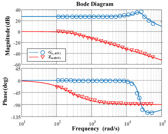
Figure 5.
Modeling verification of DAB converter correlation transfer function.
3. Frequency Domain Analysis of Pulse Power Allocation and Tracking Methods
For DC shipboard microgrids loaded with a large number of PPLs, the minimum pulse time is usually 1 ms. The SC converter’s control architecture requires the output current to reject first-order transient characteristics under static reference current conditions, thereby necessitating dynamic tracking of time-varying reference profiles with bounded tracking error. To rigorously characterize this behavior, this chapter conducts a frequency–domain small-signal impedance spectroscopy analysis of the closed-loop system, anchored in the Nyquist stability criterion. The system parameters utilized in the analysis are detailed in Table 1 and Table 2.

Table 1.
DAB converter system parameters.

Table 2.
DAB converter controller parameters.
3.1. Frequency Domain Analysis of Power Distribution for Hybrid Energy Storage System
Figure 6 depicts the simplified topology of the HESS.

Figure 6.
Simplified HESS model.
can be approximated by in Equation (20), exhibiting the same low-pass characteristics as a voltage source consisting of and . The current transfer ratios and are defined for the relationships between and , and between and , respectively. These transfer functions analytically decompose the load current contributions from the SC and battery converters, respectively. The equivalent parallel output impedance governs the DC bus voltage transient response under load current disturbances. According to Figure 6, the following expression can be derived:
The current transfer ratio and can be expressed as follows:
Among them:
Figure 7 presents the Bode plots of , , and . The frequency spectrum is segmented into three bands, with threshold frequencies f1 and f2 are 0.5 Hz and 900 Hz. In the low-frequency region (below f1), the gain of is lower than that of , indicating that the battery converter primarily supplies the low-frequency load current. Between f1 and f2, || significantly exceeds ||, demonstrating that the SC converter predominantly handles the AC power component in this range. Beyond f2, the magnitude of || declines, as the SC converter’s ability to follow high-frequency AC currents diminishes. Therefore, increasing f2 is necessary to enhance high-frequency tracking performance. Moreover, the DC gain of equals 20lg , confirming that the battery converter’s droop characteristic remains unaffected by the integration of the SC unit.
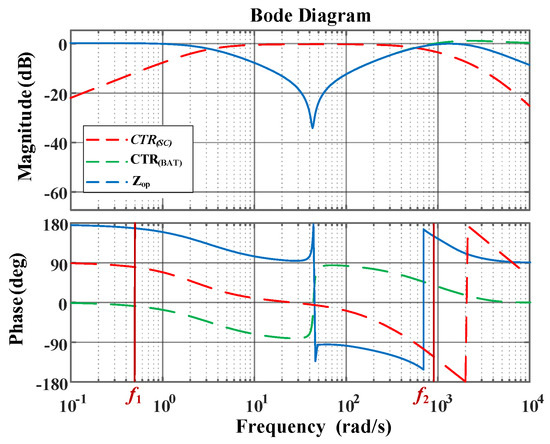
Figure 7.
Bode diagrams of , ||, and .
3.2. Current Tracking Performance Analysis of SC Converter Based on MPC Control
The cost function proposed by Equation (23) reaches the minimum, and the derivative of the cost function with respect to shift ratio D should satisfy Equation (30):
By using the simplified model of single prediction layer and substituting the cost function into Equation (30), we can obtain the expression of optimal transfer comparison:
By introducing small perturbations and ignoring higher-order perturbations, Equation (31) can be expressed as:
According to Equation (32), Equation (33) can be obtained:
According to Equations (17) and (33), the small-signal representation of the SC converter under the MPC control framework is illustrated in Figure 8.
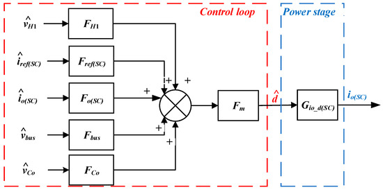
Figure 8.
Small signal model of MPC controlled SC converter.
As depicted in Figure 8, the transfer function , which characterizes the relationship between the SC converter’s output current reference and its actual output current, can be formulated as follows:
Figure 9 gives the verification of the bode diagram for , where the discrete symbols are the frequency sweep results with different D and the theoretical analysis results represented by a straight line. As it can be seen from the figure, the bode diagram of matches well with the results when D = 0.25, D = 0, D = −0.25, which indicates that the tracking performance of SC converters is consistent even in different operating states.
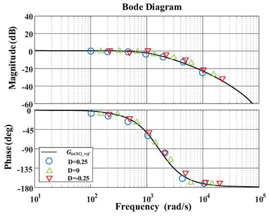
Figure 9.
Verifying the transfer function at different operation points.
3.3. Comparison Between MPC Controller and PI Compensator
The MPC controller exhibits nearly consistent dynamic behavior across various operating points, which benefits SC converter control—particularly under frequent operating point shifts caused by PPLs. In contrast, when employing a PI compensator, the PM must be evaluated for each specific operating condition. Figure 10 illustrates a PI design example at the operating point D = 0, designed to ensure a PM exceeding 60 degrees. The resulting compensator has the form 0.008 + 90/s. To mitigate resonance peaks, the PI compensator reduces the crossover frequency, ultimately achieving a closed-loop bandwidth of approximately 300 Hz.
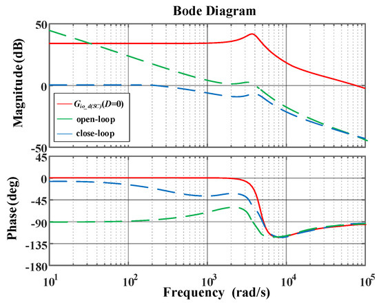
Figure 10.
Bode diagram of , open loop, and closed loop gains based on PI controller.
Figure 11 shows and based on PI controller SC converter, where f1 and f2 are 0.5 Hz and 400 Hz, respectively, it is obvious that compared to the MPC controller, the PI controller exhibits a significantly lower f2, which leads to inferior high-frequency AC current tracking performance.
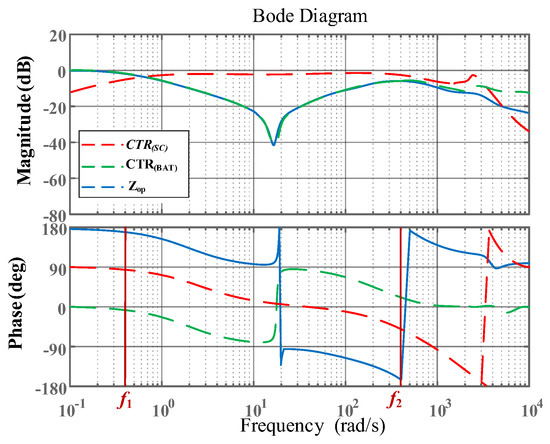
Figure 11.
Bode diagram of , , and under PI control.
4. Case Study of Hybrid Energy Storage Power Distribution
4.1. Analysis of Single SC Converter and Battery Converter
A Hardware-in-the-Loop experiment is carried out and the experimental results are provided to verify the proposed scheme. The specific implementation process is as follows: the tracking performance and busbar voltage fluctuation of the proposed MPC based SC converter are analyzed by time-domain simulation. Figure 12 shows the waveform of SC converter using MPC control method when pulsed power load is running, where PPLs duty cycle is 50% and peak power is about 1 kW.

Figure 12.
Performance analysis of MPC control method when the pulse power duty cycle is 50%.
As can be seen from Figure 12, during intermittent stoppages of the PPLs, the SC converter’s output current stabilizes around −3A. When the PPLs demand a peak current of 10A, the SC converter delivers a peak output of approximately 7A, thereby supplying nearly the entire AC current required by the PPL. In contrast, the battery converter’s output current exhibits smaller fluctuations, indicating that it contributes minimally to the pulse power.
Figure 13 shows the waveform of SC converter using PI controller when pulsed power load is running. It can be obtained from Figure 13a,b. The current tracking performance of SC converters with PI controllers is much slower than that of SC converters with MPC controllers, so the battery converters provide more pulse power, resulting in more dramatic fluctuations in the bus voltage. It should be noted that the proposed MPC has heavier computational burden than traditional PI, while performs better than it. Therefore, it should be weighed between effectiveness and performance according to the specific application scenarios to choose the proper control method.

Figure 13.
Performance analysis of PI control method when the pulse power duty cycle is 50%.
4.2. Analysis of Multiple SC Converters
In the above article, the parallel connection of a single SC converter and a battery converter is analyzed. In practical implementations, a multi-module SC energy storage system topology is shown in Figure 14. To ensure power-sharing equilibrium among paralleled SC units, the MPC strategy is proposed for multi-converter parallel operation.
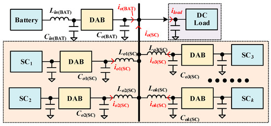
Figure 14.
Connecting multiple SC converters in parallel.
Make the output reference current of each SC converter meet the requirements
The cost function of each SC converter can be expressed as
Figure 15 shows the simulation waveform of output current of each SC converter unit in the process of changing from the traditional voltage control method to the MPC control method.
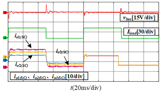
Figure 15.
Power balance based on MPC.
Figure 15 demonstrates that, under traditional voltage control, the transmission power among the SC converters is uneven, with the SC1 converter exhibiting a higher output current compared to the other two converters, which is attributed to its smaller auxiliary inductance. When the MPC power balance scheme is adopted, SC converter can respond to pulse power load in time and realize transmission power balance.
We give a comparison with some references with similar nonlinear controllers which are shown in Table 3. As it can be seen from Table 3, although nonlinear control strategies such as model predictive control and deadbeat control exhibit good control performance, their transient performance which is fast with overshoot will lead to large fluctuation supplying PPLs. For the proposed method, both the transient and steady-state characteristics perform well.

Table 3.
Comparison of the methods.
The research steps can be concluded as Figure 16. This paper introduces a power allocation and tracking method for a HESS with pulsed loads, aiming to improve the stability of the bus voltage. To verification the research, the pulse power tracking based on MPC for SC converter is presented by cost function. Then the frequency–domain analysis for the HESS is carried out based on the small signal model of the system which is compared with PI controller. Finally, the time-domain analysis including HESS system with single SC converter and battery converter as well as HESS system with multiple SC converters is given to indicate the effectiveness of the proposed method on solving the voltage fluctuation.
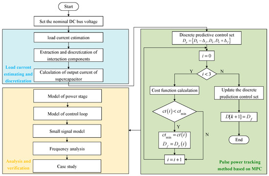
Figure 16.
The step conclusion of research.
Though the proposed method suppresses the effect of the control method on DC bus fluctuations. However, with the increasing number of supercapacitor converters, the sensors for each converter to detect the current or voltage are increasing which leads to increased size and cost. As a result, the proposed method is limited when it extends to the larger system. The next step of research can further reduce the use of sensors for the method.
5. Conclusions
This study develops a dynamic power allocation and real-time tracking methodology for hybrid energy storage systems, based on the AC-DC decoupling framework. First, the DC/AC distribution framework within the HESS DC microgrid is presented, followed by a detailed explanation of the design procedure. Local measurement and AC-DC component extraction are realized by the proposed current estimating method. SC converters based on MPC controllers can track the AC component of PPLs, while battery converters only provide DC power, effectively avoiding large-scale periodic fluctuations in the DC bus. Finally, the attenuation performance of the proposed dynamic power allocation strategy on DC bus voltage oscillations is quantitatively evaluated through an impedance-based frequency–domain analytical model.
Author Contributions
Investigation, L.C.; methodology, L.C.; validation, L.C. and Z.W.; writing—original draft preparation, L.C. and W.Y.; writing—review and editing, Y.Z. and Y.F.; supervision, Y.F. All authors have read and agreed to the published version of the manuscript.
Funding
This work is supported by State Grid Sichuan Electric Power Company Science and Technology Project under Grant 521917230004. (Research on Active Response and Synergistic Comple-mentarity Technology of Multi-type Distributed Generation Microgrid for Sichuan Regional Distribution Network).
Data Availability Statement
The raw data supporting the conclusions of this article will be made available by the authors on request.
Conflicts of Interest
All authors were employed by the company State Grid Sichuan Electric Power Supply Company Meishan Branch. We declare that this research was conducted in the absence of any commercial or financial relationships that could be construed as a potential conflict of interest.
References
- Farhadi, M.; Mohammed, O.A. Performance enhancement of actively controlled hybrid DC microgrid incorporating pulsed load. IEEE Trans. Ind. Appl. 2015, 51, 3570–3578. [Google Scholar] [CrossRef]
- Xue, L.; Shen, Z.; Boroyevich, D.; Mattavelli, P.; Diaz, D. Dual active bridge-based battery charger for plug-in hybrid electric vehicle with charging current containing low frequency ripple. IEEE Trans. Power Electron. 2015, 30, 7299–7307. [Google Scholar] [CrossRef]
- Lu, J.; Bai, K.; Taylor, A.R.; Liu, G.; Brown, A.; Johnson, P.M.; McAmmond, M. A modular-designed three-phase high-efficiency high-power-density EV battery charger using dual/triple-phase-shift control. IEEE Trans. Power Electron. 2018, 33, 8091–8100. [Google Scholar] [CrossRef]
- Liu, C.; Li, B.; Zhang, Y.; Jiang, Q.; Liu, T. The LCC type DC grids forming method and fault ride-through strategy based on fault current limiters. Int. J. Electr. Power Energy Syst. 2025, 170, 110843. [Google Scholar] [CrossRef]
- Hou, N. Research on Optimal Control Method of Full-Bridge Isolated DC-DC Converter. Master’s Thesis, Southwest Jiaotong University, Chengdu, China, 2017. [Google Scholar]
- An, F. Research on Efficiency and Dynamic Performance Optimization of Dual Active Full-Bridge DC-DC Converter. Master’s Thesis, Southwest Jiaotong University, Chengdu, China, 2019. [Google Scholar]
- Jia, C.; Liu, W.; He, H.; Chau, K. Superior energy management for fuel cell vehicles guided by improved DDPG algorithm: Integrating driving intention speed prediction and health-aware control. Appl. Energy 2025, 394, 126195. [Google Scholar] [CrossRef]
- Rasool, S.; Muttaqi, K.M.; Sutanto, D. A multi-filter based dynamic power sharing control for a hybrid energy storage system integrated to a wave energy converter for output power smoothing. IEEE Trans. Sustain. Energy 2022, 13, 1693–1706. [Google Scholar] [CrossRef]
- Forestieri, J.N.; Farasat, M. Integrative sizing/real-time energy management of a hybrid supercapacitor/undersea energy storage system for grid integration of wave energy conversion systems. IEEE J. Emerg. Sel. Top. Power Electron. 2020, 8, 3798–3810. [Google Scholar] [CrossRef]
- Li, X.B.; Liu, J.W. Real-time power distribution method adopting second-order filtering for hybrid energy storage system. Power Syst. Technol. 2019, 43, 1650–1657. [Google Scholar]
- Wu, T.; Yu, W.; Guo, L. A study on use of hybrid energy storage system along with variable filter time constant to smooth dc power fluctuation in microgrid. IEEE Access 2019, 7, 175377–175385. [Google Scholar] [CrossRef]
- Mitra, S.K.; Karanki, S.B. An SOC based adaptive energy management system for hybrid energy storage system integration to dc grid. IEEE Trans. Ind. Appl. 2023, 59, 1152–1161. [Google Scholar] [CrossRef]
- Chen, J.; Song, Q. A decentralized dynamic load power allocation strategy for fuel cell/SC-based APU of large more electric vehicles. IEEE Trans. Ind. Electron. 2019, 66, 865–875. [Google Scholar] [CrossRef]
- Guo, F.; Lian, Z.; Zheng, X.; Deng, C.; Wen, C.; He, J. Decentralized cluster-based distributed secondary control of large-scale DC microgrid cluster system. IEEE Trans. Sustain. Energy 2024, 15, 1652–1662. [Google Scholar] [CrossRef]
- Xu, Q.; Hu, X.; Wang, P.; Xiao, J.; Tu, P.; Wen, C.; Lee, M.Y. A decentralized dynamic power sharing strategy for hybrid energy storage system in autonomous dc microgrid. IEEE Trans. Ind. Electron. 2017, 64, 5930–5941. [Google Scholar] [CrossRef]
- Xu, Q.; Xiao, J.; Hu, X.; Wang, P.; Lee, M.Y. A decentralized power management strategy for hybrid energy storage system with autonomous bus voltage restoration and state-of-charge recovery. IEEE Trans. Ind. Electron. 2017, 64, 7098–7108. [Google Scholar] [CrossRef]
- Xu, Q.; Xiao, J.; Wang, P.; Pan, X.; Wen, C. A decentralized control strategy for autonomous transient power sharing and state-of-charge recovery in hybrid energy storage systems. IEEE Trans. Sustain. Energy 2017, 8, 1443–1452. [Google Scholar] [CrossRef]
- Shao, S.; Chen, L.; Shan, Z.; Gao, F.; Chen, H.; Sha, D.; Dragičević, T. Modeling and advanced control of dual active bridge DC-DC converters: A. review. IEEE Trans. Power Electron. 2022, 37, 1524–1547. [Google Scholar] [CrossRef]
- Yue, X.; Wang, X.; Blaabjerg, F. Review of small-signal modeling methods including frequency-coupling dynamics of power converters. IEEE Trans. Power Electron. 2019, 34, 3313–3328. [Google Scholar] [CrossRef]
- Liu, X.; Suo, Y.; Zhang, Z.; Song, X.; Zhou, J. A new model predictive current control strategy for hybrid energy storage system considering the SOC of the supercapacitor. IEEE J. Emerg. Sel. Top. Power Electron. 2023, 11, 325–338. [Google Scholar] [CrossRef]
- Zhang, X.; Wang, B.; Gamage, D.; Ukil, A. Model predictive and iterative learning control based hybrid control method for hybrid energy storage system. IEEE Trans. Sustain. Energy 2021, 12, 2146–2158. [Google Scholar] [CrossRef]
- Wei, S.; Zhao, Z.; Li, K.; Yuan, L.; Wen, W. Deadbeat current controller for bidirectional dual-active-bridge converter using an enhanced SPS modulation method. IEEE Trans. Power Electron. 2021, 36, 1274–1279. [Google Scholar] [CrossRef]
- Duong, T.-Q.; Choi, S.-J. Deadbeat control with bivariate online parameter identification for SPS-modulated DAB converters. IEEE Access 2022, 10, 54079–54090. [Google Scholar] [CrossRef]
Disclaimer/Publisher’s Note: The statements, opinions and data contained in all publications are solely those of the individual author(s) and contributor(s) and not of MDPI and/or the editor(s). MDPI and/or the editor(s) disclaim responsibility for any injury to people or property resulting from any ideas, methods, instructions or products referred to in the content. |
© 2025 by the authors. Licensee MDPI, Basel, Switzerland. This article is an open access article distributed under the terms and conditions of the Creative Commons Attribution (CC BY) license (https://creativecommons.org/licenses/by/4.0/).