Article

A Flexible and Compact UWB MIMO Antenna with Dual-Band-Notched Double U-Shaped Slot on Mylar® Polyester Film

by
Vanvisa Chutchavong
1,
Wanchalerm Chanwattanapong
1,
Norakamon Wongsin
2,*,
Paitoon Rakluea
2,
Maleeya Tangjitjetsada
3,*,
Chawalit Rakluea
2,
Chatree Mahatthanajatuphat
4 and
Prayoot Akkaraekthalin
4
1
School of Engineering, King Mongkut’s Institute of Technology Ladkrabang, Bangkok 10520, Thailand
2
Department of Electronics and Telecommunication Engineering, Faculty of Engineering, Rajamangala University of Technology Thanyaburi, Pathum Thani 12110, Thailand
3
Department of Electronics and Telecommunication Engineering, Faculty of Engineering and Architecture, Rajamangala University of Technology Suvarnabhumi, Nonthaburi 11000, Thailand
4
Department of Electrical and Computer Engineering, Faculty of Engineering, King Mongkut’s Institute of Technology North Bangkok, Bangkok 10800, Thailand
*
Authors to whom correspondence should be addressed.
Electronics 2025, 14(17), 3363; https://doi.org/10.3390/electronics14173363
Submission received: 30 July 2025 / Revised: 17 August 2025 / Accepted: 19 August 2025 / Published: 24 August 2025
(This article belongs to the Collection MIMO Antennas)

Abstract

Ultra-wideband (UWB) technology is a crucial facilitator for high-data-rate wireless communication due to its extensive frequency spectrum and low power consumption. Simultaneously, multiple-input multiple-output (MIMO) systems have garnered considerable attention owing to their capability to enhance channel capacity and link dependability. This article discusses the development of small, high-performance MIMO UWB antennas with mutual suppression capabilities to fully use the benefits of both technologies. Additionally, the suggested antenna features a straightforward design and dual-band-notched characteristics. The antenna structure includes two radiating elements measuring 85 × 45 mm2. These elements use a rectangular patch provided by a coplanar waveguide (CPW). Double U-shaped slots are incorporated into the rectangular patch to introduce dual-band-notched properties, which help mitigate interference from WiMAX and WLAN communication systems. The antenna is fabricated on a Mylar® polyester film substrate of 0.3 mm in thickness, with a dielectric constant of 3.2. According to the measurement results, the suggested antenna functions efficiently across the frequency spectrum of 2.29 to 20 GHz, with excellent impedance matching throughout the bandwidth. Furthermore, it provides dual-band-notched coverage at 3.08–3.8 GHz for WiMAX and 4.98–5.89 GHz for WLAN. The antenna exhibits impressive performance, including favorable radiation attributes, consistent gain, and little mutual coupling (less than −20 dB). Additionally, the envelope correlation coefficient (ECC) is extremely low (ECC < 0.01) across the working bandwidth, which indicates excellent UWB MIMO performance. This paper offers an appropriate design methodology for future flexible and compact UWB MIMO systems that can serve as interference-resilient antennas for next-generation wireless applications.

1. Introduction

Wireless communication systems have become much more important recently, with several applications necessitating very high-speed data transfer. The Federal Communication Commission (FCC) has permitted the use of unlicensed bands from 3.1 to 10.6 GHz for commercial ultra-wideband (UWB) communication [1,2,3,4,5,6], resulting in significant interest in UWB technology due to its benefits such as high accuracy, elevated data rates over short distances, and minimal power consumption. However, it faces some defects in reliability and a fading signal due to multipath interference. MIMO technology is commonly used to reduce multipath fading and improve data transmission quality [7,8,9,10,11,12]. Therefore, MIMO technology has been combined with a UWB antenna. The small size and low mutual coupling of a UWB MIMO antenna should be considered in its design. Numerous methods have been suggested for UWB MIMO antennas to reduce mutual coupling [13,14,15,16]. Parasitic fragment-type elements between the MIMO antenna elements that produce good isolation were proposed in [13]. This provides design liberty; nevertheless, the optimization procedure is complex and constrained to a restricted frequency range of 2.45 GHz. In [14], researchers described embedding a three-level stepped slot on the central ground of a tiny tapered slot MIMO antenna to enhance isolation. Although the design on FR4 is compact and structurally simple in [14], its efficiency may be compromised due to the properties of the FR4 material. The authors of [15] used the CSRR structure to boost the isolation of the UWB diversity antenna. The applied CSRR structure and inverted-L stubs effectively minimize size and enhance isolation; nevertheless, the complexity of the structure may adversely impact the radiation pattern. The mutual coupling of the MIMO antenna was decreased, as described in [16], by placing an F-shaped stub on the ground plane. The F-shaped stub used on a common ground offers excellent isolation (S21 < −20 dB); yet, it remains comparatively big relative to other designs and is unsuitable for flexible applications.
In addition, the frequency range of UWB systems produces interference with WiMAX at 3.3–3.7 GHz and with WLAN networks between 5.15 and 5.825 GHz. To eliminate interference, a superior antenna for UWB MIMO systems must attenuate frequencies in other application bands while preserving the benefits of the UWB MIMO antenna. Numerous studies on UWB MIMO antennas have utilized a variety of techniques to attempt to develop UWB MIMO antennas with band-notched features [17,18,19,20,21,22,23,24,25]. A small UWB MIMO antenna with a T-shaped ground stub inserted to diminish mutual coupling and parasitic metal strips to notch the WLAN band was presented [17]. The placement of a T-shaped stub beside a parasitic band facilitates a compact configuration and accurate filtration of WLAN signals inside the 5.15–5.85 GHz spectrum, providing a bandwidth coverage of 3–10.6 GHz. However, the structure continues to depend on via holes, which might be intricate to produce. In [18], the authors describe a small band-notched stepped slot UWB MIMO antenna via differentially U-shaped microstrip feed to a half-wavelength resonant stub. Adjusting the stub length to regulate the notch frequency facilitates versatile tuning, while the incorporation of several slots ensures superior isolation. Nonetheless, the antenna’s total dimensions remain somewhat substantial. In [19], a quad-element UWB MIMO antenna etched with four crescent ring-shaped resonant slots on the radiator for notch frequency and reducing mutual coupling based on EBG structure was proposed. The application of a modified EBG structure, including a crescent-shaped resonant slot, enhances isolation and produces a pronounced notch, while preserving high gain and efficiency, making it appropriate for portable devices. Nonetheless, the structure remains intricate owing to the utilization of many vias, rendering it challenging to fabricate, particularly on a small scale. In [20], the authors describe inserting U-shaped and L-shaped slots into the UWB MIMO antenna to notch the WiMAX spectrum. This structure attains significant isolation (−30 dB) and effectively filters the WiMAX spectrum by meticulous slot design. However, a comprehensive examination of its impact on the radiation pattern, which is essential for MIMO systems that need superior link quality, is lacking. In [21], the authors proposed a tapered fed compact UWB diversity antenna using L-shape slit notch dual frequency. This antenna attains dual-band notch and mutual coupling below −22 dB within a compact dimension (18 × 34 mm2), making it appropriate for portable electronics, but the radiation patterns are distorted owing to the antenna’s asymmetry. Loading a trident-shaped strip for a dual-band notch of a UWB MIMO antenna for portable applications in devices was studied [22]. This structure is effective across the full UWB spectrum (3.1–11.8 GHz) owing to the integration of multiple notch mechanisms and isolation in both low and high bands, excluding the specific notch band. However, this increases design complexity, and employing multiple fixed notch structures may reduce flexibility when the interferer band varies. The twin-band-notched UWB MIMO antenna design for surface penetrating applications in [23] rejected two bands by incorporating two symmetrical strips and three interconnected circles of equal radius inside the radiator. Although the antenna was created for surface-penetrating applications with an extensive bandwidth (1.57–12.4 GHz) and tested on actual materials, it possesses a considerable size (56 × 32.47 mm2) and utilizes FR4 material, potentially constraining gain and efficiency in high-sensitivity applications or portable devices with spatial limitations. In [24], a UWB MIMO antenna was designed for dual frequencies by using open-ended quarter-wavelength slots on the radiator and positioning an I-shaped stub on the ground plane to mitigate mutual coupling. This antenna is designed to filter three frequency bands (WiMAX, WLAN, X-band) using quarter-wavelength slots and an I-shaped stub to minimize coupling. Nonetheless, the isolation and ECC are mild (−15 dB, 0.2), perhaps inadequate for high-density MIMO systems. In [25], the authors investigated a small four-port UWB MIMO antenna that uses two shared radiators for a dual-band notch and the meandering line stub to achieve minimal mutual coupling. The integration of a combined radiator and a meandering stub enhances the efficiency of this four-port configuration for bandwidth and isolation (≤−22 dB). Nonetheless, it covers a substantial area (48 × 48 mm2) and has not been evaluated in practical situations, including multidirectional interference or cross-polarization. Each study has distinct benefits; yet, limits regarding size, complexity, and practicality need additional consideration.
Despite ongoing advancements in UWB MIMO antennas regarding notch filtering and mutual coupling suppression, significant deficiencies remain, including structural complexity, flexibility in notch frequency, substantial physical dimensions, and insufficient critical evaluation and testing of MIMO systems in practical environments.
In addition to advancements in UWB MIMO development, recent research has shifted towards conformal antenna technologies that incorporate radiating elements into curved or non-planar structures, preserving aerodynamic and structural integrity. The concept has been expanded to include conformal reflectarrays, transmitarrays, and metasurfaces, providing lightweight, low-profile, and highly directed radiation systems. In [26], it is proposed that the optically transparent conformal reflectarrays utilizing indium tin oxide (ITO) rings and patches exhibit extensive phase coverage, minimal return loss, and improved multi-angle scattering in the X-band, rendering them appealing for stealth and target echo manipulation. Moreover, conformal transmitarrays demonstrate that effective phase control and beam steering can be accomplished on curved surfaces [27], while conformal metasurface arrays utilizing waveguide feeding and semi-analytical dipolar modeling offer systematic frameworks for radiation synthesis with diminished feed complexity [28]. These improvements collectively broaden the potential applications of antennas in communications, radar, stealth technology, and electromagnetic compatibility, hence inspiring the creation of next-generation compact and multifunctional UWB MIMO antennas.
The study proposes and examines an antenna with dual-band-notched features for WLAN and WiMAX communication networks. It is created with a simple construction, a flexible framework, and minimal physical dimensions. This flexibility and robustness are achieved by the utilization of Mylar® polyester film, which provides advantages such as strength, durability, lightweight characteristics, flexibility, and exceptional resistance to moisture, chemicals, and extreme temperatures. The antenna has two rectangular channels and a double-quarter-circular ground plane, supplied by a coplanar waveguide, to provide optimal impedance matching on the UWB frequency spectrum and robust MIMO performance. Two U-shaped slots are included in the radiator to provide dual-band-notched features, with one inverted U-shaped slot designated for notched frequency response within the 3.3–3.7 GHz range (Wi-MAX band) and another allocated for notched frequency response within the 5.1–5.8 GHz range (WLAN band). The CST microwave simulation program was employed to execute and enhance the planned antenna. The simulation and measurement findings are ultimately analyzed.

2. Antenna Design

This section delineates the structure of a dual-band-notched UWB antenna and a UWB-MIMO antenna.

2.1. Antenna Configuration

An antenna will be created for the UWB spectrum, with a double U-shaped configuration for frequency attenuation in the WiMAX and WLAN bands. An identical-shaped antenna will be positioned next to form the UBW MIMO antenna.
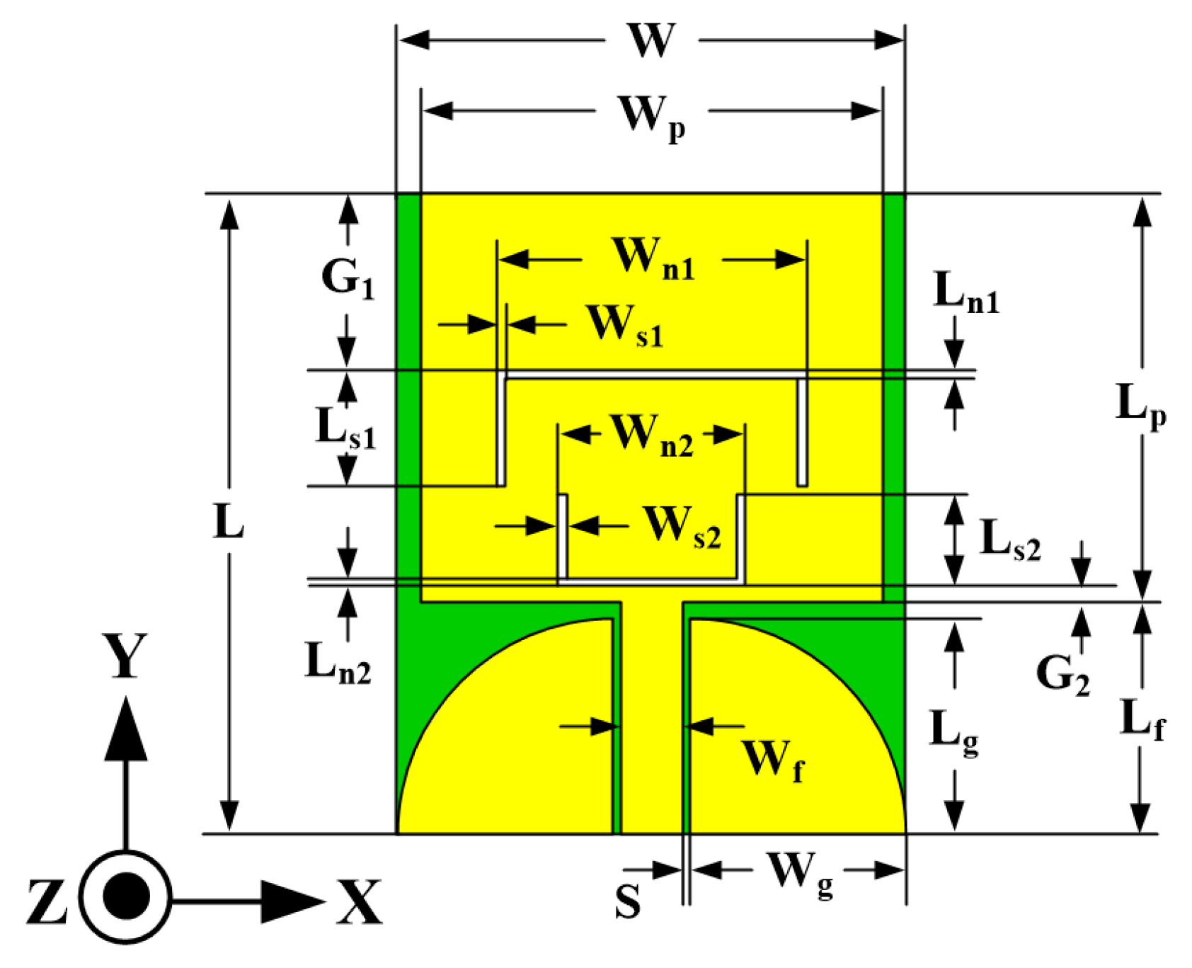
Initially, the UWB antenna with dual-band notches was designed. It was printed on Mylar® polyester film with the dielectric constant (εr) = 3.2, height (h) = 0.3 mm, thickness (t) = 0.1 mm, and tanδ = 0.009. The dimension of the antenna, namely its width (W) and length (L), were determined with CST microwave simulation software 2025, which helped to determine the width (Wf) of the coplanar waveguide (CPW) at impedance (Zc) 50 Ω.
The layout of the UWB antenna with dual-band notching is depicted in Figure 1. The UWB antenna structure contained a rectangular patch using double-quarter-circular ground planes to provide impedance matching, as well as a 50-ohm coplanar waveguide (CPW) for feeding. The rectangular patch was chosen as the primary radiator due to its broadband impedance-matching capability. In addition, the initial electrical length of the radiating patch was determined to be λ0/4 at 3 GHz. Next, the structure for producing band-notched characteristics was introduced. To obtain the first notch frequency in the range of 3.3 to 3.7 GHz, an inverted U-shaped slot with an electrical length of λ0/2 was placed above the UWB antenna, and a U-shaped slot with an electrical length of λ0/2 was placed below an inverted U-shaped slot to realize the second notch frequency in the range of 5.1 to 5.8 GHz. The notched frequencies were regulated by modifying the length of the U legs, which were the Ls1 and Ls2 parameters for notching the WiMAX and WLAN frequencies, respectively. Subsequently, a simulation of the designed antenna using the CST software will be conducted to ascertain the dimensions of the parameters that produced the most optimal outcomes. Table 1 presents the initial sizes of the dual-band-notched UWB antenna.
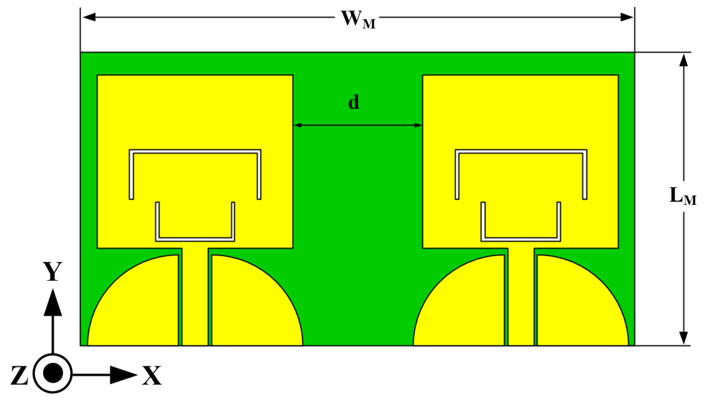
The MIMO capability of the UWB antenna will be established by positioning identical antennas, which are similar in form to those previously fabricated, near one another. Figure 2 illustrates the geometry of the suggested MIMO antenna. A distance (d) of λ0/2 between the antenna elements was used to examine mutual coupling. Table 2 shows the initial dimensions for the UWB MIMO antenna with dual-band notches. The attributes of the MIMO antenna will be assessed using CST software. However, the simulated results will be discussed in the next section.

2.2. Notched Analysis

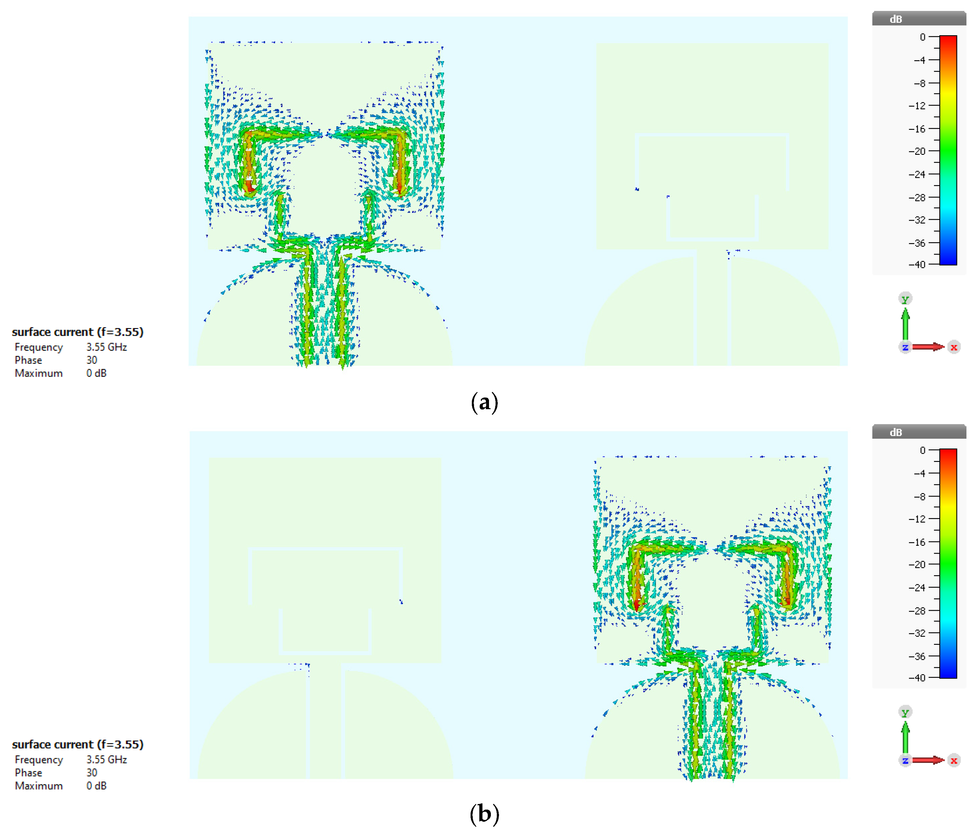
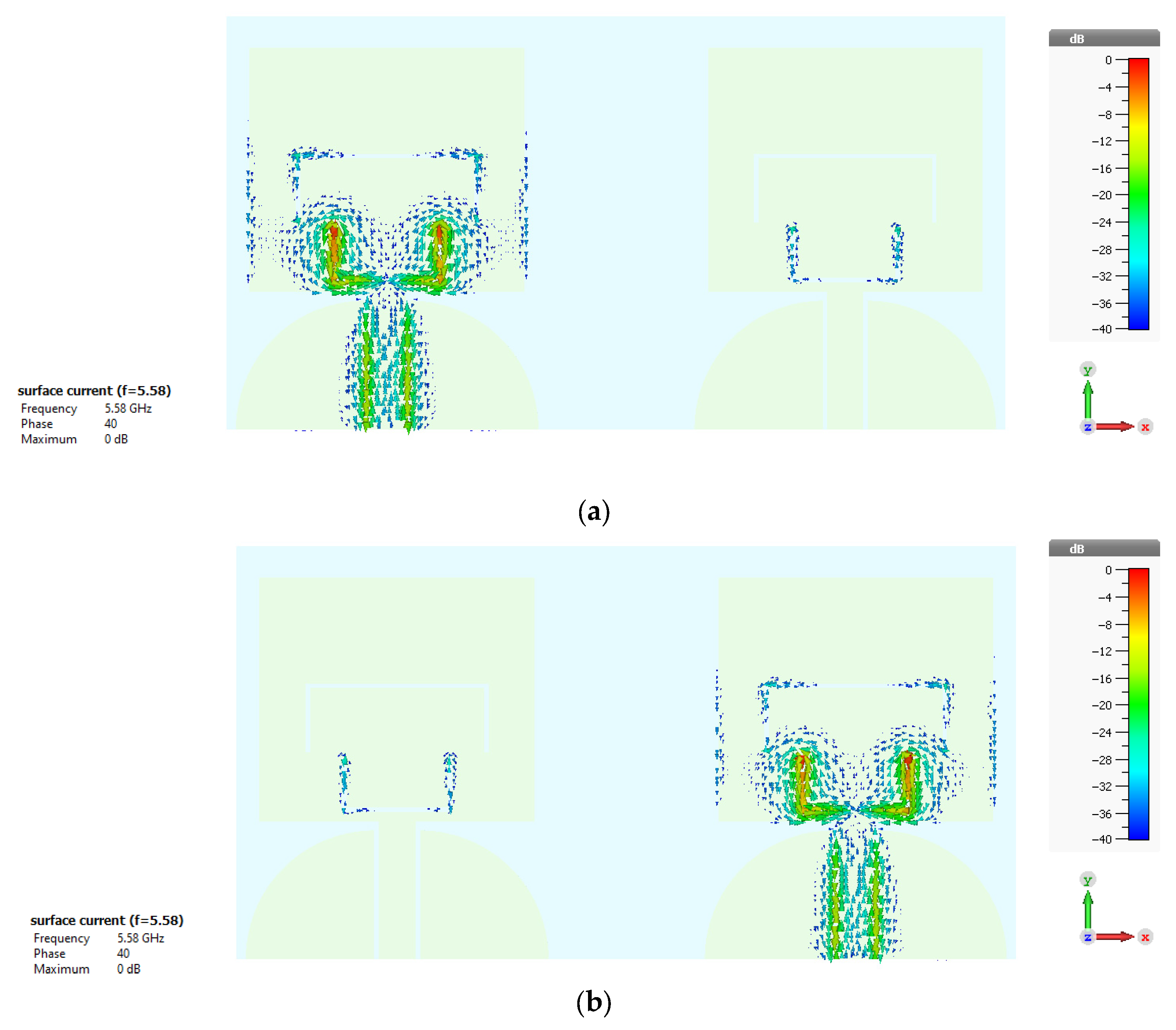
This section presents the assessment of the performance of the suggested antenna at notched frequencies via analysis of the surface current dispersion. Figure 3 depicts the current dispersion on the presented antenna at a notch frequency of 3.55 GHz when activated by ports 1 and 2 separately. According to Figure 3a, the strong surface current was mainly confined to the inverted U-shaped slot on the radiator of the left-side antenna when exciting at port 1. When excited at port 2, the majority of the surface current distribution was concentrated on the inverted U-shaped slot on the radiator of the right-side antenna, as illustrated in Figure 3b. Figure 4 depicts the current dispersion on the proposed antenna at a notch frequency of 5.58 GHz when activated by ports 1 and 2, respectively. The major surface current distribution was concentrated around the U-shaped slot on the radiator of the antenna side, with the excitation ports 1 and 2 as depicted in Figure 4a and Figure 4b, respectively. Consequently, the antenna could not propagate the electromagnetic waves at 3.55 GHz and 5.58 GHz, resulting in interference destruction and insensitivity at notch frequencies.

3. Simulation Results

The antenna design on Mylar® polyester film had a dielectric constant εr = 3.2, a thickness h = 0.3 mm, and a size of 85 × 45 mm2. The antenna was simulated using CST microwave software. In this section, various parametric analyses of the suggested antenna, including the S-parameters, radiation patterns, peak gain, and ECC, are shown and discussed.

3.1. S-Parameters of the Simulation

In this section, we study the simulation results of the characteristics of S-parameters, including the reflection coefficient (S11 and S22 parameters) and the transmission coefficient (S21 parameter) of the proposed antenna.
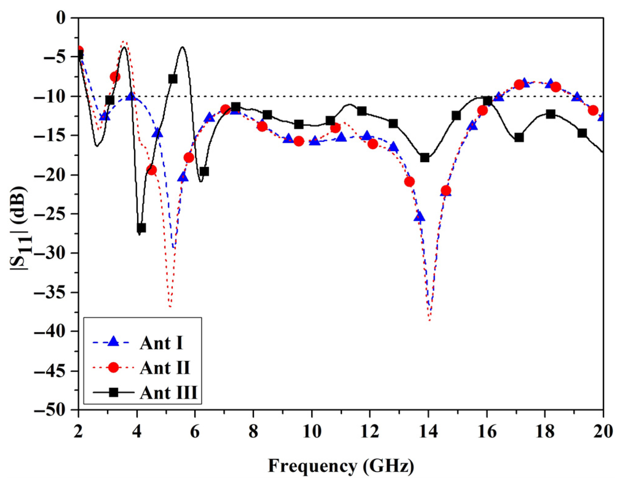
Figure 5 demonstrates the development of the designed antenna from Antenna I to Antenna III. Antenna I is a UWB, Antenna II is a UWB with a single-band notch, and Antenna III is a UWB with dual-band notches. Figure 6 depicts the S11 parameters of Antennas I, II, and III. For Antenna I, the wideband impedance matching was responsible for −10 dB encompassing the entire UWB spectrum from 3.1 to 10.6 GHz (2.28 to 20 GHz). The impedance bandwidth of Antenna II was lower than −10 dB over the entire UWB band, except for the frequency range between 3.3 and 3.7 GHz (WiMAX band). The band was rejected by inserting an inverted U-shaped slot on the radiator of Antenna II. In Antenna III, inserting a U-shaped slot below the inverted U-shaped slot on the radiator rejected the impedance bandwidth at the dual-frequency range of 3.3–3.7 (3.12–3.85) GHz and 5.1–5.8 (5.02–5.84) GHz (WLAN band), while the remaining UWB band had a lower -10 dB impedance bandwidth. This indicates that the designed antenna can reject narrowband interference while maintaining acceptable matching impedance characteristics throughout the UWB band.
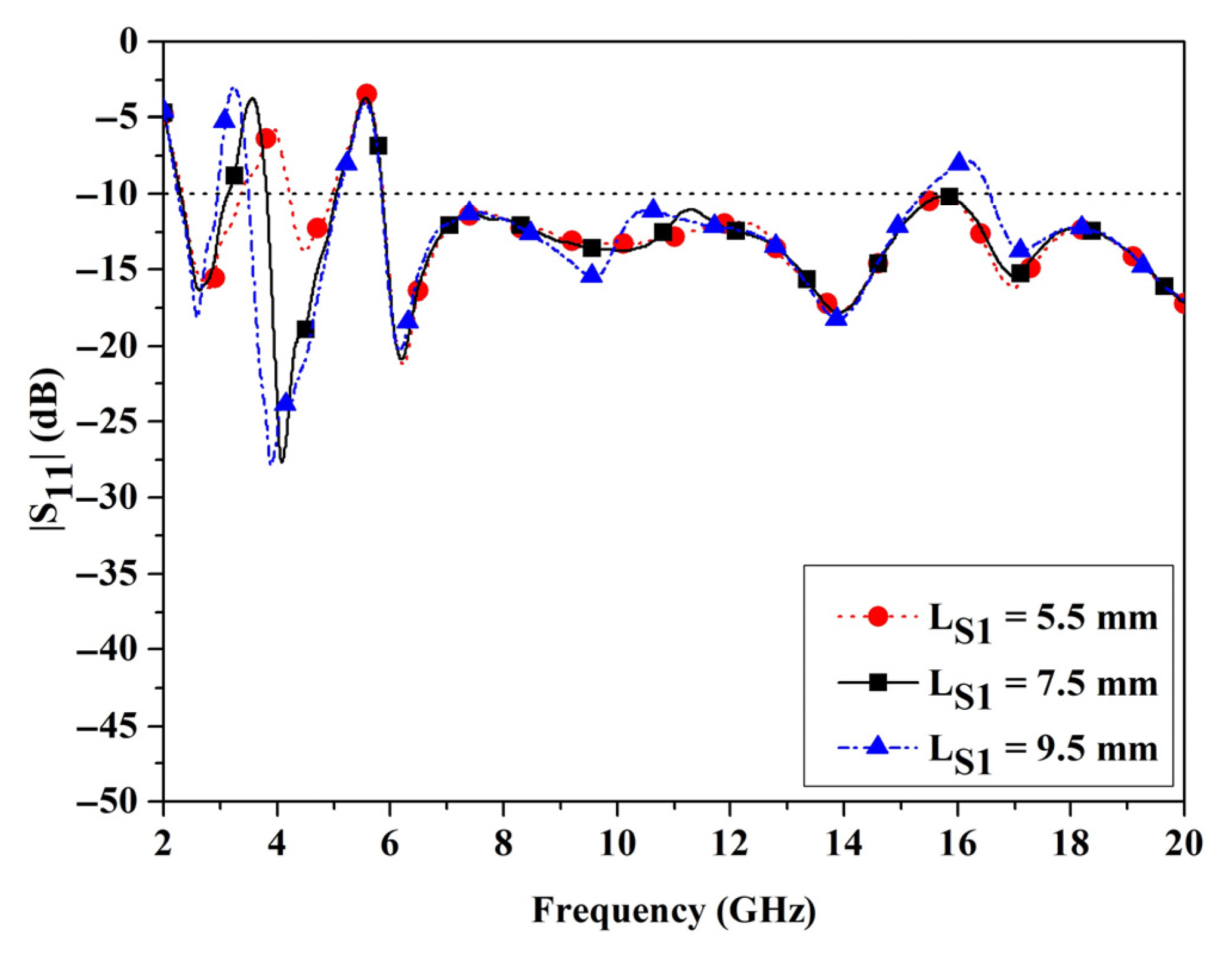
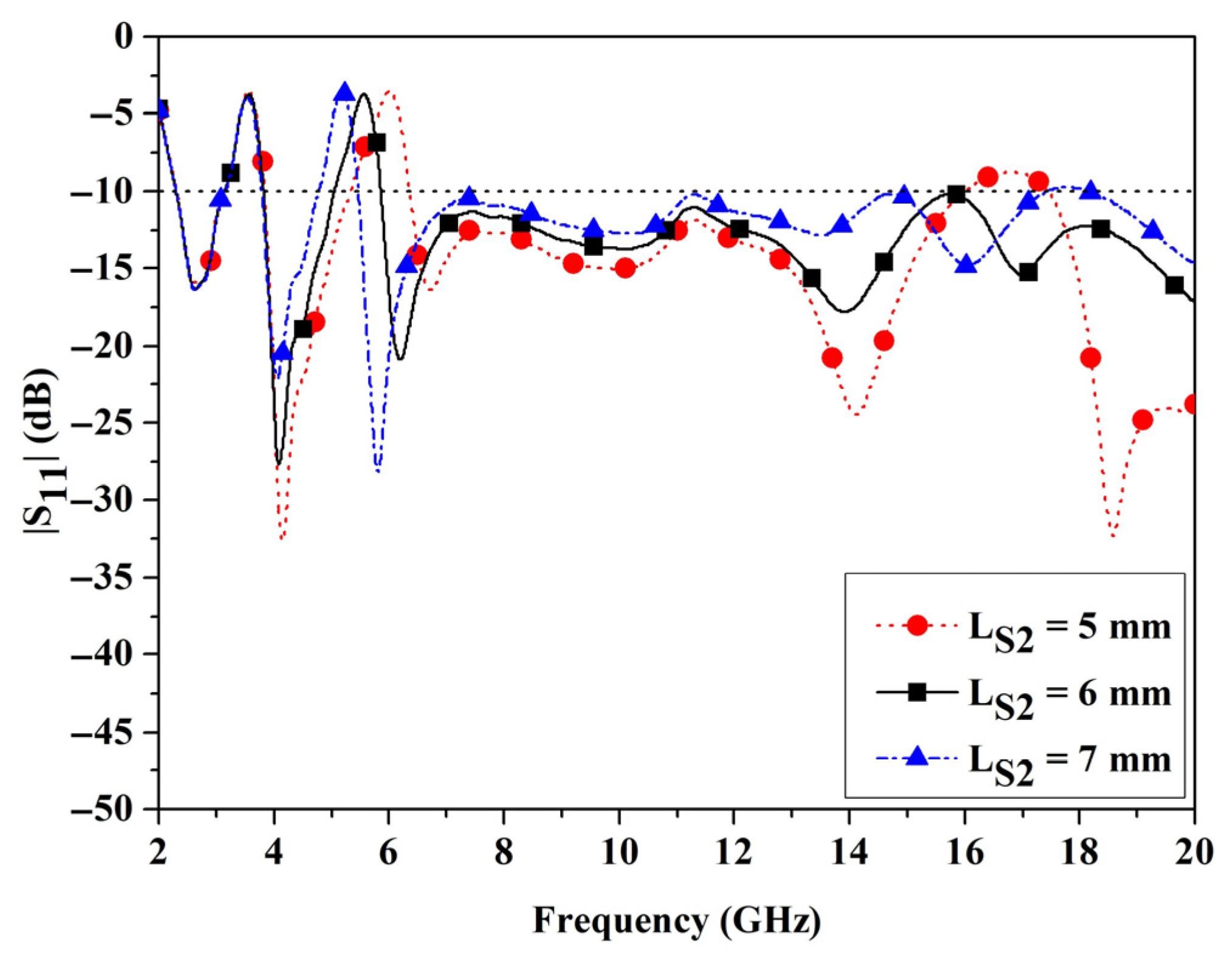
Additionally, the antenna elements influencing the notch frequencies and MIMO features were examined. The antenna components influencing the notch frequency in the WiMAX band included Ls1 of the inverted U-shaped slot, whereas element Ls2 of the U-shaped slot was used to attenuate the WLAN band frequency. Figure 7 illustrates the S11 findings obtained by modifying Ls1 to provide a band-notched response within the spectrum of 3.3–3.7 GHz. As Ls1 increases from 5.5 mm to 9.5 mm, the modified findings of the element revealed that, as the size climbed, the first band-notched response shifted to lower frequencies. Figure 8 depicts the S11 outcomes of modifying Ls2 to achieve a band rejection at the notched frequencies of 5.1 and 5.8 GHz. As Ls2 is incrementally increased from 5 mm to 7 mm, the second band-notched response is shown to shift to lower frequencies. The outcomes of modifying both components are shown in Figure 7 and Figure 8. The simulation findings indicate that the modification of the notch features only influenced the frequency band under investigation, while the other intended working band retained its original properties. Moreover, modifying the notch components of one band did not influence the notch frequencies of the other bands.
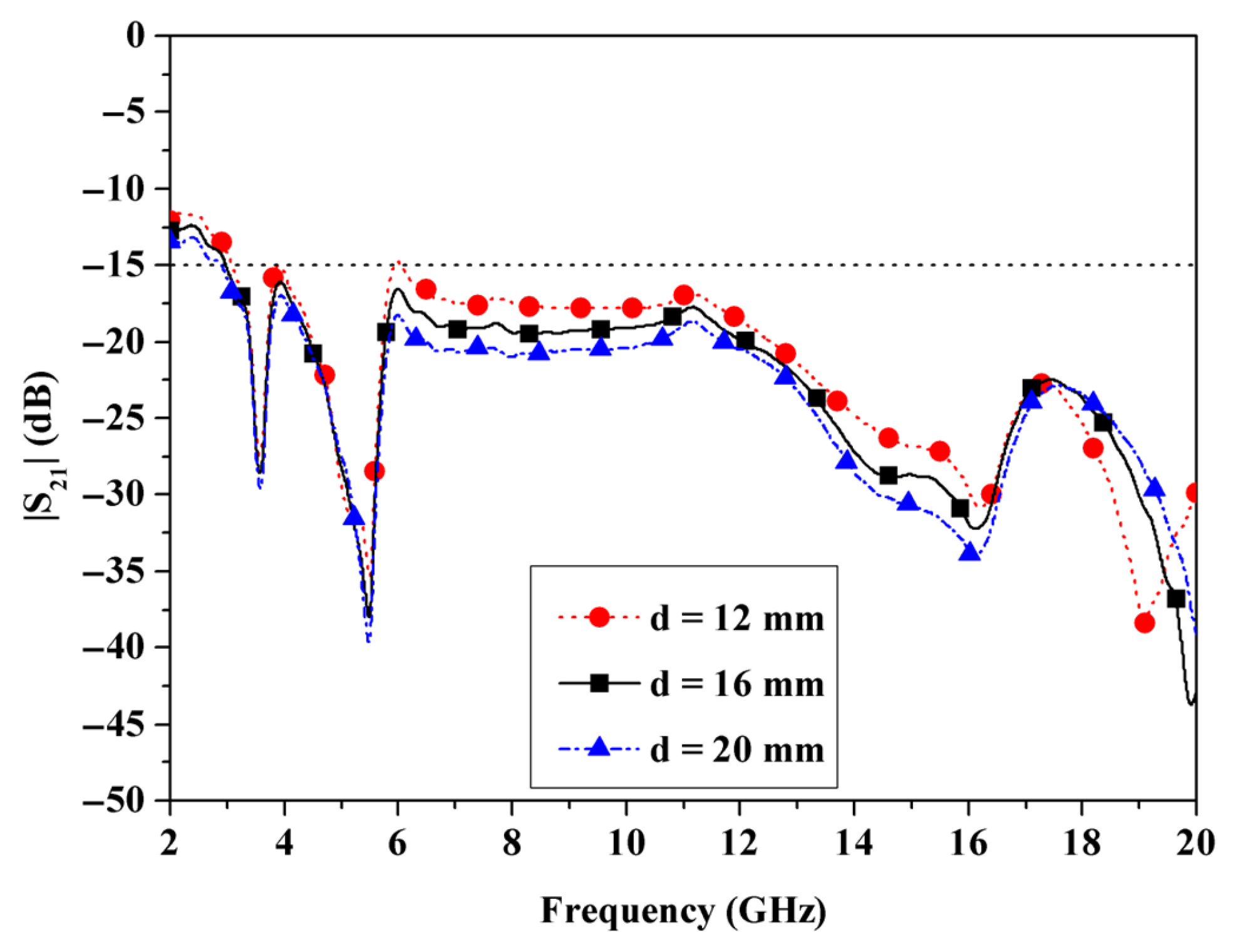
Finally, the MIMO characteristics are examined by altering the distance (d). Figure 9 illustrates the S21 parameters for adjusting the distance (d) between the two adjacent antennas as shown in Figure 2. The results of increasing the distance (d) from 16 mm to 20 mm demonstrate that as the distance increased, the transmission coefficient level decreased. The optimal distance d was 20 mm, which provided a mutual coupling of less than −14 dB.
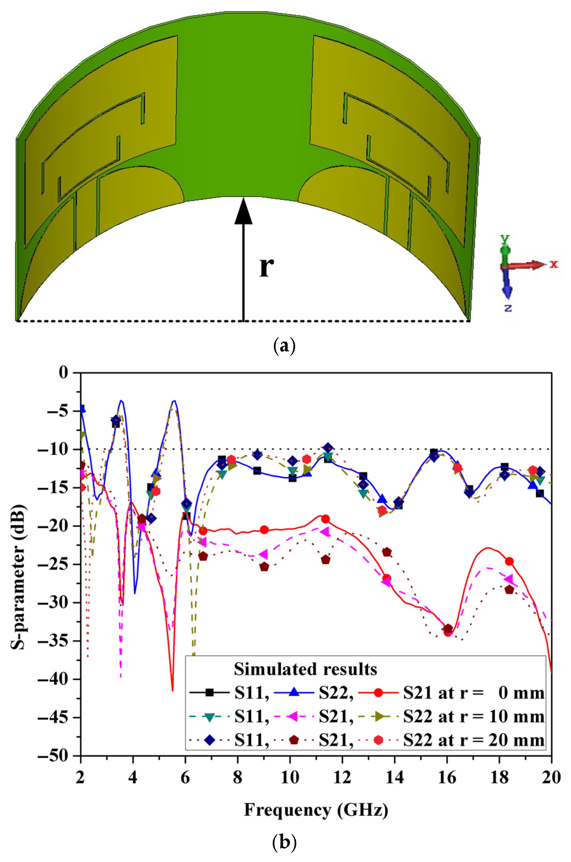
Figure 10a depicts the conformal UWB MIMO antenna configuration with the bending parameter r, representing the extent of curvature when affixed to cylindrical surfaces. To assess the resilience of the suggested design under varying bending situations, the S-parameter responses for r = 0, 10, and 20 mm are illustrated in Figure 10b. The impact on the reflection coefficients (S11 and S22) is depicted in Figure 10b. The reflection coefficients for both ports consistently remain below −10 dB throughout the majority of the UWB working band, hence affirming effective wideband impedance matching. When the antenna is flat (r = 0 mm), pronounced notch bands manifest around 3.71 GHz and 5.78 GHz, where S11 and S22 increase sharply above −5 dB, signifying a deliberate impedance mismatch that attenuates energy at these frequencies. As the antenna curvature increases to r = 10 mm and r = 20 mm, the overall impedance matching experiences modest perturbations, accompanied by tiny frequency shifts and fluctuations in notch depth. Nonetheless, the notches remain distinctly visible, indicating that the dual-notch mechanism is resilient to conformal bending. The transmission coefficient (S21) demonstrates inter-port isolation consistently below −15 dB throughout the majority of the UWB band for all curvature scenarios, signifying minimal mutual coupling appropriate for MIMO functionality. At the notch frequencies of 3.71 GHz and 5.78 GHz, S21 exhibits a further decline (becoming more negative), indicating that the antenna not only mitigates radiation but also improves port isolation at the notched bands. This is advantageous in dual-port operation, as it diminishes the likelihood of interference coupling between parts at the rejected channels.
Therefore, it can be observed that although slight frequency shifts and variations in impedance matching occur with increasing curvature due to bending, the dual-notch characteristics at 3.71 GHz and 5.78 GHz, as well as the port-to-port isolation, remain preserved, confirming the antenna’s stable performance under mechanical deformation.
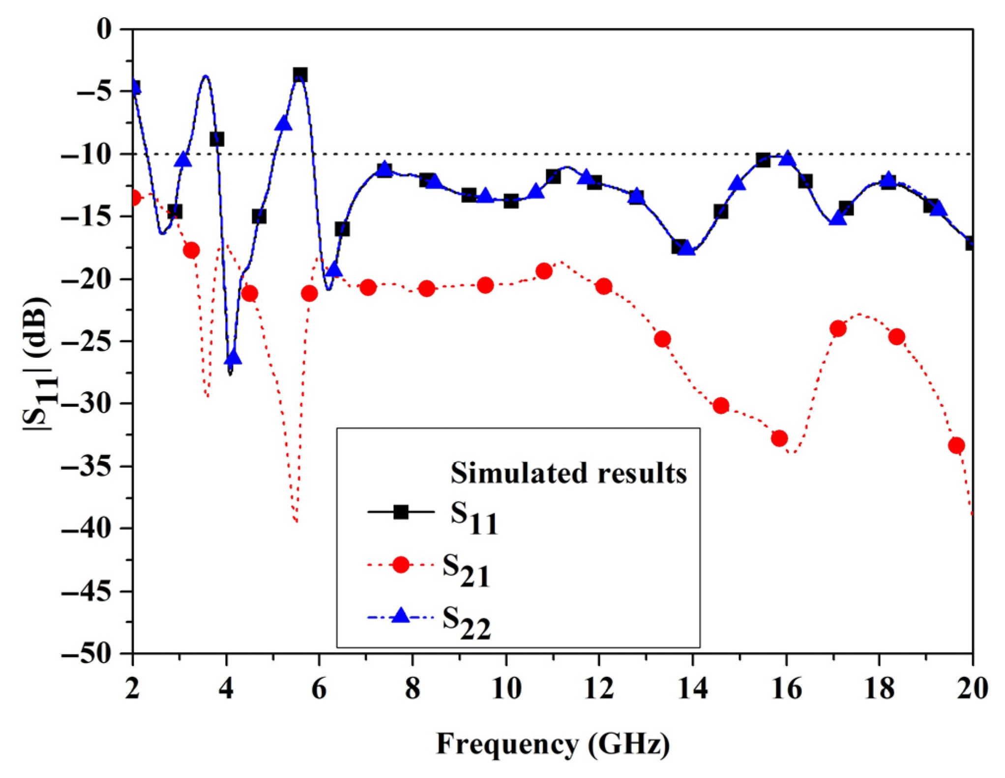
The optimum parameter values derived from prior studies are used to simulate the antenna characteristics, displayed in Figure 11. Figure 11 illustrates the reflection coefficients for port 1 (S11) and port 2 (S22), as well as the coefficient of transmission (S21) of the presented antenna. The comparison of the reflection coefficient features of S11 and S22 produced similar results. Both values were below −10 dB across the UWB spectrum, except for the notched frequency ranges for WiMAX and WLAN, whereas the transmission coefficient (S21) demonstrated low mutual coupling under −16 dB throughout the full UWB band. The MIMO performance of the antenna was improved by modifying the distance (d) between the antenna components.

3.2. Radiation Pattern of the Simulation

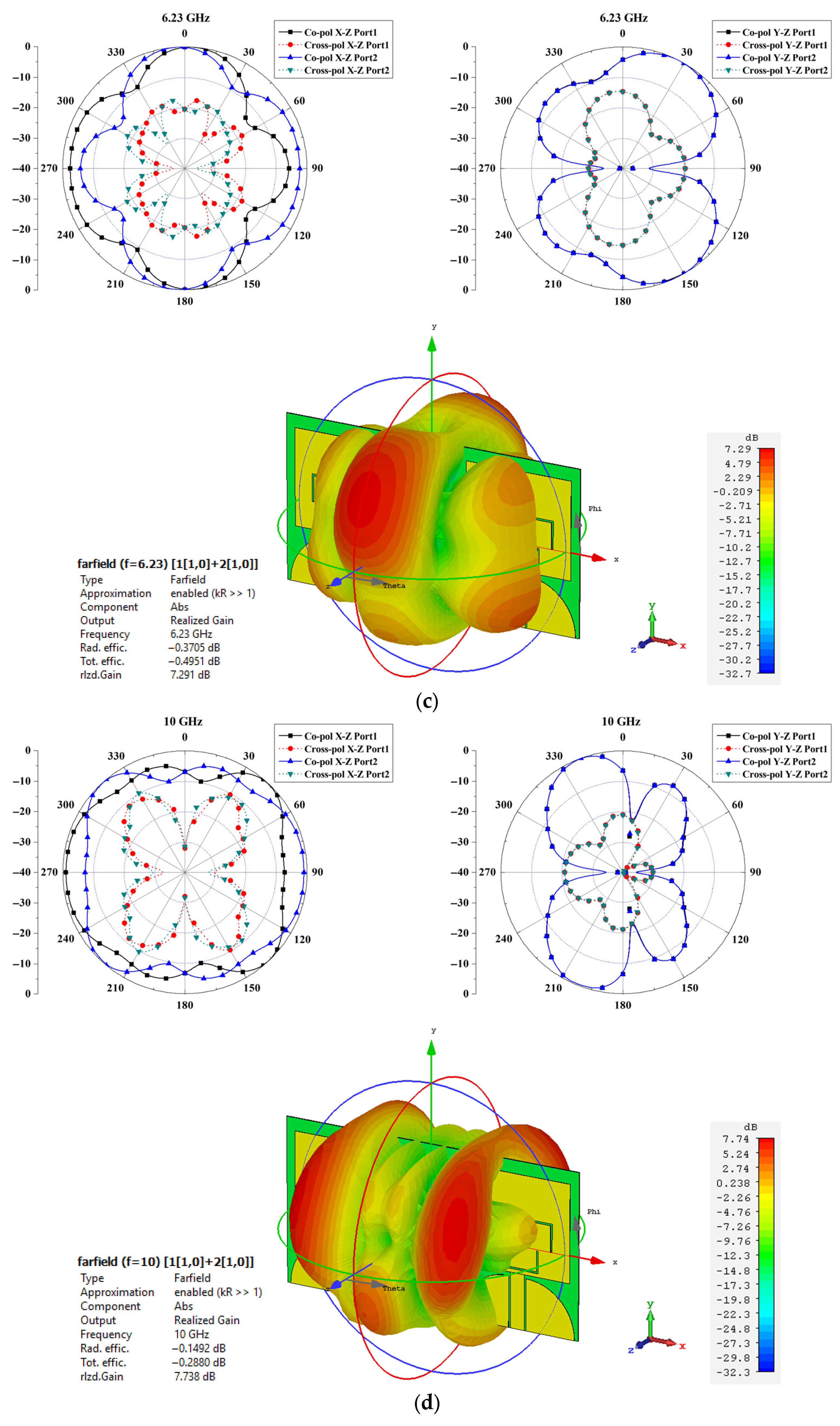
This section assesses the radiation attributes of the suggested UWB MIMO antenna for wireless communication systems across multiple frequencies. Radiation patterns immediately indicate the antenna’s efficacy in consistently transmitting and receiving signals across various directions, a crucial element for assuring dependable MIMO performance and spatial signal diversity. Figure 12a–d displays the simulated two-dimensional and three-dimensional radiation patterns of both co-polarization and cross-polarization components in the XZ and YZ planes at four specified frequencies: 2.6 GHz, 4.1 GHz, 6.23 GHz, and 10 GHz. The simulations were performed by energizing one port at a time, while the other was terminated using a 50-ohm load to isolate the behavior of each particular port. This port-switching technique facilitates the evaluation of radiation symmetry and consistency, essential for reliable MIMO functionality. At low and mid frequencies (2.6 and 4.1 GHz), as seen in Figure 12a,b, the radiation patterns exhibited consistency and symmetry between both ports, indicating strong port-to-port similarity. The XZ plane had omnidirectional properties, advantageous for uniform coverage, but the YZ plane revealed bidirectional characteristics, which may enhance spatial diversity. Figure 12c,d depicts the radiation patterns at higher frequencies (6.23 and 10 GHz). Comparable symmetry and consistency were observed; however, increasing distortion in pattern shape occurred owing to the appearance of higher-order electromagnetic modes at increased frequencies. The results indicate that the suggested antenna sustains favorable omnidirectional and bidirectional radiation patterns over the majority of the UWB spectrum, guaranteeing effective spatial coverage and variety. The observed distortion at elevated frequencies suggests a possible constraint in pattern stability that must be considered in high-frequency or high-density implementations.
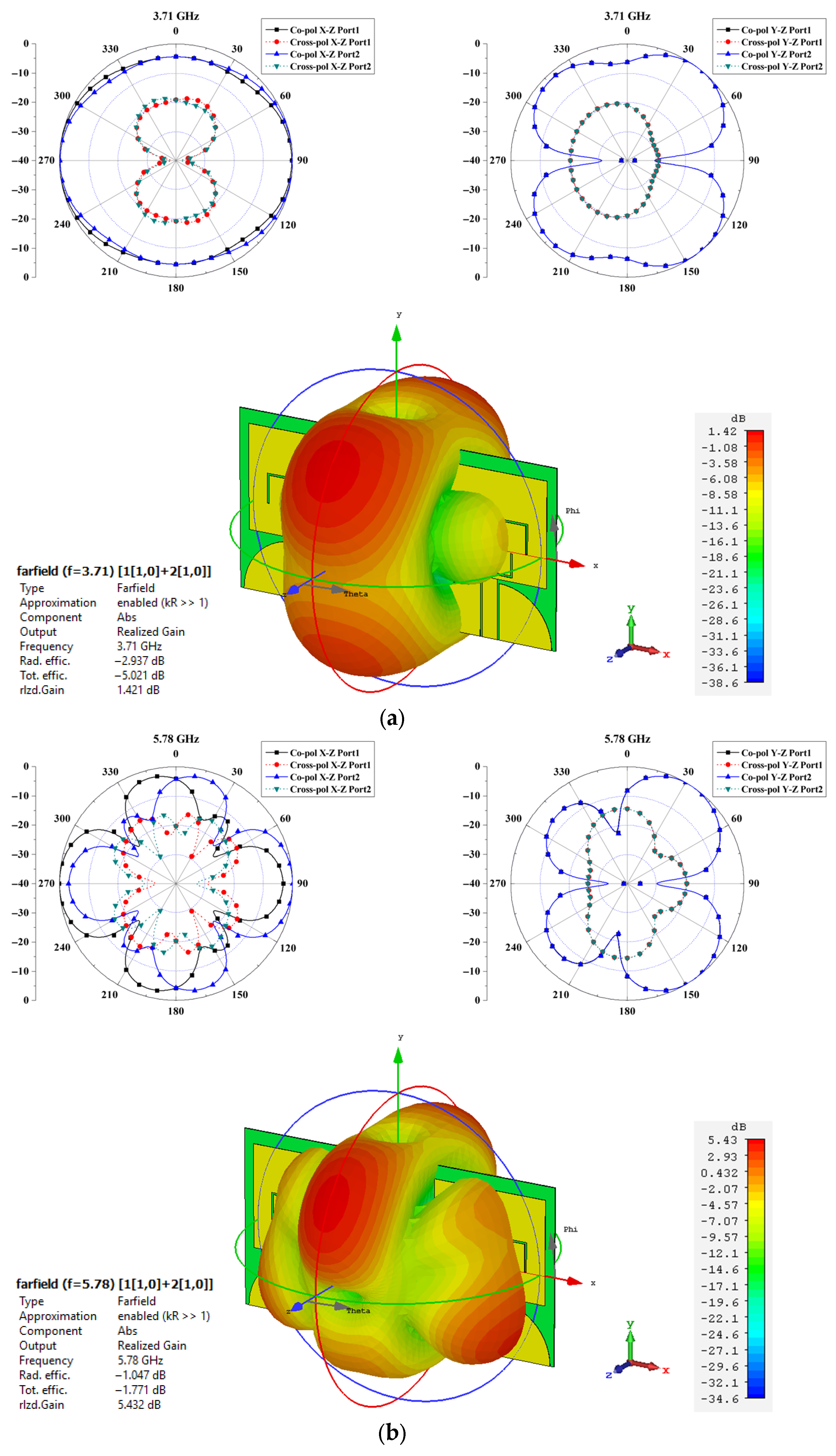
Figure 13a illustrates that the radiation patterns at 3.71 GHz exhibit an almost omnidirectional configuration in the XZ plane and a bidirectional characteristic in the YZ plane. Co-polarization predominates over cross-polarization, signifying steady radiation with high polarization clarity. It is important to note that the gain levels at the boresight direction (0°) are below −5 dB for both planes. The considerable decrease in radiation intensity immediately indicates the suppression effect of the designed notch band at this frequency, hence reducing radiated energy and providing successful interference mitigation. At 5.78 GHz, as depicted in Figure 13b, the antenna demonstrates complicated multi-lobed radiation patterns in both the XZ and YZ planes because of the activation of higher-order modes. Similarly to the 3.71 GHz situation, co-polarization continues to dominate, although cross-polarization becomes marginally more prominent. The boresight direction demonstrates a gain level below −5 dB, confirming that the antenna efficiently attenuates radiated power at the notched frequency. This confirms that the notching technique effectively diminishes unwanted radiation in the primary direction, thereby ensuring efficient rejection of potential interference sources, including WLAN networks at around 5.8 GHz.
The ongoing finding of diminished gain (<−5 dB) at the boresight for both notched frequencies signifies that the antenna’s radiated energy is significantly dampened at these bands. This behavior validates the efficacy of the notched design in attenuating extraneous signals, while the maintained omnidirectional or multi-lobed radiation at alternative angles guarantees dependable coverage within the operating UWB spectrum. Moreover, these radiation attributes correlate well with the return loss (S11) measurements, exhibiting pronounced notches at 3.71 GHz and 5.78 GHz, as well as with the port-to-port isolation findings, confirming that mutual coupling does not impair antenna performance at these attenuated frequencies. Consequently, the suggested dual-notch antenna attains frequency-selective rejection and stable radiation properties, rendering it appropriate for contemporary UWB communication systems.

3.3. Gain and Efficiency

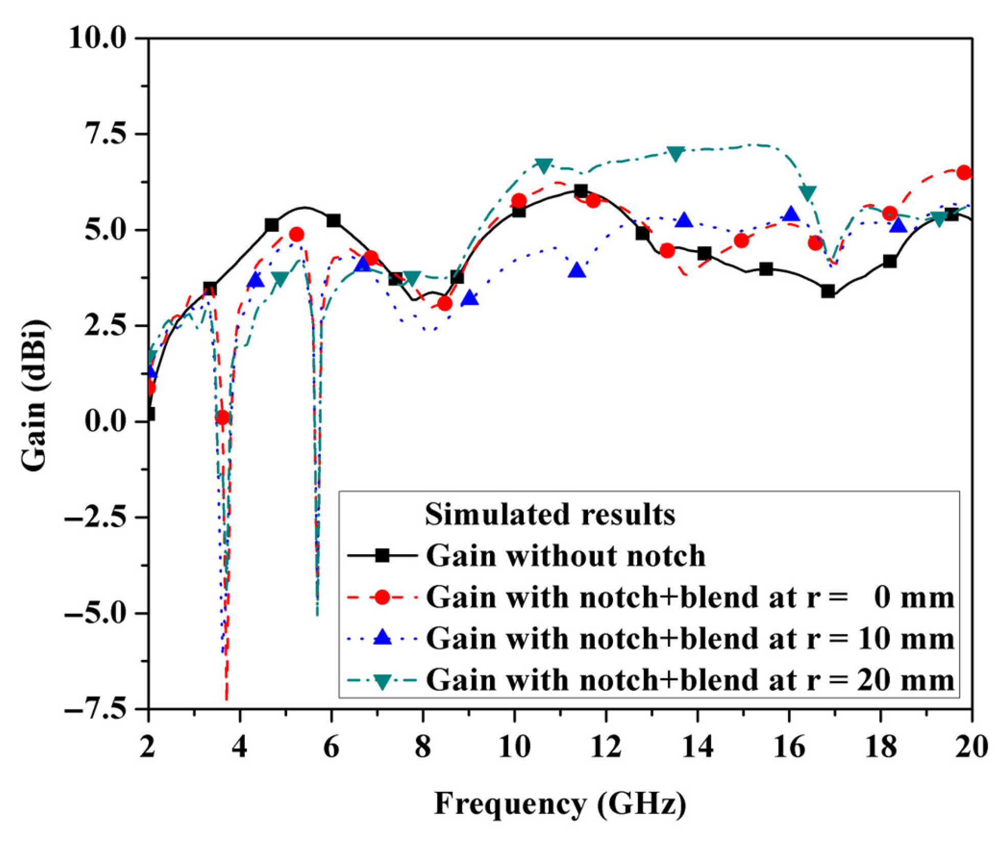
Figure 14 compares the gain simulations of the UWB MIMO antennas with and without band-notch components in the broadside direction. For frequencies of 2.9–13.8 (2.72–13.86) GHz, the gains of both antennas were comparable, ranging from 2.75 to 5.2 (6.23) dBi, with an average of 4.5 dBi. On the other hand, the gain of the UWB MIMO antennas with dual-band notches reduced dramatically at frequencies of 3.5 GHz and 5.5 GHz, which demonstrates the influence of band rejection. Additionally, the parametric modification of the blended antenna length with parameters r = 0, 10, and 20 mm indicated that an increase in the parameter r somewhat diminished the notch depth (from −7.3 dBi at r = 0 mm to around −5 dBi at r = 20 mm) while concurrently enhancing the out-of-band gain. The gain enhancement was particularly significant in the mid- and high-frequency regions, with improvements of 0.9–2.2 dB recorded at 10–14 GHz for r = 20 mm relative to the no-notch condition. Nonetheless, given that the specified operating band of the proposed antenna is 3.1–10.6 GHz, the configuration with r = 0 mm is considered the most appropriate for practical application, as it provides the greatest rejection at 3.5 and 5.5 GHz while ensuring consistent gain performance throughout the intended UWB band. Therefore, the proposed antenna has a reasonable gain over the entire operational band, except for the dual-band notches.
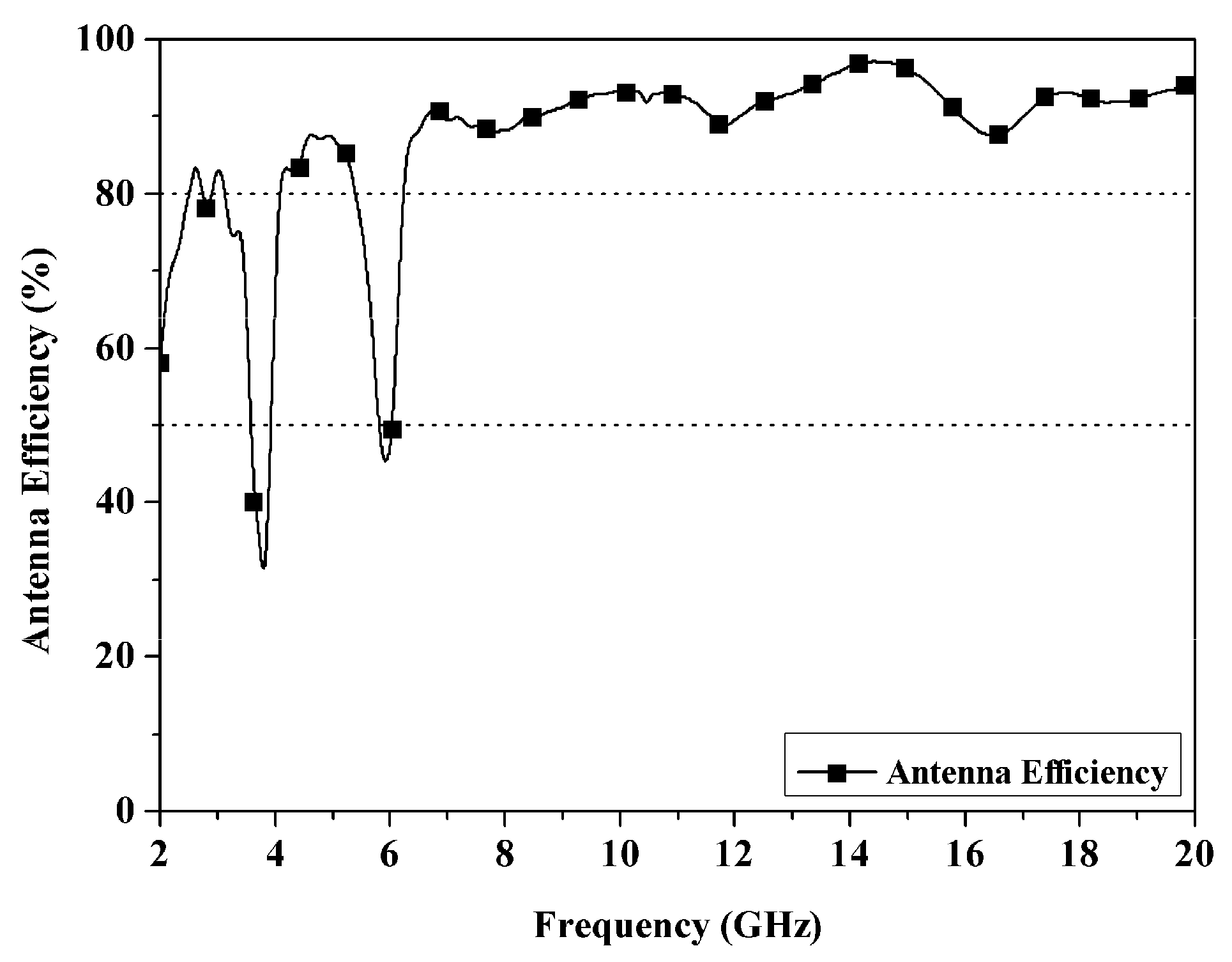
Moreover, the simulation results of antenna efficiency, depicted in Figure 15, clearly demonstrate the antenna’s ability to sustain high radiation performance over its operational bandwidth. The antenna exhibits an efficiency surpassing 80% within the specified ultra-wideband (UWB) frequency range, confirming that the designed structure allows effective impedance matching and ensures efficient radiation with minimal power losses from absorption. Conversely, at the purposely notched bands—aligned with the WiMAX band (3.3–3.7 GHz) and the WLAN band (5.1–5.8 GHz)—the antenna efficiency significantly declines to below 50%. This reduction directly results from the effective application of double U-shaped slot structures, which attenuate radiation in certain frequency ranges through destructive interference and obvious resonances. As a result, negligible electromagnetic energy is emitted at the notched frequencies, thus reducing the possibility of interference with current WiMAX and WLAN systems while maintaining ideal efficiency in other segments of the UWB spectrum.

3.4. Diversity Characteristic of the Simulation

Diversity is an essential characteristic of the MIMO antenna, indicative of its performance. The assessment may use the envelope coefficient correlation (ECC), calculable using S-parameters according to Equation (1) [29,30,31,32,33]. Furthermore, the application of the S parameter for the ECC is a simplification from the far-field result.
E C C = S 11 S 12 + S 21 S 22 2 1 S 11 2 S 21 2 1 S 22 2 S 12 2
A MIMO antenna with superior capability and performance requires a low envelope correlation coefficient (ECC). The ECC should preferably be zero. The practical limit for an uncorrelated MIMO antenna is an ECC of less than 0.5. Figure 16 illustrates the simulated ECC of the proposed antennas, which remained below 0.03 over the whole operational spectrum. This indicates that each antenna element is well segregated, demonstrating that the suggested antenna exhibits superior MIMO performance.

4. Measurement Results

The UWB MIMO antenna with dual-band notches was subsequently fabricated, as seen in Figure 17. To completely evaluate the antenna’s performance for practical UWB MIMO applications, the relevant parameters will be experimentally examined. The evaluation encompassed S-parameters to confirm impedance matching and band-notched behavior, radiation patterns to analyze directional characteristics and field distribution, gain to ascertain signal strength across the frequency spectrum, and ECC to measure isolation and diversity performance among antenna elements.

4.1. S-Parameters

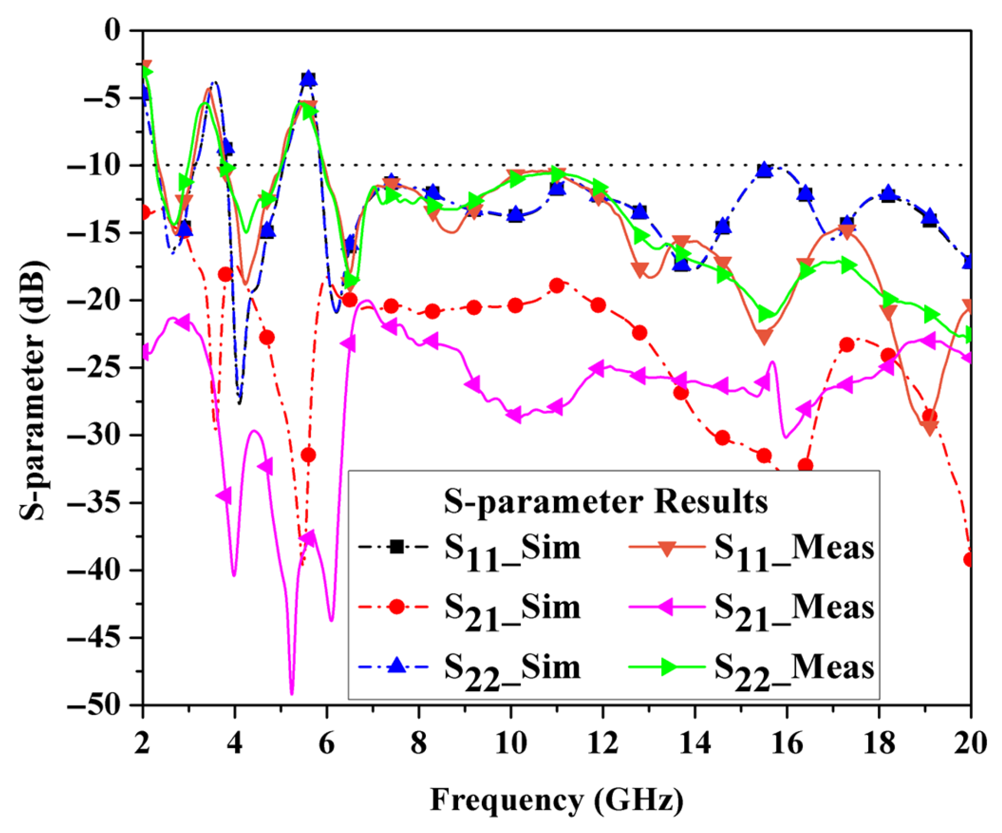
Figure 18 presents the comparison between simulation and measurement results of the antenna parameters S11, S22, and S21. The outcomes of these parameters align with the simulation findings, demonstrating that the UWB MIMO antenna has favorable features. The outcomes of the reflection coefficient parameters S11 and S22 are similar. Both characteristics remain below −10 dB over the UWB frequency spectrum, except for the 3.1–3.8 GHz and 5–6 GHz frequency ranges. The transmission coefficient of parameter S21 exhibits a minimal mutual exclusivity below −20 dB throughout the UWB band, aligning well with the simulation results. It is also evident from Figure 18 that slight shifts occur between the simulated and measured resonance frequencies of the dual-notch bands. These variations are primarily ascribed to manufacturing tolerances and the manual assembly of the prototype. Nonetheless, the overall concordance between the two results affirms the consistency and reliability of the suggested antenna.

4.2. Radiation Pattern

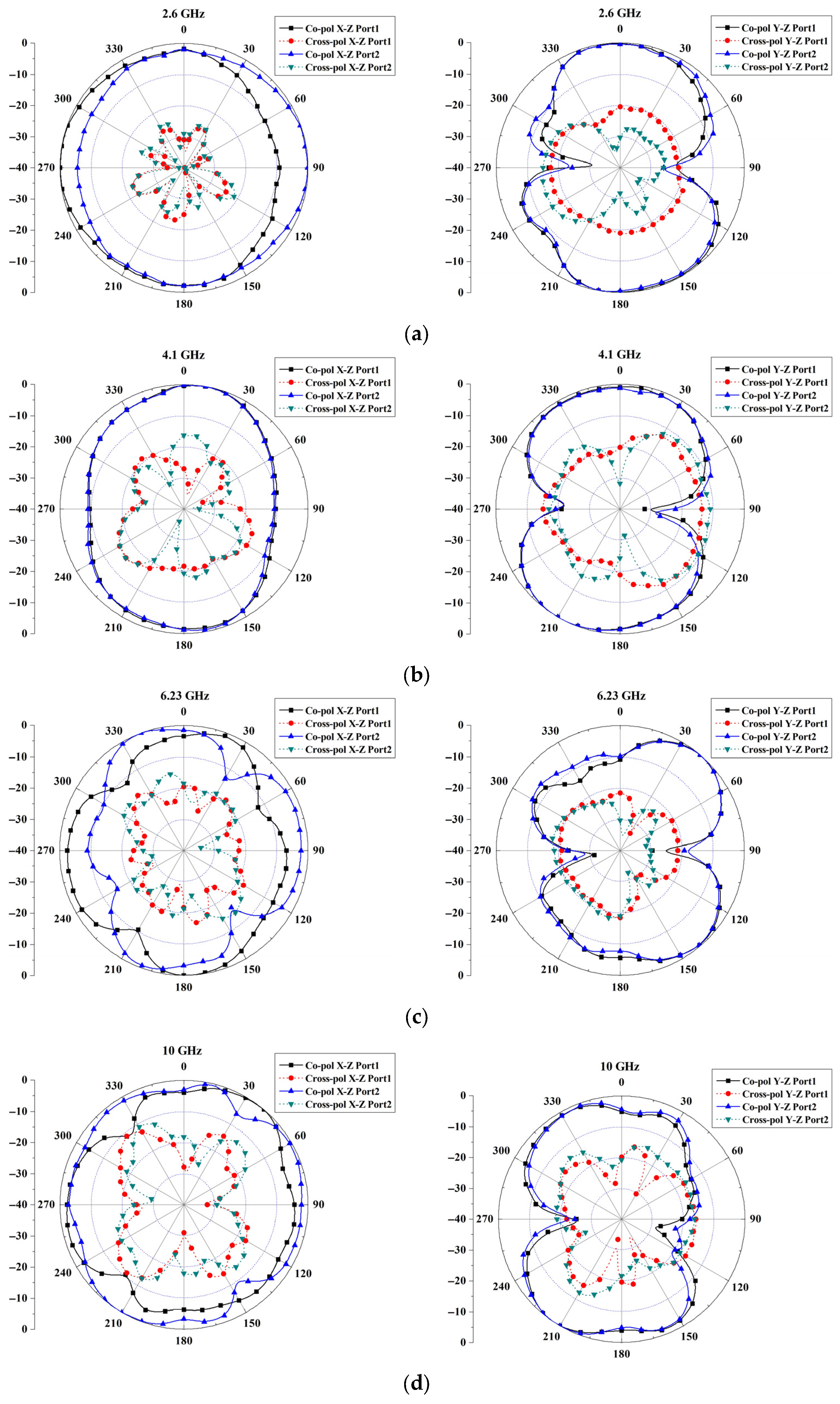
This section presents the examination of the antenna’s measured radiation patterns. The radiation patterns of co-polarization and cross-polarization in the XZ plane and YZ plane at 2.6 GHz, 4.1 GHz, 6.23 GHz, and 10 GHz are displayed in Figure 19a–d. The measurement method was executed according to the simulation. Figure 19a,b depicts the results of the low-to-medium-frequency radiation patterns, whereas Figure 19c,d represent the medium-to-high-frequency radiation patterns. The measured patterns agreed with the simulated patterns, and the measurement results for each frequency at ports 1 and 2 were consistent. The patterns on the XZ plane were omnidirectional, whereas those on the YZ plane were bidirectional, as demonstrated by these data. The pattern, however, gradually deformed as the frequency increased due to the higher-order mode of electromagnetic waves.

4.3. Gain

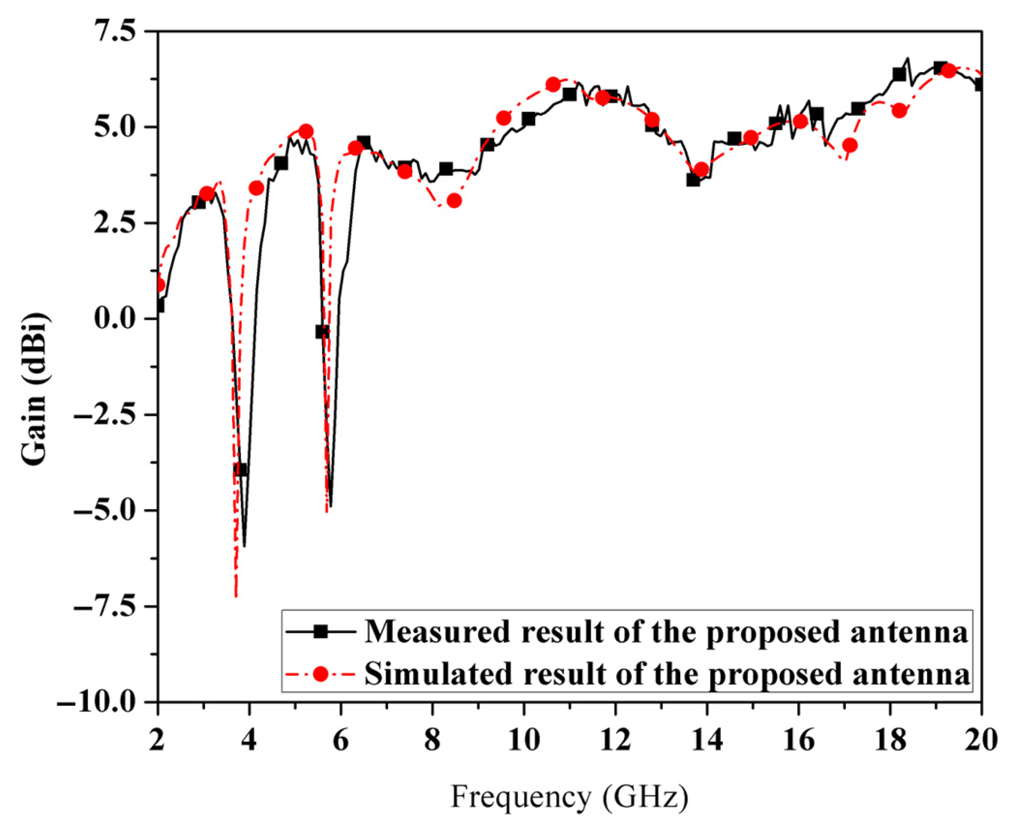
This section investigates the measured gains of the UWB MIMO antenna with dual-band notches. The measured antenna gains were similar to those expected from the simulation. Figure 20 demonstrates that antenna gains ranged from 2.65 dBi to 5 dBi over the entire UWB band, excluding the notch frequencies of 3.5 GHz and 5.5 GHz, where they fell substantially. Consequently, the fabricated antenna achieved good gains across the entire operating frequency band, excluding the frequency bands affected by the rejection elements. It is also observed in Figure 20 that slight discrepancies exist between the simulated and measured results in terms of notch frequencies and gain levels. These deviations are primarily attributed to fabrication tolerances and the manual assembly of the antenna prototype. Nevertheless, the overall agreement between simulation and measurement validates the proposed design and confirms the reliability of the antenna performance.

4.4. Diversity Characteristics

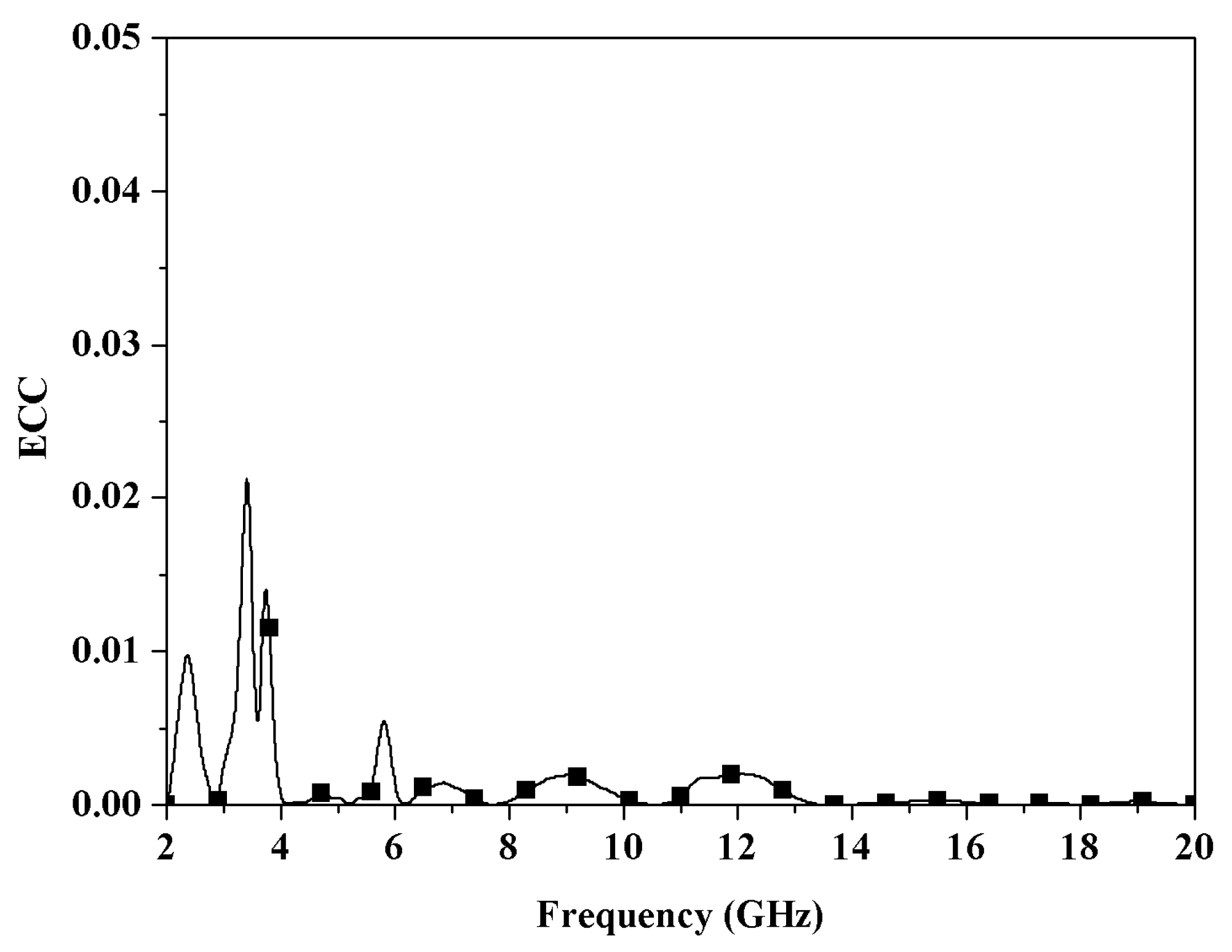
The ECC was analyzed. Figure 21 demonstrates the measured ECC of the fabricated antenna. It can be seen that the ECC was less than 0.01 of the entire operating bandwidth, indicating that the isolation between nearby antennas was acceptable. The antenna’s MIMO performance was excellent.
The simulation and measurement results of the dual-band-notched UWB MIMO antenna exhibit strong consistency across several parameters, including S-parameters, radiation patterns, gain, and ECC. In certain instances, such as mutual coupling (S21) and ECC, the empirical results surpass the simulated predictions, suggesting that the designed antenna configuration exhibits superior performance and is appropriate for MIMO applications necessitating both optimal separation and efficient attenuation of WiMAX/WLAN interference.
The comparison between the suggested antenna and the previously examined antennas is presented in Table 3. This research is exceptional for bandwidth, signal separation, slender structure, and little loss in comparison to previous studies. Consequently, it is appropriate for UWB MIMO systems in portable devices that need high performance within a small and lightweight form factor.

5. Conclusions

We proposed a flexible and compact UWB MIMO with a dual-band-notched antenna based on Mylar® polyester film. The antenna has a simple structure and is flexible and compact. Dual-notch frequencies were established by incorporating an inverted U-slot and a U-slot to eliminate interference for the WLAN and WiMAX systems, respectively. The results demonstrated that the simulation and measurements were consistent. The antenna provided a good impedance bandwidth with S11 < −10 dB throughout the UWB band, except at a notched frequency covering 3.3–3.7 GHz and 5.1–5.8 GHz. In addition, the mutual coupling was low, with S21 < −15 dB covering the operating band. On the XZ plane, the radiation patterns were omnidirectional, while they were bidirectional on the YZ plane. In addition, the presented antenna featured a high gain and a negligible ECC. Consequently, our developed antenna had an acceptable MIMO performance, could reduce interference frequencies, and was efficient for a variety of portable UWB applications in which simulation and measurement are consistent.
Moreover, the proposed UWB-MIMO antenna with dual-band notches offers several advantages over existing designs. First, it is thinner, making it ideal for compact portable applications, where space and weight are limited. Additionally, the larger bandwidth supports versatile performance across various frequencies, enabling adaptability in dynamic communication environments. The design also incorporates a lower-loss tangent, reducing energy losses and enhancing signal transmission efficiency, which results in improved signal clarity and reliability. Altogether, this antenna’s thin profile, wide bandwidth, and low loss tangent provide an innovative and efficient solution for WiMAX and WLAN communications, as evidenced by the comparative results from other research in Table 3.
These results offer a practical framework for researchers aiming to develop versatile and compact UWB MIMO antennas with dual-band rejection characteristics. The method demonstrated can be applied to various substrates and frequency ranges, enabling a broad range of research in flexible electronics, wearable technology, and integrated communication systems. The impressive correlation between simulation and experimental findings confirms the design’s reliability, making it a strong candidate for use in future low-profile UWB MIMO systems.
Author Contributions

Conceptualization, V.C., W.C., C.R., N.W. and C.M.; data curation, V.C., W.C., C.R., P.R., M.T. and C.M.; formal analysis, V.C., P.R., N.W. and C.M.; funding acquisition, P.R., M.T., N.W. and P.A.; investigation, C.R., P.R., M.T., N.W. and C.M.; methodology, V.C., W.C., C.R., P.R., N.W. and C.M.; software, V.C., W.C., P.R., M.T., N.W. and P.A.; supervision, P.R. and C.M.; validation, C.R., P.R., N.W. and C.M.; writing—original draft, V.C., C.R., N.W. and C.M.; writing—review and editing, P.R., N.W. and C.M. All authors have read and agreed to the published version of the manuscript.

Funding

This research was funded by National Science, Research and Innovation Fund (NSRF) and King Mongkut’s University of Technology North Bangkok with Contact no. KMUTNB-FF-68-A-03.

Data Availability Statement

This research includes the original contributions offered in the article. Additional queries may be sent to the corresponding author.

Acknowledgments

The authors would like to express their sincere gratitude to the Department of Electronics and Telecommunication Engineering, Faculty of Engineering, Rajamangala University of Technology Thanyaburi, and the School of Engineering, King Mongkut’s Institute of Technology Ladkrabang, for their technical and experimental support. The authors also acknowledge the use of CST Microwave Studio software provided by the respective institutions for antenna simulation.

Conflicts of Interest

The authors declare no conflicts of interest.

References

  1. Rakluea, P.; Wongsin, N.; Mahatthanajatuphat, C.; Aroonmitr, P.; Jangjing, T.; Rakluea, C.; Chanwattanapong, W.; Chudpooti, N. Flexible Thin Film-Based Triple Port UWB MIMO Antenna with Modified Ground Plane for UWB, WLAN, WiMAX, WPAN and 5G Applications. IEEE Access 2023, 11, 107031–107048. [Google Scholar] [CrossRef]
  2. Moeikham, P.; Mahatthanajatuphat, C.; Akkaraekthalin, P. A Compact Ultrawideband Monopole Antenna with 5.5 GHz Notched Band. Prog. Electromagn. Res. C 2012, 26, 13–27. [Google Scholar] [CrossRef]
  3. Gao, Y.; Wang, Z.; Tang, H.; Luo, Q.; Hu, W. Ultrawideband Transmit-Reflect-Array Antenna for 6G Communication. IEEE Antennas Wirel. Propag. Lett. 2024, 23, 3669–3673. [Google Scholar] [CrossRef]
  4. Park, S.; Jung, K.Y. Novel Compact UWB Planar Monopole Antenna Using a Ribbon-Shaped Slot. IEEE Access 2022, 10, 61951–61959. [Google Scholar] [CrossRef]
  5. Aroonmitr, P.; Rakluea, C.; Wongsin, N.; Rakluea, P.; Jangjing, T.; Chanwattanapong, W. A Super Thinnest Film Antenna for Wireless Communications with Notched Characteristics. In Proceedings of the 2023 IEEE International Symposium on Antennas and Propagation (ISAP), Kuala Lumpur, Malaysia, 1–2 November 2023. [Google Scholar]
  6. Sangpet, P.; Chanwattanapong, W.; Sangmook, C.; Mahatthanajatuphat, C.; Jangjing, T.; Chudpooti, N.; Rakluea, P.; Wongsin, N. Design of Ultra-Wideband Antipodal Vivaldi Antenna with Improving Impedance Matching using Elliptical Stub for GPR Applications. In Proceedings of the 2025 13th International Electrical Engineering Congress (iEECON), Hua Hin, Thailand, 5–7 March 2025. [Google Scholar]
  7. Jeong, K.P.; Jae, H.P.; Kyung, T.K. Multipath Signal Mitigation for Indoor Localization Based on MIMO FMCW Radar System. IEEE Internet Things J. 2024, 11, 2618–2629. [Google Scholar]
  8. Kumkhet, B.; Rakluea, P.; Wongsin, N.; Sangmahamad, P.; Thaiwirot, W.; Mahatthanajatuphat, C. Ultra Wideband Fabric MIMO Antenna for Future 5G Applications. In Proceedings of the 2022 19th International Conference on Electrical Engineering/Electronics, Computer, Telecommunications and Information Technology (ECTI-CON), Prachuap Khiri Khan, Thailand, 24–27 May 2022. [Google Scholar]
  9. Patwary, A.B.; Mahbub, I. 4 × 4 UWB Phased Array Antenna with >51° Far-Field Scanning Range for Wireless Power Transfer Application. IEEE Open J. Antennas Propag. 2024, 5, 354–367. [Google Scholar] [CrossRef]
  10. Tang, H.; Bulger, C.J.; Rovere, T.; Zheng, B.; An, S.; Li, H.; Dong, Y.; Haerinia, M.; Fowler, C.; Gonya, S.; et al. A Low-Profile Flexible Dual-Band Antenna with Quasi-Isotropic Radiation Patterns for MIMO System on UAVs. IEEE Antennas Wirel. Propag. Lett. 2023, 22, 49–53. [Google Scholar] [CrossRef]
  11. Fang, Y.; Liu, Y.; Jia, Y.; Liang, J.; Zhang, H.H. Reconfigurable Structure Reutilization Low-SAR MIMO Antenna for 4G/5G Full-Screen Metal-Frame Smartphone Operation. IEEE Antennas Wirel. Propag. Lett. 2023, 22, 1219–1223. [Google Scholar] [CrossRef]
  12. Wong, K.L.; Huang, Y.Y.; Li, W.Y. Compact 8-Port 2 × 2 Array Based on Dual-Polarized Patch Antennas with Modified Cavity Field Distribution for Enhanced Port Isolation for 5G IoT Device MIMO Antennas. IEEE Access 2024, 12, 79311–79326. [Google Scholar] [CrossRef]
  13. Lu, W.; Gang, W.; Qi, Z. Suppressing Mutual Coupling of MIMO Antennas with Parasitic Fragment-type Elements. In Proceedings of the 46th European Microwave Conference (EuMC), London, UK, 4–6 October 2016. [Google Scholar]
  14. Huang, H.F.; Zhang, Z.P. Mutual Coupling Reduction of a Very Compact UWB-MIMO Linearly Tapered Slot Antenna Using a Simple Stepped Slot. In Proceedings of the 2017 International Applied Computational Electromagnetics Society Symposium (ACES), Suzhou, China, 1–4 August 2017. [Google Scholar]
  15. Khan, M.S.; Capobianco, A.-D.; Asif, S.M.; Anagnostou, D.E.; Shubair, R.M.; Braaten, B.D. A Compact CSRR-Enabled UWB Diversity Antenna. IEEE Antennas Wirel. Propag. Lett. 2017, 16, 808–812. [Google Scholar] [CrossRef]
  16. Amjad, I.; Omar, A.S.; Arbab, W.A.; Shahid, B. Mutual Coupling Reduction Using F-Shaped Stubs in UWB-MIMO Antenna. IEEE Access 2018, 6, 2755–2759. [Google Scholar]
  17. Malekpour, N.; Honarwar, M.A.; Dadgarpur, A.; Virdee, B.S.; Denidni, T.A. Compact UWB MIMO Antenna with Band-Notched Characteristic. Microw. Opt. Technol. Lett. 2017, 59, 1037–1041. [Google Scholar] [CrossRef]
  18. Liu, Y.-Y.; Tu, Z.H. Compact Differential Band-Notched Stepped-Slot UWB-MIMO Antenna with Common-Mode Suppression. IEEE Antennas Wirel. Propag. Lett. 2017, 16, 593–596. [Google Scholar] [CrossRef]
  19. Wu, W.; Yuan, B.; Wu, A. A Quad-Element UWB-MIMO Antenna with Band-Notch and Reduced Mutual Coupling. Int. J. Antennas Propag. 2018, 1, 1–10. [Google Scholar]
  20. Azarm, B.; Nourinia, J.; Ghobadi, C.; Majidzadeh, M.; Hatami, N. A Compact WiMAX Band-Notched UWB MIMO Antenna with High Isolation. Radioengineering 2018, 27, 983–989. [Google Scholar] [CrossRef]
  21. Chandel, R.; Gautam, A.K.; Rambabu, K. Tapered Fed Compact UWB MIMO-Diversity Antenna with Dual Band-Notched Characteristics. IEEE Trans. Antennas Propag. 2018, 66, 1677–1684. [Google Scholar] [CrossRef]
  22. Jetti, C.R.; Nandanavanam, V.R. Trident-Shape Strip Loaded Dual Band-Notched UWB MIMO Antenna for Portable Device Applications. AEU Int. J. Electron. Commun. 2018, 83, 11–21. [Google Scholar] [CrossRef]
  23. Chaabane, A.; Babouri, A. Dual Band Notched UWB MIMO Antenna for Surface Penetrating Application. Adv. Electromagn. 2019, 8, 6–15. [Google Scholar] [CrossRef]
  24. Thakur, E.; Jaglan, N.; Gupta, S.D.; Kanaujia, B.K. A Compact Notched UWB MIMO Antenna with Enhanced Performance. Prog. Electromagn. Res. C 2019, 91, 39–53. [Google Scholar] [CrossRef]
  25. Pannu, P.; Sharma, D.K. A Compact Four Port UWB-MIMO Antenna with Notch Band Characteristics and High Isolation. In Proceedings of the Fourth International Conference on Communication and Electronics Systems (ICCES), Coimbatore, India, 17–19 July 2019. [Google Scholar]
  26. Fan, C.; Zhao, W.; Chen, K.; Zhao, J.; Jiang, T.; Feng, Y. Optically Transparent Conformal Reflectarray with Multi-Angle Microwave Efficient Scattering Enhancement. Adv. Optical Mater. 2024, 12, 2400151. [Google Scholar] [CrossRef]
  27. Beccaria, M.; Pirinoli, P.; Yang, F. Preliminary results on Conformal Transmitarray Antennas. In Proceedings of the 2018 IEEE International Symposium on Antennas and Propagation & USNC/URSI National Radio Science Meeting, Boston, MA, USA, 8–13 July 2018. [Google Scholar]
  28. Yoo, I.; Smith, D.R. Design of Conformal Array of Rectangular Waveguide-Fed Metasurfaces. IEEE Trans. Antennas Propag. 2022, 70, 6060–6065. [Google Scholar] [CrossRef]
  29. Altaf, A.; Iqbal, A.; Smida, A.; Smida, J.; Althuwayb, A.A.; Kiani, S.H.; Alibakhshikenari, M.; Falcone, F.; Limiti, E. Isolation Improvement in UWB-MIMO Antenna System Using Slotted Stub. Electronics 2020, 9, 1582. [Google Scholar] [CrossRef]
  30. Kumkhet, B.; Rakluea, P.; Wongsin, N.; Sangmahamad, P.; Thaiwirot, W.; Mahatthanajatuphat, C.; Chudpooti, N. SAR Reduction Using Dual Band EBG Method Based on MIMO Wearable Antenna for WBAN Applications. AEU Int. J. Electron. Commun. 2023, 160, 154525. [Google Scholar] [CrossRef]
  31. Islam, H.; Das, S.; Ali, T.; Bose, T.; Dhar, S.; Rai, B.; Kumar, P. Compact Circularly Polarized 2 and 4 Port Multiple Input Multiple Output Antennas with Bandstop Filter Isolation Technique. Alex. Eng. J. 2023, 66, 357–376. [Google Scholar] [CrossRef]
  32. Ghawbar, F.; Sukur, J.A.; Majid, H.A.; Bait-Suwailam, M.M.; Al-Lawati, H.; Amer, A.A.G.; Saparudin, F.A.; Ghafar, A.S.A. Highly Self-Isolated 12-MIMO Antenna Elements for 5G Mobile Applications. Electronics 2025, 14, 1424. [Google Scholar] [CrossRef]
  33. Yang, Q.; Zhang, C.; Cai, Q.; Loh, T.H.; Liu, G. A MIMO Antenna with High Gain and Enhanced Isolation for WLAN Applications. Electronics 2022, 12, 2279. [Google Scholar] [CrossRef]
Figure 1. Architecture of the dual-band-notched UWB antenna.
Electronics 14 03363 g001
Figure 2. Configuration of the dual-band-notched UWB MIMO antenna.
Electronics 14 03363 g002
Figure 3. Current dispersion on the proposed antenna at a notch frequency of 3.55 GHz when excited at (a) port 1 and (b) port 2.
Electronics 14 03363 g003
Figure 4. Current dispersion on the proposed antenna at a notch frequency of 5.58 GHz when excited at (a) port 1 and (b) port 2.
Electronics 14 03363 g004
Figure 5. The evolution processes of the designed antennas.
Electronics 14 03363 g005
Figure 6. |S11| simulated results of the various antennas.
Electronics 14 03363 g006
Figure 7. The coefficient of reflection results of the proposed antenna vary with the parameter of LS1.
Electronics 14 03363 g007
Figure 8. The coefficient of reflection results of the proposed antenna vary with the LS2 parameter.
Electronics 14 03363 g008
Figure 9. The transmission coefficient results from adjusting the distance (d) between the two adjacent antennas.
Electronics 14 03363 g009
Figure 10. (a) The curved UWB MIMO antenna configuration with parameter r and (b) simulation results of the coefficients of reflection and transmission at ports 1 and 2 for the curve UWB MIMO antenna with varying parameter r of 0 mm, 10 mm, and 20 mm.
Electronics 14 03363 g010
Figure 11. The simulation results of the coefficients of reflection and transmission at ports 1 and 2 for the proposed UWB antenna.
Electronics 14 03363 g011
Figure 12. Simulated radiation patterns of the suggested antenna at (a) 2.6 GHz, (b) 4.1 GHz, (c) 6.23 GHz, and (d) 10 GHz.
Electronics 14 03363 g012aElectronics 14 03363 g012b
Figure 13. Simulated radiation patterns of the proposed antenna at dual-notch frequencies of (a) 3.71 GHz and (b) 5.78 GHz.
Electronics 14 03363 g013
Figure 14. Simulated gain of the suggested antenna with and without the notch in the broadside direction when altering r = 0, 10, 20 mm.
Electronics 14 03363 g014
Figure 15. Simulated efficiency of the proposed antenna with dual-band notch.
Electronics 14 03363 g015
Figure 16. Simulated ECC of proposed antennas.
Electronics 14 03363 g016
Figure 17. The fabrication of the proposed antenna.
Electronics 14 03363 g017
Figure 18. Comparison simulation and measured S-parameters S11, S21, and S22 of the proposed antenna with dual-notch band.
Electronics 14 03363 g018
Figure 19. Measured radiation patterns in the XZ and YZ planes of the suggested antenna at (a) 2.6 GHz, (b) 4.1 GHz, (c) 6.23 GHz, and (d) 10 GHz.
Electronics 14 03363 g019
Figure 20. Comparison of simulated and measured broadside gain for the suggested antenna.
Electronics 14 03363 g020
Figure 21. Measured value of ECC for the fabricated antenna.
Electronics 14 03363 g021
Table 1. Initial dimensions of the dual-band-notched UWB antenna.
ParameterWWPWS1WS2Wn1Wn2Wf
Dimensions (mm)35300.50.520124
ParameterWgG1G2SLLPLS1
Dimensions (mm)1411.510.541.526.57.5
ParameterLS2Ln1Ln2LfLght
Dimensions (mm)80.50.515140.30.1
Table 2. Initial dimensions of the dual-band-notched UWB MIMO antenna.
ParameterWMLMd
Dimensions (mm)854520
Table 3. Comparison of the significant characteristics between the proposed antenna and other research.
Ref. No.Antenna Dimensions (Volume) (mm3)Substrate (Ʃr)Freq. (GHz)
(%BW)
Gain (dBi)Notched Band
(GHz)
No. of NotchesECCLoss TangentDielectric ConstantNo. of Ports
[18]44 × 44 × 1.6FR-42.95–10.8
114.18%
2.4–4.05.10–5.9510.040.024.48
[19]60 × 60 × 1.6FR-43.0–16.2
137.5%
8.44.0–5.21-0.024.44
[20]25 × 38 × 1.6FR-42.2–10.8
132.30%
1–4.53.3–3.810.030.024.42
[21]18 × 34 × 1.6FR-42.93–20
148.89%
0–75.1–5.8 and 6.7–7.120.010.024.42
[22]22 × 26 × 0.8FR-43.11–11.8
116.57%
3.6–65.4–5.86 and 7.6–8.420.030.024.42
This work85 × 45 × 0.3Mylar-polys2.29–20
158.91%
4.5–6.233.3–3.7 and 5.1–5.82<0.010.0093.22
Disclaimer/Publisher’s Note: The statements, opinions and data contained in all publications are solely those of the individual author(s) and contributor(s) and not of MDPI and/or the editor(s). MDPI and/or the editor(s) disclaim responsibility for any injury to people or property resulting from any ideas, methods, instructions or products referred to in the content.