Article

A Real-Time UWB-Based Device-Free Localization and Tracking System

1
Institute of Advanced Technology, China Academy of Electronics and Information Technology, Beijing 100041, China
2
School of Information and Electronics, Beijing Institute of Technology, Beijing 100081, China
*
Author to whom correspondence should be addressed.
Electronics 2025, 14(17), 3362; https://doi.org/10.3390/electronics14173362
Submission received: 10 July 2025 / Revised: 15 August 2025 / Accepted: 21 August 2025 / Published: 24 August 2025
(This article belongs to the Special Issue Technology of Mobile Ad Hoc Networks)

Abstract

Device-free localization and tracking (DFLT) has emerged as a promising technique for location-aware Internet-of-Things (IoT) applications. However, most existing DFLT systems based on narrowband sensing networks suffer from reduced accuracy in indoor environments due to the susceptibility of received signal strength (RSS) measurements to multipath interference. In this paper, we propose a real-time DFLT system leveraging ultra-wideband (UWB) sensors. The system estimates target-induced shadowing using two UWB RSS measurements, which are shown to be more resilient to multipath effects compared to their narrowband counterparts. To enable real-time tracking, we further design an efficient measurement protocol tailored for UWB networks. Field experiments conducted in both indoor and outdoor environments demonstrate that our UWB-based system significantly outperforms its traditional narrowband DFLT solutions in terms of accuracy and robustness.

1. Introduction

The development of wireless sensing technologies for location awareness has been driven continuously by ubiquitous wireless edge devices (e.g., WiFi [1], Zigbee [2], RFID [3], Bluetooth [4], etc.). People can be located in both device-based and device-free ways. With the advantage of being non-invasive and not requiring people collaboration, device-free localization and tracking (DFLT) has become a promising technology and attracted considerable attention over the past decade. Researchers’ efforts have demonstrated the ability of DFLT in various applications of through-wall tracking, area-of-interest mapping, smart monitoring, roadside surveillance, healthcare, and military operations.
DFLT usually utilizes easy-to-access received signal strength (RSS) measurements to locate and track a person within a monitored area covered by a wireless sensor network. DFLT techniques are primarily categorized into fingerprint-based [5] and model-based approaches [6,7,8,9]. Fingerprint-based methods tend to be inefficient due to time-consuming training labors required to build a location-labeled RSS database. Model-based approaches, by contrast, are more easily deployable and often perform better by accurately modeling the relationship between RSS changes (attenuations) and the locations of targets and sensors.
In model-based DFLT, RSS changes are affected by target-induced shadowing effects and multipath effects. Shadowing effects caused by targets obstructing the line of sight (LoS) of a link are well examined in [6], which develops an imaging-based DFLT method known as radio tomographic imaging (RTI). DFLT systems perform well in outdoor open LoS-dominant environments but suffer from degraded accuracy in multipath-rich indoor environments because coarse RSS change models take no consideration of multipaths. When a target is located in the vicinity of a link, the signal of that link not only propagates along the LoS but also through multipaths created by target diffraction, scattering and reflection. Moreover, obstructions in indoor environments are also contributors to multipaths besides the target. Typically, narrowband sensors with a small bandwidth (∼2 MHz) operating at 2.4 GHz are used in most DFLT systems, and decoupling the multipath and LoS from narrowband signals is nearly impossible. As a result, target-induced RSS changes depend on the aggregation result of the LoS signal and multipath copies. It is assumed for DFLT that obstructed links should experience an attenuation in RSS, while that of those unaffected links remains unchanged. However, this expectation could be violated when the multipath components are comparable to the LoS component, resulting in an RSS increase in obstructed links or a large RSS fluctuation in unaffected links. The unpredictability of RSS change is detrimental to the performance of narrowband DFLT systems. To reduce multipath effects and enhance the robustness of RSS attenuation, several researchers have proposed methods involving hardware improvement, protocol modifications, and movement assistance, including channel diversity [10], frequency diversity [11,12,13,14], spatial diversity [15,16], antenna optimization [17,18], and link elimination [19]. These methods are useful but not practically feasible, limited by cost, complexity and some constraints. On the other hand, more accurate models of RSS variations, either diffraction-based [7,9] or reflection-based [20,21], have been developed in Bayesian-based DFLT systems to account for some multipath effects. However, sequential Monte Carlo methods must be applied to solve these models to implement target localization and tracking, which are computationally more demanding. Since the fundamental RTI for DFLT is computationally efficient and more practically efficient, this paper focuses on the performance improvement of imaging-based DFLT through multipath effect suppression.
In this paper, we propose a real-time ultra-wideband (UWB)-based DFLT system for eliminating multipath effects. Our previous work developed a similar efficient DFL system with sensor self-localization, but only for static localization. Sensors used in our system are cost-effective commercial off-the-shelf (COTS) UWB transceivers. Benefiting from a large bandwidth (∼500 MHz), UWB-based signals have a superior capability of anti-multipath interference compared to narrowband signals. Based on the analysis of the effects of narrowband and UWB signals on RSS changes, we show that compared to narrowband RSS measurements, UWB ones are highly insensitive to multipath effects and make target-induced shadowing loss more robust. We provide two RSS measurements for UWB based on total power change and LoS power change. LoS measurements can be more preferable for heavily obstructed environments than total measurements. To enable real-time tracking, we design a communication protocol for UWB sensors and present practical concerns and a theoretical duration estimation for system deployment. We use the linear model RTI algorithm to estimate the target location and perform tracking with the Kalman filter. The performance of our UWB-based system is experimentally evaluated and compared to the multi-channel narrowband DFLT system. Although not considered, our system can also be appliable for multi-target scenarios. This paper makes the following contributions:
  • We design and implement a real-time DFLT system based on COTS UWB sensors, which have been demonstrated to be more robust to multipath interference.
  • We propose two RSS measurements based on total paths and the LoS path for our UWB-based system and LoS measurements are more attractive in cluttered environments.
  • We design a fast measurement protocol for UWB-based sensor networks and analyze practical radio frequency configurations for real-time tracking.
  • We conduct various experiments in outdoor and indoor environments to evaluate the performance improvement of our UWB-based system, and the results show that our UWB-based system improves the localization and tracking accuracy significantly compared to narrowband ones.
The remainder of this paper is organized as follows. Related work is reviewed in Section 2. Section 4 analyzes multipath effects on narrowband and UWB RSS changes. Section 5 presents the RTI algorithm for localization and tracking. Section 6 details the experimental setup, followed by a performance evaluation and comparison in Section 7. Section 8 discusses some related issues and Section 9 concludes the paper.

2. Related Work

Model-based DFLT systems allow one to localize and track people either through image reconstruction with linear models [6,22] or Bayesian inference approaches with non-linear models [7,8,9,21]. Imaging-based DFLT, namely RTI, formulates a normalized elliptical model to project RSS attenuation to a discretized spatial loss field image and estimates the target location to be the spot with maximum loss in the image. One major challenge for RTI is that target-induced shadowing loss dominating RSS attenuations could be easily corrupted by multipath interference. Extensive efforts have been developed to enhance the robustness of shadowing loss by diversity [10,14] and deployment optimization [17,18,23]. Bayesian-based DFLT systems directly associate RSS changes with the target’s location and mathematically characterize shadowing loss as well as multipath fading. Several empirical models, derived from experimental fitting, include the exponential [24] and magnitude [25] models that only consider shadowing effects and the exponential–Rayleigh model [26] that incorporates multipath effects. Based on knife-edge diffraction theory, theoretical diffraction-based models [7,9,27,28,29] have been proposed to explain more precisely target shadowing on the LoS and around it. To expand on this further, for non-fading, reflection [21] and shadowing, a three-state model [8] is established to show that the target reflection is dominant in the LoS vicinity. Involving the distance between sensors, the saddle surface model [30] is introduced to better characterize the shadowing effects.
All the above-mentioned models are deterministic and interpretable. With the explosive growth of artificial intelligence networks in recent years, applying deep learning (DL) to DFLT has become a research hotspot. By analyzing the forward model of RTI, Wu et al. [31] develop a convolutional neural network (CNN) to perform image reconstruction. This work is further extended in [32], which explores the end-to-end deep learning approach, employing a Transformer-based CNN to learn features from image reconstruction in RTI and a Transformer-based latent variable model to enhance robustness to interference. Lu et al. [33] use a Transformer-based RTI to improve multi-target localization performance.
Advanced integrated circuit technology enables low-cost COTS UWB devices to be available and affordable. Recently, UWB sensors instead of narrowband sensors have been employed in DFLT systems [34] for better accuracy. Our previous work [35] utilizes channel impulse response (CIR) measurements to perform target localization and sensor self-localization. However, lengthy CIR measurements and time-consuming ranging prevent the system from being applied to tracking. Yang et al. [36] determine the location and size of a dynamic vehicle with UWB sensing networks. Wang et al. [37] enable a UWB-based DFLT system for multi-target tracking scenarios. Benefiting from the multipath resolution capability of UWB, separating multipath components (MPCs) from CIR measurements has become feasible, thus facilitating the development of multipath-assisted DFLT systems. Schmidhammer et al. [38,39] fit the model [26] on power changes in MPCs and theoretically and experimentally evaluate the performance. Cimdins et al. [40] extract MPCs from CIR measurements and propose a multipath-assisted RTI method. Gao et al. [41] extend this with neural network-based regression to implement a multi-temporal spatial model, which integrates multiple frames of CIR data over time and space. Yang et al. [42] feed the amplitude of MPCs and RSS measurements into a deep learning network to improve localization accuracy. Lee [43] builds a DL-based U-Net to extract target-induced reflection components and suppress noise components. Poeggel et al. [44] deploy a UWB mesh for passive localization by passive channel charting.

3. System Overview

Figure 1 illustrates the system architecture of our proposed UWB-based DFLT system. Wireless transceivers, installed at a uniform height with pre-determined positions, are deployed around the perimeter of the monitored area to form a wireless sensor network. The network consists of measurement nodes and a fusion node. Measurement nodes follow a collision-avoidance scheduling protocol to transmit and receive signals with each other, forming a fully connected and enclosed network. Each pair of measurement nodes constitutes a unique wireless link. In the receiving mode, each measurement node is required to continuously acquire the metric of the channel state (like RSS) for its associated links in real time. In the transmitting state, it broadcasts the measured data to other measurement nodes and the fusion node.
When the target moves within the area, wireless signals undergo diffraction, scattering, reflection, and shadowing upon interacting with the target, resulting in expected RSS attenuation on the affected link compared to when the monitored area is vacant. To enable localization and tracking based on RSS attenuations, background RSS in an empty area should be measured in advance over a period. Once the target enters into the area, the target-induced RSS attenuation is obtained as the difference between the real-time online RSS and the background RSS. These attenuations are then fed into a DFL algorithm, such as RTI, and combined with the target’s motion state and a state estimation method (e.g., the Kalman filter) to achieve localization and tracking.

4. Analysis of RSS Change

Due to multipath propagation effects in the indoor environment, the baseband received signal, r ( t ) , is the sum of multiple copies of the transmitted signal with different amplitudes, phases and propagation delays [45]:
r ( t ) = l = 1 L α l s ( t τ l ) ,
where L is the number of multipath components, α l = | α l | e j α l and τ l are the complex-valued amplitude and propagation delay of the l-th multipath component, respectively, s ( t ) is the transmitted baseband signal with a duration of T b , and s ( t ) 2 = 1 .
It is difficult for narrowband transceivers transmitting a continuous wave (CW) to distinguish the multipath since T b is large, resulting in the actual received power level we can obtain is the result of averaging the power over several symbol periods [46]. Based on Equation (1), the received power level P r n b associated with narrowband transceivers can be calculated as
P r n b = | r ( t ) | 2 = i = 1 L α i 2 + 2 i = 1 L 1 j = i + 1 L α i α j cos ( α i α j ) .
Generally, we consider the RSS in dB as another representation of the received power level P r in unit mW , i.e., R S S = 10 log 10 P r . We denote the RSS when the target is absent and not absent at the vicinity of the link as R ¯ and R, respectively, and the link RSS change with narrowband transceivers induced by the shadowing target is thus Δ R = R ¯ R . Equation (2) shows that when using narrowband transceivers, the RSS change Δ R n b of a direct link induced by target obstruction depends on the superimposition of phase variation and relative magnitude of first path α 1 and some major multipath components α l , l 2 . If α 1 α l for one link, R n b is most likely to be dropped when obstructed, i.e., Δ R n b > 0 , which is desirable for RTI. This case is well established outdoors [6] and is further exploited as the fade level [47] to select the strong, anti-fade, attenuated links for indoor localization. For challenging multipath-rich environments, however, the sign of Δ R n b may be not expected if α 1 is comparable to or even lower than α l , primarily relying on whether the superimposition effect of phase variation is constructive or destructive to the first path. It is even worse for RTI when the links that should not be observed during a power change are affected as well by the additional propagation paths due to target reflection, which is not uncommon with narrowband transceivers. This unpredictability of power change could be mostly enhanced through channel diversity [10] or directional antennas [17,18]. In short, the indoor performance of narrowband RTI is largely limited by the degree of the multipath effect.
For wideband transceivers, such as UWB, s ( t ) is a pulsed wave (PW) with a small duration T b , ideally equal to the Dirac delta function δ ( t ) = lim T b 0 s ( t ) . In this ideal case, r ( t ) is the well-known channel impulse response and the multipath can be uniquely determined. Convolved with local pulses, the received power level, P r w b , using wideband transceivers can be formulated as [48]
P r w b = 1 τ max 0 τ max r ( t ) × r * ( t ) d t = 1 τ max 0 τ max p = 1 L q = 1 L ( | α p | | α q | s ( t τ p ) s ( t τ q ) e j ( α p α q ) ) d t ,
where τ max is the maximum additional channel delay. Due to the fact that | τ p τ q | T b , p q , we have
1 τ max 0 τ max s ( t τ p ) s ( t τ q ) e j ( α p α q ) d t 1 , p = q , 0 , p q ,
by substituting into Equation (4), Equation (3) can be simplified as
P r w b l = 1 L α l 2 ,
then, the RSS change with wideband transceivers can be expressed as
Δ R w b = 10 log 10 l = 1 L α ¯ l 2 l = 1 L α l 2 ,
and the RSS change of the first path, namely LoS path, is
Δ R l o s = 10 log 10 α ¯ 1 2 α 1 2 .
In the actual implementations, P r w b can be measured as [49]
P r w b = k = 1 K k T ( k + 1 ) T | r ( t ) | 2 d t ,
where K is the window length. The integration is the discrete-sampled energy of r ( t ) in the k-th window with the sampling period, T, i.e., the power delay profile. In our UWB platform, the base frequency f b = 499.2 MHz , the pulse duration T b = 1 / f b 2 ns , the length of samples K = 992 and T = T b / 2 1 ns .
Comparing Equation (5) with Equation (2), the cross-term involving phase variation in Equation (2) is removed and the RSS change is only dependent on the relative magnitude change. When the impact of target reflection and scattering is negligible compared to the shadowing effect (i.e., α l α ¯ l , l 2 ), Equation (6) becomes
Δ R w b = 10 log 10 α ¯ 1 2 + l = 2 L α ¯ l 2 α 1 2 + l = 2 L α ¯ l 2 .
It is always held that 0 < Δ R w b < Δ R l o s , indicating that the RSS of links obstructed by the target will always be attenuated while that of unblocked links remains almost unchanged. The value of Δ R w b is decided by the relative value of the LoS path power level and the NLoS power level. When l = 2 L α ¯ l 2 α ¯ 1 2 , Δ R w b Δ R l o s , while l = 2 L α ¯ l 2 α ¯ 1 2 , Δ R w b 0 . Although the superior multipath resolution with wideband transceivers enables us to largely eliminate the unpredictability of Δ R , it is still difficult for Δ R w b to identify attenuated links in the scenarios with the weaker LoS signal or the stronger multipath signals. This is because the resulting Δ R w b of only 1 2 dB is usually considered to be the result of noise influence and ignored in RTI. This issue of not significant: estimated RSS attenuation can be well addressed if the shadowing loss ( Δ R l o s ) by the target can be measured regardless of the strength of multipath effects. To this end, we apply the typical leading edge detection (LED) algorithm embedded in our UWB transceivers to uniquely determine the LoS signal and roughly estimate Equation (7). The LED method for searching the first path is as follows: In one period of the CIR samples, the first CIR sample position whose amplitude exceeds the threshold of the first path is searched. Taking this position as the center, a total of eight samples before and after it are selected. The first-order differences between each preceding and succeeding point pair are then calculated to obtain seven derivative values. From these, three consecutive points are located such that the middle point has the maximum value. A curve is fitted to these three points, and the position corresponding to the maximum of the fitted curve is taken as the first-path location. Because the amplitude of the first path may not be the strongest but is always the earliest, this method can largely eliminate the error introduced by multipath effects. As a result, we can use Δ R l o s instead of Δ R w b as the shadowed attenuation by the target, which forms the key nature of RTI using the shadowing loss of the LoS path.
To validate the advantage of widebands in RTI, we collect some RSS change measurements in a typical conference room with a network of 10 transceivers shown in Figure 2a where the target stands still at a test location with the coordinate (6.0 m, 1.8 m), marked as ’×’. Narrowband transceivers transmit signals over five designated non-overlapped channels, i.e., { 11 , 15 , 18 , 21 , 26 } . Based on the fade level criterion, the narrowband attenuation is averaged over four link-specific frequency channels to make Δ R n b more robust. Indexes of the unidirectional link of which the target is at the vicinity are { 22 , 39 } and { 33 , 58 } , indicated with dash–dot lines in Figure 2b. From Figure 2b, we can see that wideband measurements are highly immune to multipath fading, which is manifested in the fact that, except for the attenuation that should be experienced in obstructed links, power changes in unobstructed links using wideband transceivers are almost around 0 dB, while narrowband counterparts fluctuate greatly with a maximum variation of 5 dB. Variances in Δ R n b , Δ R w b , and Δ R l o s on unobstructed links are 2.33 , 0.06 , and 0.19 in respective order. Furthermore, Δ R l o s of the first path is expected to be more reliable than the total Δ R w b . This is because Δ R l o s is about 2 dB more than Δ R w b for obstructed links, and only Δ R l o s captures a decrease ( 3 dB) for the link index 22, while the other two estimators fail. Although the amount of this attenuation is not substantial, it is very critical for some very challenging environments, such as through-wall tracking, where the attenuation may be less noticeable.
Figure 2c–e also show attenuation images reconstructed by the measurements. The location of the target is accurately found using wideband networks, whereas there is a large estimation deviation with narrowband networks. In terms of image quality, narrowband measurements produce many artifacts while images from wideband measurements are cleaner with the only bright spot representing the target position.

5. Target Localization and Tracking

Section 4 qualitatively discusses and experimentally validates the resilience of narrowband and wideband signals against multipath interference on the RSS change. In this section, we present imaging-based RTI to locate the target and track with the Kalman filter.

5.1. Localization

RTI reconstructs the attenuation image by solving the linear model between the RSS attenuation of wireless links and the attenuation of discretized grids in the monitoring area and considers the grid with the largest attenuation as the location of the target. Assume that L wireless links are distributed in the 2D area space M R 2 surrounded by wireless transceivers; the area is uniformly discretized into M grids with a size of δ each, and the position of the m-th grid is p m . RSS attenuations of all links can be expressed as
Δ R = W Φ + η ,
where Δ R = { Δ R l } l = 1 L R L × 1 is the RSS attenuation vector, η R L × 1 is the measurement noise vector, Φ = { ϕ ( p m ) } m = 1 M R M × 1 is the RSS attenuation of discretized grids and ϕ : M R , W = { w l , m } l = 1 , m = 1 L , M R L × M is a weight matrix describing the contribution of the grid to the link RSS change. The value of w l , m is usually determined by the ellipse-based NeSh weight model known as the normalized ellipse model:
w l , m = 1 d l 1 , Δ l , m < Δ , 0 , other ,
where d l = p l t p l r is the length of the l-th link, p l t and p l r are the positions of the transmitter and receiver of the l-th link, Δ l , m = p m p l t + p m p l r d l is the extra path length imposed by the m-th grid on the link l-th, and Δ is the maximum extra path length that controls the size of the ellipse with p l t and p l r as the foci. Since M / L 100 , it is an ill-conditioned inverse process to estimate M-dimensional vector Φ from L-dimensional vector Δ R . Generally, the robust solution can be obtained by L2-regularized least-squares
Φ ^ = W T W + μ Σ 1 1 W T Δ R ,
where μ is the L2 regularization parameter, and Σ is the a priori covariance matrix of the attenuation field Φ , given by
[ Σ ] m , n = exp p m p n d c ,
where p m p n is the distance between the m-th grid and n-th grid, and d c is the correlation distance.
The location of the target is the grid with the largest value in Φ ^ , namely
x ^ = arg max m Φ ^

5.2. Tracking

The RTI image itself can only get an estimate of the target’s position at a certain instant in time without consideration of target dynamic characteristics. The Kalman filter can provide the optimal estimation of the target motion state for a linear-state space model of a Gaussian process.
Assume that the target motion conforms to a first-order Gaussian Markov process; the motion state of the target with constant velocity at discrete time k is s k = [ x k , y k , x ˙ k , y ˙ k ] T , and x ˙ k and y ˙ k are the velocities on the x-axis and the y-axis, respectively. According to the discrete white noise acceleration (DWNA) model, the motion state transition model can be described as
s k = F · s k 1 + Γ · w k 1
where F is the state transition matrix, Γ is the noise gain, w k 1 = [ w x , w y ] T N ( 0 , σ w 2 I 2 × 2 ) is the motion noise, and I is the identity matrix. By DWNA, we have
F = I 2 × 2 d t I 2 × 2 0 2 × 2 I 2 × 2 , Γ = 1 2 d t 2 I 2 × 2 d t I 2 × 2
where d k is the sampling interval.
The position of the target estimated from the RTI image at discrete time k is z k = [ x k , y k ] T , and the observation function can be modeled as
z k = H · s k + v k
where H is the measurement matrix, and v k = [ v x , v y ] T N ( 0 , σ v 2 I 2 × 2 ) is the measurement noise. Since z k is not involved with the velocity, H can take the form of
H = [ I 2 × 2 , 0 2 × 2 ]
When F and H are linear time-invariant, and w k 1 and v k follow the Gaussian distribution, the Kalman filter is the best linear filter under the recursive Bayesian framework. Let p ( s k 1 | z 1 : k 1 ) = N ( s ^ k 1 , P k 1 ) be the posterior probability distribution of the target state at discrete time k 1 , and according to Equations (15) and (17), the prediction and update of the target state can be simplified as
p ( s k | z 1 : k 1 ) = N ( s ^ k , P k ) p ( s k | z 1 : k ) = N ( s ^ k , P k )
where
s ^ k = F s ^ k 1 P k = F P k 1 F T + σ w 2 Γ Γ T s ^ k = s ^ k + K k z k H s ^ k P k = I 4 × 4 K t H P k K k = P k H T H P k H T + σ v 2 I 2 × 2

6. Experimental Setup

In this section, we describe in detail the hardware facility and communication protocol employed for our tracking system and present the various experiments we conducted for performance evaluation.

6.1. Hardware Description

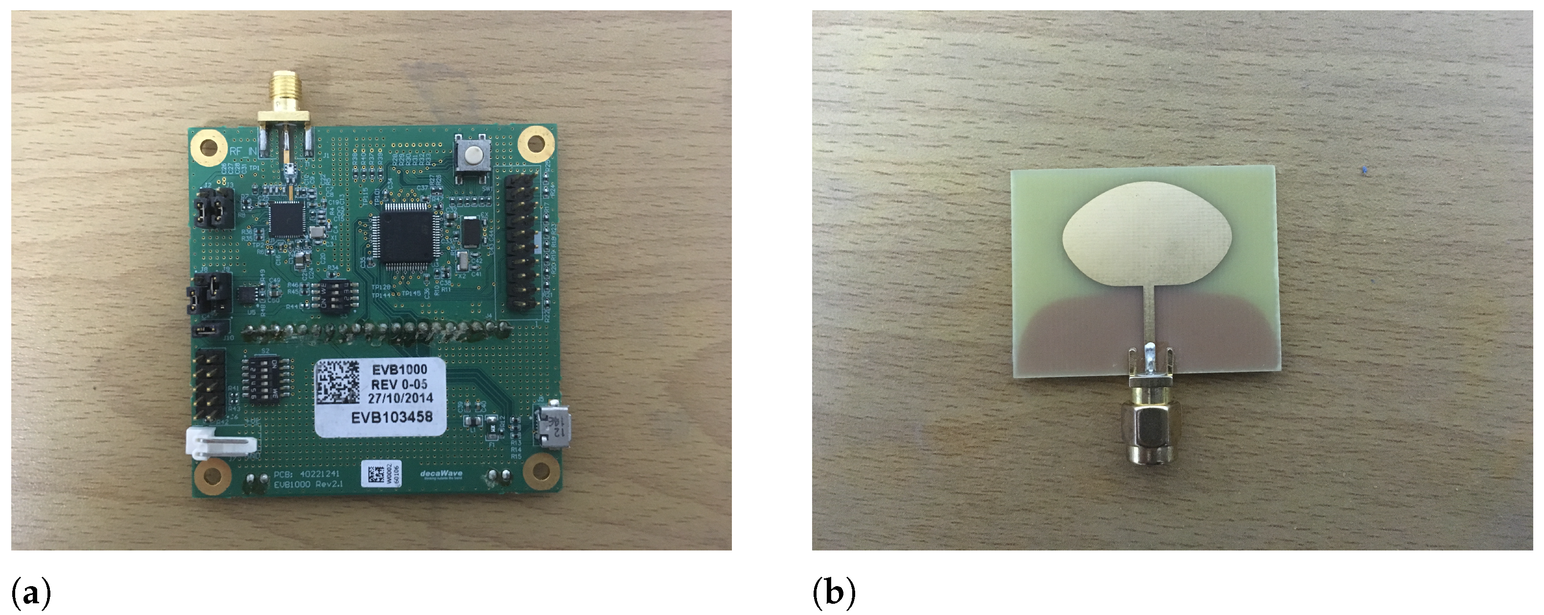
The wireless sensors used in the experiments are EVB1000 development boards manufactured by Decawave, showed in Figure 3. The development board features a low-power, low-cost RF module DW1000 and an ARM Cortex-M3 micro-controller. The DW1000 is a fully integrated radio transceiver compliant with the IEEE 802.15.4 ultra-wideband (UWB) standard, providing a comprehensive solution for the UWB sensing technology [49]. The chip is set to have a maximum transmit power allowed by spectral emission regulations ( 41.3 dBm/MHz). The radio spans 6 RF bands ranging from 3.5 GHz to 6.5 GHz and supports data rates of 110 kbps, 850 kbps and 6.8 Mbps. The node is equipped with an ultra-wideband omni-directional planar monopole antenna [50] specifically designed for DW1000 with the maximum gain 3.3 dBi at 6.5 GHz.

6.2. Communication Protocol

In our previous work [35], we developed a multi-sensor communication protocol, multi-Ranging, to support multi-sensor ranging and sensor self-localization and acquisition of the received power level of each link. Since the ranging process is time-consuming, it is limited to stationary target positioning. In this paper, we develop a token passing protocol on the EVB1000 to allow real-time fast human tracking for our UWB-based RTI system. In the protocol, each node takes turns to transmit the packet based on the hard-coded node ID to avoid packet collision. At any instant, there is only one transmitting node and the others receive the packet from it. The MAC payload of the packet consists of the transmitting node ID and the latest RSS measurements (in total or the first path) from the other nodes. Another node serves as the base station to hear all the packets over the air and feed them to a laptop via a USB port.

6.3. RF Configuration

Although a total of 8 RF channel configurations are recommended in the DW1000 module, channel mode 5 listed in Table 1 is used as it is calibrated for the transmitted power and antenna delay during the production [51]. Note that in this mode, the pulse signal is transmitted at a center frequency of 6.4896 GHz and occupies a relatively wide bandwidth of 499.2 MHz.
According to Table 1, we can accurately estimate the successive packet duration in our communication protocol so as to guarantee the tracking speed and determine the time step for trajectory filters. Suppose that the number of measurement sensors is N; since the power level allowing 0.1-dB precision is 2 bytes long, the length of the MAC payload is 2 N 1 bytes, containing the node ID (1-byte) and RSS measurements ( 2 ( N 1 ) -byte). Including a 9-byte MAC header using 16-bit address and a 2-byte checksum, the total length of the physical packet payload is 2 N + 10 bytes.
The physical packet can be divided into a synchronization header (SHR), physical layer header (PHR) and data unit (DATA). From the above analysis, it can be seen that the length of DATA is N DATA = 2 N + 10 bytes. When PRF is 16 MHz, the SHR symbol consists of 496 pulses, resulting in
T SHRsymbol = 496 × T b 993.59 ns ,
since SHR contains a preamble length of 1024 and SFD length of 64, the duration of SHR is
T SHR = ( 1024 + 64 ) × T SHRsymbol 1.08 ms .
A hybrid modulation based on burst position modulation (BPM) and binary phase shift keying (BPSK) is used for the PHR and DATA. When the data rate is 110 kbps , the BPM-BPSK symbol includes 32 burst positions and each has 128 pulses, resulting in 4096 pulses in total. The duration of the BPM-BPSK symbol is
T BPM - BPSKsymbol = 4096 × T b 8205.13 ns .
In the encoding process of the physical layer, DATA is first encoded by RS(63,55) (Reed-Solomon), followed by convolutional encoding together with the 19-bit PHR, and it is finally mapped to BPM-BPSK symbols after 2 tail bits are added. When the rate of the convolutional encoding is 0.5, there are 21 symbols in PHR and the number of symbols in DATA is the same as the number of bits after RS encoding. As a result, the duration of PHR and DATA can be calculated as
T PHR = 21 × T BPM - BPSKsymbol 0.17 ms ,
T DATA = 8 N DATA + 8 N DATA / 330 × 48 × T BPM - BPSKsymbol ,
and the duration of the physical packet can be finally given by
T = T SHR + T PHR + T DATA .
Equation (26) provides a theoretical reference for packet duration estimation. It is helpful to verify the stability and scalability of our UWB networks for real-time tracking. In practical tests of N = 16 , a total average number of 3936 packets received during 20 s results in a duration of 5.08 ms per packet, which is basically consistent with the theoretical calculation value 4.79 ms, allowing for packet loss and processing time. Since the packet interval is at the millisecond level, the sampling rate is high enough to track fast-moving targets. If a higher sampling rate is required for faster target movement, the data rate needs to be increased. Specifically, the packet duration in N = 16 networks will be theoretically reduced to be 1.54 ms and 1.16 ms for the data rate of 850 kbps and 6.8 Mbps in respective order. Since the data rate is increased at the expense of communication distance, trade-offs should be balanced between the sampling resolution and network coverage.
As pointed in [49], for 16 MHz PRF, the received power level can be accurately calculated compared to the actual power at lower levels, i.e., <−85 dBm. Fortunately, such a measurement requirement can be easily satisfied for various application scenarios with tunable power gain, which can be set to 0 dB for an outdoor open space and 6 dB for typical indoor office environments according to our practical experience.

6.4. Field Experiments

We conduct extensive field tests in 2 different environments in which dozens of 802.11 a/b/g/n wireless networks exist, increasing interference with our network. Sixteen sensors are placed on pillars at a height of 0.9 m above the ground to cut down the reflection noise. Narrowband RTI uses the TI CC2530 2.4 GHz half-duplex transceiver with an omni-directional antenna and a maximum transmit power of 4.5 dBm. The communication protocol used for channel diversity is similar to that in [10] with a channel list { 11 , 15 , 18 , 21 , 26 } . For the tracking, a walker following the rhythm of a metronome is asked to walk along pre-defined trajectories.
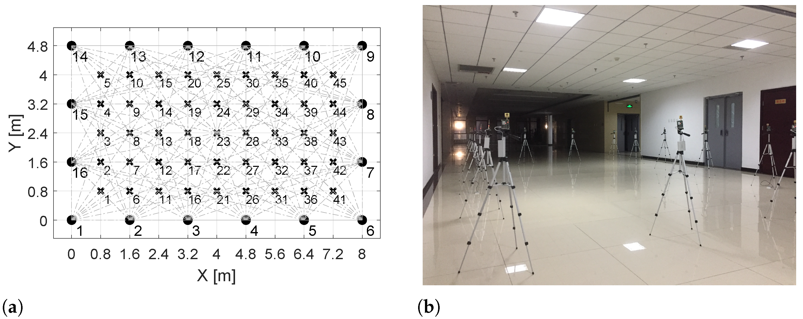
Experiment 1 is conducted in a relatively open corridor with an area of 8 m × 4.8 m = 38.4 m 2 . As shown in Figure 4a, 45 test points are specified in the monitored area for localization. A walker moves along the pre-defined trajectory at a constant speed of 0.4 m / 0.75 s 0.53 m / s .
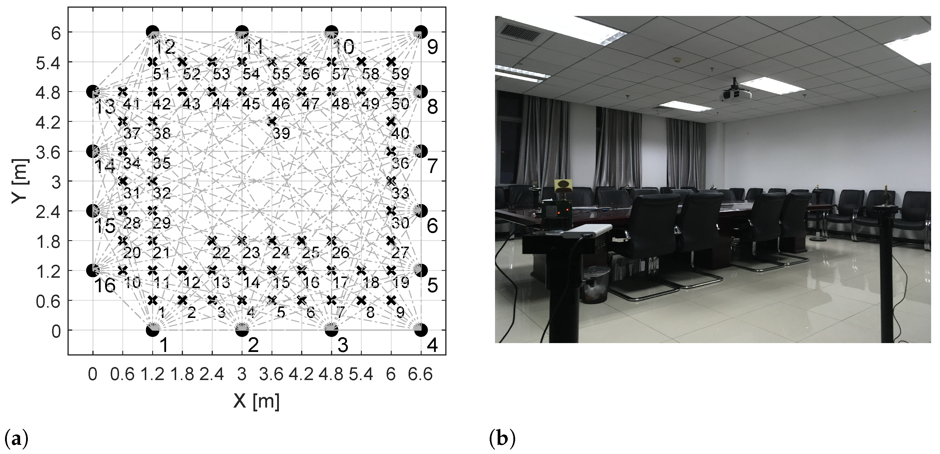
The scenario of experiment 2 is a 6.6 m × 6 m = 39.6 m 2 conference room containing tables, chairs and other obstacles, which can be considered as a cluttered indoor environment. We select 59 available test locations in the area shown in Figure 5a. The walker moves along the specified trajectory with a constant velocity of 0.6 m / 0.75 s = 0.8 m / s .

7. Performance Evaluation

This section evaluates the performance of our proposed UWB-based RTI through real experimental data and compares it with multi-channel narrowband RTI (CD-NRTI for short). For simplicity, UWB-based RTI based on the total path and the LoS path are denoted as UWB-RTI and LoS-RTI, respectively. In CD-NRTI, we sort the channels in the channel list based on the fading level and select m = 3 channels with the smallest fading for each link l to build the available channel list D l , m . The link RSS attenuation is then averaged over D l , m , namely Δ R l = 1 m c D l , m Δ R l , c . We roughly estimate that the average time duration of the successive packet in CD-NRTI is 1.95 ms , and thus, the RSS measurement update time is 16 × 5 × 1.95 = 156 ms . The parameters used in the evaluation are summarized in Table 2. Several rounds of RSS measurements are averaged for the tracking evaluation on account of packet loss.
We use the root-mean-square error (RMSE) and empirical cumulative distribution function (eCDF) to qualitatively assess the localization and tracking performance.

7.1. Results of Experiment 1

The localization results in experiment 1 are illustrated in Figure 6. As can be seen, the three RTI methods are able to effectively locate the target because there are fewer interference materials in the environment. However, the localization accuracy of UWB-RTI and LoS-RTI is between than that of CD-NRTI. To be specific, the localization error of CD-NRTI is greater than 0.25 m at some spots (position 3 and 14), while that of UWB-RTI and LoS-RTI is both below 0.15 m . As shown in Table 3, in terms of the RMSE, the location accuracy of UWB-based RTI is improved by 25 % compared to CD-NRTI, and the localization performance of UWB-RTI is basically the same as LoS-RTI.
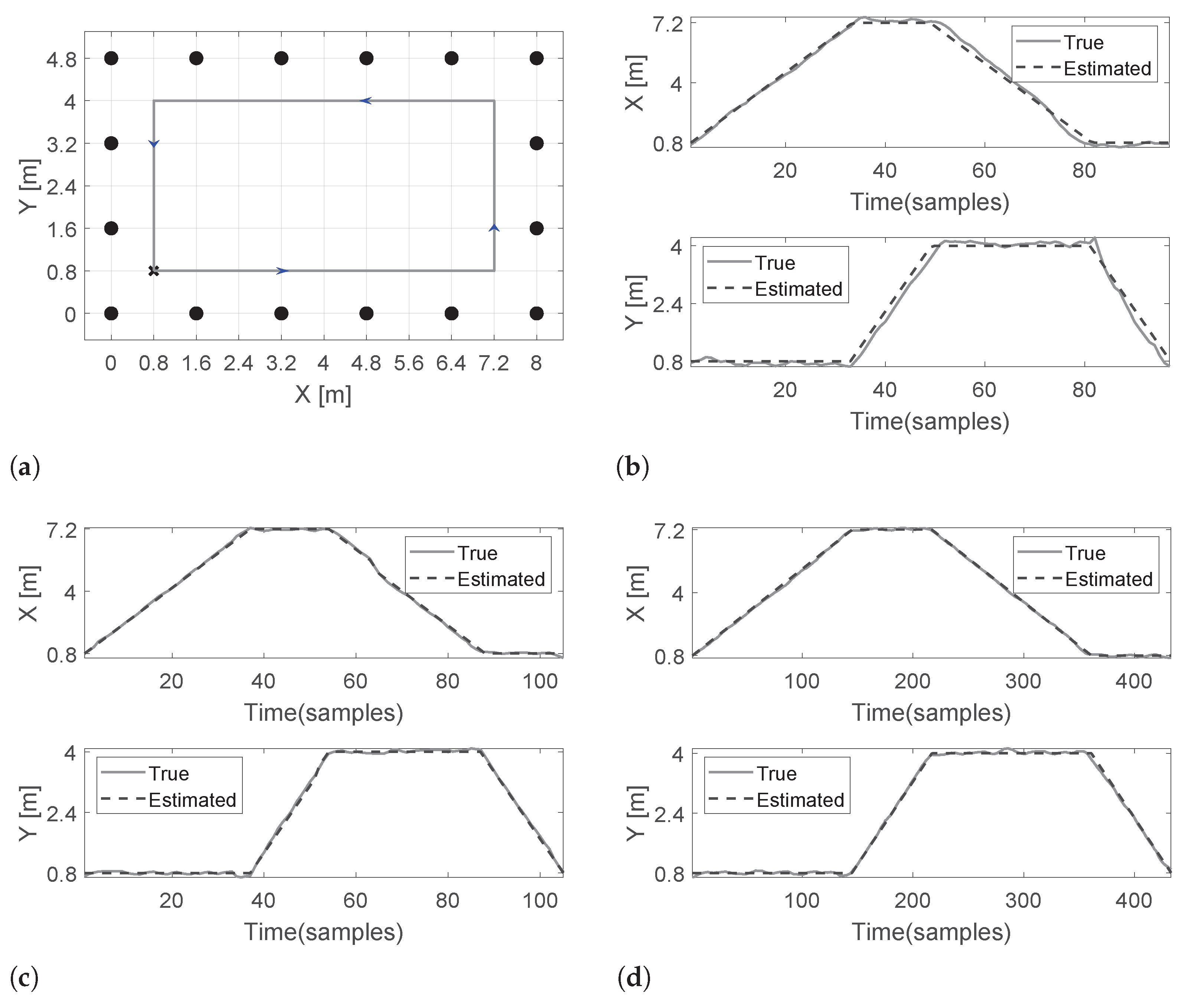
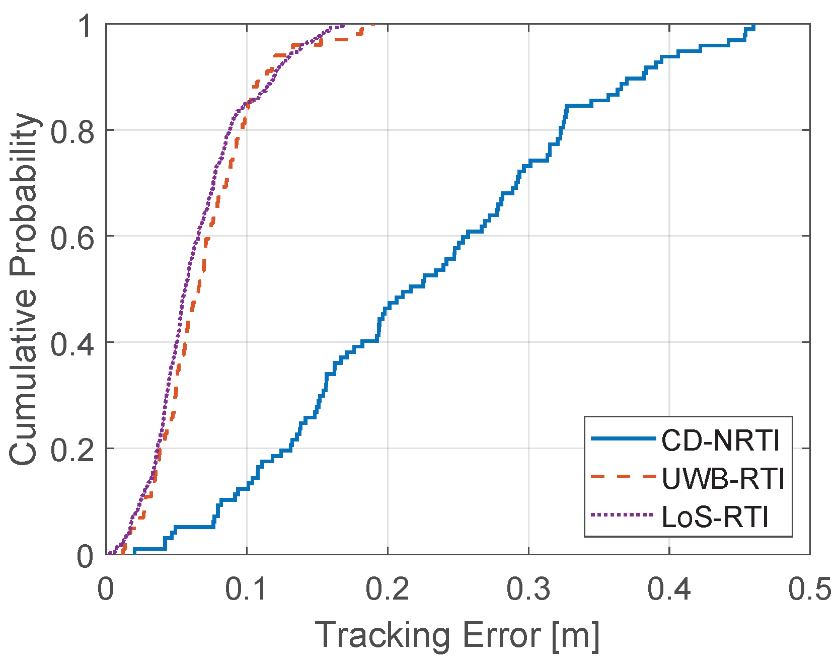
Figure 7 shows the tracking results of experiment 1. CD-NRTI deviates greatly from the path during tracking with an RMSE of 0.25 m . On the contrary, the estimated path of UWB-based RTI agrees well with the real path. The tracking accuracy is improved by 68 % compared to CD-NRTI. Moreover, LoS-RTI is slightly better than UWB-RTI. Figure 8 plots the eCDF of tracking errors. At a 90 percentage level, the tracking error of CD-NRTI, UWB-RTI, and LoS-RTI are estimated to be no more than 0.38 m , 0.11 m , and 0.12 m , respectively.

7.2. Results of Experiment 2

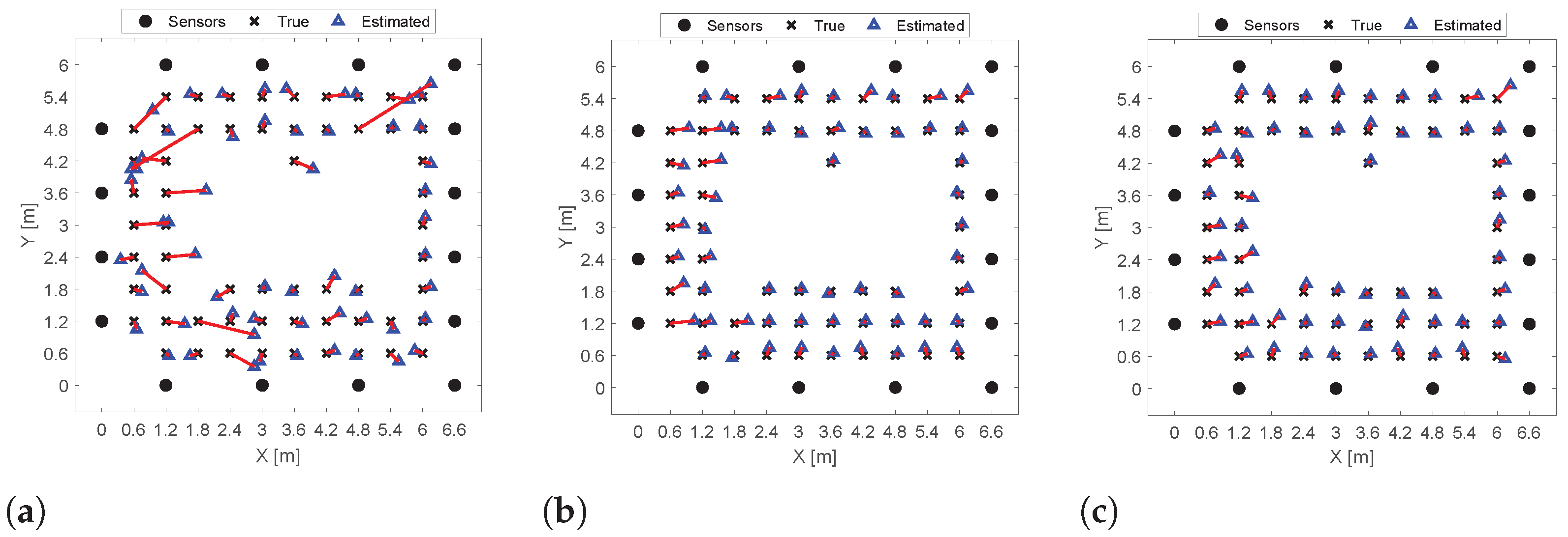
Contrary to experiment 1 with less multipath interference, the rich multipath in experiment 2 greatly reduces the accuracy of target localization and tracking. Compared to Table 3, the RMSE of CD-NRTI and UWB-based RTI reported in Table 4 deteriorates by 217 % and 71 % for localization, demonstrating that narrowband RTI is more sensitive to interference, while wideband RTI is more anti-interference. Figure 9 shows that for CD-NRTI, 13 % of test locations have an error of more than 0.5 m . However, there are no significant deviations for UWB-based RTI. The localization accuracy of UWB-based RTI is improved by 59 % compared to that of CD-NRTI in the indoor cluttered environment.
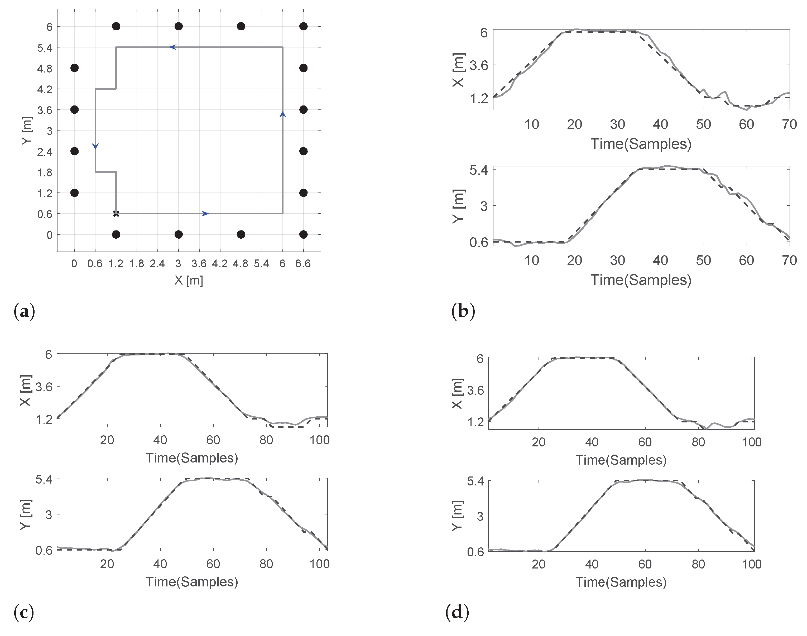
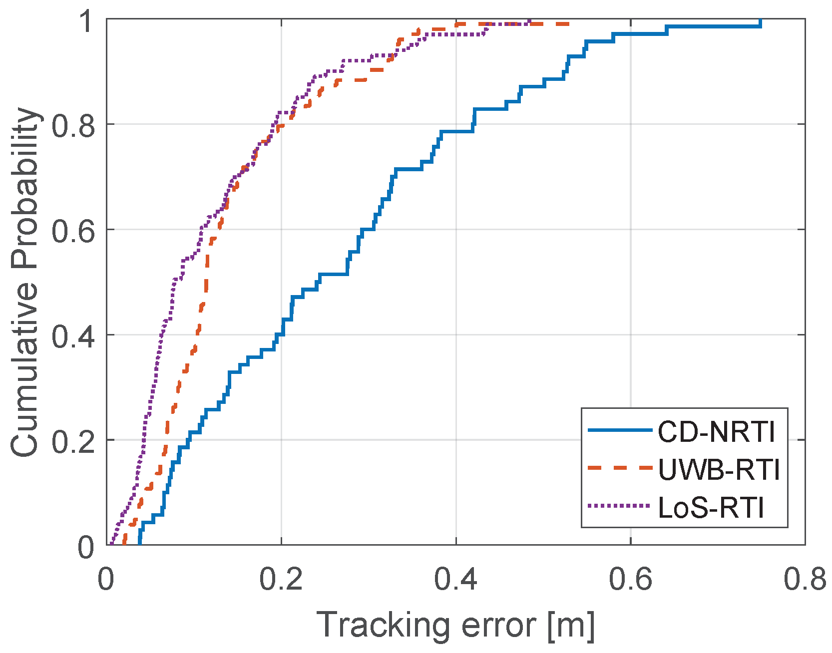
Figure 10 depicts the tracking results in experiment 2. Multipath interference caused by reflections from dense obstructions leads to the poor tracking accuracy of CD-NRTI, especially when the target’s motion state changes frequently within a short time. However, the estimated path using UWB-based RTI is basically in agreement with the real path with an accuracy of 0.16 m , improved by 46 % compared to that of CD-NRTI. The eCDF of tracking errors plotted in Figure 11 shows that the localization error at a 90 percentage level is no more than 0.52 m with CD-NRTI, 0.3 m with UWB-RTI, and 0.25 m with LoS-RTI.

8. Discussion

This study focuses solely on a single-target localization and tracking scenario. However, in practical localization environments, multiple targets are often present, and their number may vary over time. The challenges of applying the system to multi-target scenarios mainly involve multi-target attenuation measurement modeling, multi-target association, and filtering. The impact of multiple targets on signal propagation is so highly complex that resulting variations in RSS cannot be simply regarded as the linear superposition of individual target effects, but rather as mutual coupling among targets. Several multi-target attenuation statistical models have already been developed either through extensive experimental fitting or based on diffraction theory. Although the accuracy is considered acceptable, it can still be further improved. With the help of CIR measurements from UWB, we can expect to establish more accurate multi-target models by leveraging multipath-enhanced methods. Another important issue deserving of investigation is over-clustering and false detection in target association, which can be mitigated through a combination of data association (e.g., a joint probabilistic data association filter, multiple hypothesis tracking) and filtering methods (e.g., multiple particle filtering, Markov Chain Monte Carlo filtering) or even more computationally demanding approaches such as a probability hypothesis density filter based on a random finite set.

9. Conclusions

This paper presents a real-time UWB-based DFLT system. The impact of multipath effects on target-induced RSS variations is analyzed for both narrowband and wideband signals, showing that UWB RSS measurements enable a more reliable estimation of shadowing loss. Two types of UWB RSS measurements are proposed—one based on the total received signal and the other on the line-of-sight path—with the latter demonstrating greater robustness to multipath interference. An efficient measurement protocol for UWB networks is also developed for real-time tracking. Performance comparisons conducted in indoor and outdoor scenarios confirm the effectiveness of the proposed UWB-based DFLT system.

Author Contributions

Conceptualization, S.X. and H.L.; methodology, S.X. and H.L.; software, S.X.; validation, S.X.; formal analysis, S.X.; investigation, S.X.; resources, S.X.; data curation, S.X.; writing—original draft preparation, S.X.; writing—review and editing, S.X. and H.L.; visualization, S.X.; supervision, D.L., Z.Z. and H.L.; project administration, D.L., Z.Z. and H.L.; funding acquisition, H.L. All authors have read and agreed to the published version of the manuscript.

Funding

This research was funded by the National Key R&D Program of China (Grant No. 2022YFC3301201).

Institutional Review Board Statement

Not applicable.

Informed Consent Statement

Not applicable.

Data Availability Statement

The data are available from the authors upon reasonable request.

Conflicts of Interest

The authors declare no conflicts of interest.

References

  1. Bi, J.; Wang, J.; Cao, H.; Yao, G.; Wang, Y.; Li, Z.; Sun, M.; Yang, H.; Zhen, J.; Zheng, G. Inverse distance weight-assisted particle swarm optimized indoor localization. Appl. Soft Comput. 2024, 164, 112032. [Google Scholar] [CrossRef]
  2. Luoh, L. ZigBee-based intelligent indoor positioning system soft computing. Soft Comput. 2014, 18, 443–456. [Google Scholar] [CrossRef]
  3. Tan, P.; Tsinakwadi, T.H.; Xu, Z.; Xu, H. Sing-Ant: RFID indoor positioning system using single antenna with multiple beams based on LANDMARC algorithm. Appl. Sci. 2022, 12, 6751. [Google Scholar] [CrossRef]
  4. Azaddel, M.H.; Nourian, M.A.; Shahhosseini, K.; Junoh, S.A.; Akbari, A. SPOTTER: A novel asynchronous and independent WiFi and BLE fusion method based on particle filter for indoor positioning. Internet Things 2023, 24, 100967. [Google Scholar] [CrossRef]
  5. Mager, B.; Lundrigan, P.; Patwari, N. Fingerprint-based device-free localization performance in changing environments. IEEE J. Sel. Areas Commun. 2015, 33, 2429–2438. [Google Scholar] [CrossRef]
  6. Wilson, J.; Patwari, N. Radio tomographic imaging with wireless networks. IEEE Trans. Mob. Comput. 2010, 9, 621–632. [Google Scholar] [CrossRef]
  7. Savazzi, S.; Nicoli, M.; Carminati, F.; Riva, M. A Bayesian approach to device-free localization: Modeling and experimental assessment. IEEE J. Sel. Top. Signal Process. 2014, 8, 16–29. [Google Scholar] [CrossRef]
  8. Kaltiokallio, O.; Yiğitler, H.; Jäntti, R. A three-state received signal strength model for device-free localization. IEEE Trans. Veh. Technol. 2017, 66, 9226–9240. [Google Scholar] [CrossRef]
  9. Wang, Z.; Liu, H.; Xu, S.; Bu, X.; An, J. A diffraction measurement model and particle filter tracking method for RSS-based DFL. IEEE J. Sel. Areas Commun. 2015, 33, 2391–2403. [Google Scholar] [CrossRef]
  10. Kaltiokallio, O.; Bocca, M.; Patwari, N. Enhancing the accuracy of radio tomographic imaging using channel diversity. In Proceedings of the 2012 IEEE 9th International Conference on Mobile Ad-Hoc and Sensor Systems (MASS 2012), Las Vegas, NV, USA, 8–11 October 2012; IEEE: Piscataway, NJ, USA, 2012; pp. 254–262. [Google Scholar]
  11. Wang, M.; Wang, Z.; Ding, E.; Yang, Y. Dual-band sensor network for accurate device-free localization in indoor environment with wifi interference. IEICE Trans. Inf. Syst. 2015, 98, 596–606. [Google Scholar] [CrossRef]
  12. Fink, A.; Ritt, T.; Beikirch, H. Redundant radio tomographic imaging for privacy-aware indoor user localization. In Proceedings of the 2015 International Conference on Indoor Positioning and Indoor Navigation (IPIN), Banff, AB, Canada, 13–16 October 2015; IEEE: Piscataway, NJ, USA, 2015; pp. 1–7. [Google Scholar]
  13. Denis, S.; Berkvens, R.; Ergeerts, G.; Bellekens, B.; Weyn, M. Combining multiple sub-1 ghz frequencies in radio tomographic imaging. In Proceedings of the 2016 International Conference on Indoor Positioning and Indoor Navigation (IPIN), Madrid, Spain, 4–7 October 2016; IEEE: Piscataway, NJ, USA, 2016; pp. 1–8. [Google Scholar]
  14. Denis, S.; Berkvens, R.; Ergeerts, G.; Weyn, M. Multi-frequency sub-1 GHz radio tomographic imaging in a complex indoor environment. In Proceedings of the 2017 International Conference on Indoor Positioning and Indoor Navigation (IPIN), Sapporo, Japan, 18–21 September 2017; IEEE: Piscataway, NJ, USA, 2017; pp. 1–8. [Google Scholar]
  15. Bocca, M.; Luong, A.; Patwari, N.; Schmid, T. Dial it in: Rotating RF sensors to enhance radio tomography. In Proceedings of the 2014 Eleventh Annual IEEE International Conference on Sensing, Communication, and Networking (SECON), Singapore, 30 June–3 July 2014; IEEE: Piscataway, NJ, USA, 2014; pp. 600–608. [Google Scholar]
  16. Xu, S.; Liu, H.; Gao, F.; Wang, Z. Compressive sensing based radio tomographic imaging with spatial diversity. Sensors 2019, 19, 439. [Google Scholar] [CrossRef]
  17. Wei, B.; Varshney, A.; Patwari, N.; Hu, W.; Voigt, T.; Chou, C.T. dRTI: Directional Radio Tomographic Imaging. In Proceedings of the 14th International Conference on Information Processing in Sensor Networks, New York, NY, USA, 13–16 April 2015; IPSN ’15. pp. 166–177. [Google Scholar]
  18. Qi, C.; Hillyard, P.; Al-Husseiny, A.; Patwari, N.; Durgin, G.D. On-Wall, Wide Bandwidth E-Shaped Patch Antenna for Improved Whole-Home Radio Tomography. IEEE J. Radio Freq. Identif. 2017, 1, 22–31. [Google Scholar] [CrossRef]
  19. Wang, Z.; Liu, H.; Ma, X.; An, J.; Xu, S. Enhancing indoor radio tomographic imaging based on interference link elimination. Digit. Signal Process. 2015, 44, 26–36. [Google Scholar] [CrossRef]
  20. Kaltiokallio, O.; Jäntti, R.; Patwari, N. ARTI: An adaptive radio tomographic imaging system. IEEE Trans. Veh. Technol. 2017, 66, 7302–7316. [Google Scholar] [CrossRef]
  21. Yiğitler, H.; Jäntti, R.; Kaltiokallio, O.; Patwari, N. Detector based radio tomographic imaging. IEEE Trans. Mob. Comput. 2018, 17, 58–71. [Google Scholar] [CrossRef]
  22. Patwari, N.; Agrawal, P. Effects of correlated shadowing: Connectivity, localization, and RF tomography. In Proceedings of the 2008 International Conference on Information Processing in Sensor Networks (IPSN 2008), St. Louis, MO, USA, 22–24 April 2008; IEEE: Piscataway, NJ, USA, 2008; pp. 82–93. [Google Scholar]
  23. Patra, A.; Simic, L.; Petrova, M. mmRTI: Radio tomographic imaging using highly-directional millimeter-wave devices for accurate and robust indoor localization. In Proceedings of the 2017 IEEE 28th Annual International Symposium on Personal, Indoor, and Mobile Radio Communications (PIMRC), Montreal, QC, Canada, 8–13 October 2017; IEEE: Piscataway, NJ, USA, 2017; pp. 1–7. [Google Scholar]
  24. Li, Y.; Chen, X.; Coates, M.; Yang, B. Sequential Monte Carlo radio-frequency tomographic tracking. In Proceedings of the 2011 IEEE International Conference Acoustics, Speech and Signal Processing (ICASSP), Prague, Czech Republic, 22–27 May 2011; IEEE: Piscataway, NJ, USA, 2011; pp. 3976–3979. [Google Scholar]
  25. Nannuru, S.; Li, Y.; Zeng, Y.; Coates, M.; Yang, B. Radio-frequency tomography for passive indoor multitarget tracking. IEEE Trans. Mob. Comput. 2012, 12, 2322–2333. [Google Scholar] [CrossRef]
  26. Guo, Y.; Huang, K.; Jiang, N.; Guo, X.; Li, Y.; Wang, G. An exponential-Rayleigh model for RSS-based device-free localization and tracking. IEEE Trans. Mob. Comput. 2015, 14, 484–494. [Google Scholar] [CrossRef]
  27. Savazzi, S.; Sigg, S.; Nicoli, M.; Rampa, V.; Kianoush, S.; Spagnolini, U. Device-free radio vision for assisted living: Leveraging wireless channel quality information for human sensing. IEEE Signal Process. Mag. 2016, 33, 45–58. [Google Scholar] [CrossRef]
  28. Rampa, V.; Savazzi, S.; Nicoli, M.; D’Amico, M. Physical modeling and performance bounds for device-free localization systems. IEEE Signal Process. Lett. 2015, 22, 1864–1868. [Google Scholar] [CrossRef]
  29. Nicoli, M.; Rampa, V.; Savazzi, S.; Schiaroli, S. Device-free localization of multiple targets. In Proceedings of the 2016 24th European Signal Processing Conference (EUSIPCO), Budapest, Hungary, 29 August–2 September 2016; IEEE: Piscataway, NJ, USA, 2016; pp. 738–742. [Google Scholar]
  30. Wang, J.; Gao, Q.; Pan, M.; Zhang, X.; Yu, Y.; Wang, H. Toward accurate device-free wireless localization with a saddle surface model. IEEE Trans. Veh. Technol. 2015, 65, 6665–6677. [Google Scholar] [CrossRef]
  31. Wu, H.; Ma, X.; Yang, C.H.H.; Liu, S. Convolutional neural network based radio tomographic imaging. In Proceedings of the 2020 54th Annual Conference on Information Sciences and Systems (CISS), Princeton, NJ, USA, 18–20 March 2020; IEEE: Piscataway, NJ, USA, 2020; pp. 1–6. [Google Scholar]
  32. Wu, H.; Cheng, C.; Peng, T.; Zhou, H.; Chen, T. Combining transformer with a latent variable model for radio tomography based robust device-free localization. Comput. Commun. 2025, 231, 108022. [Google Scholar] [CrossRef]
  33. Lu, Z.; Liu, H.; Zhang, X. Radio tomographic imaging localization based on transformer model. In Proceedings of the 2023 IEEE 6th Information Technology, Networking, Electronic and Automation Control Conference (ITNEC), Chongqing, China, 24–26 February 2023; IEEE: Piscataway, NJ, USA, 2023; Volume 6, pp. 1134–1138. [Google Scholar]
  34. Cheraghinia, M.; Shahid, A.; Luchie, S.; Gordebeke, G.J.; Caytan, O.; Fontaine, J.; Van Herbruggen, B.; Lemey, S.; De Poorter, E. A comprehensive overview on UWB radar: Applications, standards, signal processing techniques, datasets, radio chips, trends and future research directions. IEEE Commun. Surv. Tutor. 2024, 27, 2283–2324. [Google Scholar] [CrossRef]
  35. Wang, Z.; Liu, H.; Xu, S.; Gao, F.; Bu, X.; An, J. Towards robust and efficient device-free localization using UWB sensor network. Pervasive Mob. Comput. 2017, 41, 451–469. [Google Scholar] [CrossRef]
  36. Yang, J.; Wang, M.; Yang, Y.; Wang, J. A device-free localization and size prediction system for road vehicle surveillance via UWB networks. IEEE Trans. Instrum. Meas. 2021, 71, 1–11. [Google Scholar] [CrossRef]
  37. Wang, J.; Yang, J.; Wang, M. Device-free localization and tracking of multiple person in UWB sensor networks. In Proceedings of the 2021 International Conference on Sensing, Measurement & Data Analytics in the era of Artificial Intelligence (ICSMD), Nanjing, China, 21–23 October 2021; IEEE: Piscataway, NJ, USA, 2021; pp. 1–7. [Google Scholar]
  38. Schmidhammer, M.; Gentner, C.; Sand, S.; Fiebig, U.C. Multipath-enhanced device-free localization in wideband wireless networks. IEEE Antennas Wirel. Propag. Lett. 2021, 20, 453–457. [Google Scholar] [CrossRef]
  39. Schmidhammer, M.; Gentner, C. Multipath-enhanced device-free localization using low-cost ultra-wideband devices. In Proceedings of the 2022 16th European Conference on Antennas and Propagation (EuCAP), Madrid, Spain, 27 March–1 April 2022; IEEE: Piscataway, NJ, USA, 2022; pp. 1–5. [Google Scholar]
  40. Cimdins, M.; Schmidt, S.O.; John, F.; Constapel, M.; Hellbrück, H. MA-RTI: Design and Evaluation of a Real-World Multipath-Assisted Device-Free Localization System. Sensors 2023, 23, 2199. [Google Scholar] [CrossRef] [PubMed]
  41. Gao, Y.; Xu, H.; Li, C.; Wang, Y.; Shi, Z. Passive human sensing based on UWB CIR. In Proceedings of the 2024 IEEE/CIC International Conference on Communications in China (ICCC), Hangzhou, China, 7–9 August 2024; IEEE: Piscataway, NJ, USA, 2024; pp. 1680–1685. [Google Scholar]
  42. Yang, S.; Xiao, X.; Wang, X.; Chen, Z.; Sheng, M.; Yao, Z. Multipath Components Modeling and Measuring in Device-Free Underground Parking Localization. In Proceedings of the 2024 IEEE/CIC International Conference on Communications in China (ICCC), Hangzhou, China, 7–9 August 2024; IEEE: Piscataway, NJ, USA, 2024; pp. 417–422. [Google Scholar]
  43. Lee, H.S. Device-Free Localization Using Commercial UWB Transceivers. arXiv 2025, arXiv:2507.13938. [Google Scholar] [CrossRef]
  44. Poeggel, R.; Stahlke, M.; Pirkl, J.; Ott, J.; Yammine, G.; Feigl, T.; Mutschler, C. Passive Channel Charting: Locating Passive Targets using a UWB Mesh. arXiv 2025, arXiv:2505.10194. [Google Scholar] [CrossRef]
  45. Maas, D.; Firooz, M.H.; Zhang, J.; Patwari, N.; Kasera, S.K. Channel sounding for the masses: Low complexity gnu 802.11 b channel impulse response estimation. IEEE Trans. Wirel. Commun. 2012, 11, 1–8. [Google Scholar] [CrossRef]
  46. Texas Instruments. CC253x/4x User’s Guide. 2014. Available online: http://www.ti.com/lit/ug/swru191f/swru191f.pdf (accessed on 23 August 2015).
  47. Wilson, J.; Patwari, N. A fade-level skew-laplace signal strength model for device-free localization with wireless networks. IEEE Trans. Mob. Comput. 2012, 11, 947–958. [Google Scholar] [CrossRef]
  48. Hillyard, P.; Maas, D.; Premnath, S.; Patwari, N.; Kasera, S. Through-wall person localization using transceivers in motion. arXiv 2015, arXiv:1511.06703. [Google Scholar] [CrossRef]
  49. Decawave (Qorvo). DW1000 User Manual. 2017. Available online: https://www.qorvo.com/products/d/da007967 (accessed on 23 August 2025).
  50. Decawave (Qorvo). Decawave Reference Planar Monopole Antenna. 2014. Available online: https://www.decawave.com/uwb-antennae-design-files/ (accessed on 23 August 2025).
  51. Decawave (Qorvo). Decawave EVK1000 User Manual. 2016. Available online: https://www.qorvo.com/products/d/da007993 (accessed on 10 July 2025).
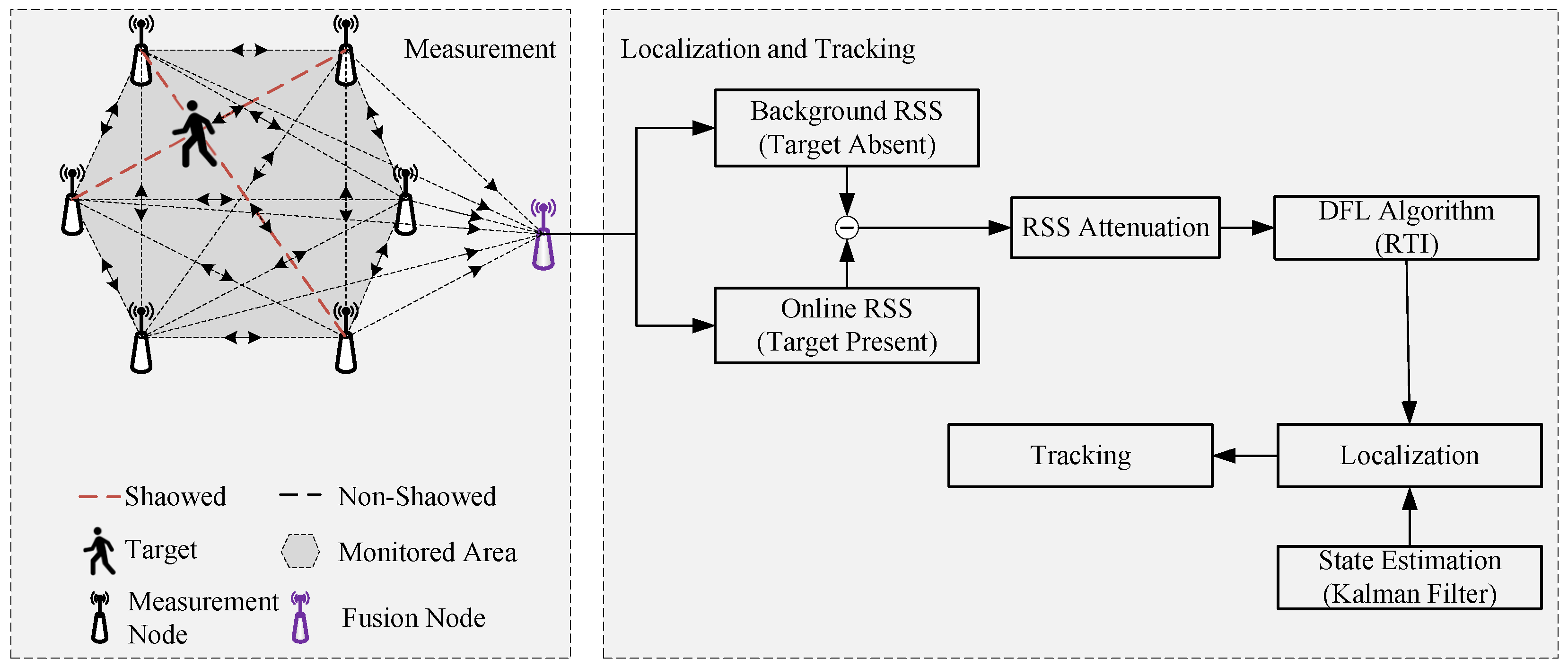
Figure 1. System overview of our proposed UWB-based DFTL system.
Electronics 14 03362 g001
Figure 2. The field test using narrowband and wideband transceivers. (a) The experimental layout. (b) RSS attenuations captured from the experiment. (ce) are reconstructed images with a narrowband ( Δ R n b ), wideband ( Δ R w b ) and first path ( Δ R l o s ), respectively. The true and estimated positions are represented with point ’•’ and a plus sign, ’+’, in attenuation images, respectively.
Electronics 14 03362 g002
Figure 3. Decawave EVB1000 development board with (a) ScenSor DW1000 UWB RF module and (b) omni-directional planar monopole antenna.
Electronics 14 03362 g003
Figure 4. Experiment 1: corridor—(a) layout and (b) photography.
Electronics 14 03362 g004
Figure 5. Experiment 2: conference room—(a) layout and (b) photography.
Electronics 14 03362 g005
Figure 6. Localization results of experiment 1 with (a) CD-NRTI, (b) UWB-RTI and (c) LoS-RTI.
Electronics 14 03362 g006
Figure 7. Tracking results of (a) the real path in experiment 1 with (b) CD-NRTI, (c) UWB-RTI and (d) LoS-RTI.
Electronics 14 03362 g007
Figure 8. eCDF of tracking errors of experiment 1.
Electronics 14 03362 g008
Figure 9. Localization results of experiment 2 with (a) CD-NRTI, (b) UWB-RTI and (c) LoS-RTI.
Electronics 14 03362 g009
Figure 10. Tracking results of (a) the real path in experiment 2 with (b) CD-NRTI, (c) UWB-RTI and (d) LoS-RTI.
Electronics 14 03362 g010
Figure 11. eCDF of tracking errors of experiment 2.
Electronics 14 03362 g011
Table 1. The used channel configuration.
ModeChannelCenter Frequency [GHz]Bandwidth [MHz]Data Rate [kbps]PRF * [MHz]Preamble LengthPreamble CodeNs-SFD †
55 6.4896 499.2 1101610243Yes
* Preamble reception frequency. † Non-standard start of frame delimiter.
Table 2. Evaluation parameters.
ParameterValueDescription
δ 0.1 grid size [m]
Δ 0.0625 (narrowband)maximum extra path length [m]
0.023 (UWB)
μ 100regularization parameter
d c 2correlation distance [m]
σ w 2 0.4 movement noise variance [ ( m / s 2 ) 2 ]
σ v 2 0.1 measurement noise variance [ m 2 ]
Table 3. RMSE of localization and tracking in experiment 1 [m].
CD-NRTIUWB-RTILoS-RTI
Localization 0.1287 0.0972 0.0901
Tracking 0.2507 0.0816 0.0729
Table 4. RMSE of localization and tracking in experiment 2 [m].
CD-NRTIUWB-RTILoS-RTI
Localization 0.4091 0.1665 0.1527
Tracking 0.3142 0.1692 0.1586
Disclaimer/Publisher’s Note: The statements, opinions and data contained in all publications are solely those of the individual author(s) and contributor(s) and not of MDPI and/or the editor(s). MDPI and/or the editor(s) disclaim responsibility for any injury to people or property resulting from any ideas, methods, instructions or products referred to in the content.