Abstract
Modern networked industrial applications often require low-latency communication. Some applications evolve over time, however, are tied to yet existing infrastructures, like power grids spanning across large areas. For instance, medium voltage direct current (MVDC) grids are evolving to a promising alternative to traditional medium voltage alternating current (MVAC) grids due to their efficiency and suitability for novel use cases like electric mobility. MVDC grids, however, require an active control and fault handling strategy. Some strategies demand for a continuous state exchange of the converter substations via a low-latency communication channel with less than 1 millisecond. While some communication approaches for MVDC grids are described in the literature, none of them is inherently designed to be secure. In this paper, we present a protocol for ultra-low-latency secure state exchange (PULLSE) based on conventional non-deterministic Ethernet and AES-GCM. We chose Ethernet in order to not limit the approaches usability in terms of hardware requirements or communication patterns. PULLSE is designed to prevent traffic eavesdropping, replay, and manipulation attacks.
1. Introduction
Many modern industrial applications demand for communication systems with very low latency. For these kinds of applications, research and the industry have developed various approaches for deterministic data transmission, which allows a “predictable and stable transmission of control parameters between the devices attached to the network” [1]. They are often based on commercial Ethernet, which, by design, cannot assure determinism because of medium access control mechanisms (CSMA/CD), packet buffering in network devices or unpredictable traffic load conditions [2]. Deterministic networking solutions like Ethernet TSN, Ethercat or ProfiNet, however, require specialized hardware, conditions, and dictated network device role models and sometimes come along with reliance on single manufacturers. Using commercial-off-the-shelf (COTS) Ethernet technology has consequently advantages over deterministic approaches:
- The network is not limited to specific communication patterns and directions
- No centralized components like master nodes are required
- The components are easily available and do not require specialized hardware
- Network operators do not need additional training for proprietary solutions
Hence, in terms of reusability and durability, non-deterministic Ethernet is preferred, especially for applications that grow with time, like power grids, as we explain by the currently arising example of medium voltage direct current (MVDC) grids. MVDC grids show a variety of benefits over traditional alternating current (AC) networks. They are more economical using less materials and equipment without the need for reactive power compensation and they are better controllable [3]. They consequently get more attention in research and industry due to their applicability in novel use cases like electric mobility, renewable energies or power distribution (cf. [4]).
Despite their benefits, MVDC grids do also have several challenges in their operation and protection. Due to DC grids showing fast dynamics in fault cases, they demand for challenging temporal requirements for fault detection and handling. While AC grids allow a fault clearing in a scale of hundreds of milliseconds, faults must be detected and handled in DC grids in a scale of a few milliseconds as indicated by [5,6]. The key nodes or components in MVDC grids are AC-DC-converter stations, sustaining the power flows. According to ref. [7], fault detection mechanisms can be classified into (a) approaches using a communication channel between the converter stations and (b) approaches relying only on local measurements at the converter stations. The authors argue that a communication-based approach is required for big grids with a size of several hundreds of kilometers, since fault detection is challenging when based solely on local measurements. Beyond fault handling, the necessity of a communication system between converter stations also depends on control strategies for MVDC grids. Power flows in the grid must be actively controlled in order to provide a stable operation [8]. According to ref. [9], a control strategy achieving very high controllability needs fast and reliable communication. Future MVDC grids strictly require a high performance and secure communication network for state exchange in order to ensure operation and fault handling, since converter stations need to exchange their operational states (e.g., voltages, currents, energies) [8].
In this paper, we describe a novel communication approach for state exchange of power converter stations based on standard networking components. While it is reusable for arbitrary similar scenarios, we derived it for and by the example of MVDC grids. We address in particular the following aspects:
- We define a communication message header and payload format for the MVDC grid use case.
- We show that real-time communication based on commercial Ethernet can be achieved while maintaining its advantages. In order to support older historically grown industrial Ethernet-based setups and not restrict use cases of the communication network (cf. Section 3.2), we on purpose disregard deterministic communication approaches (which are expected to meet the ultra-low latency requirements).
- Furthermore, our communication system aims at being secure by design against traffic eavesdropping, replay, and manipulation attacks.
Our paper is structured as follows: In Section 2, we describe a referential MVDC grid and the state exchange problem. Furthermore, we derive requirements for a suitable communication system. In Section 3, we outline current communication approaches for MVDC grid control. Section 4 describes the concepts of our PULLSE communication system. In Section 5 we show performance results carried out in a simulation and laboratory evaluation. We discuss our solution and its limitations in Section 6 before we give a conclusion and an overview of future work in Section 7.
2. Materials & Methods: Requirements Analysis
In this paper, we refer to the data exchange of all converter stations in one MVDC grid as state exchange. The need for continuous state exchange in MVDC grids is clarified in the previous section. In order to derive a suitable communication system based on Ethernet which can meet the demand, we use a requirements analysis approach. For this purpose, we first describe the MVDC grid scenario in a more detailed manner in the next section. We then derive performance and security requirements for a suitable communication system for state exchange in Section 2.2. Each requirement is weighted according to its importance for a suitable communication solution in descending order by highest, high or moderate.
2.1. Scenario: Medium Voltage DC Grids
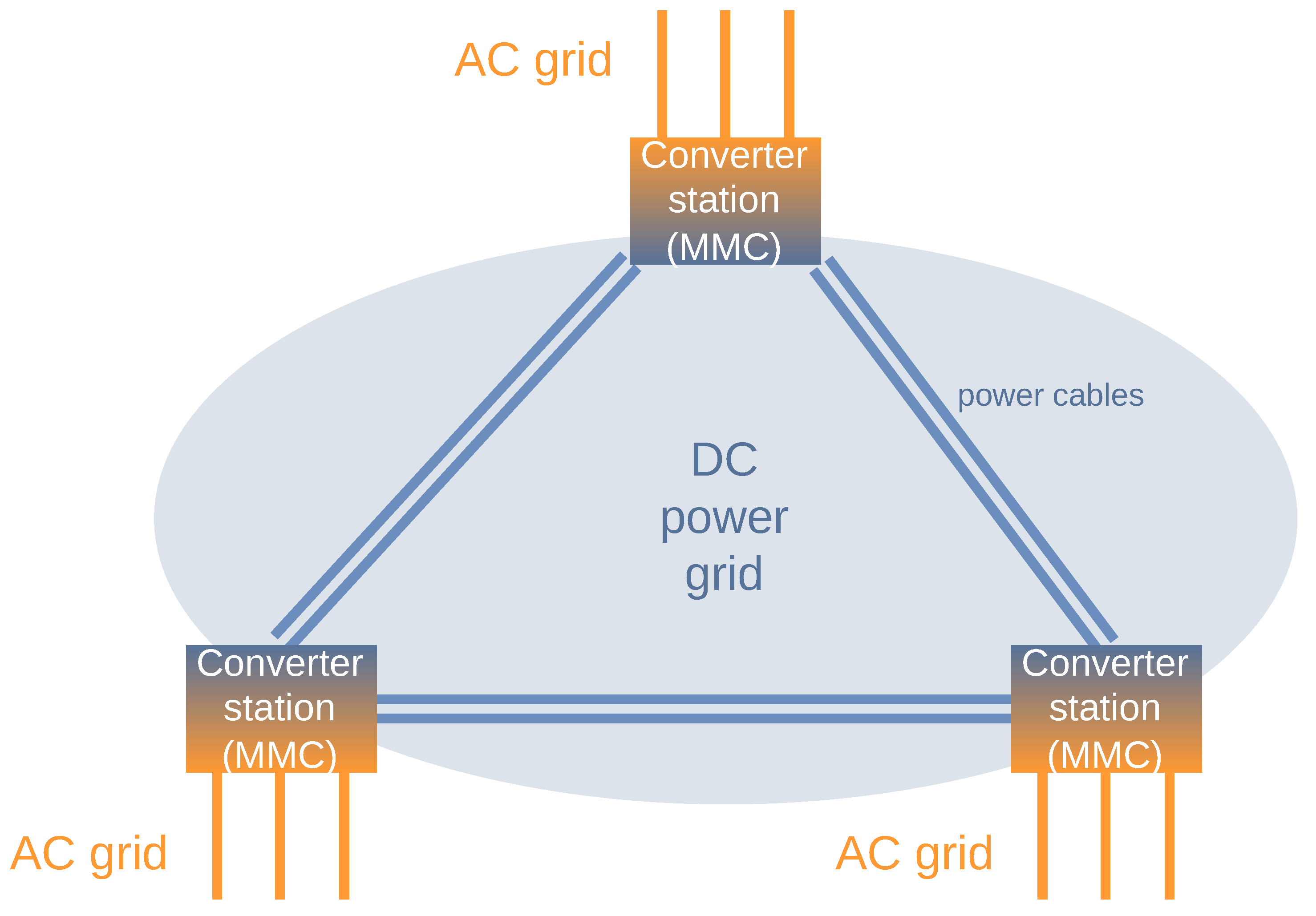
The basic MVDC grid scenario is shown in Figure 1 based on the topology given in ref. [8]. As proposed by the authors, the MVDC grid is established by converter stations, the Modular Multilevel Converter (MMC). The MMCs establish control and protect the AC and DC grid, also in cases of unexpected fault conditions [10]. Figure 1 exemplarily shows three MMCs that are fully interconnected via DC power cables. However, other configurations with a different amount of MMCs or an altering power grid topology are possible. Each MMC is also connected to a conventional three-phase AC grid.
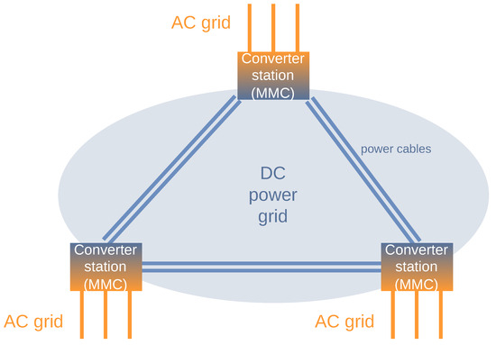
Figure 1.
Scenario: Medium voltage DC grids (based on the topology in [8]).
Each MMC in the MVDC grid is described by its own operating status. According to ref. [10] an MMC’s power system state, among other values, is described by
- the external DC voltages (negative and positive ),
- the external AC voltages (three phases , , ),
- six internal voltages (, , , , , ),
- six internal currents (, , , , , )
- and six internal corresponding energies (, , , , , ).
The internal structure of an MMC is not explicitly relevant for this scenario, but it dictates the described MMC’s state data, which is the basis for the state exchange message format proposed by this paper.
One of the most challenging aspects in MVDC grids is the handling of faults in the grid. Investigations with regards to handling pole-to-pole-(PTP) just as pole-to-ground-(PTG)-faults in MVDC grids have already been conducted in several previous works like refs. [11,12]. These kind of short circuits, regarding the circumstances of high power networks with up to 50 kV (cf. [13]), may lead to very huge failure currents which may harm the MMCs and other grid components.
As described in the previous section, the control and fault handling in MVDC grids relies on stable and secure communication. Referring to fundamental security goals, confidentiality, integrity, and availability according to NIST FIPS 200 [14]—and in particular availability and integrity—are protection-worthy for the MVDC grid operation. Harming integrity by forged or corrupt exchanged state data (e.g., by message tampering, traffic replay or environmental influences) leads to inaccurate control actions of the converter stations with potential harm due to limited error handling capabilities. Attacks that affect the network’s availability like jamming or transmission infrastructures damages (links or networking components) lead to grid interruption and consequently power outages.
2.2. System Requirements
A suitable communication system for MVDC grids must fulfill several requirements in order to be considerable for state exchange of MMCs. For the sake of clarity, we group the requirements according to two different aspects, (1) performance and applicability aspects as well as (2) security aspects. Requirements of the former group must be fulfilled in order to provide an effective operation of the system. Requirements of the latter group must be fulfilled by a communication system in order to provide a reliable and secure operation. An overview is shown in Table 1.

Table 1.
Overview of requirements.
2.2.1. Performance and Applicability Requirements
Considering the scenario described above, we can derive a small set of crucial yet nontrivially satisfiable performance and applicability requirements. The most restrictive requirement of an appropriate state exchange approach is its need for ultra-low latency (ULL) and high transmission rate (HTR) of states. The state of one MMC must be communicated to another MMC with the least possible delay as indicated by previous works. Especially in the case of a fault, MMCs must be informed immediately in order to compensate very high currents and avoid component damage. That also motives the next requirement for prioritizing the latest state of an MMC (LSP). MMCs must always know the most accurate state of each other MMC in the grid. Blind spots in the timeline of an MMC’s state, on the other hand, are tolerable if the time gaps are small enough. We furthermore believe that suitable communication technology should be based on general purpose hardware and concepts (GP) in favor of supporting plain setups and avoid hurdles like expensive highly specific networking components and reliance on manufacturers. Another very important requirement is the ability for continuous operation (CO). Power grid components like MMCs will be online for years and so must be the state exchange system. An outage of the communication system for short time periods leads to an unsafe operation of the MMCs and eventually to an inoperability of the MVDC grid and its power supply for consumers. The CO requirement motivates two consequent requirements: the state exchange system must avoid complexity but rather strive for simplicity (SIM) and maintainability (MA) in favor of error tolerance. In terms of applicability, an important requirement is that the system does not limit the topological extensibility (TE) of the MVDC grid. Power grids grow with their supplied area like villages or cities. An MVDC grows by adding more MMCs into it and interconnect them with the existing MMCs. The state exchange network should be able to grow with the power grid and allow the inclusion of further MMCs into it. The TE requirement is not rated with the highest priority because it does not affect the effectiveness of the state exchange but rather affects the applicability in practice.
2.2.2. Security Requirements
The overall objective of a state exchange system must be continuous operation (CO) of the MVDC, which has been introduced in the previous section. Security requirements can be directly derived from this performance requirement. The permanent availability (AVA) of the state exchange is the immediate consequence and is in network architectures usually resolved via redundant hardware and software components. Another very important requirement is the integrity (INT) of the transmitted exchanged data. If an MMC receives state data that differs from real data of other MMCs – either manipulated by an attacker or by natural interferences – it adapts its own state accordingly. This may lead to damage in the power grid components. Protection against replay attacks (RP) is a subrequirement to INT with the same possible effects. Another related requirement is to provide the authenticity of the data (AUT). An MMC must be able to check, whether a received state originates from a trusted source or is brought into the system from an untrustworthy source like an attacker. The ability of the state exchange to provide confidential communication (CON) does not directly affect its continuous operation. However, malicious interception and comprehension of network traffic and MMC state information may be one step stone in the manipulation of MMCs and is consequently considered with a high priority.
3. Existing Approaches
This section gives an overview of existing research for communication systems in particular for MVDC grids and its control strategies (cf. Section 1).
3.1. MVDC and Smart Grids Communication
Some previous works [15,16] address the use of communication networks for MVDC grids for error handling. A centralized fault handling approach is presented in refs. [17,18]. The approaches do not specify the communication system itself in detail. An approach using Ethernet communication has been proposed in ref. [19]; the authors did not evaluate communication delays but assumed 100 μs based on estimations from [20]. Security measures are missing. In [21], the authors proposes an event-based communication system based on IEC 61850 and IEC 60870-5-104 with an assumed exchange delay of 250 μs based on the physical signal propagation delay and processing delay estimations. The approach, however, lacks an evaluation and affirmation of the assumed delays. Furthermore no network security measures are considered, which induce additional processing delay. In ref. [22] also a fault protection scheme for MVDC grids based on the rate of change in current and voltage (sampled each 200 μs) is proposed. The approach uses a communication channel between protective relays based on a bus system without transport security mechanisms.
The exchange of state information is also a crucial element in Smart Grids, rendering efficient communication networks an important element in the concept [23]. In ref. [24] a deterministic networking approach based on a hybridly used wired Time Triggered Ethernet (TTE) and a wireless 5G network is proposed for ultra-low-latency communication. Although wireless solutions are way more suitable in terms of maintainability and topological extensibility, they can be jammed easily, rendering them unusable for reliable state exchange in MVDC grids. Other approaches using 5G or wireless communication technologies (cf. [25]) are similarly inadequate. In ref. [26], the authors describe a secure communication architecture based on UPnP, HTTP and elliptic curve cryptography. With minimum latencies of 60 ms, the approach cannot be considered ultra-low-latency capable.
3.2. Real-Time and Deterministic Communication Systems
Fieldbus systems do usually have similar properties and requirements. Some commonly used systems encompass for instance the Process Field Network (Profinet) [27] or the Ethernet for Control Automation Technology (EtherCAT) [28]. They are usually work with a centralized clock and support synchronized and non-synchronized traffic. Profinet and EtherCAT base upon Ethernet but require specialized components and can then achieve latencies to a low three digit microseconds scale. They however come with certain usage restrictions, for instance for EtherCAT where most nodes cannot send on messages on their own but append their payload to a frame. Fieldbus systems are usually not secured in terms of confidentiality and authentication. Buses and Layer-2 Systems like EtherCAT or Ethernet Time Sensitive Networking (TSN) show further restrictions, as they cannot serve bigger networks, usually require cumbersome time synchronization and a dictated master–slave architecture.
4. A Protocol for Ultra-Low-Latency Secure State Exchange
Our protocol for ultra-low-latency secure state exchange (PULLSE) is designed for use cases in which groups of homogeneous components exist and any component (e.g., MMCs) needs to know the state of any other component in the same group. For a group of N components, a component consequently knows its own state and receives the state of N-1 other components over the network. PULLSE is capable of routing across different networks and not limited to the MVDC grid scenario. The following sections describe the mode of operation, a packet header with an exemplary extension of the packet header for the MVDC use case and communication security measures. Finally, we discuss suitable topologies for the MVDC grid use case.
4.1. Basic Communication Concept
Considering the LSP requirement from Section 2.2.1, we designed PULLSE as a connection-less protocol. Typical features of a connection-oriented protocols (as for instance TCP) like packet receipt confirmations, packet ordering and flow control induce non-beneficial overhead. Also resending lost packages is not reasonable, since they already describe an outdated state the moment the original packet has been transmitted.
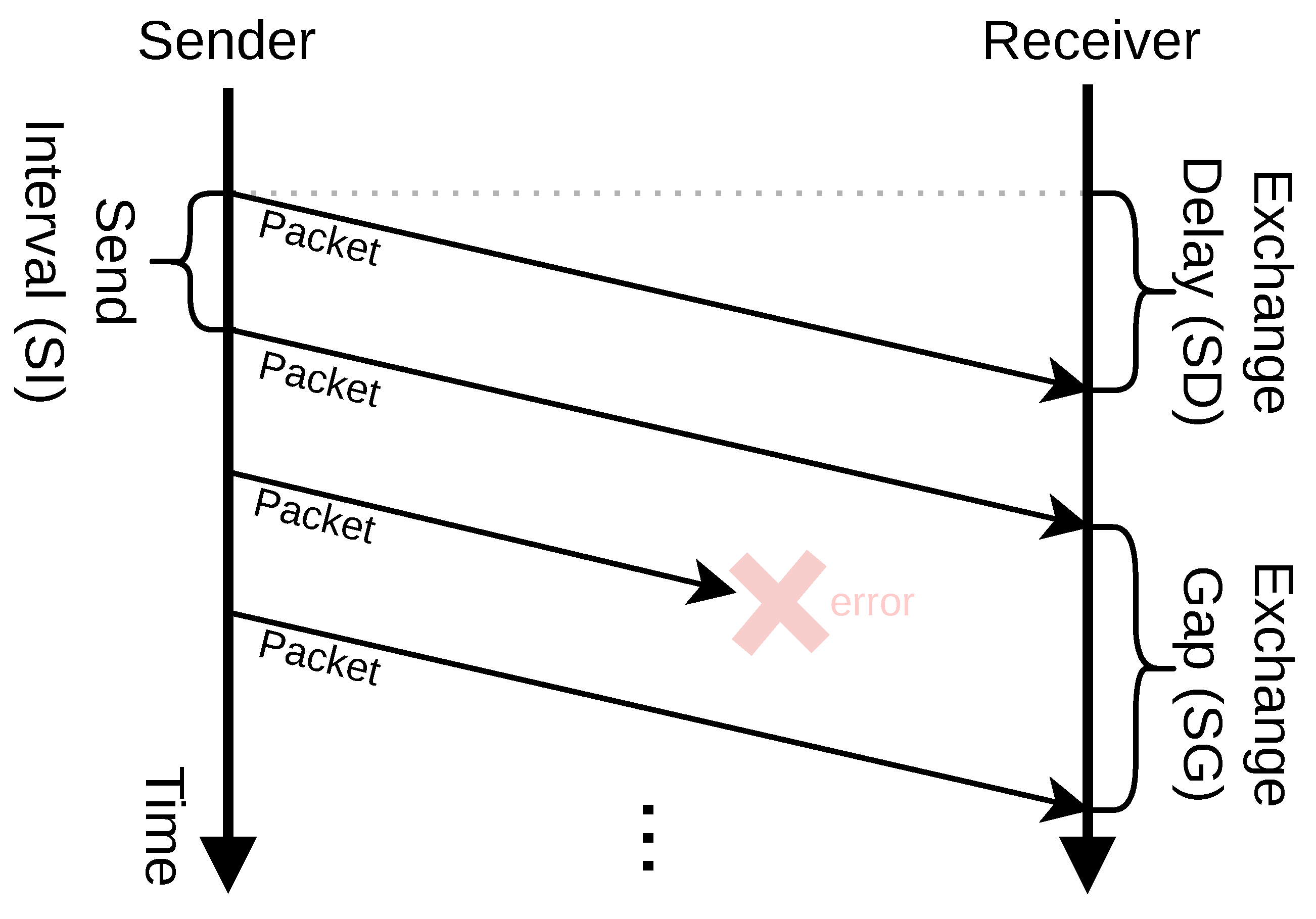
PULLSE consequently provides a stream of transmitted packets as shown in Figure 2. In this context, we define three essential factors for the state exchange and our protocol that are also shown in the figure:
- 1.
- Send Interval (SI): The interval a sender initiates the transmission of an exchanged packet.
- 2.
- Exchange Delay (ED): The time a packet takes from transmission start at the sender to its receipt at the receiver.
- 3.
- Exchange Gap (EG): The period between two consecutive packets a receiver got from the same sender. For instance, as shown in Figure 2, if one packet transfer fails, it is not considered in the specific EG value.
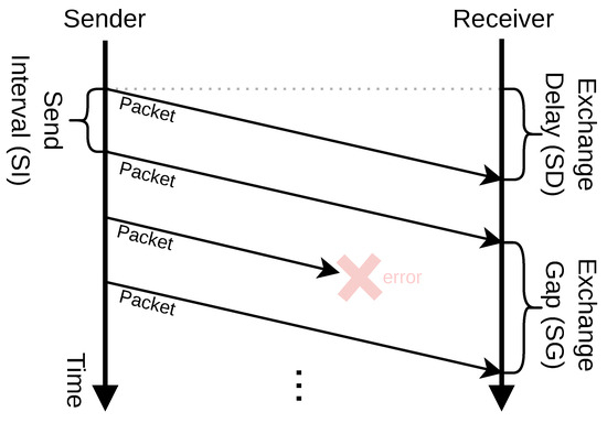
Figure 2.
PULLSE communication pattern and factors of effectiveness. The arrows indicate packet transfers, the dashed line indicates the same point in time at both sides.
Figure 2.
PULLSE communication pattern and factors of effectiveness. The arrows indicate packet transfers, the dashed line indicates the same point in time at both sides.
In PULLSE, the SI is the only adaptable factor at each sender. The ED and EG on the other hand, describe factors of quality of the communication system for a specific use case and both should be as low as possible. The ED indicates the freshness of the received packet, whereas the EG is an indicator for the freshness of the last known state of the specific sender.
Different use cases have different requirements in terms of acceptable maximum values for the ED and EG. The acceptable maximum ED in the MVDC grid use case depends on the grids dimensions and is expected to increase in a linear manner with the distance two MMCs have to each other, due to the lag of the spreading current in power faults. The EG on the other hand indicates the effectiveness of the communication and increases with an higher transmission error rates. The best possible value for the sync gap is the send interval, i.e., . The PULLSE approach consequently tolerates erroneous packet transmissions as long as the resulting EG still satisfies the use case’s needs.
4.2. Description of Packets
A packet needs to describe (a) meta-data for communication handling, (b) security-related meta-data and (c) the actual data as payload. We designed PULLSE to be usable for different use cases by allowing an extensible approach for the data. A PULLSE packet is consequently segmented into two parts:
- The PULLSE Basic Packet Format (PBPF) containing fixed information about communication- and security-related meta-data,
- and PULLSE Extended Packet Data (PEPD) that can be adapted to the specific use case PULLSE is used in.
The following Section describes the PBPF. Section 4.2.2 specifies a PEPD packet format for the MVDC grid use case and particularly the state exchange of MMC converters. Other PEPD formats may for instance be designed for other industrial use cases.
4.2.1. PULLSE Basic Packet Format (PBPF)
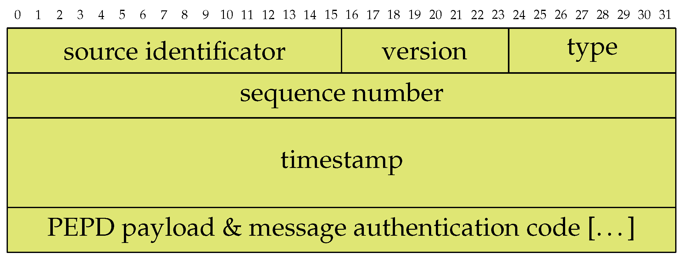
The PBPF is shown in Figure 3 as a protocol specification. The size of the fields correspond to the length and height of the cells in bits. Since PULLSE is designed for synchronizing a closed group of components, the communication data does solely require a source identifier field. Any other component in the same group is a destination by implication. Each packet furthermore contains a packet version field which allows the definition of different versions of one packet accordingly. The type field describes the content of the PEPD payload and message authentication code (MAC) fields. According to a given type identifier, the sender builds the message and protects it with a given MAC. The packet-wise sequence numbers are used to prevent replay attacks and to identify already known exchange packets. The timestamp is described as a 64-bit-value and is consequently capable of providig very high time resolution depending on the use case. For instance, it would provide microseconds accuracy without overflowing in over 580 thousand years.
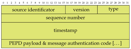
Figure 3.
Field alignment of the PULLSE Basic Packet Format (green fields are encrypted and integrity protected). The numbers on the figure’s top indicate bit lengths with each row consisting of 32 bits of data.
The last field of the PBPF is a generic placeholder for PEPD formats and a use case specific suitable MAC. The next section introduces an PEPD format that is suitable for the state exchange of MMCs in an MVDC grid.
4.2.2. PULLSE Extended Packet Data (PEPD) for MMCs
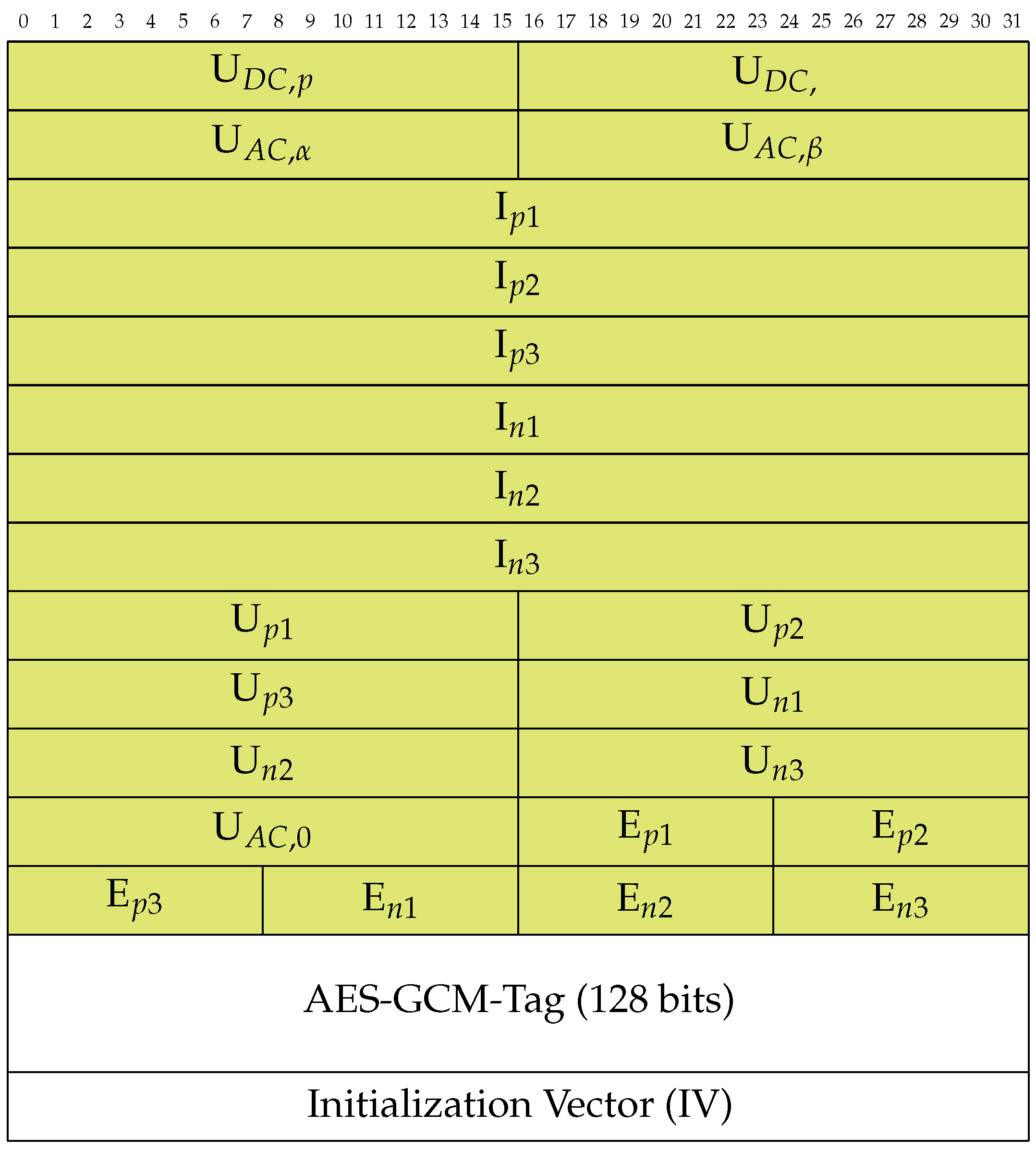
The state of an MMC in MVDC grids is primarily described in the scenario in Section 2.1. This results in the transmitted content described in Figure 4. For the MMC state exchange use case we additionally propose using AES-GCM. A corresponding authentication tag is added to the packet data. We describe the crypto design in detail in the next section. The protocol packet format also carries an unencrypted initialization vector (IV) in each message which serves as additional input for encryption and authentication. The IV must consequently be used to encrypt and decrypt the message.
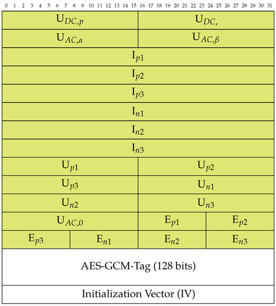
Figure 4.
PEPD format for the state exchange of MMCs in an MVDC grid (green fields are encrypted and integrity protected). The names of the variables correspond to the names in Section 2.1. The numbers on the figure’s top indicate bit lengths with each row consisting of 32 bits of data.
The fields’ lengths are chosen in a way that the overall packet does not contain dispensable information or precision since packet size may influence their processing time. We transmit currents (, around 1 kA) in high precision with four pre-decimals and two decimals with 32-bit fields. We describe the voltages (around 20,000 V) in a minor precision without decimals in 16-bit fields. The energies are represented in mega watts (MW) with a usual value of 20 MW.
4.3. Encryption and Authenticity
In order to meet the ULL and HTR requirements, the crypto system must cause as little delay as possible. Due to this criterion, asymmetric crypto systems disqualify themselves being too expensive. The crypto system must also be considered computationally secure and not exhibit flaws. As the encryption can be adapted to the specific scenario, PULLSE is used for, the following concept must be regarded in the context of the MMC state exchange. Due to these boundary conditions, we chose the Advanced Encryption Standard (AES) as a potentially suitable encryption system for ultra-low latency. As extensively shown in ref. [29], AES’ throughput may not be the most proficient (e.g., it is around ten times worse than for PRINCE in a hardware and four times slower than for SPECK in a software implementation); however, AES is still a fast algorithm and has several practical advantages:
- It is extensively tested and serves well for present protocols like WPA3 (for Wireless LAN) or TLS 1.3 (e.g., for online banking).
- Currently available COTS CPUs usually support hardware acceleration for AES.
- In some operation modes like EAX and GCM, AES supports authenticated encryption.
We exploit the latter advantage for ensuring integrity and authenticity of exchanged data in our concept, as we describe in the following section. We use AES with a key size of 128 bits, since it shows a performance advantage of 40% compared to a key size of 256 bits according to [30]. The use of 256 bits keys could be reasonable to examine in the era of quantum computers, but is not part of this paper.
In order to ensure the integrity and authenticity of state data, a combined approach is preferred in order to minimize processing overhead and delay. In our approach, we rely on the authenticated encryption capabilities of AES-128-GCM. We can then unite encryption, integrity and authenticity protection in only one algorithm that has hardware support on most COTS CPUs. Consequently an 128-bit AES-GCM authentication tag is generated for each message and appended to it (cf. Figure 4).
4.4. Key Management and Initialization Vectors
The communication key of the state exchange system must be renewed in a recurring manner due to two major reasons:
- 1.
- Minimization of the probability of key leakage to attackers based on intercepted packets.
- 2.
- Prevention of reuse of initialization vectors (IV).
The key renewal interval especially depends on the number of hosts in a state exchange group, which effectively divides up the IV space, as well as the update interval. For a 32-bit IV space (cf. Figure 4), update interval and the number of hosts N, the key renewal interval must be met in seconds in worst case, in order to prevent the reuse of IVs, is shown in Equation (1).
For instance, an MVDC grid with three converter stations and an update interval of 100 μs (0.0001 s) requires a key update cycle of or 39.7 h. The key renewal of the nodes must be done simultaneously in a matter of tens to few hundreds of microseconds. Otherwise, the EG may become too large resulting in the nodes having outdated state information. Several key management approaches already exist, for instance based on the Diffie-Hellman algorithm and Shamir’s secret sharing [31] or based on physically unclonable functions (PUFs) [32]. As we describe later in Section 7, we want to design the key exchange via a separate control channel as our future work. We want to avoid the temporal challenges of the key exchange here by installing a list of keys on each node, which are bound to certain ranges of the IV. Consequently, both the sender and all recipients always know which key to use for a certain packet by its IV. Since IVs are reused over time, already-used keys must be invalidated.
4.5. Network Topologies
Figure 5 shows two possible communication topologies (using Ethernet) for the state exchange system in the context of our MVDC grid scenario with three MMCs/nodes discussed in Section 2. We propose both, the star topology (cf. Figure 5a) and the directed ring topology (cf. Figure 5b) as being suitable as we expect both to offer a good trade-off between performance, maintainability and topological extensibility.

Figure 5.
Suitable communication topologies for MVDC grids.
The star topology is expected to yield most performance since any packet is sent to the central network switch, then duplicated and forwarded towards every other node. Given that the network switch offers sufficient capacities, every node should be synchronized in the same time period, depending on the communication wiring distances and forwarding delay of the centralized switch. The topological extensibility, however, may be limited, since every new node must be connected to the centralized switch, which is difficult in larger urban scenarios.
The directed ring topology, however, may perform worse with an increasing number of nodes. The maximum delay for the ring in seconds for is expected to be as shown in Equation (2).
N is the number of nodes, the average distance between two nodes, the propagation delay in the communication medium and F the packet forwarding delay per node. F as a forwarding delay can be seen as a composite value uniting several factors of delay at each node, for instance for data processing and data queuing. However, we expect a ring topology to show advantages over the star topology in terms of extensibility, since further nodes can be easily connected to the ring along each communication link. The maximum geographical size of the network must be planned ab initio.
4.6. Availability
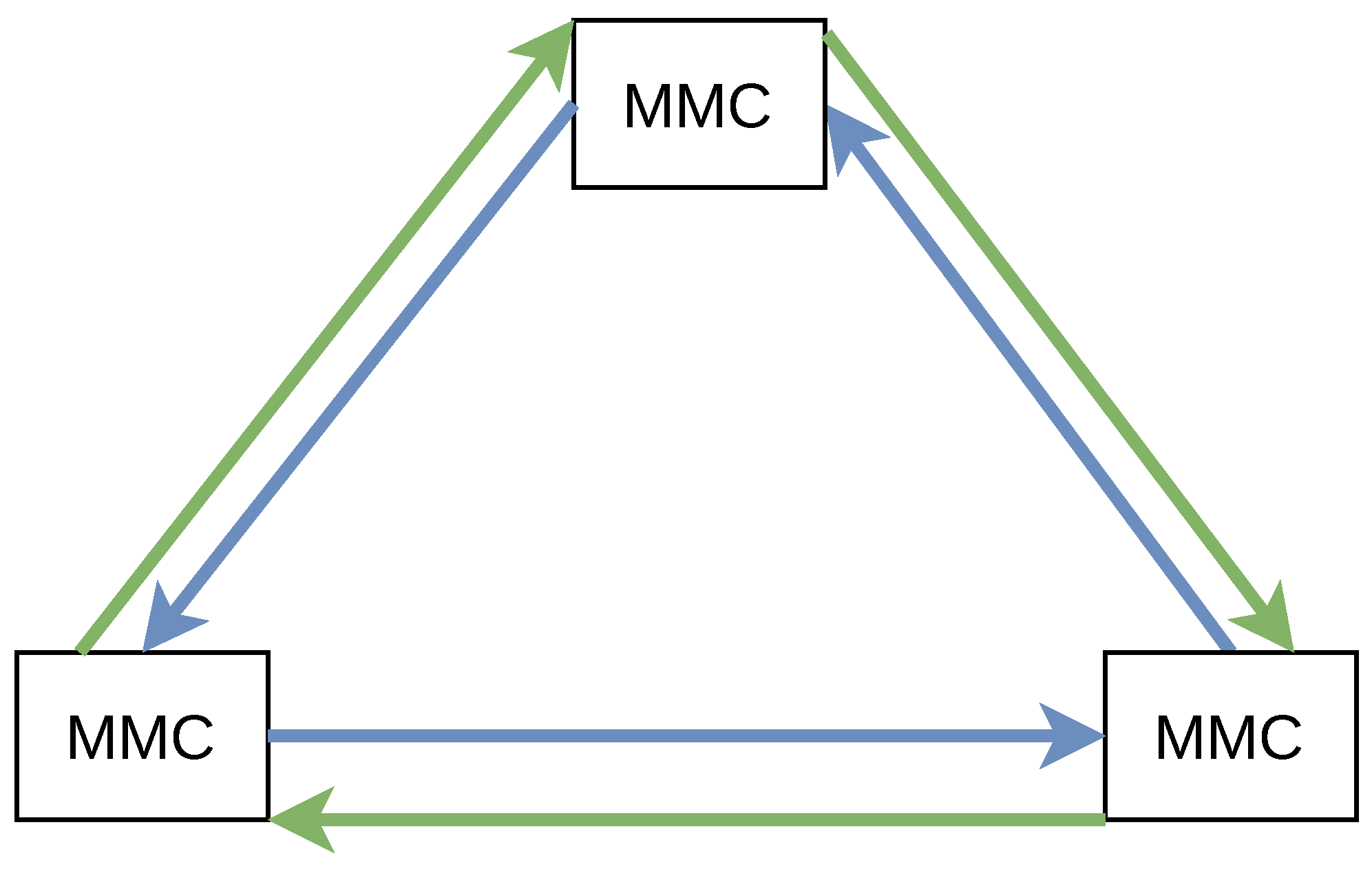
The availability of the communication system being the most important requirement can only be achieved via redundancy of the networking and wiring components. For the star topology (cf. last section), the centralized networking switch, the communication cables as well as the networking components for each node must be set up in a redundant manner. For the directed ring topology, we suggest to set up an additional ring working in the opposite direction, as it is illustrated in Figure 6. Nonetheless, networking components (e.g., network switches) on each node must be also set up in a redundant manner.
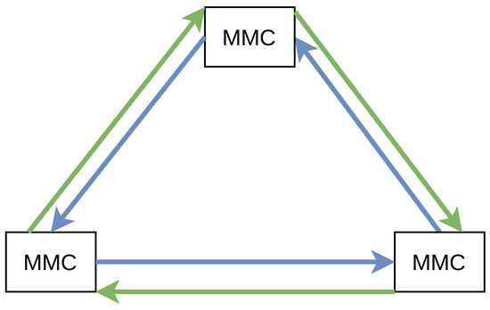
Figure 6.
Improved ring topology. The arrows show the communication direction of the two individual channels.
It is important to note, that both rings are used simultaneously. That means that each node continuously sends its states in a redundant manner via both directed ways. As the receipt of packet duplicates is an expected normal behavior, each node must discard a duplicate on arrival. However, duplicate packets can contribute to error correction in that case. If a node detects a deficient network packet (via authentication tag check), a subsequently following duplicate network packet may be in its original condition and can replace it with minimal additional delay (as both packets’ transmission has been initiated simultaneously).
For a redundant star topology (e.g., multiple central network switching with multiple physical communication cables connecting each node) there are different types of approaches to address the availability demands. The first one is to use a primarily link to each node and having one or more additional links as failover nodes. This is the usual solution in networking as the network can reconfigure itself by means of approaches like the Spanning Tree Protocol (STP) or its improvements like the Rapid Spanning Tree Protocol (RSTP). A performance evaluation conducted in [33] however indicates, that RSTP performs in the order of tens of milliseconds, which is not fast enough for our use case and opens a gap for failures and component damage. The study also outlines that other factors like link-down detection contribute to the overall delay, rendering it even more unusable for our use case. Consequently, another theoretical solution would be also using all redundant communication lines simultaneously, offering similar advantages (error correction, no failover) like the counteractive dual-ring topology.
5. Results and Evaluation
We implemented the PULLSE system in C in order to avoid additional runtime overhead by background processes of higher languages like garbage collection procedures. For the encryption with AES-128-GCM, we used the mbedtls-library (https://github.com/Mbed-TLS/mbedtls (accessed on 2 August 2025)) due to its focus on resource efficiency.
We evaluated our solution on the one hand in a network simulation based on the ns-3 network simulator (https://www.nsnam.org) (see next section) and on the other hand in a laboratory environment with a two-node-setup (see Section 5.2).
5.1. Simulation
In the simulation, we evaluated PULLSE system for the MVDC grid scenario according to the following dimensions:
- Performance for ring or star topologies and number of nodes
- Scalability in terms of node distance and number of nodes
5.1.1. Setup Description
In the default setup, we consider an MVDC grid with three converter stations distributed in a circular arrangement in distances of 20 km. The send interval (SI) is 200 μs and the message error rate is 1%. Forwarding delay for the central network switch in the star topology and for each converter station in the ring topology is 20 μs. We use IP and UDP atop the Ethernet Frame to transport the PBPF and PEPD for MMCs format. The approach also supports routing and service multiplexing.
ns-3 provides simulations in a discrete and reproducible manner and independently from the hardware specifications of the evaluation system or other influences. Consequently there is no jitter in the results. We chose the width of the data points’ whiskers consequently to indicate the proportion of data points matching that time value.
5.1.2. Scalability Evaluation
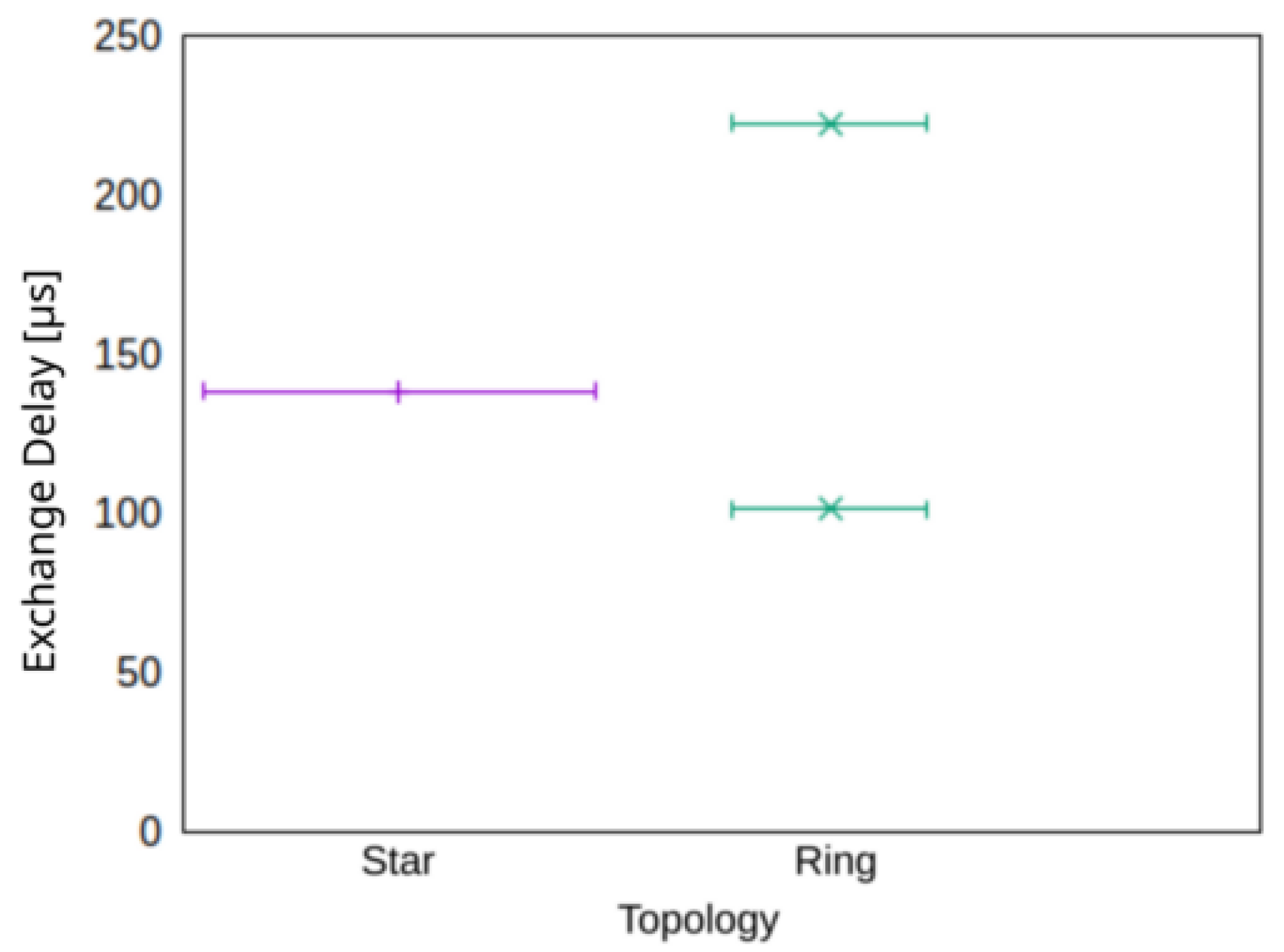
A direct comparison of a ring and a star topology in terms of exchange delay is shown in Figure 7 for three nodes. The evaluation shows that while the star topology can provide a homogeneous exchange delay for all nodes, the exchange delay in the ring topology differs according to the hop-distance from the sender and the individual receiver. The validity of Equation (2) is underpinned here.
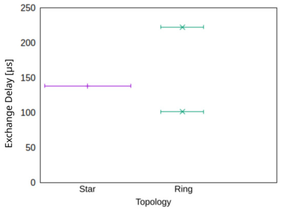
Figure 7.
Exchange delay for star and ring topologies. The width of the whiskers corresponds to the proportion of data points.
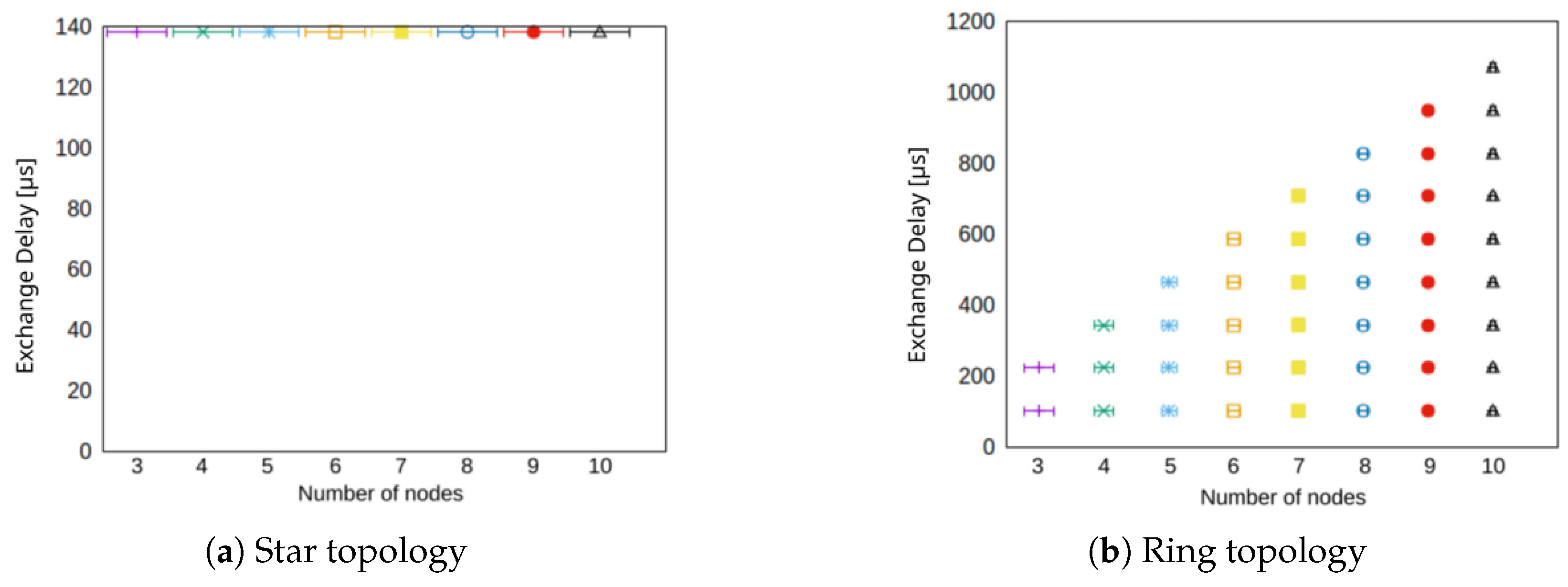
A comparison of the star and the ring topology in terms of network size in number of participating nodes is shown in Figure 8. For the star topology (cf. Figure 8a) the exchange delay is independent from the number of nodes. That is, presuming that the central network switch has sufficiently resources, because the communication from a source node to any destination node always takes two hops. The ring topology (cf. Figure 8a) on the other hand meets the expectations from the performance simulation. For each additional node in the network, the exchange delay increases by another hop’s delay.
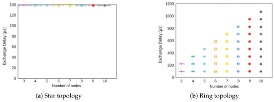
Figure 8.
Exchange delay for different number of nodes in the network for star and ring topology.
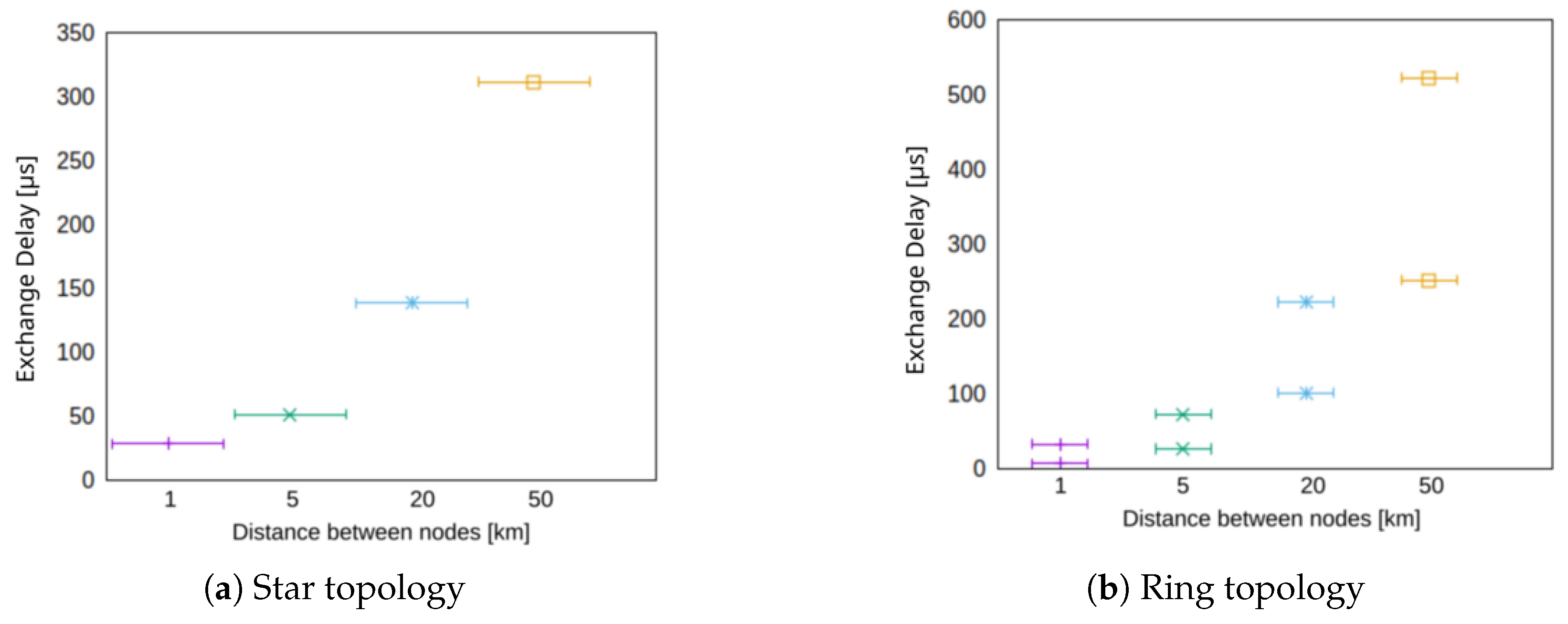
The scalability of our approach in terms of geographical distance between the nodes is investigated in Figure 9. The exchange delay for both, the star topology (cf. Figure 8a) just as the ring topology increase due to longer transmission delays. However, in the ring topology (cf. Figure 8b), the number of nodes is an additional factor that takes influence and the maximum exchange delay is as previously described in Equation (2).
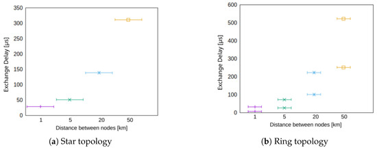
Figure 9.
Synchronization duration for different node distances for star and ring topology for three nodes.
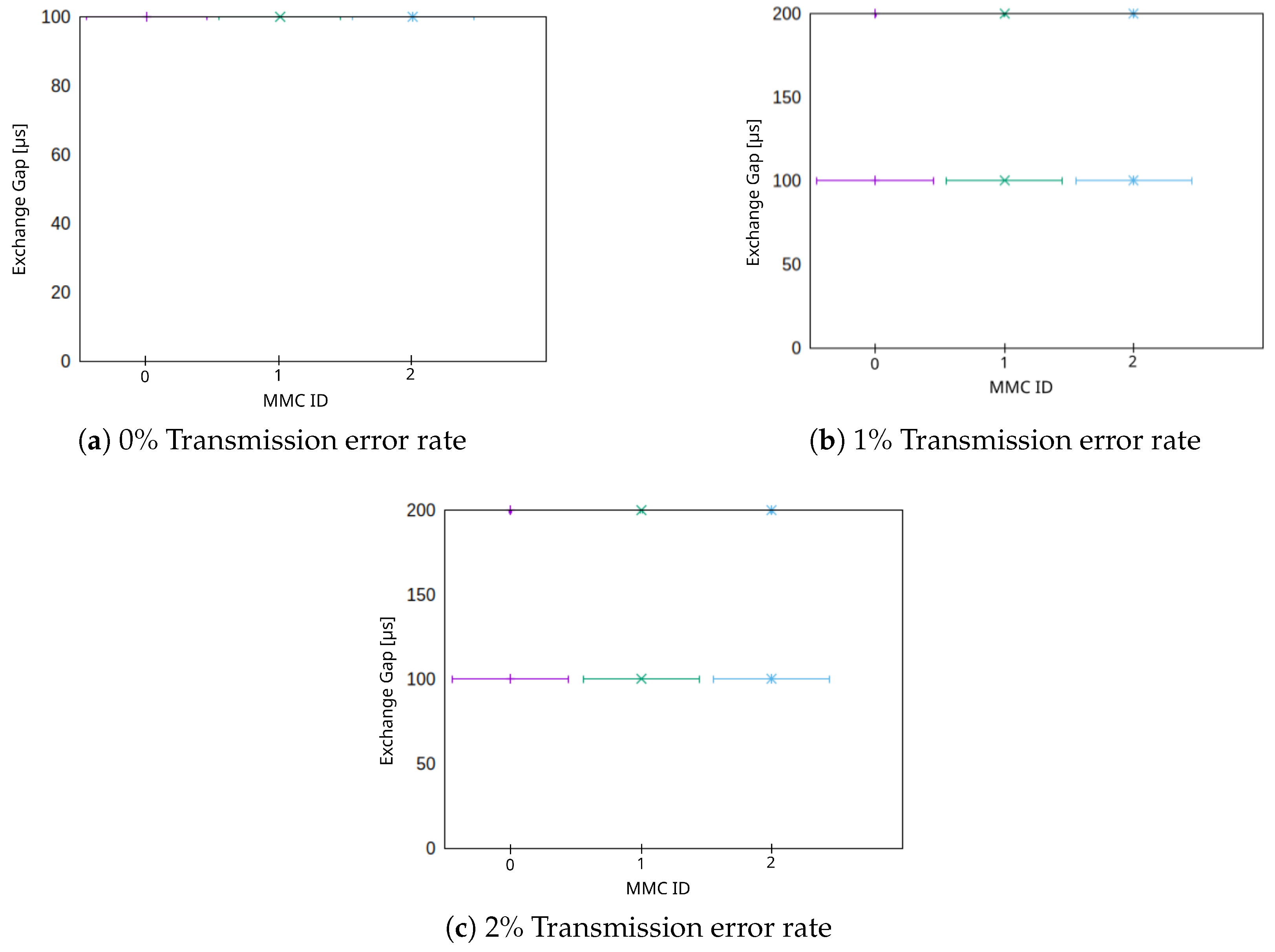
Another important factor which must be evaluated is the exchange gap (EG) (cf. Section 4.1). According to our simulations, the only real impact on the EG is obtained by two factors: The send interval (SI) and the error rate of the communication channel. The SI on the one hand determines the minimum EG which can be observed in the network. The error rate of the communication channel, on the other hand, influences—by rendering transmitted packets unreadable by the receiving nodes—the distribution of observed EGs. This observation is identical for the star or ring topology, as shown in Figure 10. We analyzed three different reasonable error rates of 0%, 1% and 2% packet loss. The minimal observed EG is the SI, which is 100 μs in this simulation. In Figure 10a, all nodes observe only these values (on the very top of the figure). For higher error rates of 1% (cf. Figure 10b) and 2% (cf. Figure 10c), we can also observe that some cases can be observed where the EG is 200 μs (again on the very top of the figures). The distribution of EGs is also directly determined by the error rate. Our simulations show, that for 1% error rate, 99% of observed EGs correspond with the SI (100 μs) and 1% correspond with μs. A similar distribution can be observed for 2% error rate with 2% observed EG of and 98% observed EG with the same value as the SI. EGs of 200 are expected results; as single messages are dropped due to transmission errors, the EG grows by another factor of the SI. Hence, depending on the transmission channel’s quality, we can expect with (without 0). The highest acceptable EG depends on the specific use case. Furthermore, for the MVDC grid use case, it depends on the grid control algorithm, whether gaps in which MMCs do not have fresh date can be compensated (e.g., by local measurements).
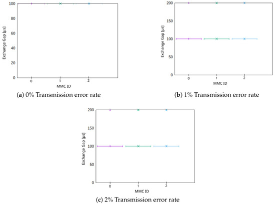
Figure 10.
Impact of packet error rate on the exchange gap (EG) for the star and ring topology for three nodes.
5.2. Laboratory Environment
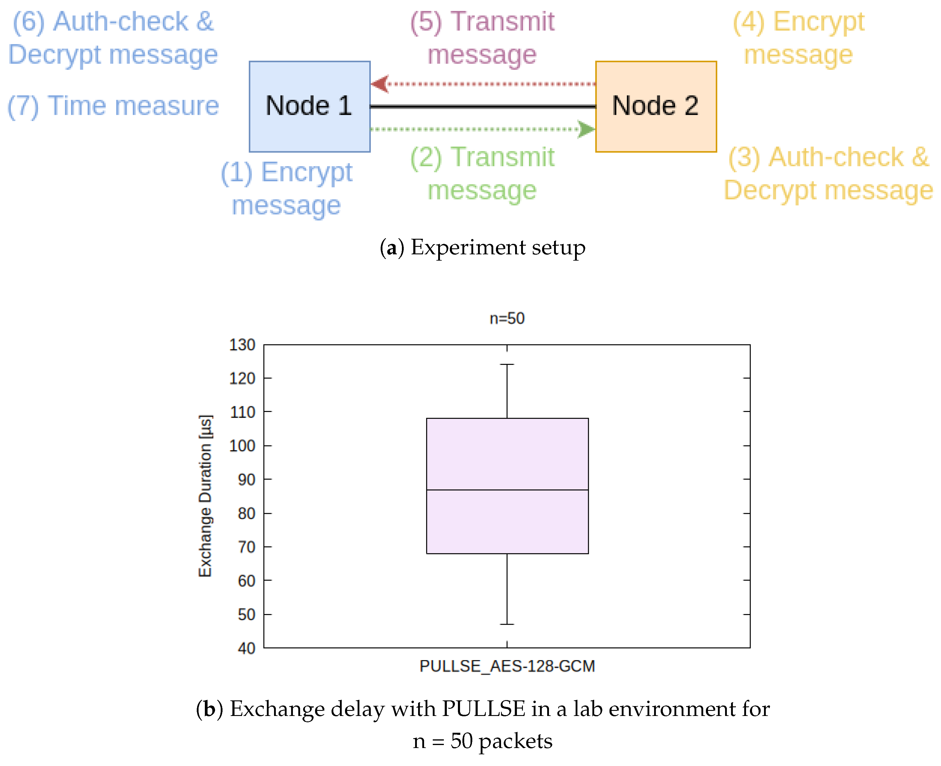
Due to the deterministic behavior of the simulations, they cannot indicate the suitablility of AES-128-GCM for encryption and authentication. For this purpose we augment the previously described simulations by a small but real in-lab test setup, which can show real processing and queuing times, which have been simulated before. In a laboratory setup with two nodes (shown in Figure 11a), we used a COTS-Notebook (Node 1) with a AMD Ryzen 7 PRO 4750U CPU and another node (Node 2) with a Intel i5 CPU, both using consumer network cards and running on Ubuntu Linux with dynamic preemption (PREEMPT_DYNAMIC). Both nodes are connected via a three meter long twisted pair cable. In order to emulate forwarding delays, we measure round-trip times from Node A to node B and back again to node A, including decryption and reencryption on node B. The course of the experiment is also shown in Figure 11a. Node 1 generates and encrypts a PULLSE message, as well as sends it towards Node 2. Node 2 checks the message for integrity and authenticity via the AES-GCM-Tag and decrypts it. Afterwards Node 2 takes the same message, which still includes the timestamp generated by Node 1, reencrypts and transmits it towards Node 1. Node 1 then conducts authenticity and integrity checks and message decryption. Afterwards it extracts the timestamp and compares it with the locally elapsed time. By not only forwarding a message, but also decrypt and reencrypt them at the second host, real processing and queuing times can be observed and evaluated. The measurements consequently also only rely on the clock of Node 1.
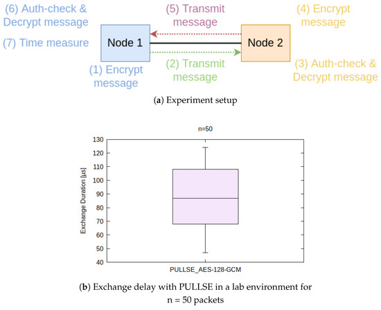
Figure 11.
Laboratory experiment with two nodes. Overview and results.
Figure 11b shows that in a laboratory environment, PULLSE allows exchange delays between 47 and 124 μs and a median of less than 90 μs with 50 samples. Assuming a propagation speed of almost 70% of light, the cable length has an effect of around 5 μs per kilometer. For 20 km cable length, the exchange delay would consequently be about 190 μs.
6. Discussion and Limitations
The simulations show that the star topology performs best for ultra-low-latency applications in PULLSE. The ring topology, however, is only suitable for networks with (a) few nodes, (b) a geographical limitation and using network components with a (c) low forwarding delay as all of these factors accumulate. Although the dual-ring topology described in Section 4.6 was not adressed in the simulations, we believe that it can improve the ring topology in terms of availability of the system and communication latency due to counteractive communication directions. In case of one ring’s operation being interrupted, the other ring can compensate the failure seamlessly. One effect is however, a higher latency for destination nodes that are further away from a source node (which is usually compensated by the antagonistic ring). Although the star topology is still expected to perform best in terms of latency-optimization, we believe that the dual-ring topology is cheaper to build. Especially expanding the MVDC grid with additional nodes is more economical if they can be placed along the already existing communication lines. Then, unlike for the star topology, no new communication lines must be placed underground or as overhead lines, but the existing cabling needs to be split for another node.
In practice, it is expectable that delays may be higher than in a simulation, for instance due to processing times that are not considered, jitter (disregarded here) or unpredictable events. In order to be able to estimate the practical feasibility of our approach, we tested the communication in a small two-node network in a lab environment. The results show that PULLSE is capable to exchange the state of nodes in geographical bigger networks in significantly less than 1 millisecond. All security requirements stated in Table 1 can be fulfilled, though AUT only partially, as explained in the next paragraph. Also, most performance and applicability requirements can be fulfilled. TE depends primarily on the network topology: we expect the ring topology—despite its performance limitations—to be easily extendable along existing wiring compared to the star topology.
The results however depend on network-topological constraints and performant networking switching. Additionally, PULLSE has only been evaluated in a dedicated network without other traffic due to the MVDC grid use case. In favor of being less vulnerable against faults and interferences, we recommend isolated networking infrastructure for critical power supply systems. Another limitation is the use of a unified group key for encryption and authentication as stated in Section 4.3. It allows assuring that a message originates from one source of trusted nodes in a network. Hence, a maliciously crafted state exchange packet from a compromised node with forged fields cannot be effectively prevented, but requires additional measures beyond this paper’s focus. We believe that also an individual key for each node to node channel cannot effectively mitigate negative impacts of a compromised node, since any node has to communicate with any other node. A compromised node might trick other nodes into diverging states (e.g., by telling any other node a different state about itself), also probably leading to failure and maybe damaging the power components. Hence, it is very important to protect and harden nodes and consequently mitigating the compromise of a node. Furthermore, a node-based IDS system can help detecting the deviation of transmitted states with the actual states of a node.
7. Conclusions and Future Work
In this paper, we presented a lightweight protocol for ultra-low latency and secure state exchange (PULLSE), along with an extendable protocol header format for different use cases and a specific manifestation of the protocol extensibility for the state exchange of MMCs in an MVDC grid. We could show that by adhering to certain prerequisites, as dedicated communication channels, topological conditions with duplex-channels and connection-less communication, commercial Ethernet can be used for real-time applications. We used AES-128-GCM for encryption, message authentication and data integrity checking. In simulations and a laboratory setup, we could show that PULLSE allows a state exchange of nodes in a dedicated network within less than 200 μs on consumer hardware. The core of PULLSE is intentionally designed in a minimal method in order to meet (a) demands for real-time latency and (b) fault resistance. The management of PULLSE, however, requires additional functionality like cipher selection (i.e., alternatives to AES) and initialization, cipher key management and performance management. As future works, we plan to design an additional control channel to a centralized controller for suchlike management functions. This channel is supposed to be realizable over a public network infrastructure such as the Internet.
Author Contributions
Conceptualization, M.S. and W.H.; methodology, M.S. and W.H.; software, M.S.; validation, M.S.; requirements analysis, M.S. and W.H.; investigation, M.S. and W.H.; data curation, M.S.; writing, M.S. and W.H.; visualization, M.S.; supervision, W.H.; project administration, M.S. and W.H.; funding acquisition, W.H. All authors have read and agreed to the published version of the manuscript.
Funding
This research work has been carried out within the project DEFINE and is funded by dtec.bw—Digitalization and Technology Research Center of the Bundeswehr, which we gratefully acknowledge. dtec.bw is funded by the European Union—NextGenerationEU.
Institutional Review Board Statement
Not applicable.
Informed Consent Statement
Not applicable.
Data Availability Statement
The original contributions presented in this study are included in the article. Further inquiries can be directed to the corresponding author.
Conflicts of Interest
The authors declare no conflicts of interest.
Abbreviations
The following abbreviations are used in this manuscript:
| AC | Alternating current |
| AES | Advanced Encryption Standard |
| AUT | Authenticity |
| AVA | Availability |
| CO | Continuous operation |
| CON | Confidentiality |
| COTS | Commercial-off-the-shelf |
| CPU | Central Processing Unit |
| DC | Direct current |
| ED | Exchange delay |
| EG | Exchange gap |
| FIPS | Federal Information Processing Standards |
| GCM | Galois Counter Mode |
| GP | General purpose communication |
| HTR | High transmission rate |
| IEC | International Electrotechnical Commission |
| INT | Integrity |
| IV | Initialization vector |
| LSP | Latest state priority |
| MA | Maintainability |
| MAC | Message Authentication Code |
| MMC | Modular Multilevel Converter |
| MVDC | Medium voltage direct current |
| MW | Mega watt |
| NIST | National Institute of Standards and Technology |
| PBPF | PULLSE Basic Packet Format |
| PEPD | PULLSE Extended Packet Data |
| PULLSE | Protocol for Ultra-Low-Latency and Secure State Exchange |
| PTG | Pole-to-ground |
| PTP | Pole-to-pole |
| PUF | Physically unclonable functions |
| RP | Replay Protection |
| SI | Send interval |
| SIM | Simplicity |
| TCP | Transmission Control Protocol |
| TE | Topological extensibility |
| TSN | Time Sensitive Networking |
| ULL | Ultra-low latency |
References
- Roa, M.; Cantrell, W.; Cartes, D.; Nelson, M. Requirements for deterministic control systems. In Proceedings of the 2011 IEEE Electric Ship Technologies Symposium, Alexandria, VA, USA, 10–13 April 2011; pp. 439–445. [Google Scholar]
- Danielis, P.; Skodzik, J.; Altmann, V.; Schweissguth, E.B.; Golatowski, F.; Timmermann, D.; Schacht, J. Survey on real-time communication via ethernet in industrial automation environments. In Proceedings of the 2014 IEEE Emerging Technology and Factory Automation (ETFA), Barcelona, Spain, 16–19 September 2014; pp. 1–8. [Google Scholar]
- Jahromi, M.G.; Mirzaeva, G.; Mitchell, S.D.; Gay, D. Powering mobile mining machines: DC versus AC power. IEEE Ind. Appl. Mag. 2016, 22, 63–72. [Google Scholar] [CrossRef]
- Coffey, S.; Timmers, V.; Li, R.; Wu, G.; Egea-Àlvarez, A. Review of MVDC applications, technologies, and future prospects. Energies 2021, 14, 8294. [Google Scholar] [CrossRef]
- Korompili, A.; Sadu, A.; Ponci, F.; Monti, A. Flexible electric networks of the future: Project on control and automation in MVDC grids. In Proceedings of the International ETG Congress 2015; Die Energiewende-Blueprints for the New Energy Age, Bonn, Germany, 17–18 November 2015; VDE: Offenbach am Main, Germany, 2015; pp. 1–8. [Google Scholar]
- Cheng, Z.; Duan, J.; Chow, M.Y. To centralize or to distribute: That is the question: A comparison of advanced microgrid management systems. IEEE Ind. Electron. Mag. 2018, 12, 6–24. [Google Scholar] [CrossRef]
- Kaharević, A.; Ramos, J.C.; Jahn, I.; Ponci, F.; Monti, A. A review of HVDC and MVDC grid protection. In Proceedings of the 19th International Conference on AC and DC Power Transmission (ACDC 2023), Glasgow, UK, 1–3 March 2023; Volume 2023, pp. 271–280. [Google Scholar]
- Marquardt, S.; Dahmen, C.; Brueckner, T. Fault management in meshed MVDC grids enabling uninterrupted operation. In Proceedings of the PCIM Europe 2023; International Exhibition and Conference for Power Electronics, Intelligent Motion, Renewable Energy and Energy Management, Nuremberg, Germany, 9–11 May 2023; VDE: Offenbach am Main, Germany, 2023; pp. 1–10. [Google Scholar]
- Ji, Y.; Yuan, Z.; Zhao, J.; Lu, C.; Wang, Y.; Zhao, Y.; Li, Y.; Han, Y. Hierarchical control strategy for MVDC distribution network under large disturbance. Iet Gener. Transm. Distrib. 2018, 12, 2557–2565. [Google Scholar] [CrossRef]
- Dinkel, D.; Hillermeier, C.; Marquardt, R. Direct multivariable control for modular multilevel converters. IEEE Trans. Power Electron. 2022, 37, 7819–7833. [Google Scholar] [CrossRef]
- Zeng, Y.; Zou, G.; Wei, X.; Sun, C.; Jiang, L. A novel protection and location scheme for pole-to-pole fault in MMC-MVDC distribution grid. Energies 2018, 11, 2076. [Google Scholar] [CrossRef]
- Dai, Z.; Zhu, H.; Su, H.; Huang, M.; Ma, M. DC line protection for flexible MVDC distribution grid with renewable energy resources. In Proceedings of the 2018 IEEE Power & Energy Society General Meeting (PESGM), Portland, OR, USA, 5–10 August 2018; pp. 1–6. [Google Scholar]
- Fotopoulou, M.; Rakopoulos, D.; Trigkas, D.; Stergiopoulos, F.; Blanas, O.; Voutetakis, S. State of the art of low and medium voltage direct current (Dc) microgrids. Energies 2021, 14, 5595. [Google Scholar] [CrossRef]
- National Institute of Standards and Technology. Minimum Security Requirements for Federal Information and Information Systems; National Institute of Standards and Technology: Gaithersburg, MD, USA, 2006.
- Bryans, R.; Bebbington, M.; Yu, J.; Smith, K.; Knott, J.; Moon, A. Real time control of a distribution connected MVDC link (ANGLE-DC). In Proceedings of the 13th IET International Conference on AC and DC Power Transmission (ACDC 2017), Manchester, UK, 14–16 February 2017; pp. 1–6. [Google Scholar]
- Clerici, A.; Chiumeo, R.; Gandolfi, C. MVDC multi-terminal grids: A valid support for distribution grids improvement. In Proceedings of the 2020 AEIT International Annual Conference (AEIT), Catania, Italy, 23–25 September 2020; pp. 1–6. [Google Scholar]
- Nougain, V.; Mishra, S.; Pradhan, A.K. MVDC microgrid protection using a centralized communication with a localized backup scheme of adaptive parameters. IEEE Trans. Power Deliv. 2019, 34, 869–878. [Google Scholar] [CrossRef]
- Deng, Q.; Liu, X.; Soman, R.; Steurer, M.; Dougal, R.A. Primary and backup protection for fault current limited MVDC shipboard power systems. In Proceedings of the 2015 IEEE Electric Ship Technologies Symposium (ESTS), Old Town Alexandria, VA, USA, 21–24 June 2015; pp. 40–47. [Google Scholar]
- Monadi, M.; Gavriluta, C.; Candela, J.I.; Rodriguez, P. A communication-assisted protection for MVDC distribution systems with distributed generation. In Proceedings of the 2015 IEEE Power & Energy Society General Meeting, Denver, CO, USA, 26–30 July 2015; pp. 1–5. [Google Scholar]
- Sortomme, E.; Venkata, S.; Mitra, J. Microgrid protection using communication-assisted digital relays. IEEE Trans. Power Deliv. 2009, 25, 2789–2796. [Google Scholar] [CrossRef]
- Kassem, A.; Sabra, H.; Abdelaziz, A.Y.; Ali, A.; Abdel-Latif, K. Centralized event-based protection based on communication infrastructure of medium voltage direct current network. Ain Shams Eng. J. 2024, 15, 102731. [Google Scholar] [CrossRef]
- Park, N.G.; Lee, J.I.; Go, B.S.; Lee, S.J.; Kim, C.; Dinh, M.C. Design of Protection Strategy for MVDC Distribution Networks Considering Network Reconfiguration. Energies 2025, 18, 3292. [Google Scholar] [CrossRef]
- Matinkhah, S.M.; Shafik, W. Smart grid empowered by 5G technology. In Proceedings of the 2019 Smart Grid Conference (SGC), Tehran, Iran, 18–19 December 2019; pp. 1–6. [Google Scholar]
- Hu, B.; Gharavi, H. A hybrid wired/wireless deterministic network for smart grid. IEEE Wirel. Commun. 2021, 28, 138–143. [Google Scholar] [CrossRef] [PubMed]
- Fadel, E.; Gungor, V.C.; Nassef, L.; Akkari, N.; Malik, M.A.; Almasri, S.; Akyildiz, I.F. A survey on wireless sensor networks for smart grid. Comput. Commun. 2015, 71, 22–33. [Google Scholar] [CrossRef]
- Khan, S.; Khan, R.; Al-Bayatti, A.H. Secure communication architecture for dynamic energy management in smart grid. IEEE Power Energy Technol. Syst. J. 2019, 6, 47–58. [Google Scholar] [CrossRef]
- PROFIBUS Nutzerorganisation e.V. (PNO), PROFIBUS & PROFINET International (PI). PROFINET System Description. 2014. Available online: https://us.profinet.com/wp-content/uploads/2012/11/PROFINET_SystemDescription_ENG_2014_web.pdf (accessed on 2 August 2025).
- EtherCAT Technology Group. EtherCAT—The Ethernet Fieldbus. 2012. Available online: https://www.ethercat.org/pdf/english/ETG_Brochure_EN.pdf (accessed on 2 August 2025).
- Thakor, V.A.; Razzaque, M.A.; Khandaker, M.R. Lightweight cryptography algorithms for resource-constrained IoT devices: A review, comparison and research opportunities. IEEE Access 2021, 9, 28177–28193. [Google Scholar] [CrossRef]
- Schneier, B.; Whiting, D. A Performance Comparison of the Five AES Finalists. In Proceedings of the AES Candidate Conference, New York, NY, USA, 13–14 April 2000; pp. 123–135. [Google Scholar]
- Hanna, Y.; Cebe, M.; Mercan, S.; Akkaya, K. Efficient group-key management for low-bandwidth smart grid networks. In Proceedings of the 2021 IEEE International Conference on Communications, Control, and Computing Technologies for Smart Grids (SmartGridComm), Aachen, Germany, 25–28 October 2021; pp. 188–193. [Google Scholar]
- Gu, H.; Potkonjak, M. Efficient and secure group key management in IoT using multistage interconnected PUF. In Proceedings of the International Symposium on Low Power Electronics and Design, Bellevue, WA, USA, 23–25 July 2018; pp. 1–6. [Google Scholar]
- Pallos, R.; Farkas, J.; Moldovan, I.; Lukovszki, C. Performance of rapid spanning tree protocol in access and metro networks. In Proceedings of the 2007 Second International Conference on Access Networks & Workshops, Ottawa, ON, Canada, 22–24 August 2007; pp. 1–8. [Google Scholar] [CrossRef]
Disclaimer/Publisher’s Note: The statements, opinions and data contained in all publications are solely those of the individual author(s) and contributor(s) and not of MDPI and/or the editor(s). MDPI and/or the editor(s) disclaim responsibility for any injury to people or property resulting from any ideas, methods, instructions or products referred to in the content. |
© 2025 by the authors. Licensee MDPI, Basel, Switzerland. This article is an open access article distributed under the terms and conditions of the Creative Commons Attribution (CC BY) license (https://creativecommons.org/licenses/by/4.0/).

