Review

General Overview of Antennas for Unmanned Aerial Vehicles: A Review

1
Instituto de Telecomunicações, 3810-193 Aveiro, Portugal
2
Department of Electronics, Telecommunications and Informatics, University of Aveiro, 3810-193 Aveiro, Portugal
3
Agueda School of Technology and Management, University of Aveiro, 3750-127 Agueda, Portugal
*
Authors to whom correspondence should be addressed.
Electronics 2025, 14(16), 3205; https://doi.org/10.3390/electronics14163205
Submission received: 9 July 2025 / Revised: 5 August 2025 / Accepted: 9 August 2025 / Published: 12 August 2025
(This article belongs to the Section Microwave and Wireless Communications)

Abstract

Unmanned Aerial Vehicles (UAVs), commonly known as drones, are becoming increasingly important in multiple areas and various applications, including communication, detection, and monitoring. This review paper examines the development of antennas for UAVs, with a particular focus on miniaturization techniques, polarization strategies, and beamforming solutions. It explores both structural and material-based methods, such as meander lines, slots, high-dielectric substrates, and metasurfaces, which aim to make the antenna more compact without compromising performance. Different antenna types including dipole, monopole, horn, vivaldi, and microstrip patch are explored to identify solutions that meet performance standards while respecting UAV constraints. In terms of polarization strategies, these are often implemented in the feeding network to achieve linear or circular polarization, and beamforming techniques like beam-steering and beam-switching enhance communication efficiency by improving signal directionality. Future research should focus on more lightweight, structurally integrated, and reconfigurable apertures that push miniaturization through conformal substrates and programmable metasurfaces, extending efficient operation from 5/6 GHz into the sub-THz regime and supporting agile beamforming for dense UAV swarms.

1. Introduction

Unmanned Aerial Vehicles (UAVs), also known as drones, are vehicles that can operate either through remote control or by being programmed to fly autonomously, with their main advantage being the ability to fly without the need of an onboard pilot [1]. Two types of UAVs are shown in Figure 1, the fixed-wing drone in Figure 1a and the quadcopter in Figure 1b. They were originally developed for military tasks and, although they are still used in that field, they have found uses in other applications, such as search and rescue, surveillance, detection, monitoring, delivery services, and medical emergencies [2,3]. This increasing use of drones is mainly due to improvements in wireless communications, such as UAV-to-ground and UAV-to-UAV RF transmissions, satellite links, and 5G networks [1,4].
In these UAV communication systems, antennas are essential for maintaining a stable connection, allowing for real-time data transfer and efficient remote control. But, despite their importance, the integration of antennas into drones is constrained by various limitations, such as size, weight, and air resistance, which means that not all antennas can be mounted on or integrated into drones. Regarding their size, antennas must be compact enough to fit on the drone, which restricts possible frequency choices as higher frequencies yield smaller antennas, while lower frequencies result in larger ones. In terms of weight, an antenna needs to remain lightweight because if it is too heavy, it could prevent the drone from taking off or even flying, while also intensifying power consumption, reducing flight duration and battery efficiency [6,7]. Additionally, aerodynamic drag is a crucial factor when drones are flying because the antennas will create air resistance, which can affect the drone’s stability, control, and speed [8,9,10].
To overcome some of these challenges, miniaturization techniques are often applied. These methods are mostly used to reduce the antennas’ physical size using meander lines, fractal geometries, and slots or by employing material-based solutions like high-dielectric substrates and metamaterials, without sacrificing performance [11]. In addition to miniaturization, polarization and beamforming techniques also help optimize antennas’ performance in UAVs. Different polarization techniques can be used to achieve either linear or circular polarization, depending on the antennas’ design, by conducting modifications in the radiating element or by making adjustments in the feeding network, which can be achieved by the standard methods, using an inset feed or a coaxial cable, or by using couplers, switches, and phase shifters. Beamforming can be implemented through different methods, including beam-switching, beam-steering, beam-scanning, arrays, and multi-antennas, allowing better control of the radiation pattern and improving communication performance [12,13,14].
This paper presents a review of research from 2019 to 2024 on antennas for UAVs, which is organized in tables that include their main characteristics. This research was carried out using a Natural Language Processing (NLP)-based software to search and filter scientific articles in databases like IEEE Xplore, MDPI, Elsevier, and Springer. The main keywords for this research were antennas for drones, antenna miniaturization, and antenna systems for UAVs. These words were expanded using synonyms and related terms to improve the search coverage. A total of 538 articles were retrieved from the database. Out of these, 146 were read in detail and 50 were selected and cited in this paper due to their relevance to the topic under discussion. The articles that did not meet the main criteria—those published before 2019 or lacking a connection to the specific focus of this study, which is antennas for drones—were excluded. This review focuses on miniaturization methods, polarization strategies, and beamforming techniques to enhance UAV communication across various applications. It is divided into several sections: Section 2 reviews different types of single-element antennas commonly used in UAVs, including the dipole, monopole, horn, vivaldi, dielectric resonator (DR) antenna, and microstrip patch antennas. Section 3 presents a comparative analysis of the surveyed antennas, while Section 4 presents the miniaturization techniques, covering structural modifications and material-based approaches to reduce antenna size and improve the electromagnetic properties of the antenna. Section 5 discusses beamforming strategies, including beam-switching, beam-steering, beam-scanning, array-based approaches, and the use of multi-antennas. Section 6 provides a general discussion and, finally, Section 7 examines emerging trends and outlines future research directions. This is followed by the conclusions in Section 8.

2. Single-Element Antennas Used in UAVs

Choosing the right antenna depends on its intended use and application since each design offers different advantages in terms of gain, radiation pattern, polarization, and bandwidth. The most common antenna types used for UAV applications range from dipoles and monopoles to patches, vivaldis, DR, and horns, making the selection of the right antenna crucial.

2.1. Dipole

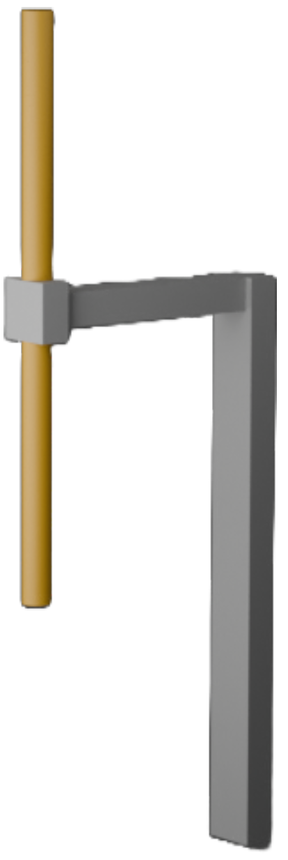
The dipole is one of the most basic antenna types. It consists of two conductive elements that radiate electromagnetic waves when an alternating current passes through them. The half-wavelength dipole ( λ /2) is the standard configuration for dipole antennas due to its combination of efficiency, simple design, and predictable radiation pattern [15]. This traditional antenna is illustrated in Figure 2. However, integrating these in drones is not always practical due to them being fragile (when exposed to vibrations and possible crashes) and because they are not easy to integrate into the drone structure. As such, other variations have been developed for UAV applications, each offering specific improvements over the conventional design.
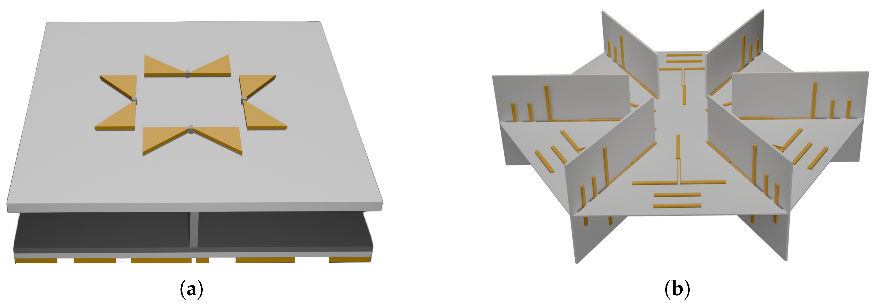
One variation of the dipole is the Cloverleaf Dipole, which achieves an omnidirectional radiation pattern and circular polarization through its design of four thin wires arranged in different angles. It is used in First-Person View (FPV), which is a system that provides immersive perspectives by transmitting live video from the operator’s viewpoint [16]. In drone applications, FPV transmits live video from the drone to the ground, allowing the operator to react quickly to the environment so that it can avoid accidents. For this reason, this type of system requires low latency, so it can balance image quality with responsiveness. In [10], because drones tend to move quickly and change direction often, for this application, circularly polarized antennas with omnidirectional radiation patterns were required to help maintain signal stability, regardless of the UAVs’ orientation and movement. Although none of the reviewed designs explicitly optimize for latency, the use of omnidirectional, circularly polarized antennas indirectly supports low-latency FPV video transmission by reducing signal loss due to orientation or multipath interference. It is worth mentioning that because the Cloverleaf is made of wires, it is just as fragile as other wire antennas. In addition to wire-based dipole designs, planar dipole antennas are also widely used in UAV applications due to their lightweight design and because they are easier to integrate into a drone’s structure. These types of antennas also improve bandwidth, directivity, and impedance matching, making them a practical choice for UAVs. There are different types of planar dipole antennas, each designed for a specific purpose. The Crossed Inverted-V Dipole is designed to enhance air-to-ground coverage and polarization diversity, facilitating stable UAV communication [17]. Some efforts have been made to turn the Cloverleaf Dipole into a planar configuration [18]. Although this design offers a near omnidirectional radiation pattern, without a reflector, and a directional pattern, with a reflector, the authors do not specify which type of polarization, which means that circular polarization is not confirmed. The Half Bow-Tie Dipole, shown in Figure 3a, improves bandwidth and impedance matching by adjusting its inclination angle, making it suitable for multi-band UAV communication systems [19]. The Planar Yagi-Uda Dipole achieves high gain and directivity to support UAV-to-UAV communication with full beam coverage [20], as shown in Figure 3b.
The Circular Folded Dipole achieves a compact design while improving impedance matching, which benefits applications in RFID devices, as well as sensor networks and wireless communication modules [21]. The Arrow-Shaped Dipole stands out by increasing directivity, which makes it suitable for UAV-borne radar applications [22], and the L-Shaped Dipole allows for beam-steering capabilities while being aerodynamic, thereby supporting high-performance UAV communication. It is used in military applications [23].
To highlight their key characteristics, the dipole antennas reviewed above are summarized in Table 1.
Most dipoles listed in Table 1 adopt a planar structure because planar antennas are easier to integrate into UAVs and are more robust compared to the conventional dipole. These antennas also help reduce aerodynamic drag [19] and are more compact [17,19,20,21,22,23]. Each individual dipole element has a directive radiation pattern, as seen in Table 1, and, when combined in an array, allows for a wide coverage, which is beneficial for communication systems [17,19,20,22]. When the dipole consists of wires, it maintains the omnidirectional pattern, as seen in [10], whereas in a planar form, it transitions to a directive radiation pattern, as observed in the radiation pattern column in Table 1. This is due to these antennas having a ground plane, which helps direct the radiation [17,19,20,21,22]. For example, the Cloverleaf antenna has a gain of 0 dBi, which corresponds to omnidirectional behavior [10], while the other dipoles listed in Table 1, except for [21], show higher gain values that are consistent with their directive patterns.
Regarding frequency, most dipole antennas operate at around 5 GHz, as seen in Table 1. In [19], the 5.03 GHz to 5.15 GHz band was used because it was officially allocated for UAV communications during the World Radiocommunication Conference (WRC) 2012. Meanwhile, ref. [21] used 915 MHz because it is part of the Industrial, Scientific, Medical (ISM) band (in the USA) and it is commonly used for RFID, LoRa, and other IoT applications. In this case, the antenna was not designed for UAV-to-ground communication but for detecting RF signals, and that is why it was designed to operate at a lower frequency. The others mentioned the operating frequency, but they did not explain why they chose it; this likely suggests that the designs followed the usual practices, so they did not give any technical reason. So, it is reasonable to consider that, for example, in [22], the use of the 10 GHz was because it belongs to the X band, which is frequently used in modern radar systems, aligning with the application the antenna was made for. Similarly, in [10], the antenna operated at 5.8 GHz, which is a frequency usually used for wireless communication applications.
Another aspect to consider is the bandwidth of the antenna; however, there is no universal definition to classify antennas as narrow bandwidth (NB), moderate bandwidth (MB), or wide bandwidth (WB). In other words, the numerical values for these categories are not defined. So, for the purpose of this review, the categories according to [24] were adopted. NB was less than 5% of the center frequency, MB was between 5% and 20%, and WB was greater than 20% of the center frequency [24].
In terms of bandwidth, the majority of these antennas do not have a wide band, which is a common characteristic of planar antennas. In [21], the antenna had a NB, while, in [10,17,22], the antennas had a MB; only in [19,20,23] did the antennas have a WB. So, in order to achieve a larger bandwidth, some design modifications had to be implemented. The majority of these articles [10,17,20,21,22,23] do not mention ways to improve the bandwidth, at least not directly. However, in [19], increasing the width of the bow-tie contributed directly to broadening the bandwidth.

2.2. Monopole

The monopole is an antenna variant of the dipole and consists of a single conductive element placed above a ground plane [25]. The quarter-wavelength monopole ( λ /4) represents the most popular configuration due to its simple structure and small dimensions, which results in a omnidirectional radiation pattern [26]. An example of a monopole antenna is illustrated in Figure 4.
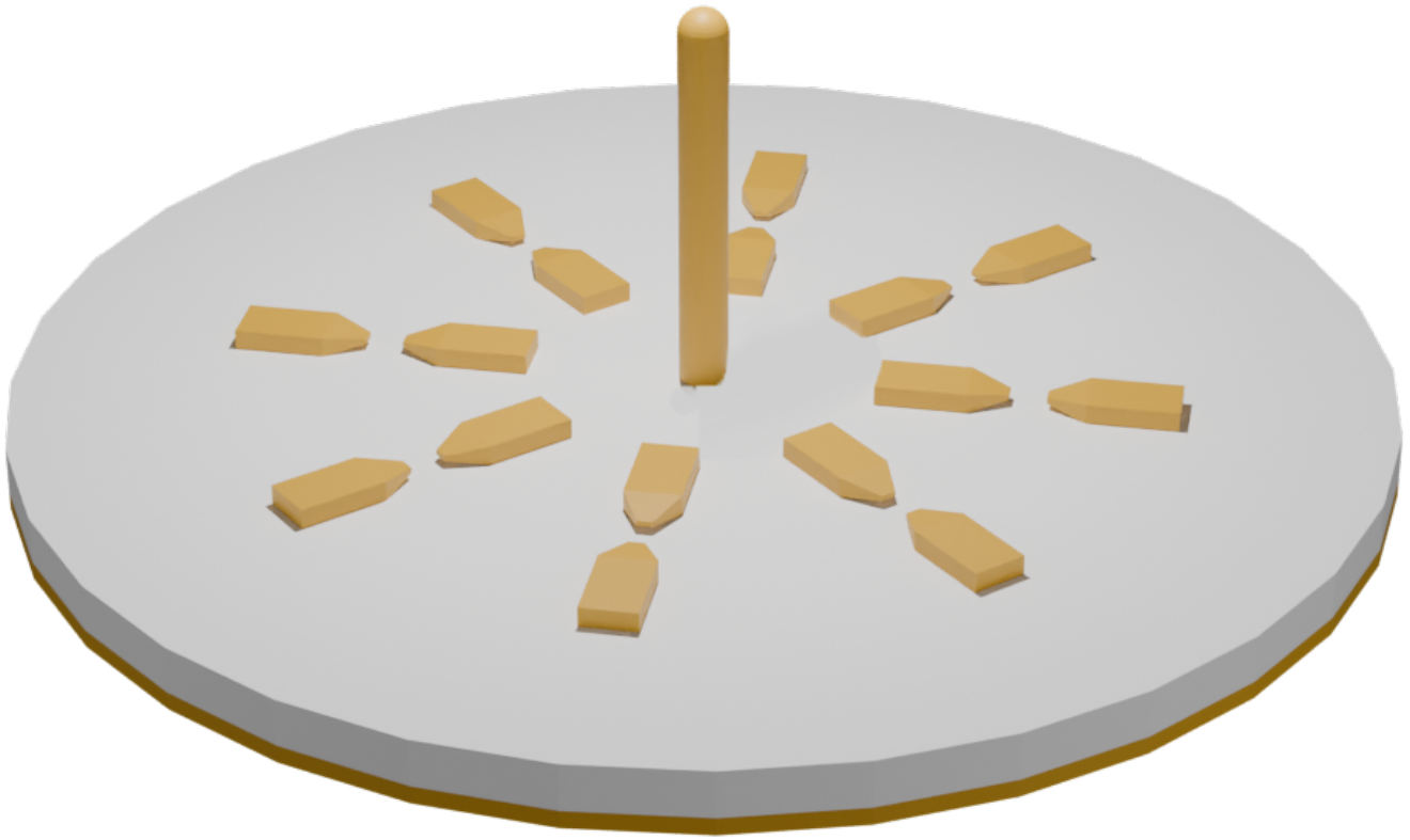
However, in UAV applications, additional design considerations are required to enhance antenna performance. These improvements are achieved by adding a substrate above the ground plane rather than the monopole itself, for example, in [27], Horizontal Parasitic Element Reflectors (HPERs) were added to the substrate, enhancing impedance matching and beam control, allowing the beam to be steered in eight directions using Positive-Intrinsic Negative (PIN) diodes, improving the directivity and gain. This antenna is illustrated in Figure 5.
In addition to wire-based monopoles, planar monopoles are also used in UAV applications, including the Meander Line antenna. This configuration is a common choice for UAVs because it achieves size reduction while keeping the operating frequency and the performance characteristics of the antenna [11]. The printed meandered monopole in [28] is designed to achieve a low height for UAV integration and, in [29], it was used to reduced the footprint for EMI sensing applications.
According to Table 2, meander lines are more used because, as already mentioned in Section 4.1, this design helps reduce the antenna’s size [28,29]. Regarding radiation pattern, monopoles typically exhibit an omnidirectional pattern, but, in [28,30], due to the combination of the radiating fields between the monopole and the patch and from the two coupled monopoles, respectively, with the feeding network adjusting the phase and power distribution, the radiation pattern became directive. There is also an antenna that achieves both omnidirectional and directive radiation patterns. In [27], a wire monopole was used, which naturally achieved the omnidirectional pattern. However, with the addition of a substrate with HPERs, the radiation behavior changed, making it more directional. In other words, when the HPERs are active, the radiation becomes directive; otherwise, the HPERs do not have any influence on the radiation pattern of the monopole, so the antenna keeps its usual omnidirectional pattern.
When it comes to frequency, the antennas in [27,28] operated at 5.09 GHz because this covers UAV ground control frequencies and UAV mission frequencies allocated at WRC under the International Telecommunication Union (ITU). In [29], the 100 MHz frequency was used because it belongs to the Very High Frequency (VHF) band, which is ideal for EMI sensing due to its longer range and lower noise levels. This frequency also complies with the CISPR 12 and CISPR 25 standards. Meanwhile, in [30], there was no justification for the use of 2 GHz, so it is reasonable to assume that this frequency was chosen because of its application, which involves Direction Finding (DF), which usually operates within certain bands that include this frequency [31].
In terms of bandwidth, refs. [27,29] had a NB, and, in [27], this happened because of the HPERS. The wire monopole itself had a bandwidth of 1400 MHz, but, due to the presence of the HPERs, the bandwidth turned out to be 120 MHz. So even though the HPERs enhanced directionality, they reduced the bandwidth. Both antennas from [28,30] had a MB. Overall, because these antennas are planar [27,28,29,30], they present smaller operating ranges.

2.3. Horn, Vivaldi, and DR

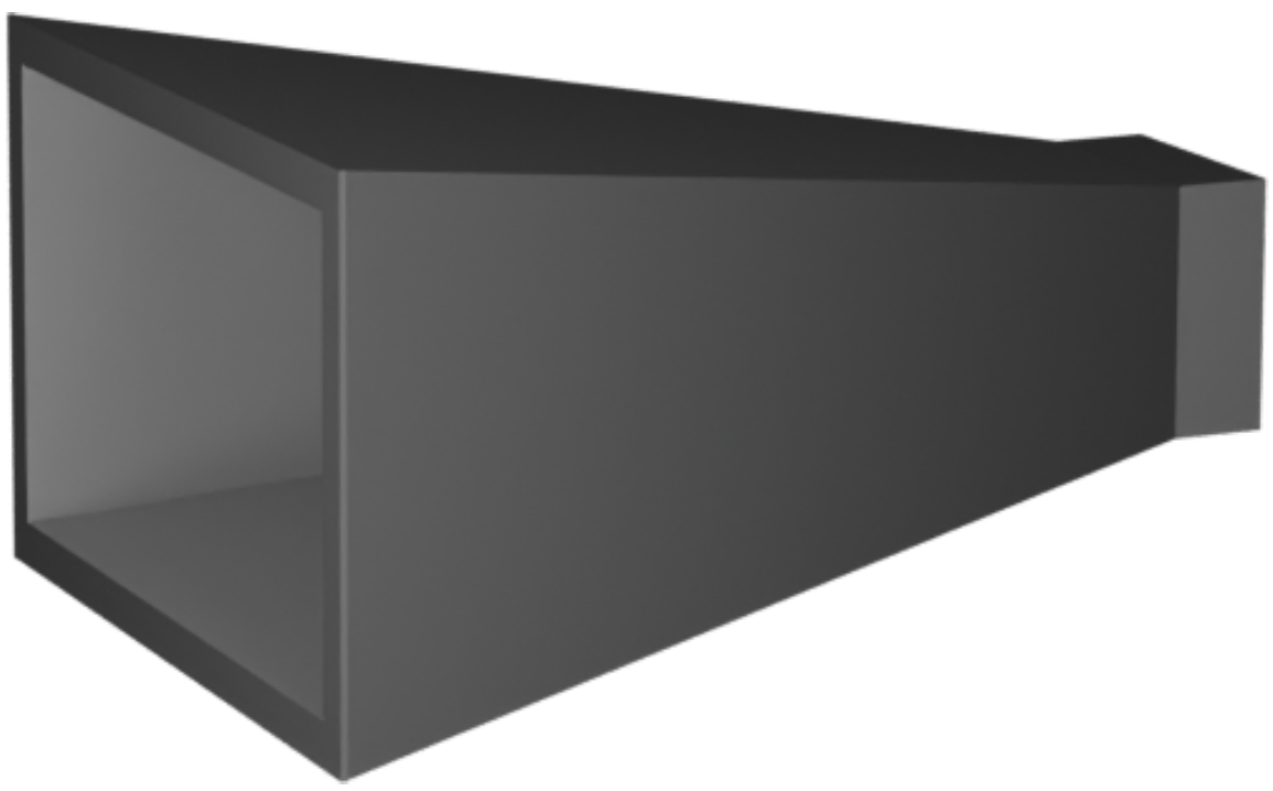
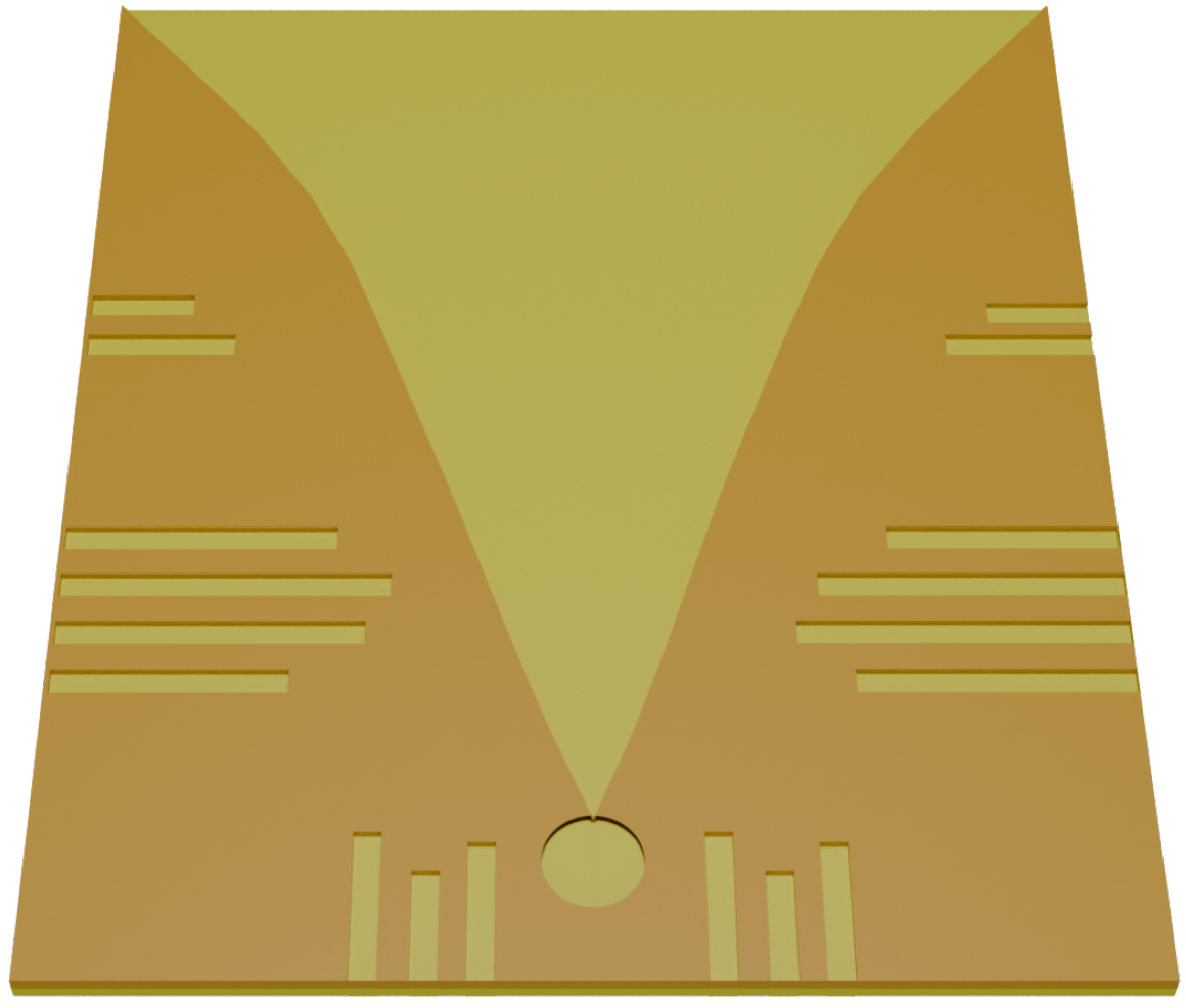
Horn antennas achieve a high gain and good efficiency through their pyramidal, conical, or sectoral structural design. These designs optimize the electromagnetic wave distribution, making them directional antennas [32]. One representation of a pyramidal horn antenna is illustrated in Figure 6. The main disadvantage of these antennas is their size and weight, which makes integration in drones a challenge. To address this issue, several approaches have been implemented to reduce their size and weight. For instance, some horn antennas use lightweight Copper Clad Laminate materials to replace metal components while keeping a high efficiency and cutting down both product expenses and weight [33,34]. When it comes to Wireless Power Transfer (WPT) in UAVs, the corrugated horn antenna achieves better impedance matching capabilities with less interference, so power transmission becomes more efficient [35].
Vivaldi antennas, as illustrated in Figure 7, are wideband antennas with a unique tapered slot design that helps them cover a broad range of frequencies efficiently [36,37]. The way the slot expands ensures consistent radiation and minimizes signal loss. Plus, these antennas are printed, which allows them to be integrated into small devices [38]. Because of these features, Vivaldi antennas are especially useful in UAVs, where versatility and limited space are key, though designing them correctly is essential for getting the best performance. In [39], two custom-designed Vivaldi antennas were developed to optimize performance in UAV systems. The larger Vivaldi antenna stood out for its directivity and stable phase center, which helped improved the detection accuracy and enhance the signal-to-clutter ratio. On the other hand, the smaller Vivaldi provided a more compact and lightweight antenna, even though it introduced some phase variation. The two Vivaldi antennas were made to enhance size, weight, and performance trade-offs while keeping bandwidth and radiation characteristics.
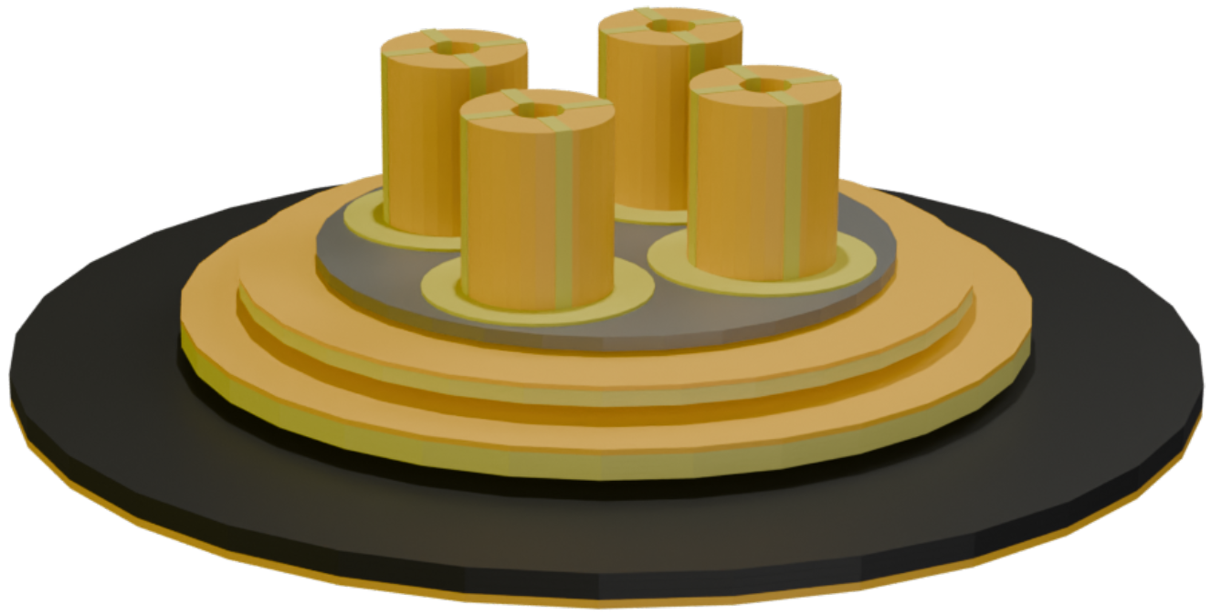
The DR antenna is a microwave antenna that uses resonant dielectric materials to generate electromagnetic radiation. It confines the radiated wave through a sharp transition from a high-dielectric constant to air. This technology is prefered at higher frequencies because it eliminates the need for conductive elements in the transmission path, thus reducing associated losses. The advantages of using DR antennas is their flexible design; they can be made in various shapes, such as cylindrical or rectangular, and are low-profile antennas with high radiation efficiency [40]. In [8], the DR was used because of its compact size, which facilitated integration into UAVs but also improved polarization by changing the feeding structure and using vertical choke rings to suppress back-lobe radiation and multipath effects. This antenna is illustrated in Figure 8.
To further analyze these antennas, Table 3 presents a side-by-side comparison of horns, vivaldis, and DR antennas mentioned above.
Horn antennas are known for their directive radiation pattern and, according to Table 3, the gains of [33,35] exceeded 15 dBi, which made them consistent with theoretical expectations. In terms of bandwidth, both antennas in [33,34] had a WB and, while it is mentioned in [34], a value is not presented. When it comes to frequency, in [33], 5.4 GHz was used because the radar payload was powered by the Ettus Universal Software Radio Peripheral (USRP) E312, which only supports frequencies up to 6 GHz. Horns also achieve a good balance between penetration and spatial resolution, making this frequency well-suited for monitoring. The European Space Agency (ESA) uses this frequency for crustal deformation monitoring, which validates its effectiveness in applications [33,34].
The two vivaldis in [39] also had a WB that went from 600 MHz to 3 GHz. In Ground-Penetrating Radar (GPR) scenarios, there is a trade-off that has to be considered between penetration and resolution, i.e., lower frequencies can penetrate deeper but have lower resolution, while higher frequencies have higher resolution but less penetration depth. Since this antenna was designed for landmine and IED detection, the authors chose a maximum frequency of 3 GHz because if the frequency was higher, this would have resulted in poor ground penetration, so that is why they limited the operating band to this value.
The DR operates in two main frequency bands: L5/E5a with a central frequency of 1176 MHz and L1/E1 with a central frequency of 1575 MHz. These frequency bands belong to the Global Navigation Satellite System (GNSS) spectrum and are usually used for UAV navigation. The 1176 MHz, which corresponds to the L5/E5a frequency band, provides better accuracy and resistance to multipath interference due to its higher chipping rate and advanced error correction, which is crucial for precise DF in complex environments. In contrast, the 1575 MHz, which belongs to the L1/E1 frequency band, is widely used for its broad satellite coverage, signal availability, and compatibility with most GNSS receivers; even if it is more prone to multipath effects, it remains essential for global coverage and long-range navigation [41]. The gain of this antenna is very low, −1 dBi in both bands due to the inter-mode coupling in the quadrifilar feed of the antenna; in other words, a significant part of the power is reabsorbed by the opposite feed-strip and, because of that, it is not radiated [8].

2.4. Microstrip Patch

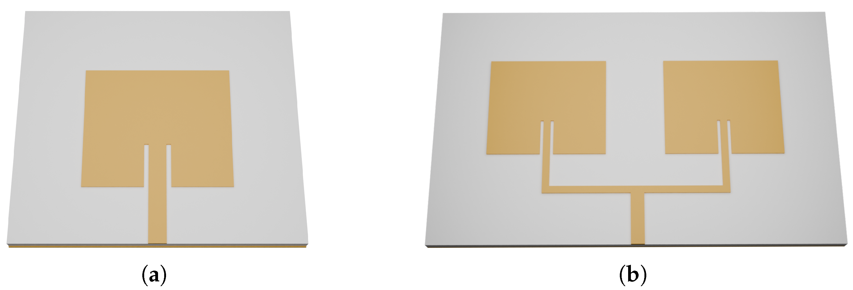
A microstrip patch is an antenna with a flat conductive element placed on top of a dielectric substrate, above a ground plane. Patch antennas can be designed in various shapes, like rectangular, circular, or in other geometrical patterns, so they can meet different operational requirements. Figure 9a illustrates a typical patch antenna, highlighting the planar and simple structure.
Even though they are simple, lightweight, low-cost, and easy to manufacture, patches typically have limited bandwidth, gain, coverage, and polarization flexibility. So, in order to solve these issues, various modifications and design approaches are implemented to enhance their performance [42]. Several studies have suggested different patch antenna designs for UAVs, addressing specific challenges. The implementation of conformal patch antennas allows these antennas to adapt to the drone structure to improve aerodynamic performance, as opposed to standard antennas, which are typically flat and not flexible, which limits their ability to integrate smoothly with curved surfaces [6,43]. Another antenna design solution is transparent antennas. This design can be integrated with solar cells, enabling energy harvesting to extend UAV flight time while also allowing direct communication with satellites [44,45]. Another approach involves reconfigurable patch antennas, which use adaptive feeding networks to switch between linear and circular polarization, increasing resistance to interference and improving communication stability [46]. While individual patch antennas provide compact and lightweight solutions for UAVs, they often suffer from limited gain. To address that, patch antenna arrays, as shown in Figure 9b, where a 2 × 1 array configuration is presented, are frequently implemented, improving directivity and gain. These aspects are presented in the following Table 4 and Table 5, while the performance advantages of the array configuration will be discussed in a later section.
In Table 4 and Table 5, we can see that the majority of the antennas are arrays. This is because arrays achieve a much better gain compared to patches, which enhances directivity and results in improved signal focusing. Most microstrip antennas, whether single patches or arrays, include a ground plane beneath the substrate, which tend to suppress back radiation and reinforce this directive behavior. However, there are exceptions, like in [9,47,48], where the radiation patterns deviate from directional to omnidirectional. In [48], the omnidirectional radiation pattern occurred because of the patch design. The central disk of the patch generated vertical electric fields, while the dual-spiral part of the patch generated horizontal electric fields, which made them resonate in a quadrature-phase difference, resulting in the omnidirectional radiation pattern. In [9], the quasi-omnidirectional radiation pattern came from the excitation of the parasitic patches, which created grating lobes, which improved coverage at low elevation angles. Although, the authors of [47] did not justify why this radiation patterns occurred.
In terms of frequencies, choosing the right one depends on the requirements of the UAV’s application, so, to better organize the information gathered in Table 4 and Table 5, the frequencies were put in different categories: low frequencies between 300 MHz and 3 GHz, medium (mid) frequencies from 3 to 30 GHz, and high frequencies from 30 to 300 GHz. These names were chosen solely for organization purposes. Low frequencies are ideal for long-range communication [6,44,48,57] and penetrability, making them useful for some object detection applications and environmental and precise monitoring [9,14,46,58,61,63,70]. Mid frequencies provide a balance between propagation and data transmission, which is why they are also used for UAV communication [13,43,48,54,62] and obstacle avoidance [50,64,67]. These frequencies are also suitable for monitoring and surveillance [51,53,55,56,59,60]. High frequencies enable high-resolution and fast data transfer, making them essential for radar systems and collision avoidance [65,66,71].
Patches usually have a narrow bandwidth because of their design, and this is seen in [9,12,14,43,48,51,55,57,58,61,64,66,67,70,71]. However, to improve bandwidth, some studies modified the antennas by changing their structural design or using material-based techniques, as mentioned in Section 2. Some configurations achieved an MB [9,13,44,46,50,53,59,60,63,65,68], while two authors were able to obtain a WB [47,52]. One example on how to improve bandwidth is in [47], where an array with a tree-shaped fractal structure maximized space utilization while also allowing for broadband performance. The third-order fractal structure was used to improve impedance matching and increase the bandwidth. Another approach is using a stacking configuration. This is done by layering patches on top of one another [62]. One can also cut slots in the radiating element, as with the done in [7,52,53,67], and, by cutting these slots, the current flowing through the antenna is redistributed, which results in a better bandwidth performance.

3. Comparative Analysis

To compare the antennas mentioned in Section 2, this section examines four key factors that determine their suitability for UAVs, i.e., the type of antennas; the type of polarization achieved and their methods; the antennas’ size and weight limits as well as the frequency, bandwidth, and applications they are used for; and, finally, experimental validation, in other words, which prototypes have been fabricated and mounted on which UAVs. Each following subsection draws on the studies to show common design trends, inherent trade-offs, and persisting research gaps.

3.1. Type of Antennas

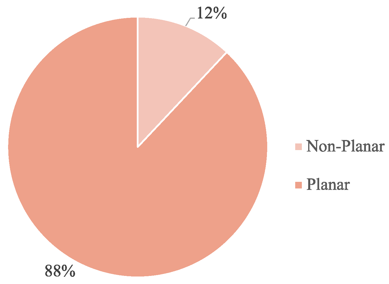
By comparing the different types of antennas described in Section 2.1, Section 2.2, Section 2.3 and Section 2.4, it is evident that most antennas for UAVs are planar, as observed in Figure 10, which shows the percentage of antennas that are planar versus non-planar. This planar configuration is prefered because of its low cost and low profile, which make them easy to integrate into drones [72].
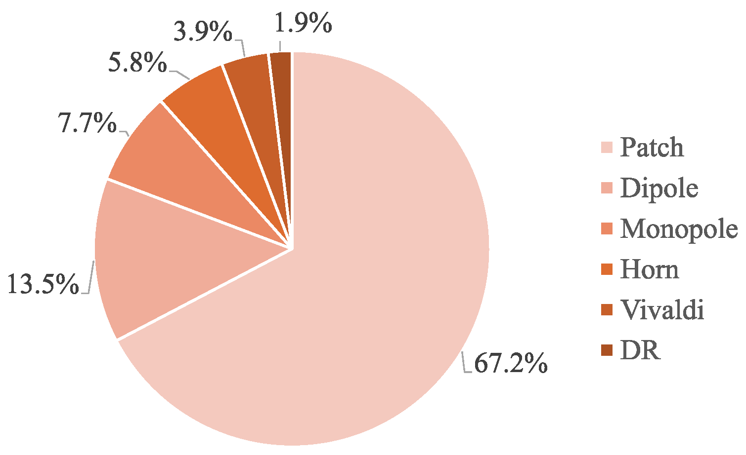
To visualize the distribution of the antenna types used in UAVs, a pie chart is presented in Figure 11. The data is based on the antennas shown in Table 1, Table 2, Table 3, Table 4 and Table 5. Figure 11 gives a clear overview of which antennas are mostly used in drones, highlighting the dominance of microstrip patch antennas, followed by dipoles and monopoles, while the rest of the antennas occupy a residual value of what is used. Inside the planar configuration, the majority of the antennas used are microstrip patch antennas. The antennas that changed their usual configurations, i.e., those that changed from wire to planar, were the dipoles shown in Table 1 and the monopoles shown in Table 2. Regarding the other types of antennas, the vivaldis, for instance, are not commonly used in UAVs because they are too large, which makes integration in drones difficult, while also causing air resistance when the drone is flying due to their design requiring a perpendicular alignment with the drone’s body. Horns, just like the vivaldis, also impose some limitations in terms of size and weight, which causes aerodynamic drag and limits the choices of drones to use.

3.2. Frequency, Bandwidth, and Applications

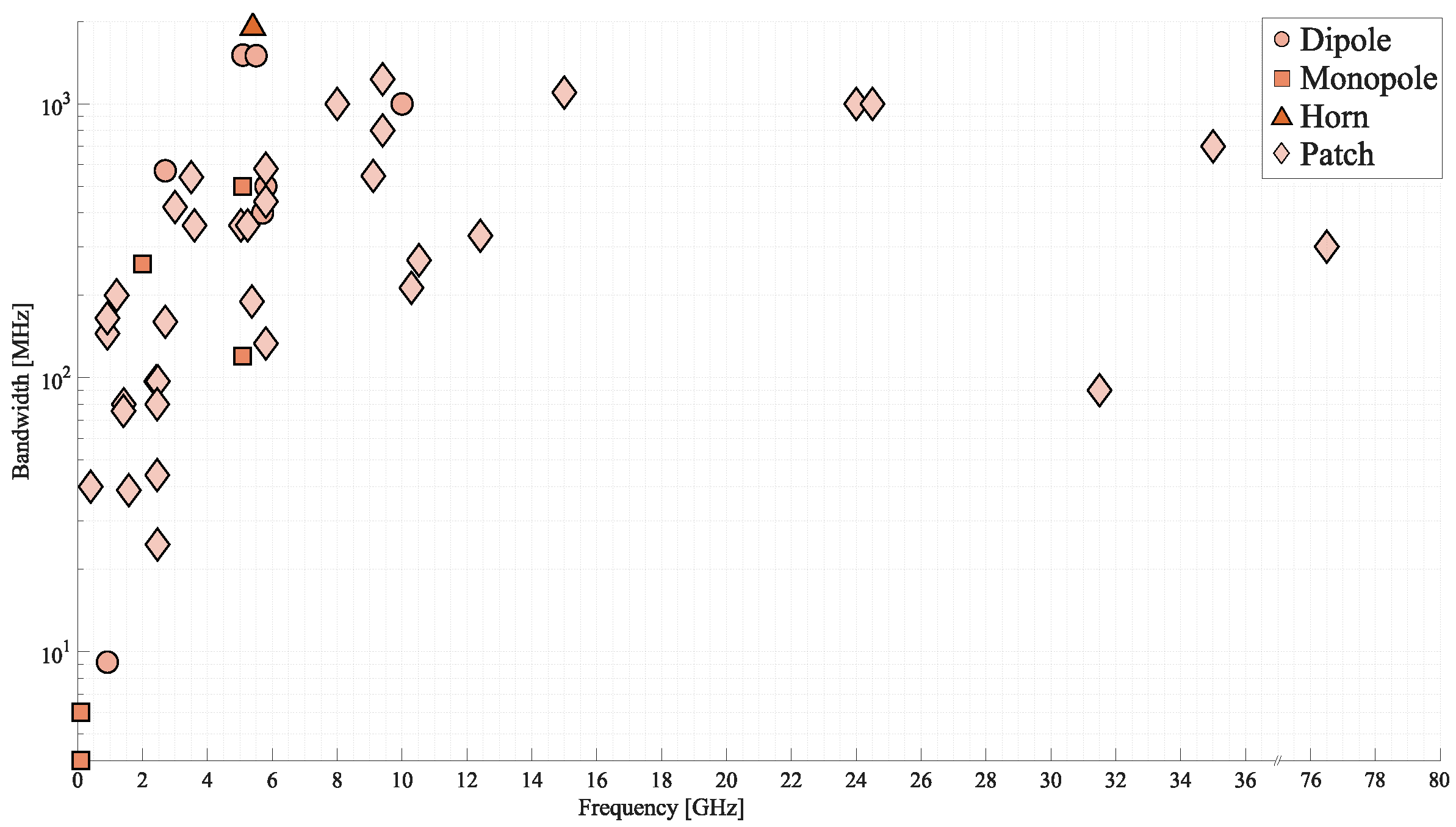
When it comes to frequency and bandwidth, Figure 12 shows a graph of bandwidth versus the center frequency of the antennas in Section 2 for the papers that specify both values. This data was taken from Table 1, Table 2, Table 3, Table 4 and Table 5. It is important to note that not every antenna appears on this graph because some authors do not report frequency or bandwidth information in their papers.
In Figure 12, the cloud of points reveals a cluster between 1 and 7 GHz, while a few designs appear above 10 GHz. This limited presence of antennas above 10 GHz can be attributed to several practical challenges; for example, at higher frequencies, common substrate materials exhibit more dielectric losses, which reduces radiation efficiency. Even though there are high performance substrates offering better characteristics at these frequencies, they are more expensive and complex to fabricate, making them less suitable for low-cost and lightweight antennas [11]. Additionally, millimeter-wave antennas require precise physical dimensions leading to tighter fabrication tolerances. Therefore, minor variations caused by mechanical vibrations, structural deformations, or temperature fluctuations can degrade their performance when mounted on UAVs [73]. Within this main cluster, dipoles, monopoles, and patches achieve bandwidths of roughly 50 to 600 MHz. This bandwidth contrast explains why patches are in the lower portion of the plot, while monopoles and dipoles spread across a more wider band, visible in Figure 12.
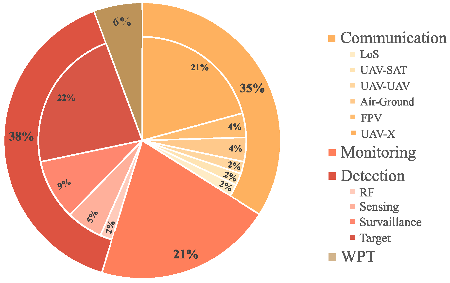
In terms of applications, given the Tables from Section 2, most antennas designed for UAVs fall into two broad application classes: detection and communication. Detection covers tasks such as target recognition and sensing, whereas communication encompasses air-to-ground, drone-to-drone, and drone-to-satellite links. Monitoring represents a meaningful fraction of the antennas that were analyzed, and WPT has fewer antennas for this type of application. Figure 13 illustrates this distribution. Detection clearly dominates, with communication close behind. Antennas intended for monitoring form a noticeable portion, but have a smaller share, while those developed for WPT are comparatively rare, which is consistent with the still-emerging status of that field.
As mentioned earlier, the majority of designs fall within the 1 to 7 GHz interval ISM sub-bands that underpin UAV communication links. The same range also encompasses the L and S band radar frequencies used for detection tasks, so the spectral clustering in Figure 12 is consistent with the priorities of communication and detection highlighted in Figure 13.

3.3. Polarization

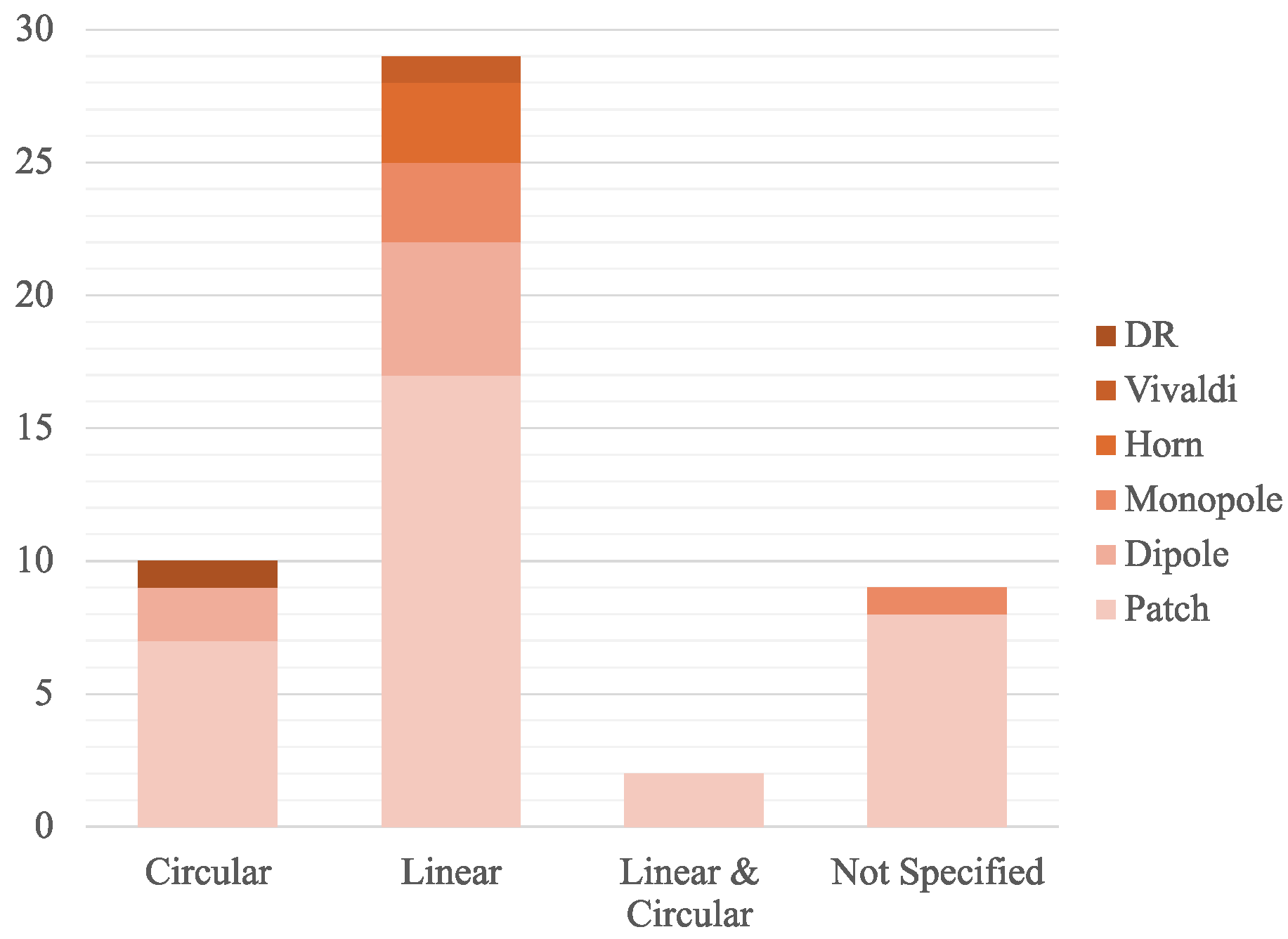
Polarization is also an important property of electromagnetic waves, and it is defined by the direction of the field vector over time. According to [24], polarization can be classified into three types: linear, circular, and elliptical [24]. When it comes to antennas for drones, linear and circular polarization are the most commonly used, as seen in the Tables of Section 3 because of their advantages in specific scenarios and applications. Figure 14 summarizes how many antennas adopt each type of polarization.
Linear polarization occurs when the electric field of an electromagnetic wave oscillates in a specific direction, which is perpendicular to the direction the wave is traveling. This polarization works well in systems where the orientation of the transmitting and receiving antennas is known. This type of polarization is naturally produced due to antennas’ design, such as dipoles, monopoles, and microstrip patch antennas. It is simple, efficient, and commonly used in sensing, object detection, and radar applications [6,12,19,20,28,62]. While the design of antennas ensures the generation of linear polarization, these studies go further, demonstrating how adjustments to the polarization angles, either mechanically or through feeding systems, can improve coverage and versatility in different applications; for instance, in [19,28], it was demonstrated how linear polarization can be applied to cover different areas. In [28], the system included a monopole and a circular patch antenna, creating a multi antenna system. The monopole generated vertical linear polarization, while the patch antenna used two feeding ports, phased at 90°, to produce two tilted polarization modes at −45° and +45°. Switches in the feeding system were used to control these tilted modes, allowing the antenna to choose which direction to cover. Similarly, [19] describes a bow-tie dipole with phase shifters and switches in its feeding system. This setup enabled four polarization modes: horizontal (0°), vertical (90°), and tilted (45° and 135°), to cover different areas. Linear polarization also enhances gain and directivity [6,12,20,62]. In [20], the antennas were mechanically positioned at a 45° angle, resulting in both vertical and horizontal polarizations. The main limitation of linear polarization is its sensitivity to alignment since the antenna’s orientation changes in dynamic environments, which can result in signal degradation [17].
On the other hand, circular polarization occurs when the electric field vector of an electromagnetic wave rotates continuously in a circular path as the wave propagates. This is achieved by generating two orthogonal electric field components of equal magnitude with a 90° phase shift. Depending on the direction of rotation, this can result in RHCP or LHCP [24]. This can be achieved through specific design techniques and feeding networks. In patch antennas, one method involves modifying the physical structure by trimming the upper-right and lower-left corners of a square patch, and RHCP is generated. On the other hand, trimming the opposite corners produces LHCP [57]. Other methods envolve cutting thin slots along a square patch and feeding diagonally [24]. Similarly, Cloverleaf antennas achieve CP by bending their wires at specific angles to create the required phase shifts [10]. When the feed network is used, an approach to achieving CP involves hybrid couplers and phase shifters. In [46], a reconfigurable feeding network that combined 90° and 180° hybrid couplers was made to achieve both LHCP and RHCP, while, in [8], the authors used hybrid couplers to create phase shifts that produced RHCP signals while suppressing LHCP signals. Another approach modifies transmission lines within the feeding network to introduce the phase shifts. In [13], a microstrip patch array was explored where bending microstrip lines in the feeding system created phase differences between signals, enabling CP while maintaining design simplicity and efficient power distribution. The authors of [17,46] described a system using a branch-line coupler to connect four V-inverted antennas, and these feed networks also included switches to select the polarization, with [46] switching between RHCP, LHCP, and linear polarization modes, while [17] switched between LHCP and RHCP. Circular polarization also enhances antenna performance by improving coverage and adaptability. It allows for dynamic switching between RHCP and LHCP, making it especially effective in environments where signal alignment and reflections are significant challenges. For example, GNSS satellites typically use RHCP polarization, so when the goal is to communicate with them, the receiver antenna should have the same orientation to minimize signal losses and enhance efficiency. In other words, if the receiver is a linearly polarized antenna, it will suffer from an inherent 3 dB loss from polarization mismatch, so, to ensure optimal performance, the receiver antenna should also employ RHCP, and this is why [8,57] focused on achieving RHCP.

3.4. Size and Weight

Another important thing to have in consideration is the weight of the antenna. Drones have different sizes and support different weights. The main problem is that most authors do not report this parameter, which is why the tables from Section 3 do not show this information. Nevertheless, the few studies that did provide the antenna weights data are shown in Table 6.
Comparing the data from Table 6 shows that planar antennas are more lighweight compared to other types. For instance, microstrip patch antennas and meander lines weighed around 19.2 g and 66 g [28,53], whereas two vivaldis and horn antennas weighed 150 g, 130 g, and 495 g, respectively. It has to be taken into consideration that in [33,34], the drone carried two horns, so the combined weight of the system was 900 g. The two vivaldis in [39] varied in weight because of their size, which can be seen by the value of the smaller version being less. Also, despite the use of lightweight materials, the horns continued to remain substantially heavier than the vivaldis and the other microstrip antennas. Meanwhile, Refs. [14,44] do not report the weight of the antennas but report the weight of the whole system. In [44], the system included the antenna and the structure of the solar cells, while, in [14], it says that the weight of the system did not surpass the 1000 g. Out of the 50 reviewed papers, only 7 reported antenna weight, highlighting a common gap in the UAV antenna literature. While electrical performance is often prioritized, physical constraints like weight are critical for real-world UAV applications, meaning that future studies should aim to include such data to improve practical relevance. Overall, planar antennas are more lightweight and compact, with microstrip patch antennas being lighter and compact, followed by vivaldis and, finally, horns, which remain heavy and less compact despite the use of lightweight materials. So, the selection of antennas for UAVs depends on their application, the size of the UAV, and how much they can support.

3.5. Fabricated Antennas, Used UAVs, and Applications

Out of all the antennas mentioned in Table 1, Table 2, Table 3, Table 4 and Table 5, every single one was simulated. Among them, those who were fabricated, analyzed, and tested in a controlled environment, i.e., tested in an anechoic chamber or tested outdoors, are presented in Table 7.
While these antennas were specifically designed for drones, very few authors provide details about the type of drone these antennas are for; the majority makes no reference to which model or what size the UAV is, but there are authors that do provide some information on the matter and give visual clues in their images or descriptions. For instance, [8,17,33,34] used a hexacopter, with both [33,34] using the DJI Matrice 600 Pro, while [8,17] did not mention the model. In [19,30,39,50,58,60], the images provided show a quadcopter. Only in [39,60] are the models mentioned, which are the DJI M200 and DJI Spreading Wings S1000+, respectively. The authors in [43,69] mention that their antenna is designed for multi-rotor UAVs, but they do not provide more information, and the authors in [9,53,59,67] state that the antenna is suitable for fixed-wing UAVs, but, once again, do not mention the model of the drone. In [71], a DJI S1000 octocopter is used, while, in [14], the author works with agro-drones. Finally, [52] mentions that their antenna is for a small drone and [7], using a dual-copter measuring 18.50 × 9 cm.

4. Miniaturization Techniques

Miniaturization techniques are mostly used to reduce an antenna’s physical size without sacrificing performance, as smaller designs usually do. This can be achieved by either modifying the antenna’s physical structure or electromagnetic properties [11]. The following Section 4.1 and Section 4.2, explore these approaches in more detail.

4.1. Techniques That Modify Antennas’ Physical Structure

When it comes to antennas’ physical structure, different techniques can be used to make them more compact without affecting their performance. These techniques focus on modifying the geometry of the radiating element to maintain the desired electrical length while reducing the overall dimensions. The most common methods include the use of meander lines and fractal geometries, as well as slots and slits to enhance the antenna characteristics.
Meander lines and fractal antennas are both based on space-filling curves and are designed to maintain antenna dimensions without altering electromagnetic properties. While meander lines achieve their design by folding a straight line into zigzag patterns, fractal antennas use self-similar geometries, such as snowflakes, trees, and ferns [11]. In [28,29], both demonstrate the use of meander lines to reduce the antenna’s size. In [47,51], a tree-shaped and a reconfigurable snowflake fractal antenna for 5G and satellite communication and radar systems, respectively, also helped reduce the antenna’s size. Figure 15 shows an illustration of both a fractal and a meander line antenna.
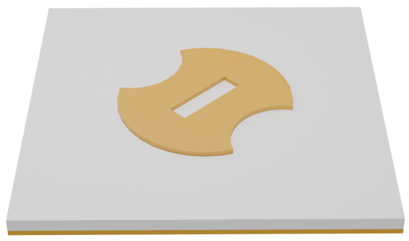
Slots and slits are holes that are normally made on the radiating element, as is seen in Figure 16, and their main objective is to modify and enhance the electromagnetic properties of antennas. Even though these structural cuts are primarily meant to improve electromagnetic properties, they also lead to the reduction of the antenna’s physical structure. This is usually a secondary effect, but articles like [13,30] mention it. These structural modifications have been used to increase the bandwidth [52,53], optimize radiation patterns [43,53,54], improve gain [30,52,54,55], enable dual-band operation [43,55], and create circular polarization [56,57,58]. In addition to being performed on the radiating element, creating slots and slits can also be performed on the ground plane, improving the antenna’s performance by enhancing bandwidth and gain [7], optimizing power distribution within the antenna [13], and helping achieve circular polarization [8,13].

4.2. Material-Based Techniques That Change the Electromagnetic Properties of an Antenna

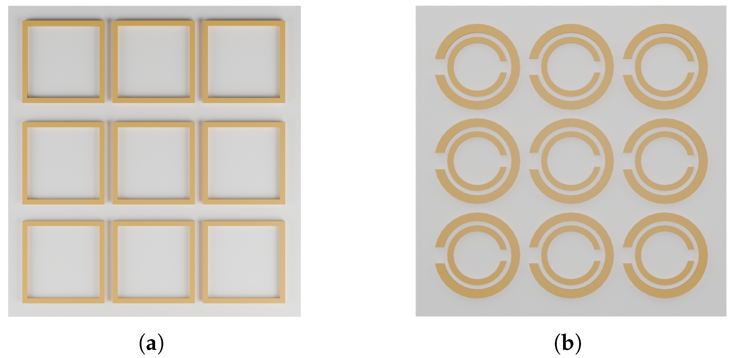
Another approach to achieve miniaturization in an antenna is by modifying its electromagnetic properties with materials and structural layering. These techniques focus on altering wave propagation and impedance characteristics, which include high-dielectric constant substrates, vertical stacking, and the integration of metasurfaces to enhance the antenna’s overall efficiency. Higher dielectric constant materials for substrates slow the propagation of waves, which leads to a reduction in the resonant frequency [11], resulting in more compact antennas [8,19,60], which helps reduce aerodynamic drag [19] and makes the antenna lighter [8,61]. Vertical stacking involves layering patches or substrates, as shoen in Figure 17 which improves the antenna’s performance while maintaining a compact design [11].
In [14,62,63], it was demonstrated that stacking microstrip patches improves antennas’ bandwidth and gain and that they can operate in multiple frequency bands while avoiding interference between them [63]. Meanwhile, layering substrates not only it enhances bandwidth [64] but also enhances signal quality and helps minimize interference because it efficiently separates high from low frequency signals [59]. In [48,53], circular polarization and dual-band operation was achieved, while, in [65], stacking was used to suppress sidelobes. Overall, vertical stacking boosts gain [44,62,63], bandwidth [59,62], multiband operation [14,63], and compact integration [44,60]. Another technique is using metasurfaces. In [7], coffee bean-shaped metasurfaces improved gain and radiation efficiency and reduced losses of the antenna, while, in [23], the Frequency Selective Surfaces (FSSs), shown in Figure 18a, improved gain and enhanced beamforming, i.e., helped reduce the beamwidth of the main lobe. In [49], stacked metasurfaces with unequal spacing helped optimize circular polarization and bandwidth. All of these techniques improve different antenna properties while maintaining a compact design, which contributes to antenna miniaturization.
The reviewed works propose several structural and material-based techniques to reduce the size and improve the performance of antennas for UAV applications. These techniques presented in Section 4 focus on how each approach contributes to antenna miniaturization. These strategies are summarized and the main benefits associated with each technique, as described in the cited literature, are highlighted in Table 8.

5. Multi-Antenna Systems

Beamforming is a technique in antenna systems that allows the control of electromagnetic waves to enhance the quality of the signal and the efficiency of communications. This section categorizes beamforming, including beam-switching, beam-steering, beam-scanning, and the use of arrays, each with distinct methods to control the direction of the signal.

5.1. Beam-Switching

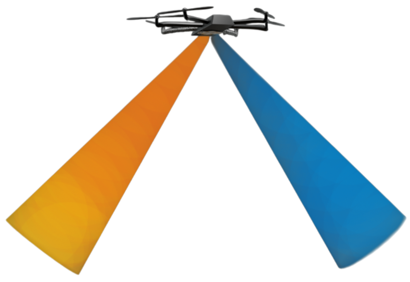
Beam-switching is a widely used technique in communication systems to redirect antenna beams in a discrete manner, enabling coverage in different directions, as represented in Figure 19, where the system can choose between the orange beam and the blue beam.
In some approaches, this technique is implemented using switching networks controlled by microcontrollers, which activate individual antennas or groups of antennas to direct the beam. For instance, [17] uses five fixed antennas positioned at different angles. A microcontroller manages the switches, which are controlled via Bluetooth through an application, allowing the UAV to dynamically redirect the beam to cover different areas around it. Similarly, in [20], the beam-switching system enables 360° coverage around the UAV, where antennas can be activated individually or together. This setup not only optimizes coverage but also allows for polarization selection. In [43], beam-switching is employed to improve communication coverage between the UAV and a ground station. The system utilizes directional beams, with only one antenna being active at a time. Although it does not detail the control mechanism, the system ensures reliable connection across multiple regions. In [51], a system is described where the antenna array can switch between three modes, Uniform Linear Array (ULA), Uniform Circular Array (UCA), and Uniform Rectangular Array (URA), by activating specific ports. Each patch antenna in the array is fed individually, but the method for selecting these modes is not explicitly mentioned. Another common approach for implementing beam-switching in antenna systems involves the use of PIN diodes. In [27], the HPERs equipped with PIN diodes allow the beam to switch between eight predefined directions: 0°, 45°, 90°, 135°, 180°, 225°, 70°, and 315°. When a diode is active, the corresponding parasitic element acts as a reflector, redirecting the beam to the opposite direction. Figure 20 shows an image of how the PIN diodes are integrated with the HPERs. Similarly, in [22], PIN diodes are integrated into metasurfaces made of split-ring resonator (SRR) cells. An example of a SRR surface can be seen in Figure 18b.
When the diodes are activated, i.e., when they are turned on, the metasurface reflects the incoming waves; when they are deactivated, i.e., when they are turned off, the metasurface becomes transparent, allowing the waves to pass through. This enables dynamic beam direction adjustments based on the state of the diodes. The authors in [56] combined PIN diodes with phase shifters to modify the feeding phases, thereby redirecting the antenna beam. Although the exact control mechanism is not described, this configuration highlights the versatility of PIN diodes in achieving beam reconfiguration. Reconfigurable feeding networks also offer methods for implementing beam-switching. In [19], the author describes a feeding network composed of switches, Wilkinson power dividers, and transmission lines with phase delay. This configuration enables beam redirection at angles of 0°, 45°, 90°, and 135°. The switches select the active antennas or antenna groups, but the control details are not provided. Similarly, in [28], a feeding network based on a Grounded Coplanar Waveguide (GCPW) was used, which included a 90° hybrid coupler, phase delay lines, and switches. This setup adjusted the power and phase distribution between the monopole and circular patch antennas, allowing the system to operate in four different beam modes.
While many of the reviewed articles do not provide detailed descriptions of the control mechanisms for beam-switching, they demonstrate the effectiveness of the technique in enhancing UAV communication. For instance, in [22,27], the application of voltages to diodes is briefly mentioned, but the specific implementation of control systems is not detailed. In [43,56], the importance of directional beams is highlighted, but the authors omit information about how switching or phase control is achieved.
In [28], a monopole and a patch antenna were used. The monopole exhibited an omnidirectional radiation pattern, while the patch had a directive radiation pattern. By combining both radiation patterns, the multi-antenna system achieved a wider coverage for UAV applications. This system used a beam-combining technique, where the feeding network, consisting of a hybrid coupler, a phase delay, line and a switch, controlled signal distribution and adjusted the phase. This enabled beam reconfiguration, allowing for directional adaptability and enhanced communication performance.

5.2. Beam-Steering

Beam-steering is a technique used to manipulate the radiation pattern of antennas, enabling dynamic or semi-dynamic control of beam direction. These methods are essential in UAV communication systems, allowing flexible tracking and enhanced connectivity with ground stations or other UAVs.
In several systems, beam-steering is achieved by adjusting the phases of the feeding signals across antenna elements. In [57], the feed phases were optimized through simulations to achieve both beam-steering and null-steering. While the system manipulated the feeding phases, it did not support dynamic adjustment as the phases were fixed based on pre-determined combinations. Similarly, in [60], the beam direction was controlled by dynamically adjusting the phases across antenna elements using a reflection-based phase shifter architecture. This design employed a four-port branch-line coupler and reactive variable loads implemented with varactor diodes. However, like [57], the system relied on pre-simulated phase configurations, limiting its ability to adapt dynamically in real time. In [52], beam-steering was achieved by electrically controlling the phase difference at the input of each quadrant of the 2 × 2 antenna array. The phase shifters were used to create phase differences between the quadrants, allowing the beam direction to be adjusted across a 60° range in elevation and from −75° to 20° in the azimuth plane. Even though this system allowed for precise beam control, the phases were pre-configured and did not allow for fully dynamic real-time adjustments.
A combination of beam-steering and pseudo-conical scanning was implemented in [56], where the system adjusted the feeding phases of the antenna elements dynamically to alter the beam direction and cover different areas. The pseudo-conical scanning method manipulated the radiation beam using a central element and one of the surrounding elements, creating a pseudo-conical scanning pattern. Once again, the feeding phases were pre-defined and stored in a table, but the system was still flexible in directing the beam within these constraints.

5.3. Beam-Scanning

Beam-scanning systems are designed to dynamically track targets or adjust the beam direction in real time, making them ideal for UAV applications. In [12], beam-scanning was implemented to adjust the direction of the radiation beam in response to the UAV’s movement. The system used a pilot signal tracking method to determine the optimal beam direction. As the UAV changed direction, the main lobe of the radiation pattern was adjusted accordingly; however, the article does not detail the hardware or algorithm used to achieve this real-time tracking.

5.4. Metasurfaces

Metasurfaces are structures that are artificially engineered; they are composed of subwavelength unit cells that manipulate electromagnetic waves in a controlled manner. These structures allow for wavefront shaping, polarization control, and beam-steering without requiring complex phase-shifting networks or mechanically moving parts. In this context, the focus is on their ability to achieve beamforming.
In [49], a Phase Gradient Metasurface (PGS) was used to achieve beamforming. The PGS gradually modified the phase distribution of incident waves, allowing for a controlled beam redirection. The metasurface was placed in a λ /4 distance above the main antenna, introducing phase shifts across different parts of the wavefront. The study presented three different PGS designs, each with specific phase differences of 30°, 45°, and 80° between unit cells. These configurations allowed the beam to be tilted at 20°, 30°, and 60°, respectively. This technique did not allow for dynamic beamforming.
In [44], even though the main purpose of the metasurface with unequal spacing unit cells was to achieve circular polarization, it also helped with the direction of the beam. The metasurface, through its structured unit cell distribution, modified the phase of the radiated waves, contributing to a more directional radiation pattern with high gain. Even though the paper does not explicitly state a shift in the beam angle, it does indicate that the metasurface influenced the radiation characteristics, ensuring that the energy was more concentrated.

5.5. Array

Arrays have been developed to enhance gain, bandwidth, and directivity in UAV communication and radar applications. For airborne line of sight (LoS) communication, a high-gain narrow-beam configuration and a stacked microstrip structure improved data transmission efficiency [62]. In UAV radar systems, gain enhancement is achieved by combining E-shaped slots, a structured feeding network, and rectangular slots, which together improve dual-band operation and suppress sidelobes to enhance detection accuracy [55,67].
For drone detection and collision avoidance, patch antennas help focus signals, while hybrid feeding techniques and careful antenna spacing keep transmission and reception separate, reducing interference and improving radar accuracy [64,68]. In 5G-based drone networks, using multiple frequencies and adjusting antenna placement enhances directivity, making target detection more effective [50].
Multi-band arrays have been designed for high-resolution Synthetic Aperture Radar (SAR) imaging using layered patch structures [63] and for precise remote sensing by integrating L- and Ka-band antennas, enabling accurate soil moisture and salinity measurements [70]. Compact filters and optimized structures further enhance soil and temperature monitoring from UAVs [14]. For UAV communication, metasurface structures and optimized slot designs increase bandwidth, gain, and radiation efficiency, ensuring broad frequency coverage and supporting high-data-rate transmissions [7]. The FSS and parasitic structures improve impedance matching and beam control, optimizing the scanning range for efficient UAV communication [23]. Beyond communication and radar applications, arrays have also been applied in UAV-based search and rescue. A monopulse antenna system enhances the estimation of the direction of the arrival of radio signals, improving detection accuracy for locating avalanche victims [58].
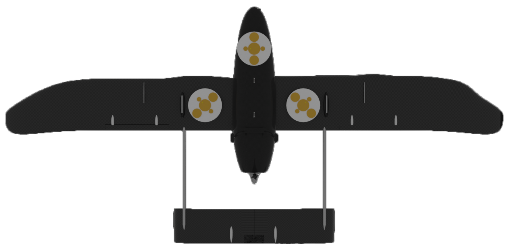
The authors in [9] presented a Multiple-Input Multiple-Output (MIMO) antenna system for UAV applications that used a dual-mode circular patch antenna.
Even though multiple antennas are usually used to shape the radiation pattern by adjusting phase and amplitude, this system achieved radiation pattern diversity by exciting different modes within a single antenna and integrating multiple antennas in a triangular configuration. The three antennas were arranged in a equilaterel triangle shape, each with a specific orientation to enhance radiation coverage. Two of them were rotated clockwise and counterclockwise relative to the third antenna, creating a setup that ensured low mutual coupling and stable performance across different frequency bands. This approach enabled wider coverage and improved communication reliability across various orientations. This MIMO antenna system is shown in Figure 21.
In [8], a GNSS antenna array was designed for UAV navigation, utilizing multiple antennas to create a controlled radiation pattern. The array improved robustness against interference and multipath effects by allowing signal processing techniques such as null-steering, where interfering signals are suppressed by introducing nulls in the radiation pattern. This multi-antenna setup can be considered a form of beamforming as it enables directional control of the received signals, optimizing reception and enhancing positioning accuracy in challenging environments.

6. Discussion

Since most antennas used in UAVs are planar, as shown in Figure 10, choosing the right substrate is important. This is because the substrate influences the antenna’s electromagnetic performance; therefore, selecting the right one is essential to ensure good performance, especially when using miniaturization techniques to meet the size and weight requirements of UAVs. In Table 1, Table 2, Table 3 and Table 4, the most commonly used substrates are FR-4 and the Rogers family. The choice basically depends on the frequency range, cost, and application.
FR-4 is mostly used because it is low-cost and easy to acquire [74]. This substrate is also suitable for low and mid frequencies, but the lower the frequencies, the better; this is because for higher frequencies, the dielectric losses are bigger as these lead to a higher loss tangent, which reduces the stability and efficiency of the antenna, and that is why it is not recommended for higher frequencies [75]. Another downside of this substrate is that its dielectric constant cannot be controlled; in other words, the constant can vary between 3.8 and 4.8, and manufacturers are unable to guarantee a consistent value across different batches. When it comes to the antennas that use this substrate, presented in Table 1, Table 2, Table 3 and Table 4, they mostly operate between 915 MHz and 8 GHz, which aligns with [75]. In [64], a frequency of 24 GHz was used. Although this was still within the mid-frequency range, because this frequency approached higher values, the dielectric losses became more significant. To address this problem, [64] employed a stacked structure with FR-4 for lower frequencies and DC signals and Teflon for high-frequency signals. This configuration reduced the dielectric losses that are associated with FR-4 at 24 GHz.
The Rogers family substrates are also used due to their easy access and variety. The most commonly used are the Rogers RO3003 and Rogers RT Duroid 5880, given the information presented in the Tables from Section 3. For higher frequencies, the Rogers RO3003, Rogers RT Duroid 5880, and Rogers RO4830 are more commonly used due to having great stability at these frequencies. The Rogers RO3003 in [47,69,71] operated in this mmWave band; specifically, [47] focused on communications, while [69,71] addressed radar applications. The Rogers RT Duroid 5880 is used for frequencies above or equal to 10 GHz, that is, the mid to higher frequencies, as observed in the tables of Section 3. It is mainly used for radar [22,51,68] and wireless communication systems [62]. The main difference in these two substrates lies in their dielectric constant and loss tangent. The Rogers RT Duroid 5880 has a lower dielectric constant, resulting in a reduced loss tangent, which makes this substrate perform better compared to the Rogers RO3003. The drawback is that it is more expensive. The Rogers RO4830 is more price-sensitive, i.e., it is cheaper compared to the other Roger substrates mentioned because it has a higher dielectric constant, making it more susceptible to dielectric losses and less stable. It was used in [7].
The substrates with a high dielectric constant above 6.15 include the Rogers RO4360G2, Rogers RO6010, and Taconic RF-60. The Rogers RO4360G2 is made mainly for communication systems, which aligns with the application in [61], since precise vertical landing requires a reliable communication. Meanwhile, the Rogers RO6010 is used to help minimize the size of a circuit because it is ideal to operate at frequencies in the X-band or below and provides a good performance in multi-layer boards with reliable plated through-hole structures [8]. The Taconic RF-60 is for high-power RF and microwave applications and is designed to provide a better gain and efficiency in miniaturized antenna applications, as seen in [19].
Even though high-dielectric substrates are better for reducing the antenna size and making them more compact [76], they are more expensive and provide lower bandwidth and efficiency compared to low-dielectric substrates [11]. Of course, choosing the substrate also depends on the application and cost, which explains why the predominant substrates in Table 1, Table 2, Table 3 and Table 4 are those with lower dielectric constants.
In terms of polarization, linear polarization is the easiest to implement because it naturally occurs when feeding dipoles, monopoles, horns, vivaldis, and patches. It can also be implemented with other techniques, for instance, in [28], a Coplanar Waveguide (CPW) feeding network was employed, which confirmed linear polarization. It had high efficiency and worked well when the position of the transmitter and receiver was stable and known. It helped optimize the radiation pattern for different coverage needs [19], reduce interference [20], and maintain beam directivity, avoiding signal dispersion [22], making it useful for sensing, object detection, and radar systems. Its main disadvantage is that it is sensitive to misalignment, meaning that changes in the drone’s orientation can weaken the signal.
On the other hand, circular polarization is more effective in dynamic UAV situations when the drone is constantly changing its orientation as it helps to minimize the signal degradation caused by these shifts [10], reflections, and multipath interferences [8]. This makes it ideal for satellite communication, GNSS navigation, and UAV networks. Circular polarization is mainly achieved by modifying the feeding structure, using hybrid couplers and branch lines to generate RHCP or LHCP. This method provides a more stable connection, especially in UAV-to-ground and UAV-to-UAV communication, where the polarization of the receiving antenna may not be known [17,53,56,58,59]. It is also used when the transmission is known as circular, such as in communication with GNSS, 5G networks, and satellites, where the polarization is predetermined to ensure optimal signal reception. In these cases, the advantage of this polarization is not to mitigate an unknown transmission path but rather to ensure compatibility with a system that already employs circularly polarized signals [13,46,49,57]. Even though this type of polarization is more complex to design, it offers better resistance to signal problems caused by environmental conditions and orientation changes.
In regard to multi-antenna systems, when it comes to beam-switching, this technique is useful in systems that are required to switch between predefined directions. The use of switching networks controlled by either switches or PIN diodes allows antennas to be reoriented to different areas, ensuring different coverages, without the need of a mechanical adjustment. However, the main limitation is its reliance on discrete positions, i.e., fixed angles, which may not be sufficient for applications that require precise and continuous tracking. On the other hand, beam-steering techniques offer more dynamic control over the beam direction by adjusting the phases of the feeding signals. This approach helps adjust the beam in real time, even though, in most systems, the adjustments are pre-defined and not made in real time, but they are useful for UAVs operating in dynamic environments, such as UAV-to-UAV or UAV-to-ground station communications. The downside of this technique is that these systems can be complex, which might increase power consumption and the need for more computing power. Beam-scanning, in contrast, allows for the tracking of moving targets by adjusting a signal’s direction based on the UAV’s position or the monitored object. This technique is particularly useful in surveillance and remote sensing applications, where precision in tracking is essential. The main challenge is that implementing it in real time requires specialized hardware and advanced signal processing algorithms. The use of metasurfaces in beamforming represents an innovative approach because it allows for the manipulation of electromagnetic waves without the need for complex feeding systems. However, their ability to achieve dynamic beamforming is limited due to many systems using fixed phase configurations or pre-determined beam angles, which restricts real-time adaptation. Arrays are commonly used to improve performance by enhancing gain, bandwidth, and directivity. For UAV communication, high-gain narrow-beam configurations improve data transmission efficiency. Similarly, in radar applications, arrays with specific slot designs help detect targets more accurately. The use of multiple frequencies and optimized antenna placement in UAV networks further improves directivity and target detection. Even though array-based systems provide significant benefits in UAV communication and radar, their fixed configurations poses challenges for dynamic, real-time applications.

7. Emerging Trends and Future Directions

When it comes to the future of UAV antenna trends and directions, research is shifting towards smart systems that can adapt their beam shape, direction, frequency, or polarization in flight. These adaptive antennas keep the radio link working even when the drone turns quickly, flies behind obstacles, or meets interference. This shift is driven by persistent limitations observed in current UAV antenna designs. Although recent advances have improved UAV antenna performance, several limitations persist. For example, high-gain and directive antenna structures remain bulky and heavy, increasing aerodynamic drag and complicating their integration into compact UAVs. In beamforming systems, most designs rely on fixed or discretely switchable configurations using PIN diodes or mechanical switches, which lack real-time adaptability and reduce communication agility in dynamic or obstructed environments. These limitations directly motivate the pursuit of future antenna systems that are lightweight, reconfigurable, and structurally integrated, ideally based on conformal substrates or programmable metasurfaces to enhance adaptability, reduce drag, and enable agile beam-steering for advanced UAV missions [77].
Another thing is joining UAV antennas with 5G, 6G, and future sub-terahertz networks. Compact phased-array antennas that cover several bands (FR1, FR2, and the new D/E bands) can steer their beams fast enough to hold links between drones, satellites, and ground stations. Another important thing is that every gram matters in the air, so designers focus on very light and energy-efficient parts by using thin plastics, fine ceramics, and 3D-printed lattices, plus feeds that waste little power. Some new rectenna layouts can even harvest radio energy or share the same opening for both power transfer and data.
Recent developments in ESPAR antennas also show promise for compact and cost-effective beam-steering. In particular, varactor-loaded microstrip ESPARs, like the 3 × 3 design proposed by [78], achieve wide angular scanning of up to 75° on the E-plane while maintaining good bandwidth and gain. Similarly, SIW-based leaky-wave antennas have emerged as dual-functional platforms capable of both frequency scanning and fixed frequency electronic beam-steering. As shown in [79], these antennas support endfire radiation with high gain and are well suited for integrated sensing and communication (ISAC) tasks in intelligent transportation and V2I scenarios, where dynamic beam control is crucial. While originally targeted towards other applications, the characteristics of these type of antennas in terms of efficient beam-steering suggest strong potential for adaptation to UAV platforms.
Flexible and conformal antennas push this idea further. Curved, foldable, or stretchable versions made with textiles, ink-jet printing, or other additive methods fit tightly to the drone’s skin. This lets builders place large arrays along the fuselage or wings, giving wide scan angles with almost no extra drag. These antennas, particularly those built on polyimide and other flexible substrates, are emerging as key enablers for next-generation UAVs. By conforming seamlessly to curved structures, they minimize aerodynamic penalties while preserving high-performance radiation characteristics. Moreover, their inherent flexibility supports integration into morphing or foldable UAV architectures and their compatibility with reconfigurable or active metasurface technologies opens new pathways for adaptive beamforming and multi-band operation. This combination of mechanical compliance and electromagnetic versatility makes stretchable and conformal antennas a technology for the future of lightweight, robust, and intelligent UAV communication systems. Additionally, transparent antenna designs, such as those based on conductive films integrated with solar cells, offer a dual benefit of enabling communication while allowing energy harvesting. These solutions can extend flight time without sacrificing electromagnetic performance and are particularly promising for long-endurance drones and satellite-linked missions.
As drone swarms become common, communication inside the group is also becoming important. Researchers are studying mesh networks that organize themselves, share spectrum, and stay in touch even if one link fails. Important points include interference-aware beam control, low-overhead timing, and hardware small enough for very small airframes. Furthermore, the application of AI and machine learning techniques for automated design and optimization remains largely unexplored in UAV-specific antennas and represents a valuable direction for future interdisciplinary research.
Still, big challenges remain, like keeping antennas from coupling when everything is miniaturized, predicting radiation on complex drone bodies, passing tests under many spectrum rules, and making flexible or reconfigurable arrays cheaply on a large scale. Solving these issues is crucial for fully autonomous drone fleets with fast, reliable broadband links.

8. Conclusions

The integration of antennas in UAVs faces several challenges due to size, weight, and aerodynamic efficiency. Because the number of applications for drones is increasing, the focus on antenna miniaturization, polarization strategies, and beamforming techniques is becoming essential. These approaches allow for better antenna performance without compromising UAV operational constraints.
Among the different types of antennas, microstrip patch antennas and their arrays are the most commonly used in UAVs due to their light weight and low profile. Arrays in particular offer higher gain and improved directivity, making them ideal for communication and radar applications where focused signals and long-range transmission are required. Beamforming techniques improve the reliability of communication by directing signals, while miniaturization techniques, like using high-dielectric materials and design modifications such as meander lines and fractal shapes, help make the antenna more compact and efficient, which is suitable for UAVs. But, despite these advancements, there are still challenges in balancing antenna size, weight, and performance. For instance, most beamforming techniques rely on fixed beam angles and do not offer fully dynamic real-time control, which limits their adaptability in rapidly changing environments.
Looking forward, the evolution of UAV antennas requires innovative designs that not only are more lightweight and compact but also offer greater flexibility, achieve fully reconfigurable steering beams, and operate seamlessly across 5G, 6G, and sub-THz bands to keep links alive under maneuver or interference. The integration of emerging materials, like metasurfaces and advanced multi-antenna systems, will help to push the boundaries of UAV communication capabilities. Such advances will be decisive for large-scale autonomous drone fleets engaged in critical inspection, logistics, and emergency-response missions, where robust and high-throughput links are essential.

Author Contributions

Conceptualization, P.P. and D.A.; methodology, S.R., P.P. and D.A.; visualization, S.R. and D.A.; validation, P.P., D.A. and F.S.; writing—original draft preparation, S.R.; writing—review and editing, S.R., P.P. and D.A.; supervision, P.P. and D.A. All authors have read and agreed to the published version of the manuscript.

Funding

This work was funded by the Fundação para a Ciência e Tecnologia (FCT) through Fundo Social Europeu (FSE) and by Programa Operacional Regional do Centro under the PhD grant 2024.01919.BD. It was also funded by national funds through FCT—Fundação para a Ciência e a Tecnologia, I.P., under the project UIDB/50008/2020, and the DOI identifier 10.54499/UIDB/50008/2020, https://doi.org/10.54499/UIDB/50008/2020. It was also supported by the European Union/Next Generation EU through Programa de Recuperação e Resiliência (PRR) [project no. 11: New Space Portugal (02/C05-i01.01/2022.PC644936537-00000046)] under grant BI/No2024/00119.

Conflicts of Interest

The authors declare no conflicts of interest.

References

  1. Criollo, L.; Mena-Arciniega, C.; Xing, S. Classification, military applications, and opportunities of unmanned aerial vehicles. Aviation 2024, 28, 115–127. [Google Scholar] [CrossRef]
  2. Hall, O.; Wahab, I. The Use of Drones in the Spatial Social Sciences. Drones 2021, 5, 112. [Google Scholar] [CrossRef]
  3. Yafoz, A. Drones in Action: A Comprehensive Analysis of Drone-Based Monitoring Technologies. Data Metadata 2024, 3, 364. [Google Scholar] [CrossRef]
  4. Mahfuz, M.M.H.; Park, C.W. Review of Patch Antennas used in Drone Applications. IEEE Access 2023, 11, 58367–58388. [Google Scholar] [CrossRef]
  5. Fixed Wing UAV Drone Free 3D Model. Available online: https://www.cgtrader.com/items/4453704/download-page (accessed on 29 June 2025).
  6. Vallikannu, R.; Sankar, P.; Kavitha, B.; Vinoth, M. Flexible And Improved Antennae For Drone Applications. In Proceedings of the 2024 Third International Conference on Electrical, Electronics, Information and Communication Technologies (ICEEICT), Trichirappalli, India, 24–26 July 2024; IEEE: Piscataway, NJ, USA, 2024; pp. 1–5. [Google Scholar] [CrossRef]
  7. Saeidi, T.; Saleh, S.; Timmons, N.; Al-Gburi, A.J.A.; Karamzadeh, S.; Althuwayb, A.A.; Rashid, N.; Kaaniche, K.; Ben Atitallah, A.; Elhamrawy, O.I. Meta Surface-Based Multiband MIMO Antenna for UAV Communications at mm-Wave and Sub-THz Bands. Drones 2024, 8, 403. [Google Scholar] [CrossRef]
  8. Hehenberger, S.P.; Elmarissi, W.; Caizzone, S. Design and Installed Performance Analysis of a Miniaturized All-GNSS Bands Antenna Array for Robust Navigation on UAV Platforms. Sensors 2022, 22, 9645. [Google Scholar] [CrossRef]
  9. Akhter, Z.; Bilal, R.M.; Shamim, A. A Dual Mode, Thin and Wideband MIMO Antenna System for Seamless Integration on UAV. IEEE Open J. Antennas Propag. 2021, 2, 991–1000. [Google Scholar] [CrossRef]
  10. Škiljo, M.; Udženija, M.; Blažević, Z. Axial Ratio of Quarter- and Half-wavelength Cloverleaf Antenna for Drone FPV Applications. In Proceedings of the 2023 International Conference on Software, Telecommunications and Computer Networks (SoftCOM), Split, Croatia, 21–23 September 2023; IEEE: Piscataway, NJ, USA, 2023; pp. 1–5. [Google Scholar] [CrossRef]
  11. Fallahpour, M.; Zoughi, R. Antenna Miniaturization Techniques: A Review of Topology- and Material-Based Methods. IEEE Antennas Propag. Mag. 2018, 60, 38–50. [Google Scholar] [CrossRef]
  12. Hoque, M.U.; Kumar, D.; Audet, Y.; Savaria, Y. Design and Analysis of a 35 GHz Rectenna System for Wireless Power Transfer to an Unmanned Air Vehicle. Energies 2022, 15, 320. [Google Scholar] [CrossRef]
  13. Das, D.; Hossain, M.A.; Rahman, M.A. Circularly Polarized Single Layer Large Scale Microstrip Patch Array Antenna for Wireless Communications. In Proceedings of the 2024 3rd International Conference on Advancement in Electrical and Electronic Engineering (ICAEEE), Gazipur, Bangladesh, 25–27 April 2024; IEEE: Piscataway, NJ, USA, 2024; pp. 1–6. [Google Scholar] [CrossRef]
  14. Sidorov, I.; Gudkov, A.; Novichickin, E.; Chizhikov, S. Bipolarized S and L Band Radiometer for Remote Sensing. In Proceedings of the 2024 International Conference on Actual Problems of Electron Devices Engineering (APEDE), Saratov, Russia, 26–27 September 2024; IEEE: Piscataway, NJ, USA, 2024; pp. 73–76. [Google Scholar] [CrossRef]
  15. Furse, C.M.; Gandhi, O.P.; Lazzi, G. Dipole Antennas. In Wiley Encyclopedia of Electrical and Electronics Engineering; John Wiley & Sons, Inc.: New York, NY, USA, 2007. [Google Scholar] [CrossRef]
  16. Singh, S.; Chakareski, J. Aerial 360-Degree Video Delivery for Immersive First Person View UAV Navigation. In Proceedings of the 2023 IEEE International Symposium on Multimedia (ISM), Laguna Hills, CA, USA, 11–13 December 2023; IEEE: Piscataway, NJ, USA, 2023; pp. 139–146. [Google Scholar] [CrossRef]
  17. Lee, H.; Kim, Y.B.; Lee, H.L. Reconfigurable Antenna for UAV-Assisted Wide Coverage Air-to-Ground Communications. IEEE Access 2022, 10, 88034–88042. [Google Scholar] [CrossRef]
  18. Safaron, M.S.; Majid, H.A.; Esmail, B.A.F.; Ghafar, A.S.A.; Safarudin, F.A.; Ismail, M.F.; Zubir, F.; Abdullah, M.A. Directional cloverleaf antenna for unmanned aerial vehicle (UAV) application. Indonesian Journal of Electrical Engineering and Computer Science 2019, 14, 773–779. [Google Scholar] [CrossRef]
  19. Jeong, Y.Y.; Lee, W.S. Wideband Printed Half Bow-Tie Antenna Array Based on a Quad-Mode Reconfigurable Feeding Network for UAV Communications. IEEE Open J. Antennas Propag. 2021, 2, 238–248. [Google Scholar] [CrossRef]
  20. Kim, K.S.; Yoo, J.S.; Kim, J.W.; Kim, S.; Yu, J.W.; Lee, H.L. All-Around Beam Switched Antenna With Dual Polarization for Drone Communications. IEEE Trans. Antennas Propag. 2020, 68, 4930–4934. [Google Scholar] [CrossRef]
  21. Park, J.S.; Kim, M.S.; Lee, W.S. Miniaturized UHF Module-Integrated Antenna With RF-Based Detection for Multi-Objective UAV Applications. In Proceedings of the 2022 International Symposium on Antennas and Propagation (ISAP), Sydney, Australia, 31 October–3 November 2022; IEEE: Piscataway, NJ, USA, 2022; pp. 321–322. [Google Scholar] [CrossRef]
  22. Milias, C.; Andersen, R.B.; Jørgensen, T.H.; Lazaridis, P.I.; Zaharis, Z.D.; Muhammad, B.; Kristensen, J.T.B.; Mihovska, A.; Hermansen, D.D.S. Metasurface-based, Pattern-reconfigurable, Wide-angle Scanning Antenna Array for UAV-borne Radar. In Proceedings of the 2023 IEEE Radar Conference (RadarConf23), San Antonio, TX, USA, 1–5 May 2023; IEEE: Piscataway, NJ, USA, 2023; pp. 1–6. [Google Scholar] [CrossRef]
  23. Peng, J.J.; Qu, S.W.; Xia, M.; Yang, S. Conformal Phased Array Antenna for Unmanned Aerial Vehicle With ±70° Scanning Range. IEEE Trans. Antennas Propag. 2021, 69, 4580–4587. [Google Scholar] [CrossRef]
  24. Balanis, C.A. Antenna Theory, 1st ed.; New York Academy of Sciences Series; John Wiley & Sons Inc.: Newark, NJ, USA, 2016. [Google Scholar]
  25. Yang, Y.; Kwon, D.H. Indirect impedance measurement of a small dipole antenna over a ground plane. In Proceedings of the 2017 International Workshop on Antenna Technology: Small Antennas, Innovative Structures, and Applications (iWAT), Athens, Greece, 1–3 March 2017; IEEE: Piscataway, NJ, USA, 2017; pp. 203–206. [Google Scholar] [CrossRef]
  26. Kamesh, M.; Ganesh, S.K.; Kushal, G.G.; Sai, K. Design a Quarter-wave monopole antenna specifically designed for Wireless internet applications at 2.4 GHz. In Proceedings of the 2024 10th International Conference on Communication and Signal Processing (ICCSP), Melmaruvathur, India, 12–14 April 2024; IEEE: Piscataway, NJ, USA, 2024; pp. 943–946. [Google Scholar] [CrossRef]
  27. Choi, Y.S.; Lee, W.S. Reconfigurable Beam Switching Antenna With Horizontal Parasitic Element Reflector (HPER) for UAV Applications. In Proceedings of the 2020 IEEE International Symposium on Antennas and Propagation and North American Radio Science Meeting, Montreal, QC, Canada, 5–10 July 2020; IEEE: Piscataway, NJ, USA, 2020; pp. 433–434. [Google Scholar] [CrossRef]
  28. Choi, Y.S.; Park, J.S.; Lee, W.S. Beam-Reconfigurable Multi-Antenna System with Beam-Combining Technology for UAV-to-Everything Communications. Electronics 2020, 9, 980. [Google Scholar] [CrossRef]
  29. Pednekar, A.A.; Lingam, B.S.; Nigil, M.R.; Rahul Raja, R.; Sabarish Narayanan, B. Low Footprint Meander Monopole Patch As EMI Sensors. In Proceedings of the 2024 IEEE Applied Sensing Conference (APSCON), Goa, India, 22–24 January 2024; IEEE: Piscataway, NJ, USA, 2024; pp. 1–4. [Google Scholar] [CrossRef]
  30. Tang, X.; Zhao, X.; Zhou, H.; Geng, J.; Lu, J.; Zhao, R.; Li, X.; Li, E.; Liu, H.; He, C.; et al. Large FoV Direction-Finding System Based on A Small-Aperture Phase Mode Antenna and Its Applications on UAVs. IEEE Internet Things J. 2025, 12, 3076–3088. [Google Scholar] [CrossRef]
  31. Sheng, G.; Jian, S.W.; Yu, Z.; You, L.C. Design Method OF RF Frontend Based on Interferometer Direction Finding Technology. In Proceedings of the 2023 5th International Conference on Circuits and Systems (ICCS), Huzhou, China, 27–30 October 2023; IEEE: Piscataway, NJ, USA, 2023; pp. 104–107. [Google Scholar] [CrossRef]
  32. van Rooyen, M.; Odendaal, J.W.; Joubert, J. High-Gain Directional Antenna for WLAN and WiMAX Applications. IEEE Antennas Wirel. Propag. Lett. 2017, 16, 286–289. [Google Scholar] [CrossRef]
  33. Carpenter, A.; Lawrence, J.A.; Ghail, R.; Mason, P.J. The Development of Copper Clad Laminate Horn Antennas for Drone Interferometric Synthetic Aperture Radar. Drones 2023, 7, 215. [Google Scholar] [CrossRef]
  34. Carpenter, A.; Lawrence, J.A.; Mason, P.J.; Ghail, R.; Agar, S. Drone SAR Imaging for Monitoring an Active Landslide Adjacent to the M25 at Flint Hall Farm. Remote Sens. 2024, 16, 3874. [Google Scholar] [CrossRef]
  35. Lahiry, A.; Le, K.N.; Bao, V.N.Q.; Vivian Tam, W. Endurance Enhancement of Aerial Vehicle Energy Transmitters Using Conical Corrugated Horn Antenna. In Proceedings of the 2023 28th Asia Pacific Conference on Communications (APCC), Sydney, Australia, 19–22 November 2023; IEEE: Piscataway, NJ, USA, 2023; pp. 273–278. [Google Scholar] [CrossRef]
  36. Pi, C. A Ultra High Frequency Miniaturized Wideband Vivaldi Antenna Design. In Proceedings of the 2024 3rd International Symposium on Semiconductor and Electronic Technology (ISSET), Xi’an, China, 23–25 August 2024; IEEE: Piscataway, NJ, USA, 2024; pp. 162–166. [Google Scholar] [CrossRef]
  37. Amador, M.; Rouco, A.; Albuquerque, D.; Pinho, P. Overview of Vivaldi Antenna Selection for Through-Wall Radar Applications. Sensors 2024, 24, 6536. [Google Scholar] [CrossRef] [PubMed]
  38. Zarrabi, F.B.; Gandji, N.P.; Ahmadian, R.; Kuhestani, H.; Mansouri, Z. Modification of Vivaldi Antenna for 2–18 GHz UWB Application with Substrate Integration Waveguide Structure and Comb Slots. Appl. Comput. Electromagn. Soc. J. 2015, 30, 844–849. [Google Scholar]
  39. García Fernández, M.; Álvarez Narciandi, G.; Arboleya, A.; Vázquez Antuña, C.; Andrés, F.L.H.; Álvarez López, Y. Development of an Airborne-Based GPR System for Landmine and IED Detection: Antenna Analysis and Intercomparison. IEEE Access 2021, 9, 127382–127396. [Google Scholar] [CrossRef]
  40. Soren, D.; Ghatak, R.; Mishra, R.K.; Poddar, D.R. Dielectric Resonator Antennas: Designs and Advances. Prog. Electromagn. Res. B 2014, 60, 195–213. [Google Scholar] [CrossRef]
  41. Haxhi, A.; Orfanos, M.; Perakis, H.; Gikas, V. Addressing the Potential of L5/E5a Signals for Road ITS Applications in GNSS-Harsh Environments. Eng. Proc. 2023, 54, 11. [Google Scholar] [CrossRef]
  42. Zavosh, F.; Aberle, J. Improving the performance of microstrip-patch antennas. IEEE Antennas Propag. Mag. 1996, 38, 7–12. [Google Scholar] [CrossRef]
  43. Pradhan, S.; Gupta, B. High-Gain Dual-Mode Cylindrical Rectangular Patch Antenna for Airborne Applications. IEEE Trans. Aerosp. Electron. Syst. 2022, 58, 4168–4179. [Google Scholar] [CrossRef]
  44. Zarbakhsh, S.; Sebak, A.R. Multifunctional Drone-Based Antenna for Satellite Communication. IEEE Trans. Antennas Propag. 2022, 70, 7223–7227. [Google Scholar] [CrossRef]
  45. Dominguez, B.; Silva, F.; Baghel, A.; Albuquerque, D.; Pinho, P. Optically Transparent Antennas for 5G and Beyond: A Review. Electronics 2025, 14. [Google Scholar] [CrossRef]
  46. Seo, D.G.; Kim, J.H.; Tentzeris, M.M.; Lee, W.S. A Quadruple-Polarization Reconfigurable Feeding Network for UAV RF Sensing Antenna. IEEE Microw. Wirel. Components Lett. 2019, 29, 183–185. [Google Scholar] [CrossRef]
  47. Lu, Y.; Jia, J.; He, W. Design of Ka-Band Tree-Shaped Fractal Millimeter Wave Antenna. In Proceedings of the 2022 IEEE 5th International Conference on Electronics and Communication Engineering (ICECE), Xi’an, China, 16–18 December 2022; IEEE: Piscataway, NJ, USA, 2022; pp. 131–134. [Google Scholar] [CrossRef]
  48. Qin, Y.; Han, M.; Zhang, L.; Mao, C.X.; Zhu, H. A Compact Dual-Band Omnidirectional Circularly Polarized Filtering Antenna for UAV Communications. IEEE Trans. Veh. Technol. 2023, 72, 16742–16747. [Google Scholar] [CrossRef]
  49. Nasimuddin.; Chia, M.Y. Metasurface with Unequal Spacing Unit-cells based Antenna for Linear and Circular Polarizations. In Proceedings of the 2023 17th European Conference on Antennas and Propagation (EuCAP), Florence, Italy, 26–31 March 2023; IEEE: Piscataway, NJ, USA, 2023. [Google Scholar] [CrossRef]
  50. Reyna, A.; Garza, J.C.; Balderas, L.I.; Méndez, J.; Panduro, M.A.; Maldonado, G.; García, L.Y. Virtual Antenna Arrays with Frequency Diversity for Radar Systems in Fifth-Generation Flying Ad Hoc Networks. Appl. Sci. 2024, 14, 4219. [Google Scholar] [CrossRef]
  51. Mandal, P.; Kashyap, C.S.; Roy, L.P.; Das, S.K. Reconfigurable Radar Antenna Design for UAV Application. In Proceedings of the 2023 International Conference for Advancement in Technology (ICONAT), Goa, India, 24–26 January 2023; IEEE: Piscataway, NJ, USA, 2023; pp. 1–6. [Google Scholar] [CrossRef]
  52. Patwary, A.B.; Mahbub, I. 4×4 UWB Phased Array Antenna With >51° Far-Field Scanning Range for Wireless Power Transfer Application. IEEE Open J. Antennas Propag. 2024, 5, 354–367. [Google Scholar] [CrossRef]
  53. Kashihara, H.; Sumantyo, J.T.S.; Izumi, Y.; Ito, K.; Gao, S.; Namba, K. X-Band Microstrip Array Antenna for UAV Onboard Full Circularly Polarized Synthetic Aperture Radar. IEEE Trans. Antennas Propag. 2023, 71, 1943–1948. [Google Scholar] [CrossRef]
  54. Cinar, A.O.; Uzer, D.; Gultekin, S.S. Circular Microstrip Antenna Array at 5.8 GHz Frequency for Unmanned Aerial Vehicles. In Proceedings of the 2021 International Conference on Electromagnetics in Advanced Applications (ICEAA), Honolulu, HI, USA, 9–13 August 2021; IEEE: Piscataway, NJ, USA, 2021; p. 93. [Google Scholar] [CrossRef]
  55. Yusuf, A.M.; Wijanto, H.; Edwar. Dual C-X-Band E-Shaped Microstrip Antenna Array 1 × 8 for Synthetic Aperture Radar on UAV. In Proceedings of the 2019 IEEE International Conference on Signals and Systems (ICSigSys), Bandung, Indonesia, 16–18 July 2019; IEEE: Piscataway, NJ, USA, 2019; pp. 186–189. [Google Scholar] [CrossRef]
  56. Nachev, I.; Iliev, I.; Ilieva, A.; Valkovski, T. Model of Scanning Antenna Array with UAV Navigation and OATR Monitoring Applications. In Proceedings of the 2024 59th International Scientific Conference on Information, Communication and Energy Systems and Technologies (ICEST), Sozopol, Bulgaria, 1–3 July 2024; IEEE: Piscataway, NJ, USA, 2024; pp. 1–4. [Google Scholar] [CrossRef]
  57. Suratman, M.; Mansor, M. Development of GPS Receive Antenna with Anti-Jamming Capabilities. In Proceedings of the 2024 IEEE 7th International Symposium on Telecommunication Technologies (ISTT), Langkawi Island, Malaysia, 21–22 October 2024; IEEE: Piscataway, NJ, USA, 2024; pp. 162–165. [Google Scholar] [CrossRef]
  58. Bories, S.; Allabouche, K.; Daniele, N. Recent Development on Search of Avalanches Victims with Monopulse Antenna mounted on a small UAV. In Proceedings of the 2019 13th European Conference on Antennas and Propagation (EuCAP), Krakow, Poland, 31 March–5 April 2019; IEEE: Piscataway, NJ, USA, 2019; pp. 1–6. [Google Scholar]
  59. Kashihara, H.; Sumantyo, J.T.S. Development of X-band microstrip antenna for circularly polarized synthetic aperture radar onboard UAV. In Proceedings of the 2021 7th Asia-Pacific Conference on Synthetic Aperture Radar (APSAR), Bali, Indonesia, 1–3 November 2021; IEEE: Piscataway, NJ, USA, 2021; pp. 1–4. [Google Scholar] [CrossRef]
  60. Shearwood, J.; Aldabashi, N.; Eltokhy, A.; Franklin, E.L.; Raine, N.E.; Zhang, C.; Palmer, E.; Cross, P.; Palego, C. C-Band Telemetry of Insect Pollinators Using a Miniature Transmitter and a Self-Piloted Drone. IEEE Trans. Microw. Theory Tech. 2021, 69, 938–946. [Google Scholar] [CrossRef]
  61. Arana-Pulido, V.; Jimenez-Yguacel, E.; Cabrera-Almeida, F.; Quintana-Morales, P. Antenna System for Trilateral Drone Precise Vertical Landing. IEEE Trans. Instrum. Meas. 2022, 71, 3000508. [Google Scholar] [CrossRef]
  62. Kumar, R.; Kartikeyan, M. Design and Development of Wideband Radiating Array for Airborne LOS Communication System. In Proceedings of the 2019 IEEE Indian Conference on Antennas and Propogation (InCAP), Ahmedabad, India, 19–22 December 2019; IEEE: Piscataway, NJ, USA, 2019; pp. 1–4. [Google Scholar] [CrossRef]
  63. Akashkin, E.L.; Matveev, V.S.; Kuzmin, I.A.; Tsvetkov, V.K.; Meleshin, Y.M.; Lyalin, K.S. Multi-Band Compact Microstrip Antenna. In Proceedings of the 2022 IEEE International Multi-Conference on Engineering, Computer and Information Sciences (SIBIRCON), Yekaterinburg, Russia, 11–13 November 2022; IEEE: Piscataway, NJ, USA, 2022; pp. 1210–1214. [Google Scholar] [CrossRef]
  64. Byeon, K.; Seo, B.J.; Park, D.; Jung, G.; Jang, W.; Eo, Y.S. A 24 GHz Antenna Embedded Radar Sensor Using UWB Radar SoC. In Proceedings of the 2022 Asia-Pacific Microwave Conference (APMC), Yokohama, Japan, 29 November–2 December 2022; IEEE: Piscataway, NJ, USA, 2022; pp. 234–236. [Google Scholar] [CrossRef]
  65. Peng, Y.; Wang, X.H.; Hu, J.J.; Xu, Y.; Shi, X.W. Design of Miniature Millimeter Wave Radar System Based on TI Integrated Chip. In Proceedings of the 2022 International Conference on Microwave and Millimeter Wave Technology (ICMMT), Harbin, China, 12–15 August 2022; IEEE: Piscataway, NJ, USA, 2022; pp. 1–3. [Google Scholar] [CrossRef]
  66. Dreissigacker, M.; Müller, F.; Tschoban, C.; Perlwitz, P.; Becker, K.F.; Braun, T.; Schneider-Ramelow, M. On the Design and Fabrication of SMT-Compatible 3D-Freeform Antennas Based on Compression Molding and Direct Cu-Metallization. In Proceedings of the 2024 IEEE 10th Electronics System-Integration Technology Conference (ESTC), Berlin, Germany, 11–13 September 2024; IEEE: Piscataway, NJ, USA, 2024; pp. 1–8. [Google Scholar] [CrossRef]
  67. Guan, Y.; Zhou, J. A Low Sidelobe Microstrip Antenna Array for 24 GHz UAV Obstacle Avoidance Radar System. In Proceedings of the 2024 6th International Conference on Electronic Engineering and Informatics (EEI), Chongqing, China, 28–30 June 2024; IEEE: Piscataway, NJ, USA, 2024; pp. 1805–1809. [Google Scholar] [CrossRef]
  68. Kumar, A.; Merugu, L. Printed Arrays for Radar for Drone Detection. In Proceedings of the 2023 IEEE Microwaves, Antennas, and Propagation Conference (MAPCON), Ahmedabad, India, 11–14 December 2023; IEEE: Piscataway, NJ, USA, 2023; pp. 1–4. [Google Scholar] [CrossRef]
  69. Luo, F.; Sun, Q.; Wu, M.; Han, C.Z.; Liu, L. A Series-fed Frequency-scanning Antenna for UAV’s Obstacle Avoidance Radar. In Proceedings of the 2024 IEEE 7th International Conference on Electronic Information and Communication Technology (ICEICT), Xi’an, China,, 31 July–2 August 2024; IEEE: Piscataway, NJ, USA, 2024; pp. 707–709. [Google Scholar] [CrossRef]
  70. Wah-Gonzalez, C.R.; Rodriguez-Solis, R.A. Design of a Low SWaP Dual-Band Radiometer for UAS Remote Sensing Application. In Proceedings of the 2020 IEEE Space Hardware and Radio Conference (SHaRC), San Antonio, TX, USA, 26–29 January 2020; IEEE: Piscataway, NJ, USA, 2020; pp. 9–12. [Google Scholar] [CrossRef]
  71. Tierney, B.B.; Rodenbeck, C.T. 3D-Sensing MIMO Radar for UAV Formation Flight and Obstacle Avoidance. In Proceedings of the 2019 IEEE Radio and Wireless Symposium (RWS), Orlando, FL, USA, 20–23 January 2019; IEEE: Piscataway, NJ, USA, 2019; pp. 1–3. [Google Scholar] [CrossRef]
  72. Chen, W.K. (Ed.) The Electrical Engineering Handbook; Elsevier Academic Press: Amsterdam, The Netherlands, 2005. [Google Scholar]
  73. Min, C.; Howland, N.; Potts, N.R. Compact patch antennas on composite printed circuit boards in space. In Proceedings of the 2016 Loughborough Antennas & Propagation Conference (LAPC), Loughborough, UK, 15–16 November 2016; pp. 1–4. [Google Scholar] [CrossRef]
  74. Chaimool, S.; Prasert, N.; Rakluea, C. Low-Cost FR-4 Metasurface-Enhanced Microstrip Patch Antenna Array for Wideband 5G millimeter-Wave Applications. In Proceedings of the 2024 IEEE International Workshop on Antenna Technology (iWAT), Sendai, Japan, 15–18 April 2024; IEEE: Piscataway, NJ, USA, 2024; pp. 118–121. [Google Scholar] [CrossRef]
  75. Sun, L. (Ed.) China-Japan Joint Microwave Conference Proceedings (CJMW), 2011; IEEE: Piscataway, NJ, USA, 2011. [Google Scholar]
  76. Mahmood, S.N.; Saeidi, T.; Ismael, A.R.; Alani, S. Study of Substrate-Materials Impact on Compact Antenna Performance. In Proceedings of the 2022 International Symposium on Multidisciplinary Studies and Innovative Technologies (ISMSIT), Ankara, Turkey,, 20–22 October 2022; IEEE: Piscataway, NJ, USA, 2022; pp. 679–686. [Google Scholar] [CrossRef]
  77. Longhi, M.; Vellucci, S.; Barbuto, M.; Monti, A.; Hamzavi-Zarghani, Z.; Stefanini, L.; Ramaccia, D.; Bilotti, F.; Toscano, A. Reconfigurable metasurface-dome synthesis for beam-steering. In Proceedings of the 2023 International Conference on Electromagnetics in Advanced Applications (ICEAA), Venice, Italy, 9–13 October 2023; p. 502. [Google Scholar] [CrossRef]
  78. De Marco, R.; Arnieri, E.; Amendola, G.; Boccia, L. Microstrip ESPAR Antenna With Conical Beam Scanning. IEEE Antennas Wirel. Propag. Lett. 2024, 23, 174–178. [Google Scholar] [CrossRef]
  79. Wang, S.; Wang, W.; Zheng, Y. Dual-Functional Quasi-Uniform Beam-Scanning Antenna Array with Endfire Radiation Capability for Integrated Sensing and Communication Applications. IEEE Trans. Veh. Technol. 2025. [Google Scholar] [CrossRef]
Figure 1. Examples of two different types of UAVs. (a) Fixed-wing drone taken from [5]. (b) Quadcopter UAV (original drawing).
Electronics 14 03205 g001
Figure 2. Half-wavelength dipole antenna.
Electronics 14 03205 g002
Figure 3. Examples of dipole antennas. (a) bow-tie antenna adapted from [19]. (b) Example of a Yagi-Uda antenna adapted from [20].
Electronics 14 03205 g003
Figure 4. Example of a monopole.
Electronics 14 03205 g004
Figure 5. Monopole with parasitic elements, adapted from [27].
Electronics 14 03205 g005
Figure 6. Horn antenna adapted from [34].
Electronics 14 03205 g006
Figure 7. Vivaldi antenna adapted from [39].
Electronics 14 03205 g007
Figure 8. DR antenna adapted from [8].
Electronics 14 03205 g008
Figure 9. Examples of microstrip patch and array antennas. (a) Microstrip patch. (b) Microstrip patch array.
Electronics 14 03205 g009
Figure 10. Planar versus non-planar antennas.
Electronics 14 03205 g010
Figure 11. Distribution of antennas used in drones.
Electronics 14 03205 g011
Figure 12. Distribution of the antennas from Table 1, Table 2, Table 3, Table 4 and Table 5 in bandwidth versus frequency.
Electronics 14 03205 g012
Figure 13. Distribution of antennas across the different applications.
Electronics 14 03205 g013
Figure 14. Polarization among the antennas used in UAVs.
Electronics 14 03205 g014
Figure 15. Examples of two miniaturization techniques that modify an antenna’s physical structure. (a) Fractal antenna adapted from [51]. (b) Meander line antenna adapted from [29].
Electronics 14 03205 g015
Figure 16. Patch antenna with slots, adapted from [59].
Electronics 14 03205 g016
Figure 17. Example of a multilayer patch antenna, with two different substrates.
Electronics 14 03205 g017
Figure 18. Example of two metasurfaces. (a) Example of a Frequency Selective Surface (FSS). (b) Example of a split-ring resonator (SRR).
Electronics 14 03205 g018
Figure 19. Representation of beam-switching.
Electronics 14 03205 g019
Figure 20. HPERs equipped with PIN diodes to allow for beam-switching, adapted from [27].
Electronics 14 03205 g020
Figure 21. Illustration of a UAV with a MIMO antenna system.
Electronics 14 03205 g021
Table 1. Comparison of dipole-based antennas for drones.
Ref.Antenna
Type
Antenna
Size 1
[mm]
Substrate ε r Gain
[dBi]
Frequency
[GHz]
BW 2
[MHz]
Radiation
Pattern
PolarizationApplication
[10]Cloverleaf 29.2 × 7.5 705.8500Omni-
Directional
RHCPFPV
Communication
[17]Crossed
Inverted V
84 × 84 × 20 Taconic
TLX-9
2.56 LHCP: 10.2
RHCP: 9.1
5.7400DirectiveCircularAir–Ground
Communications
[19]Printed Half
Bow-Tie
60 × 60 × 18.3 Taconic
RF-60
6.155.95.091507DirectiveLinearUAV
Communications
[20]Yagi-Uda 130 × 130 IS680-0.5T3.5Vrt 4: 6.35
Hzt 5: 6.40
5.51500DirectiveLinearUAV–UAV
Communications
[21]Circular
Folded
Ø: 40FR-44.31.120.9159.15LinearRF Detection and
Communications
[22]Arrow
Shape
— × 54 × 24Rogers
RT5880
and Rogers
RO4003C
2.2
3.38
9.5101000DirectiveLinearTarget Detection
and Surveillence
[23]L-ShapedPolyimide
Film
3.513.72.7570DirectiveLinearUAV-X 3
Communications
1 Antenna size: length × width × height; 2 BW: bandwidth; 3 UAV-X: UAV-to-Everything (Air–Ground and UAV–UAV); 4 Vrt: vertical; 5 Hzt: horizontal; 6 LHCP/RHCP: the gain variation between LHCP and RHCP results from structural and feed asymmetries, as reported in the original paper [17]; 7 —: no information available.
Table 2. Comparison of monopole-based antennas for drones.
Ref.Antenna
Type
Antenna
Size 1
[mm]
Substrate ε r Gain
[dBi]
Frequency
[GHz]
BW 2
[MHz]
Radiation
Pattern
PolarizationApplication
[27]Monopole
and Circular
Substrate
6Taconic
RF-35
3.54.9
5.09120Directive and
Omnidirectional
LinearUAV
Communications
[28]Meander
Line
and Patch
265 × 265 × 100 Taconic
RF-35
3.55.85.09500DirectiveLinearUAV-X 3
Communications
[29]Meander
Line
200 × 70
600 × 200
FR-44.40.16
4
EMI 4
Sensing
[30]Bent
Monopole
Arlon
AD 250C
2.55.91 to
7.75
2260DirectiveLinearSL 5 for Navigation
and Surveillance
1 Antenna size: length × width × height; 2 BW: bandwidth; 3 UAV-X: UAV-to-Everything (Air–Ground and UAV–UAV); 4 EMI: electromagnetic interference; 5 SL: signal location; 6 —: No information available.
Table 3. Comparison of horns, vivaldi, and DR antennas for drones.
Ref.Antenna
Type
Antenna
Size 1
[mm]
Substrate ε r Gain
[dBi]
Frequency
[GHz]
BW 2
[MHz]
Radiation
Pattern
PolarizationApplication
[33]Horn 214.53 × 220.58
× 169.42
CCL 3
FR-4
715.8
16.25
5.41900DirectiveLinearSurface
Deformations
Monitoring
[34]HornCCL
FR-4
5.4DirectiveLinearLandslide
Monitoring
[35]Horn30DirectiveLinearWPT
[39]VivaldiL 4: 220 × 220
S 5: 200 × 200
FR-44.31.82400DirectiveLinearLandmine and
IED 6 Detection
[8]DR: 100PREPERM
ABS1000
Rogers
RO6010
8.2
10
−11.176
1.575
Circular
RHCP
UAV
Navigation
1 Antenna size: length × width × height; 2 BW: bandwidth; 3 CCL: Copper Clad Laminate; 4 L: larger antenna; 5 S: smaller antenna; 6 IED: Improvised Explosive Device; 7 —: no information available.
Table 4. Comparison of microstrip patches and patch arrays for drones.
Ref.Antenna
Type
Antenna
Size 1
[mm]
Substrate ε r Gain
[dBi]
Frequency
[GHz]
BW 2
[MHz]
Radiation
Pattern
PolarizationApplication
[6] μ Patch 3 41.2 × 49.4 Taconic
TLY
2.26.252.47LinearFPV
Communication
[44] μ Patch 70 × 90 Rogers
RO5008
μ WF 4
3.58-103420DirectiveLinearUAV-SAT 5
Communication
and Energy
Harvesting
[46] μ PatchØ: 188FR-460.915Linear: 145
Circular: 165
Linear and
Circular
RF
Sensing
[47] μ Patch 8 × 11 × 1 Rogers
RO3003
35.0931.411,650Omni-
Directional
UAV
Communications
[48] μ Patch 25 × 25 ×   5.25Rogers
RO4003
3.550
1.5
2.45
5.8
44.1
133.4
Omni-
Directional
CircularUAV
Communications
[49] μ Patch 180 × 160 × 13.5 Rogers
RO4003C
3.58.5400DirectiveLinear &
Circular
UAV Navigation
and Telemetry
[50] μ Patch 37.5 × 25 FR-44.33.5540DirectiveLinearUAV Target
Detection
[7] μ Patch
Array
16.5 × 15 Rogers
RO4830
3.213.816,600
2000
4000
60,000
DirectiveUAV-X 6
Communication
[9] μ Patch
Array
Ø: 152Rogers RT
Duroid 5880
2.29.55/6.82 &
8.50/7.35
2.42/2.47 &
5.03/5.24
97
360
Directive and
Quasi-Omni-
Directional
LinearSurveillance
Search and Rescue
[12] μ Patch
Array
Rogers RT
Duroid Family
2.213.435700DirectiveLinearWPT
[13] μ Patch
Array
Teflon
Glass Fiber
2.1526.655.8440DirectiveCircularLong Distance
Wireless
Communication
[14] μ Patch
Array
360 × 360 × 70 131.42
2.7
80
160
LinearSoil and
Temperature
Monitoring
[43] μ Patch
Array
82.4 × 30 × 0.51 Rogers RT
Duroid 5880
2.27.94
10.21
10.288
12.412
213
330
DirectiveLinearUAV–Ground
Communication
[51] μ Patch
Array
Rogers RT
Duroid 5880
ULA: 17.47
URA: 20.38
UCA: 18.88
10.52268.7DirectiveLinearSurveillance
[52] μ Patch
Array
170 × 143 × 1.67 FR-44.420.981000DirectiveLinearWPT
[53] μ Patch
Array
108.6 × 108.6 NPC-H2202.1721.69.41231DirectiveCircularMonitoring and
Disaster
Response
[54] μ Patch
Array
FR-44.411.955.8DirectiveUAV
Communication
[55] μ Patch
Array
220 × 46 × 1.67 FR-46.39
3.825
5.37
9.11
189.8
545.8
DirectiveLinearVegetation
Mapping
and Weather
Observation
1 Antenna size: length × width × height; 2 BW: bandwidth; 3 μ Patch: microstrip patch; 4 μ WF: microwave fiber; 5 UAV-SAT: UAV-to-Satellite; 6 UAV-X: UAV-to-Everything; 7 —: no information available.
Table 5. Continuation of comparison of microstrip patch arrays for drones.
Ref.Antenna
Type
Antenna
Size 1
[mm]
Substrate ε r Gain
[dBi]
Frequency
[GHz]
BW 2
[MHz]
Radiation
Pattern
PolarizationApplication
[56] μ Patch 3
Array
9Rogers
RO4003
7.55.8CircularUAV Navigation and
OATR 4 Monitoring
[57] μ Patch
Array
200 × 200 FR-41.57538.84RHCPGPS Reception
with Anti-Jamming
[58] μ Patch
Array
112.4580DirectiveCircularSearch and
Rescue
[59] μ Patch
Array
880 × 95 NPC-H2202.1711.69.4800DirectiveLHCPEnvironmental
and Disaster
Monitoring
[60] μ Patch
Array
Rogers
TMM 4
4.514.55.8580DirectiveMonitoring
[61] μ Patch
Array
Ø: 150Rogers
RO4360G2
6.152.46<24.6LinearPrecise
Vertical
Landing
[62] μ Patch
Array
56 × 56
62 × 62
Rogers RT
Duroid 5880
2.217.9151100DirectiveLinearLoS 5
Communication
[63] μ Patch
Array
7.7
12.8
16.3
0.4
1.2
3.6
40
200
360
DirectiveLinearObject
Detection
[64] μ Patch
Array
FR-411.69241000DirectiveLinearDetection and
Collision
Avoidance
[65] μ Patch
Array
Rogers
RO4835
and FR-4
3.66
78.114770DirectiveRadar and UAV
Obstacle
Avoidance
[66] μ Patch
Array
30 × 15 × 1.8 EMC and Cu 6>11772400Autonomous
Vehicle and Sensing
[67] μ Patch
Array
100 × 100 Rogers
RO4350B
3.6625.0524.5>1000DirectiveLinearUAV Obstacle
Avoidance
[68] μ Patch
Array
377 × 16 × 1.6 Rogers RT
Duroid 5880
2.2Rx 7: 17.3
Tx 8: 19.4
400DirectiveLinearDetection and
Surveillance
[69] μ Patch
Array
29.09 × 12.73 Rogers
RO3003
315.34000DirectiveLinearUAV Obstacle
Avoidance
[70] μ Patch
Array
14.337
12.47
1.41
31.5
75.6
90
Soil and Sea
Monitoring
[71] μ Patch
Array
35 × 15
10 × 15
Rogers 300312.977300UAV Formation
Flight and Obstacle
Avoidance
1 Antenna size: length × width × height; 2 BW: bandwidth; 3 μ Patch: microstrip patch; 4 OATR: optically assisted thermal radiation, a non-contact sensing method based on infrared radiometry used for measuring heat, vibration, acoustic pressure, and temperature; 5 LoS: line of sight; 6 EMC and Cu: Epoxy Molding Compound and Copper; 7 Rx: receive antenna; 8 Tx: transmit antenna; 9 —: no information available.
Table 6. Comparison of the antenna or/and the system weights.
Ref.Antenna
Type
Weight
[g]
[14]Patch<1000 1
[28]Meander Line
and Patch
19.2
[53]Patch66
[44]Patch435
[33]Horn≈495 2
[34]Horn≈495 2
[39]VivaldiLarger: 150
Smaller: 130
1,2 Exact weight not provided.
Table 7. Summary of the fabricated antennas that were tested inside or/and tested outdoors. (a) First set of references. (b) Second set of references.
(a)
Ref.Tested InsideTested Outside
[17]YesYes
[19]Yes1
[20]
[10]
[23]
[27]Yes
[30]Yes
[34]YesYes
[33]Yes
[8]YesYes
[39]YesYes
[6]
[44]Yes
[46]
[49]Yes
[65]
[54]
[43]
(b)
Ref.Tested InsideTested Outside
[62]
[55]
[57]
[67]Yes
[60]Yes
[68]Yes
[61]Yes
[9]YesYes
[53]Yes
[70]Yes
[71]
[59]Yes
[66]
[14]Yes
[52]Yes
[7]Yes
[64]Yes
1 —: no information available.
Table 8. Summary of antenna miniaturization techniques based on structural and material modifications, as described in Section 4.
Technique TypeRef.TechniqueReported Benefits
Structural[28,29]Meander linesReduces antenna size.
[47,51]Fractal geometriesReduces antenna size while maintaining electromagnetic properties.
[13,30,43,52,53,54,55,56,57,58,59]Slots in radiating elementModifies electromagnetic properties and, as a secondary effect, reduces physical size. Improves bandwidth, radiation patterns, and gain; enables dual-band operation; and generates circular polarization. Reduces physical size.
[7,8,13]Slots/slits in ground planeImproves gain and bandwidth, optimizes power distribution within the antenna, and assists in achieving circular polarization.
Material-Based[8,11,19,60,61]High-dielectric substratesReduces resonant frequency, enabling compact antenna design. Contributes to aerodynamic drag reduction and lighter weight.
[11,14,44,48,53,59,60,62,63,64,65]Vertical stackingImproves gain and bandwidth, supports multiband operation, avoids interference between frequency bands, enables circular polarization and dual-band operation, suppresses sidelobes, improves signal quality, reduces interference by separating high and low frequency signals, and allows compact integration.
Metasurfaces[7]Coffee bean-shaped metasurfaceImproves gain and radiation efficiency and reduces losses.
[23]Frequency Selective Surface (FSS)Improves gain and enhances beamforming by reducing main lobe beamwidth.
[49]Metasurfaces with unequal spacingOptimizes circular polarization and bandwidth.
Disclaimer/Publisher’s Note: The statements, opinions and data contained in all publications are solely those of the individual author(s) and contributor(s) and not of MDPI and/or the editor(s). MDPI and/or the editor(s) disclaim responsibility for any injury to people or property resulting from any ideas, methods, instructions or products referred to in the content.