Abstract
A self-diplexing, full-mode, substrate-integrated waveguide (SIW) rectangular cavity-backed antenna based on an inverted Z-shaped radiating slot with filtering characteristics is investigated in this work. The proposed design allows for individual control through the loading of four different slots, namely, a combination of horizontal and diagonal slots, called inverted Z-shaped slots. The two diagonal slots make 45° angles between them, and this flexible rotation gives the design flexibility regarding control of the bands. By combining these slots into a modified inverted Z-shaped slot, a SIW rectangular cavity is configured and energized with two separate 50 Ω microstrip feed lines to resonate at two different frequencies—11.63 GHz and 13.27 GHz—and TE210 and TE220 modes are obtained for X- and Ku-band wireless purposes. In an experimental analysis, reflection coefficients of S11 < −10 dB were noted for both operating frequencies of 7.4% (11.23–12.09 GHz) and 3.0% (13.15–13.55 GHz), respectively. The average gain of the proposed antenna design in the two different operating conditions is 6.14 and 6.16 dBi, respectively. In addition, the proposed self-diplexing antenna attained high isolation, greater than 28 dB between both operating channels, and showed overall measured efficiency of 87.32%. Moreover, it features a single-layer structure, operates in dual bands, provides broadside linear polarization, and exhibits filtering capabilities.
1. Introduction
Recently, advanced wireless communication systems have been managed using multiband antennas. However, the multiband characteristics of these antennas makes it quite difficult to achieve effective isolation between antennas; moreover, due to their single-port topology, only one mode is used for transmitting or receiving the data [1,2]. To achieve higher performance, antennas have been designed using different concepts such as self-diplexing, self-triplexing, self-duplexing, self-quadruplexing, and self-hexaplexing for different multiband operations [3]. Among these design concepts, the self-diplexing antenna (SDA)-based multiband antenna has shown greater efficacy when used in current wireless and satellite communication systems [4]. The self-diplexing antenna has a self-tunable frequency, which helps reduce the cost of the antenna and make the design more compact [5]. The SDA is highly suitable for both half- and full-duplex communication. The SDA’s ability to decrease the consumption of power has recently been proposed. In recent years, substrate-integrated waveguide (SIW) has become more desirable in planar substrates. An antenna requires a good diplexer for transmitting and receiving signals, meaning that a good geometric-based antenna design is needed. In the past twenty years, SIW-based cavity-backed antennas have been essential in antenna design because of their high quality [6], compact size, high gain, excellent radiation properties, and ease of incorporation into planar devices [7]. Moreover, SIW antennas have lower loss compared to other planar directional structures and decent radiation features in compact and single formations [8]. However, the use of SIW antennas increases the cost of radio frequency (RF) modules, which is a major drawback of this approach [9]. Merging self-diplexing antennas with the SIW achieves better performance and a high degree of cost-effectiveness and compactness [10]. Different research methodologies have used various antenna designs with different frequency variations; however, performance degradation still occurred. For this reason, the research methodology in this study involves the design of a self-diplexing full-mode SIW rectangular cavity-backed antenna based on an inverted Z-shaped radiating slot. In [11], the authors presented an ultra-compact cavity-backed SDA using shielded quarter-mode SIW to achieve Wireless Local Area Networks and Worldwide Interoperability for Microwave Access, respectively. The presented design exhibited isolation better than 40 dB between ports. However, the antenna was larger in size and suffered from a small amount of isolation. In addition, it lacked an equivalent circuit model to verify the simulation results. In [12], the authors designed an antenna for C-band applications. Two microstrip feed lines were used, which were helpful for the excitation of the fundamental mode. In an experimental analysis, the presented SDA model achieved higher performance than the conventional SIW design. The performance achieved might have been unreliable because the antenna’s performance was only proven with C-band applications. In [13], the authors recommended an SIW-based self-triplexing antenna (STA). First, the SIW cavity was loaded with a hexagonal slot and combined with a pair of rectangular transverse slots. The high isolation outcome of the research model demonstrated that the triplexer antenna is an ideal option for applications in the C and X bands. However, the circuit optimization software was more time-consuming. In [14], the authors developed a wide-band, self-diplexing antenna using SIW technology. The bandwidths were controlled by the specifications for stepped impedance. The antenna performed better in the experimental assessment than conventional models. However, the isolation between the ports was only 20.5 dB, which might affect the performance of the antenna design. Ref. [15] presented a low-profile, low-cost, and well-organized SIW-based STA for WLAN and WiMAX applications. The presented STA worked at three different frequency variations: 3.5 GHz, 4.8 GHz, and 5.4 GHz. The antennas demonstrated good gain and efficiency in the experimental assessment compared with the conventional model.
After careful study of the existing research on self-diplexing, the antenna proposed in this study demonstrates several novel features that have not been reported previously, as listed below:
- None of the existing research on self-diplexing has involved the design of an inverted Z-shaped radiating slot with an FMSIW-based antenna.
- Our model obtains self-diplexing properties using multiple slots on the radiator side.
- The filtenna characteristics are demonstrated through the careful insertion of slots in the proposed configuration.
- Good isolation between both ports is achieved.
- Approximately 87.32% radiation efficiency is obtained for both bands.
2. Proposed Configuration and Mode Analysis
This section presents the detailed configuration of the proposed substrate-integrated waveguide (SIW) self-diplexing antenna. The proposed structure is optimized to support efficient diplexing with minimal insertion loss and high isolation between channels.
2.1. Self-Diplexing Antenna Configuration
Figure 1 displays the 3D and top view of the antenna configuration. It has final dimensions of 24 × 19 × 0.787 and includes a Rogers (RT Duroid, 5880) substrate, with a dielectric constant of 2.20. It consists of an SIW rectangular cavity resonator and F-shaped metallic vias, i.e., shielding walls, which act as magnetic boundaries. The proposed self-diplexing antenna (SDA) operates on full-mode SIW (FMSIW) due to the presence of a modified inverted Z-shaped slot and two independent 50 Ω microstrip transmission feedlines on opposite sides. The detail dimensions are mentioned in the Table 1.
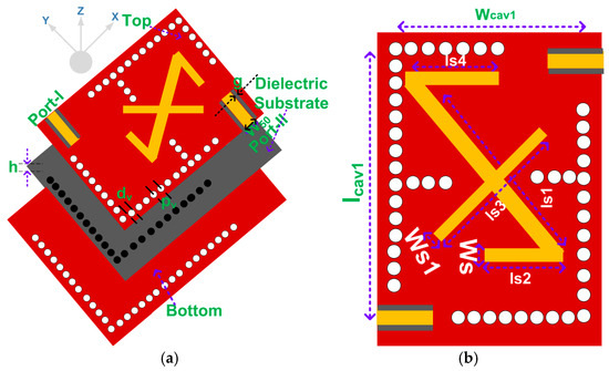
Figure 1.
Proposed inverted Z-shaped radiating slot-based antenna design: (a) three-dimensional view and (b) top view.

Table 1.
Proposed antenna geometric parameters.
The resonance frequencies for the fundamental and higher-order modes () of the proposed modified FMSIW rectangular cavity-backed antenna were calculated using the following formula [16,17]:
where m and n are integers (1, 2, 3 …), representing half-cycle field variations in the x- and y-directions; and and represent the permittivity and permeability of the dielectric substrate, respectively.
The equivalent length () and width () are determined using the following equations:
where as and are the length and width of the proposed modified rectangular FMSIW antenna; and and represent the via diameter and the spacing between contiguous vias.
To minimize energy leakage, the following conditions should be maintained: a diameter-to-wavelength ratio () of ≤0.1, a diameter-to-pitch ratio ( 0.66) of ≥0.5, and a wavelength of concerning the lowest resonance frequency of the dielectric material. Due to the significantly higher aspect ratio of the proposed FMSIW in terms of width to height, only specific modes resonate within the FMSIW resonator. The primary measurements are determined to ensure that the mode works within the targeted frequency range, as depicted in Figure 2a.
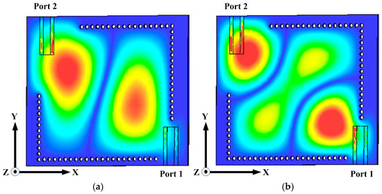
Figure 2.
Distribution of electrical fields in the original rectangular SIW cavity under Eigenmode simulation: (a) TE210 mode at 10.3 GHz with Port 1 excitation; (b) TE220 mode at 14.06 GHz with Port 2 excitation.
2.2. Eigenmode Analysis with and Without a Slot
To determine the mode configuration of the proposed SDA, the Eigenmode solver in CST MS 2024 software was used, as shown in Figure 2 and Figure 3. Firstly, an FMSIW with a rectangular cavity without a radiating slot was used in the Eigenmode analysis to determine the distribution of the electric field (Figure 2). Figure 2 shows that the working modes of the cavity without a radiating slot are and at 10.30 GHz and 14.06 GHz, respectively, as shown in Figure 2a and Figure 2b. Next, four slots, which are a combination of vertical, horizontal, and diagonal slots, are incorporated.
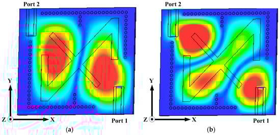
Figure 3.
Distribution of electric fields in the modified inverted Z-shaped rectangular SIW cavity under Eigenmode simulation: (a) TE210 mode at 11.63 GHz with Port 1 excitation; (b) TE220 mode at 13.27 GHz with Port 2 excitation.
To attain optimal field disruption, the lengths of all four slots vary from to , roughly one-fourth to half of a wavelength, as shown in Figure 3. The modification of the cavity introduces more inductive and capacitive effects, and as a result, the relevant resonant frequencies and modes are altered. Due to this, the resonance frequencies of the and modes move to higher 11.63 GHz and lower 13.27 GHz bands, as displayed in Figure 3a and Figure 3b, respectively. It can be seen from Figure 3 that the highest electric fields occur at specific points due to the symmetrical plane. Because of the high width-to-height ratio of the SIW and the symmetrical plane of the proposed antenna, the normal magnetic field becomes zero. Therefore, the planes mentioned in the FMSIW can be considered equivalent quasi-magnetic walls. Due to the influence of the slot, strong reactive loading is generated, which subsequently affects the mode.
2.3. Equivalent Circuit Model of SDA
An equivalent circuit model was developed in which slots were introduced to create additional capacitance, as depicted in Figure 4a, and the results are shown in Figure 4b. A parallel RLC tank was utilized to symbolize all of the resonators, and an inverted Z-shaped slot was modeled as a shunt capacitor. The first and second resonators of resistance, inductance, and capacitance are represented by R1p, L1p, and C1p and R2p, L2p, and C2p, respectively [18]. These passive elements are connected in a shunt fashion to enable the analysis of the radiated patch values. In contrast, an inverted Z-shaped slot offers shunt capacitances C1seq and C2seq for each port of the circuit diagram. N1 and N2 function as impedance transformers that match the impedance between ports, i.e., microstrip lines and substrate-integrated waveguide cavities. M12 represents the mutual coupling of the two generated resonators, modeled as a series connection of an inductor (Lmn) and capacitor (Cmn). The electrical parameters of the proposed full-mode SIW antenna were found to be R1p = 456 Ω, L1p = 15 nH, C1p = 0.07 pF, R2p = 563 Ω, L2p = 1 nH, C2p = 0.14 pF, and C1seq = 0.05 pF; and C2seq = 0.05 pF, Lmn = 10.5 nH, Cmn = 5.45 Pf, N1 = 0.35, and N2 = 0.39. Using these parameter values, an equivalent circuit model was developed and Keysight ADS was used to determine the circuit results for the S-parameters, as shown in Figure 4b.
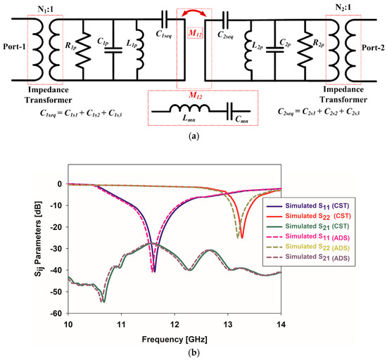
Figure 4.
Equivalent lumped circuit element model of the self-diplexing antenna: (a) circuit element model; (b) S-parameter comparison.
The input impedance and resonance frequency of the resonators associated with port 1 and port 2 are defined as follows:
It has been noted that the resonance frequency is influenced by the inductance of the cavity (Lp) and the slot (Cs) capacitance, as observed in Equation (4). Consequently, the capacitance (Cs) is directly related to the slot dimensions. If the slot dimensions are increased, the capacitance (Cs) rises, causing the resonant frequency to shift toward lower values. The input impedance of the proposed self-diplexing SIW rectangular cavity-backed antenna can be obtained using Equation (5).
3. Proposed Design Methodology and Operational Mechanism
In this section, the different evaluation steps of the proposed self-diplexing antenna design process are discussed and are displayed in Figure 5. In this antenna structure, the first step is to select the shape of the resonator. Here, a rectangular shape has been chosen, which surrounds L-shaped vias to make the SIW cavity structure. In the second stage, a diagonal slot is loaded with the rectangular FMSIW cavity to incorporate the capacitance.
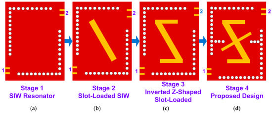
Figure 5.
Different evaluation steps of the proposed antenna: (a) stage 1: SIW resonator; (b) stage 2: slot-loaded SIW; (c) stage 3: inverted Z-shaped slot-loaded SIW; (d) stage 4: proposed design.
The third stage involves the extension of the diagonal slot by including a horizontal slot at the end and an inverted Z-shaped slot, which is used to block EM waves. The final stage involves the incorporation of reactive values in the proposed structure; hence, another diagonal slot is combined with these slots, called a modified inverted Z-shaped slot.
Stage 1:First, the geometry of the antenna was designed, beginning with the selection of rectangular SIW cavities made of L-shaped vias and two microstrip transmission lines. These were then used to feed the RF power, as shown in Figure 5a. The initial dimensions of the proposed antenna were chosen as per Equations (1)–(3), with a length and width of 24 mm and 19 mm, respectively. As also shown in Figure 5a, the feed gaps related to the placement of the L-shaped vias and slots regulate the external Q-factors and, consequently, the input matching at the two ports [19].
Here, the preliminary length and width of the rectangular FMSIW cavity antenna were approximated using Equations (1)–(3), and frequencies of 10.40 GHz and 14.06 GHz were calculated, respectively. Then, a simulation was performed that showed the reflection coefficient (S11) and transmission coefficient (S21) of the proposed cavity; the results are shown in Figure 6a. It can be seen from Figure 5a—Stage 1 and the results in Figure 6a that there is a gap, and the imbalance between the feeder lines and L-shaped vias shown in Figure 2a creates multiple harmonics and good impedance bandwidths in the working bands. Because of the unbalanced feeding network of the proposed antenna, modes are split into even and odd forms [19,20]. If port one (P-1) has been excited, the two modes, and , are split into a pair of even- and odd-form frequencies. The results show that the and modes are excited at resonance frequencies of 10.40 GHz and 11.25 GHz, whereas the and modes are excited at resonance frequencies of 12.37 GHz and 13.94 GHz, respectively. Similarly, if port two (P-2) has been excited, similar kinds of modes are observable— and —which are also split into a pair of even- and odd-form frequencies. Moreover, the and modes are excited at resonance frequencies of 11.23 GHz and 11.78 GHz, whereas the and modes are excited at resonance frequencies of 13.01 GHz and 14.20 GHz, respectively. Concerning port two, the modes of excitation occur at a higher frequency due to the asymmetrical feeding network.
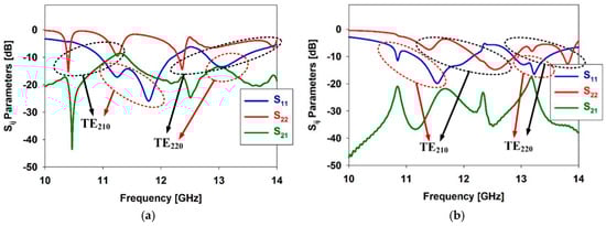
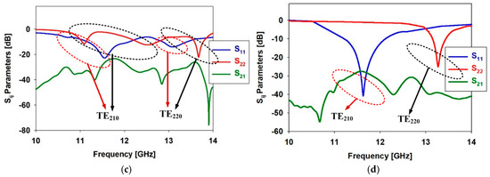
Figure 6.
Sij parameters of the four design steps for the proposed self-diplexing antenna: (a) stage 1; (b) stage 2; (c) stage 3; (d) stage 4/final proposed SDA.
To improve the port isolation of the proposed antenna, especially for the dual-port configuration, it is crucial to minimize interference between ports otherwise the port isolations are unsatisfactory. Here, the port isolation is nearly 10 dB, which is insufficient and occurs due to the absence of isolation structures.
Stage 2:This stage of the antenna design and the results of the testing are illustrated in Figure 5b and Figure 6b, respectively, where a diagonal slot is used to improve the isolation and control the capacitance values. In the stage 1 structure, there are no radiated slots. Nevertheless, it shows good radiation because inductors and capacitors both in series and in parallel are found in the cavity-backed rectangular SIW, as shown in the equivalent lumped circuit element model depicted in Figure 4 [21]. Stage 2 mainly focuses on merging the resonances or obtaining wideband, and improving the isolation between the two ports. To achieve this, a diagonal rectangular-shaped slot is incorporated, separating both ports. The results are presented in Figure 6b. Due to this, there is an interruption in the surface current distribution on the FMSIW cavity, therefore reducing the coupling between the ports and improving isolation by mitigating unwanted signals. At this point, adding the slot may increase or decrease the capacitance of the proposed structure, but this fully depends on the width of the slot. Here, the width of the slot is effectively optimized so that it can decrease the capacitance and shift the frequency upward.
Stage 3:This design stage involves the insertion of two horizontal slots on either side of the diagonal slot using the mode-merging technique. The addition of these slots also controls the isolation. The design structure and S-parameter results are depicted in Figure 5c and Figure 6c, respectively. The even and odd modes in the proposed antenna are merged due to the presence of multiple slots, i.e., the incorporation of two more horizontal slots along with a diagonal slot. The placement of these slots creates an asymmetrical design known as an inverted Z-shaped slot, causing both even and odd modes to exist at closely spaced frequencies. The proposed methodology allows mode merging without requiring complex additional circuitry [22,23]. Additionally, to reduce the transmission coefficients, these extra slots disrupt more surface currents on the proposed antenna geometry, hence reducing the coupling of the two ports and showing good isolation, as shown in Figure 6c. The addition of horizontal slots perturbs the surface current distribution on the radiating slot, introducing additional current paths and modifying the effective electrical length of the antenna. These slots create perturbations that support both even and odd current modes; importantly, they also introduce coupling between these modes. As a result, the resonance frequencies associated with the even and odd modes shift, forming a more unified and broadened resonance. This leads to an improvement in impedance-matching and bandwidth characteristics, as observed in the simulated S11 and gain responses. Furthermore, the horizontal slots increase capacitive loading, which helps tune the resonance and flatten the response near the design frequency.
Stage 4:The final design stage of the proposed antenna utilizes the mode-merging technique to remove unwanted harmonics. This is achieved by the insertion of another diagonal slot—creating the inverted Z-shaped slot—which can cause both even and odd modes to exist at closely spaced frequencies. The final proposed SIW-based self-diplexing antenna configuration and its results are shown in Figure 5d and Figure 6d, respectively. It can be seen that the use of multiple slots is useful for disturbing/separating the surface currents, leading to combined even and odd modes for enhancing certain radiation properties—in this case, the bandwidth, which can be observed in Figure 6d. Hence, the proposed self-diplexing antenna shows a −10 dB impedance bandwidth for the lower and upper bands of 7.4% (11.23–12.09 GHz) and 3.0% (13.15–13.55 GHz), respectively.
In terms of improving the isolation between the two ports, these multiple slots are useful for creating a virtual boundary or preventing surface current transfer from one part of the patch to another, as shown in Figure 7. They reduce the coupling between these ports and offer very good isolation of approximately 28 dB.
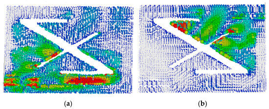
Figure 7.
Electric field distribution of the proposed SDA: (a) port one at 11.63 GHz; (b) port two at 13.27 GHz.
4. Examination of Essential Properties
This section focuses on validating the key performance aspects of the proposed SIW self-diplexing antenna. Emphasis is placed on examining its filtering characteristics and diplexing behavior.
4.1. Validation of Filtering Characteristics
The working mechanism of the filtering response was examined using coupling topology, as displayed in Figure 8a, and the result is shown in Figure 8b. When multiple slots are incorporated within the rectangular SIW cavity, two coupling routes are created: the primary coupling route, S-SC-PT-LD, and the cross-coupling route, S-SC-LD. Because of the gap surrounding the patch created by the slots, electromagnetic energy can couple into free space, thereby establishing a cross-coupling route. These two routes exhibit equal amplitude but opposite phases; hence, a radiation null forms at the upper side of the working band. The radiation null in the lower working band is achieved by the resonance of the mode, which is generated by the proposed cavity. Because the slots are etched at the center of the cavity, the mode resonates, dividing the currents into both sides of the slots that are equal in magnitude but opposite in direction, resulting in no cross-current within the slot [24,25,26].
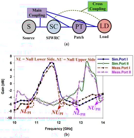
Figure 8.
(a) Coupling topology; (b) filtering validations.
4.2. Validation of Self-Diplexing Concept
Figure 9 presents the E-field orientation of the proposed rectangular FMSIW cavity when both ports are excited. It is clear that the field produced by one port is primarily contained within its patch, showing minimal interaction with other ports; this verifies the self-diplexing characteristics of the design [27,28]. The single structure of the antenna allows it to independently handle EM waves at two distinct frequency bands, and these frequencies are naturally separated due to the antenna’s inherent single configuration. Under controlled excitation, the proposed self-diplexing antenna with a modified inverted Z-shaped cavity naturally divides these two frequencies, as shown in Figure 9a,b. If P-1 is excited and P-2 is open-ended, radiation travels through the slots and open areas and then transfers electromagnetic waves from one side to another, acting as a Tx and Rx section and radiating at a lower resonance frequency of 11.63 GHz. Similarly, when P-2 is excited and P-1 is open-ended, radiation travels through the slots and open areas and then transfers electromagnetic waves from one side to the other, acting as an Rx and Tx section and radiating at a lower resonance frequency of 13.27 GHz.
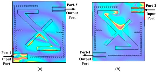
Figure 9.
E-field distribution. (a) Port one, 11.63 GHz; (b) port two, 13.27 GHz.
5. Experimental Results and Verification
To confirm the simulated results, a prototype self-diplexing antenna was fabricated (Figure 10a,b) and near- and far-field measurements were conducted using a vector network analyzer and an anechoic chamber, with the setup shown in Figure 10c and Figure 10d, respectively. Figure 11 displays the measured and simulated S-parameter (|Sij|) results, where measured reflection coefficients (S11 and S22 −10 dB) for lower frequency (fL) and upper frequency (fU) bands show fractional bandwidths of 7.4% (11.23–12.09 GHz) and 3.0% (13.15–13.55 GHz), respectively. Furthermore, the measured isolation (|S21|) of the lower- and upper-frequency bands reached more than 28 dB, as shown in Figure 11. Figure 12a presents the gain analysis of the proposed antenna design, considering both the simulation and measurement results across the working bands, and shows the measured values for the lower and higher frequency bands of 6.14 dBi and 6.16 dBi, respectively. The overall efficiency spanning the working bands, as shown in Figure 12b, achieved measured values of more than 87.32%, whereas the simulated values were approximately 90.13% within the −10 dB bandwidth. Figure 13 displays the measured and simulated normalized co-polarized radiation pattern plots on the E-plane and H-plane for two distinct frequency bands. The co-polarizations remain less than 15.0 decibels together the XZ and YZ planes, according to the measurement data for both resonance frequencies at, for example, 11.63 GHz and 13.27 GHz, respectively. The fabricated antenna prototype was tested using a vector network analyzer to measure the S-parameters. The measurements were conducted in an anechoic chamber to ensure minimal external interference. Antenna parameters such as return loss (S11, S22), isolation (S21), and radiation patterns were obtained and compared with the simulated results. The radiation patterns were measured on both E- and H-planes at the respective resonant frequencies corresponding to the TE210 and TE220 modes.
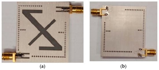
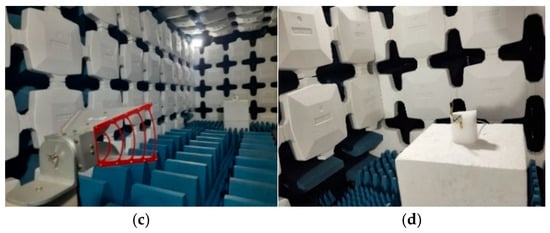
Figure 10.
Proposed fabricated antenna. (a) Top view; (b) bottom view; (c) radiation pattern; (d) gain measurement in an anechoic chamber.
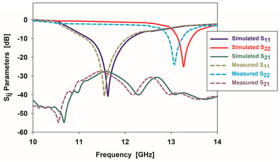
Figure 11.
Proposed simulated and measurement results of Sij parameters.
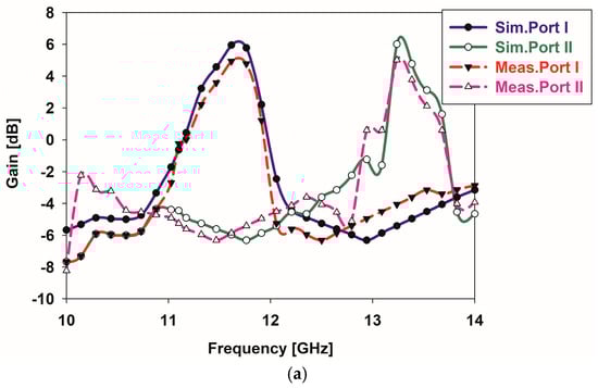
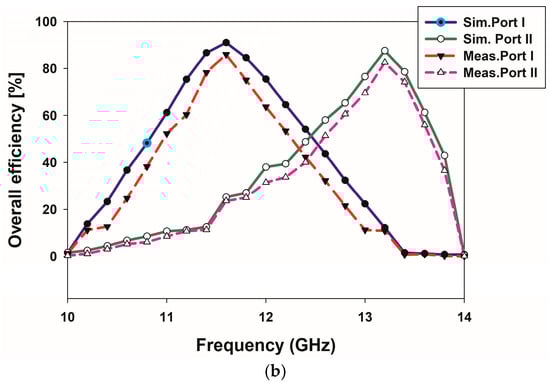
Figure 12.
Simulation and measurement result of gain and overall efficiency of the proposed SDA: (a) gain; (b) overall efficiency.
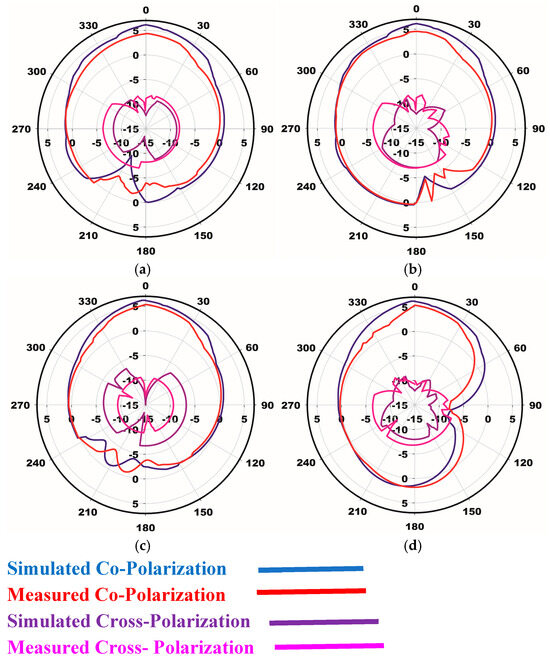
Figure 13.
Measurements and simulations of the radiation patterns: (a) E-plane at 11.63 GHz; (b) H-plane at 11.63 GHz; (c) E-plane at 13.27 GHz; (d) H-plane at 13.27 GHz.
Table 2 illustrates the proportional analysis of the proposed filtenna design compared with existing state-of-the-art antenna/filtenna designs. Here, the performance of the antenna/filtenna is analyzed in terms of frequency, isolation, gain, and efficiency metrics. The analysis shows that the proposed design has a more compact geometry than the others, achieving a higher efficiency of 90.13% and exhibiting filtenna characteristics.
Table 2.
Comparative analysis between the proposed filtenna/antenna and existing state-of-the-art designs.
To sum up, the design phases for the proposed self-diplexing inverted Z-shaped antenna are as follows:
- As per the authors’ knowledge, this is the first instance of an FMSIW-based self-diplexing antenna featuring an inverted Z-shaped radiating slot.
- Self-diplexing and filtenna characteristics have been achieved by inserting multiple slots at specific locations in the rectangular cavity.
- Two operating frequencies, fL at approximately 11.63 GHz and fH at approximately 13.27 GHz, were obtained by optimizing all of the parameters.
- The equivalent lumped circuit model for the antenna has a rectangular FMSIW cavity.
6. Conclusions
In this study, a novel modified inverted Z-shaped slot radiator-based self-diplexing SIW rectangular cavity was designed and developed for filtering applications. The antenna characteristics were obtained through the insertion of multiple radiating slots at the center and in other locations in the cavity-created coupling routes, cross-coupling routes, and cavity resonance modes. The proposed antenna is supported by two modes, i.e., and , and it was found that two discrete resonance frequencies, 11.63 GHz and 13.27 GHz, are useful for obtaining self-diplexing properties. The antenna structure was optimized based on the given equations to achieve better performance. The antenna exhibits decent gain (>6 dBi), better isolation (>28 dB), and an overall efficiency of 90.13% for both X and Ku band applications. The proposed design can be extended by integrating reconfigurable elements to enable dynamic frequency tuning or switching between multiple bands. In addition, the proposed antenna exhibits better performance than existing models.
Author Contributions
Conceptualization, R.A. and R.K.; methodology, R.K.; software, R.A.; validation, R.A.; formal analysis, R.A.; investigation, R.K.; resources, R.A.; data curation, R.A.; writing—original draft preparation, R.A.; writing—review and editing, R.K.; visualization, R.K.; supervision, R.K. All authors have read and agreed to the published version of the manuscript.
Funding
This research received no external funding.
Data Availability Statement
Data were obtained from the experimental and simulation software designed in this study using rigorous calculations and logical reasoning.
Acknowledgments
The authors thank the Vellore Institute of Technology (VIT), Vellore, Tamil Nadu, India, for providing ‘VIT SEED GRANT (RGEMS)-Sanctioned Order No. SG20230130’ for providing the materials used for the experiments in this research.
Conflicts of Interest
The authors declare no conflicts of interest.
References
- Xiang, B.J.; Zheng, S.Y.; Wong, H.; Pan, Y.M.; Wang, K.X.; Xia, M.H. Flexible Dual-Band Antenna With Large Frequency Ratio and Different Radiation Properties Over the Two Bands. IEEE Trans. Antennas Propag. 2018, 66, 657–667. [Google Scholar] [CrossRef]
- Iqbal, A.; Hasan, M.A.; Mabrouk, I.B.; Nedil, M. Ultracompact Quarter-Mode Substrate Integrated Waveguide Self-Diplexing Antenna. IEEE Antennas Wirel. Propag. Lett. 2021, 20, 1269–1273. [Google Scholar] [CrossRef]
- Ravindiran, A.; Rajkishor, K. Design and Implementation of Novel H -Shaped Self-Diplexing SIW Rectangular Cavity-Backed Antenna with Harmonic Suppression for Terrestrial Communications. Int. J. Antennas Propag. 2024, 6618202, 1–10. [Google Scholar]
- Mao, C.X.; Jiang, Z.H.; Werner, D.H.; Gao, S.S.; Hong, W. Compact Self-Diplexing Dual-Band Dual-Sense Circularly Polarized Array Antenna With Closely Spaced Operating Frequencies. IEEE Trans. Antennas Propag. 2019, 67, 4617–4625. [Google Scholar] [CrossRef]
- Yang, X.; Lin, X.Q.; Wang, B.; Su, Y. A Dual-Wideband Structure-Shared Antenna With Self-Diplexing Property for High-Power Microwave Application. IEEE Trans. Antennas Propag. 2021, 69, 4201–4205. [Google Scholar] [CrossRef]
- Divya, C.; Arvind, K. A QMSIW Cavity-backed Self-Diplexing Antenna with Tunable Resonant Frequency using CSRR Slot. IEEE Antennas Wirel. Propag. Lett. 2024, 23, 259–263. [Google Scholar]
- Barik, R.K.; Koziel, S. Microfluidically frequency-reconfigurable compact self-quadruplexing tunable antenna with high isolation based on substrate integrated waveguide. Sci. Rep. 2024, 14, 920. [Google Scholar] [CrossRef]
- Kumar, A.; Kumar, M.; Singh, A.K. On the Behavior of Self-Triplexing SIW Cavity Backed Antenna With Non-Linear Replicated Hybrid Slot for C and X-Band Applications. IEEE Access 2022, 10, 22952–22959. [Google Scholar] [CrossRef]
- Arvind, K.; Rosaline, S.I. Hybrid half-mode SIW cavity-backed diplex antenna for on-body transceiver applications. Appl. Phys. A Mater. Sci. Process 2021, 127, 834. [Google Scholar]
- Boukarkar, A.; Lin, X.Q.; Jiang, Y.; Yu, Y.Q. A tunable dual-fed self-diplexing patch antenna. IEEE Trans. Antennas Propag. 2017, 65, 2874–2879. [Google Scholar] [CrossRef]
- Barik, R.K.; Koziel, S.; Cheng, Q.S.; Szczepanski, S. Highly Miniaturized Self-Diplexed U-Shaped Slot Antenna Based on Shielded QMSIW. IEEE Access 2021, 9, 158926–158935. [Google Scholar] [CrossRef]
- Hu, K.Z.; Tang, M.C.; Wang, Y.; Li, D.; Li, M. Compact Vertically Integrated Duplex Filtenna With Common Feeding and Radiating SIW Cavities. IEEE Trans. Antennas Propag. 2021, 69, 502–507. [Google Scholar] [CrossRef]
- Kumar, K.; Priya, S.; Dwari, S.; Mandal, M.K. Self-quadruplexing circularly polarized SIW cavity-backed slot antennas. IEEE Trans. Antennas Propag. 2020, 68, 6419–6423. [Google Scholar] [CrossRef]
- Lee, Y.J.; Tarng, J.H.; Chung, S.J. A Filtering Diplexing Antenna for Dual-Band Operation With Similar Radiation Patterns and Low Cross-Polarization Levels. IEEE Antennas Wirel. Propag. Lett. 2017, 16, 58–61. [Google Scholar] [CrossRef]
- Iqbal, A.; Selmi, M.A.; Abdulrazak, L.F.; Saraereh, O.A.; Mallat, N.K.; Smida, A. A Compact Substrate Integrated Waveguide Cavity-Backed Self-Triplexing Antenna. IEEE Trans. Circuits Syst. II Express Briefs 2020, 67, 2362–2366. [Google Scholar] [CrossRef]
- Bozzi, M.; Georgiadis, A.; Wu, K. Review of substrate-integrated waveguide circuits and antennas. Microw. Antennas Propag. 2011, 5, 909–920. [Google Scholar] [CrossRef]
- Xu, F.; Wu, K. Guided-wave and leakage characteristics of substrate integrated waveguide. IEEE Trans. Microw. Theory Tech. 2005, 53, 66–73. [Google Scholar] [CrossRef]
- Pradhan, N.C.; Subramanian, K.S.; Barik, R.K.; Cheng, Q.S. A shielded-QMSIW-based self-diplexing antenna for closely spaced bands and high isolation. IEEE Antennas Wirel. Propag. Lett. 2021, 20, 2382–2386. [Google Scholar] [CrossRef]
- Khan, A.A.; Mandal, M.K. Compact self-diplexing antenna using dual-mode SIW square cavity. IEEE Antennas Wirel. Propag. Lett. 2019, 18, 343–347. [Google Scholar] [CrossRef]
- Jin, C.; Li, R.; Alphones, A.; Bao, X. Quarter-Mode Substrate Integrated Waveguide and Its Application to Antennas Design. IEEE Trans. Antennas Propag. 2013, 61, 2921–2928. [Google Scholar] [CrossRef]
- Bozzi, M.; Perregrini, L.; Wu, K. Modeling of conductor, dielectric and radiation losses in substrate integrated waveguide by the boundary integral-resonant mode expansion method. IEEE Trans. Microw. Theory Tech. 2008, 56, 3153–3161. [Google Scholar] [CrossRef]
- Yang, D.; Chen, Z.N.; Yin, J.; Liu, P. Mode Conversion for Broadband Mutual Coupling Suppression of a Slot-Fed Metasurface Mosaic Antenna. IEEE Trans. Antennas Propag. 2024, 72, 6930–6938. [Google Scholar] [CrossRef]
- Sun, L.; Li, Y.; Zhang, Z.; Feng, Z. Low-Profile Compact Circularly Polarized Slot-Etched PIFA Using Even and Odd Modes. IEEE Trans. Antennas Propag. 2019, 67, 4189–4194. [Google Scholar] [CrossRef]
- Arvind, K.; Althuwayb, A.A. SIW Resonator-Based Duplex Filtenna. IEEE Antennas Wirel. Propag. Lett. 2021, 20, 2544–2548. [Google Scholar] [CrossRef]
- Xu, H.; Liu, H.; Huang, T.; Liu, T.Y. 3-D-Printed Dual-Band Circularly Polarized Filtering Antenna With Self-Diplexing Property for Millimeter-Wave Applications. IEEE Trans. Antennas Propag. 2024, 72, 3807–3812. [Google Scholar] [CrossRef]
- Wang, Y.; Xu, J.; Xiang, L.; Chen, K.; Hong, W. Low-Cost Wideband Millimeter-Wave Filtenna and Its Arrays for Miniaturized IoT Devices. IEEE Trans. Antennas Propag. 2022, 70, 2283–2288. [Google Scholar] [CrossRef]
- Lu, Y.C.; Lin, Y.C. A Mode-Based Design Method for Dual-Band and Self-Diplexing Antennas Using Double T-Stubs Loaded Aperture. IEEE Trans. Antennas Propag. 2012, 60, 5596–5603. [Google Scholar] [CrossRef]
- Dash, S.K.K.; Cheng, Q.S.; Barik, R.K.; Jiang, F.; Pradhan, N.C.; Subramanian, K.S. A Compact SIW Cavity-Backed Self-Multiplexing Antenna for Hexa-Band Operation. IEEE Trans. Antennas Propag. 2022, 70, 2283–2288. [Google Scholar] [CrossRef]
- Agrawal, M.; Kumar, T. A Semicircular Substrate Integrated Waveguide- Based Self-Diplexing Slot Antenna With Polarization Flexibility. IEEE Antennas Wirel. Propag. Lett. 2023, 22, 1518–1521. [Google Scholar] [CrossRef]
- Pourmohammadi, P.; Naseri, H.; Melouki, N.; Ahmed, F.; Iqbal, A.; Vandenbosch, G.A.E.; Denidni, T.A. Substrate Integrated Waveguide-Based Full-Duplex Antenna With Improved Out-of-Band Suppression. IEEE Trans. Circuits and Syst. II Express Briefs 2023, 70, 1430–1434. [Google Scholar] [CrossRef]
- Pradhan, N.C.; Reddy, M.G.; Subramanian, K.S.; Barik, R.K.; Koziel, S.; Cheng, Q.S. Microfluidic SIW-Based Tunable Self-Diplexing Antenna for Sub-6 GHz Band Applications. IEEE Trans. Circuits and Syst. II Express Briefs 2023, 70, 1435–1439. [Google Scholar] [CrossRef]
- Dhwaj, K.; Tian, H.; Itoh, T. Low-profile dual-band filtering antenna using common planar cavity. IEEE Antennas Wirel. Propag. Lett. 2018, 17, 1081–1084. [Google Scholar] [CrossRef]
Disclaimer/Publisher’s Note: The statements, opinions and data contained in all publications are solely those of the individual author(s) and contributor(s) and not of MDPI and/or the editor(s). MDPI and/or the editor(s) disclaim responsibility for any injury to people or property resulting from any ideas, methods, instructions or products referred to in the content. |
© 2025 by the authors. Licensee MDPI, Basel, Switzerland. This article is an open access article distributed under the terms and conditions of the Creative Commons Attribution (CC BY) license (https://creativecommons.org/licenses/by/4.0/).