A DC-Link Current Pulsation Compensator Based on a Triple-Active Bridge Converter Topology
Abstract
1. Introduction
2. Design of a Control Algorithm for AC Component Compensation
2.1. Reduced-Order Model of the TAB Converter
2.2. Decoupling of the Converter Inputs
2.3. Design of the Control Loop
3. Simulation and Experimental Results
3.1. Open-Loop Testing
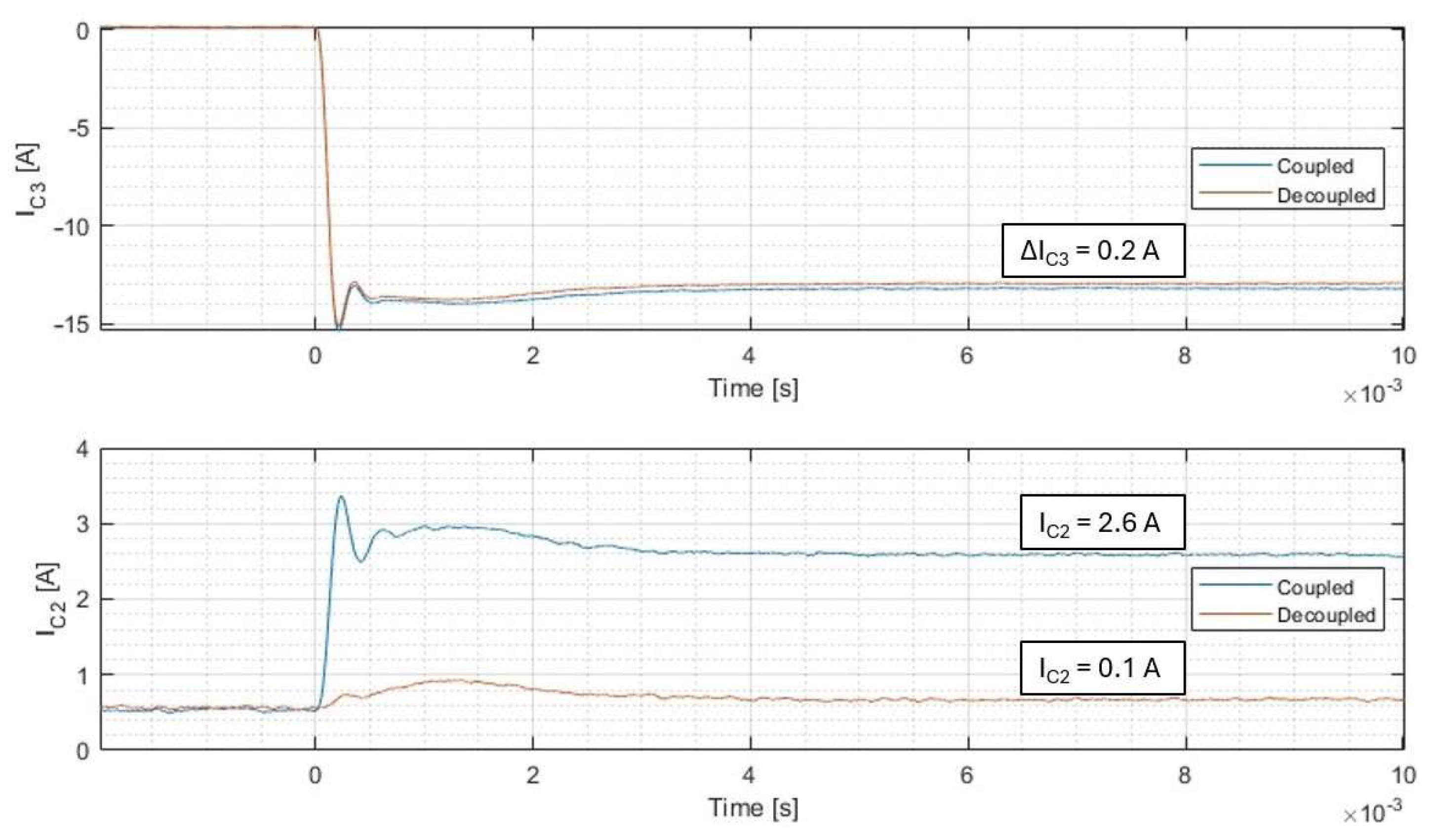
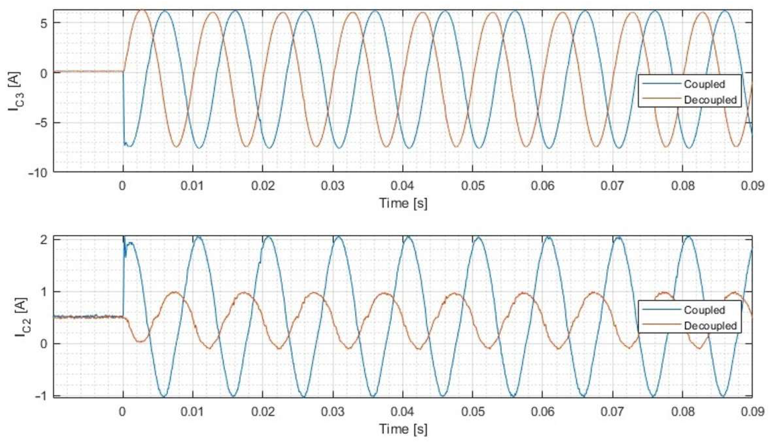
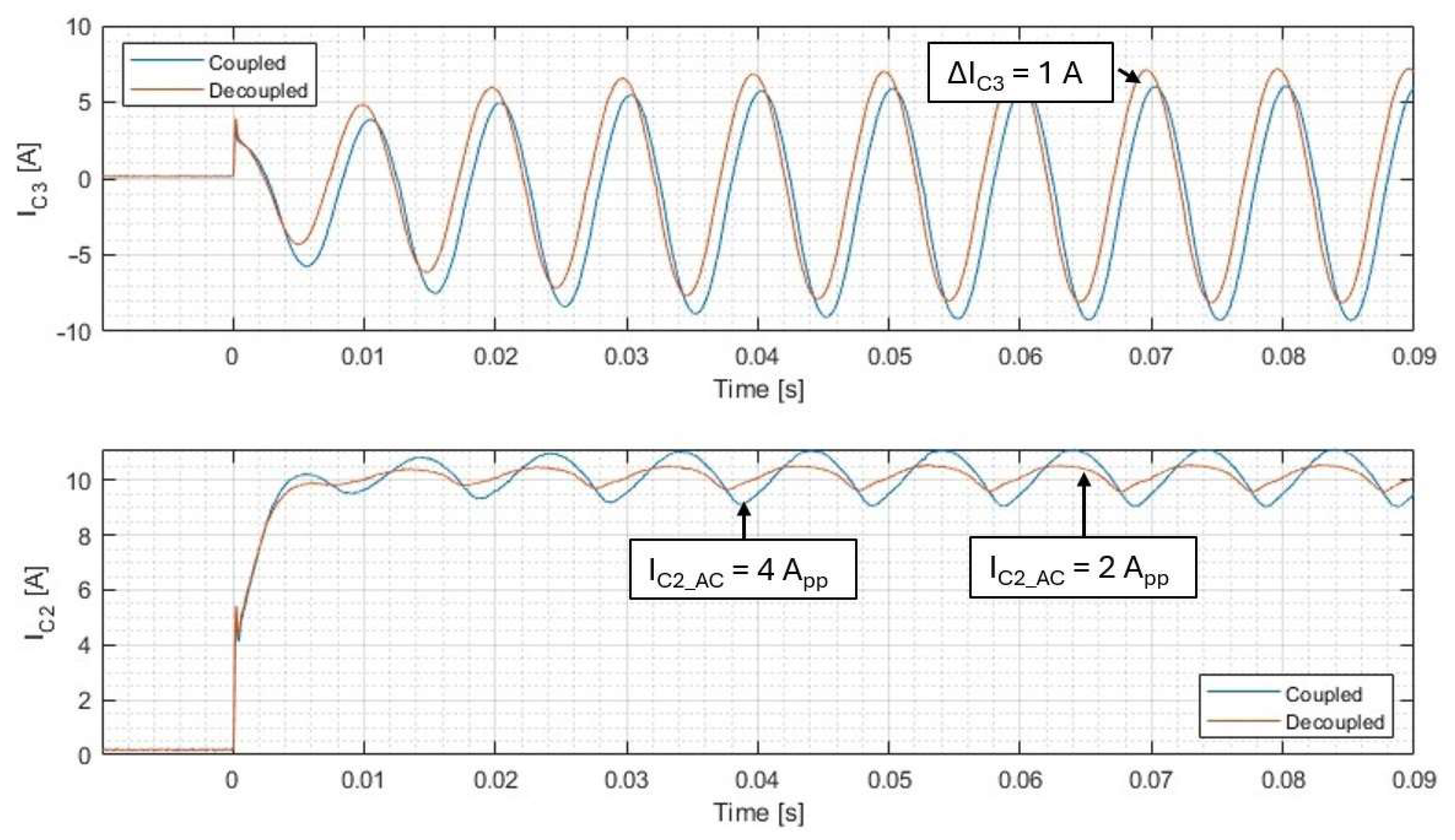
3.2. Simulation of the Control Loop
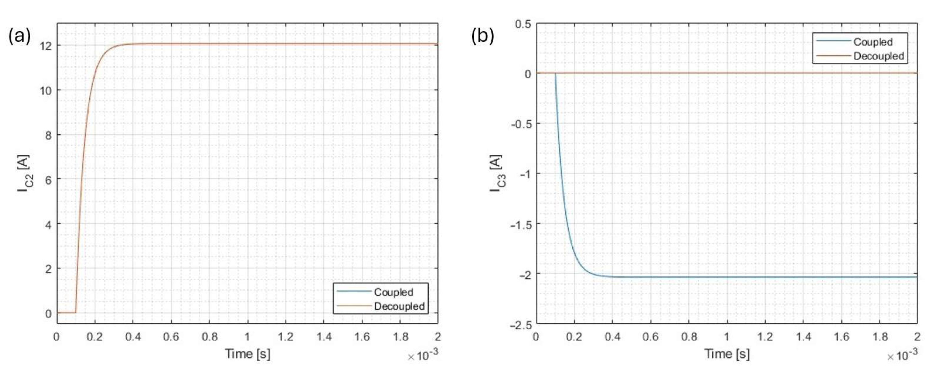
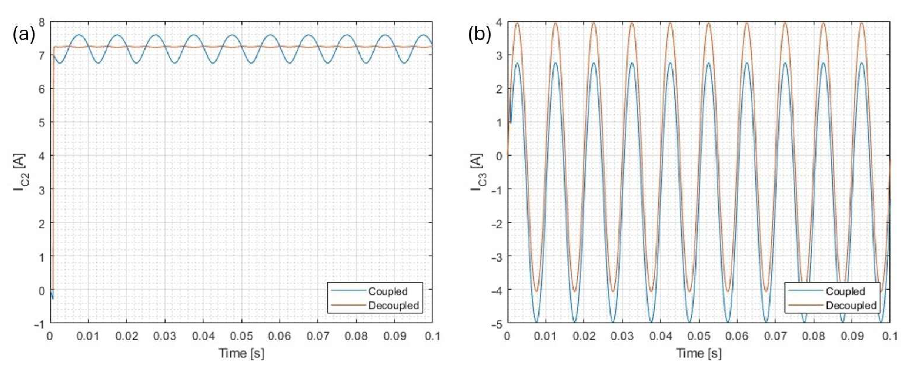
- Operation of the decoupling algorithm
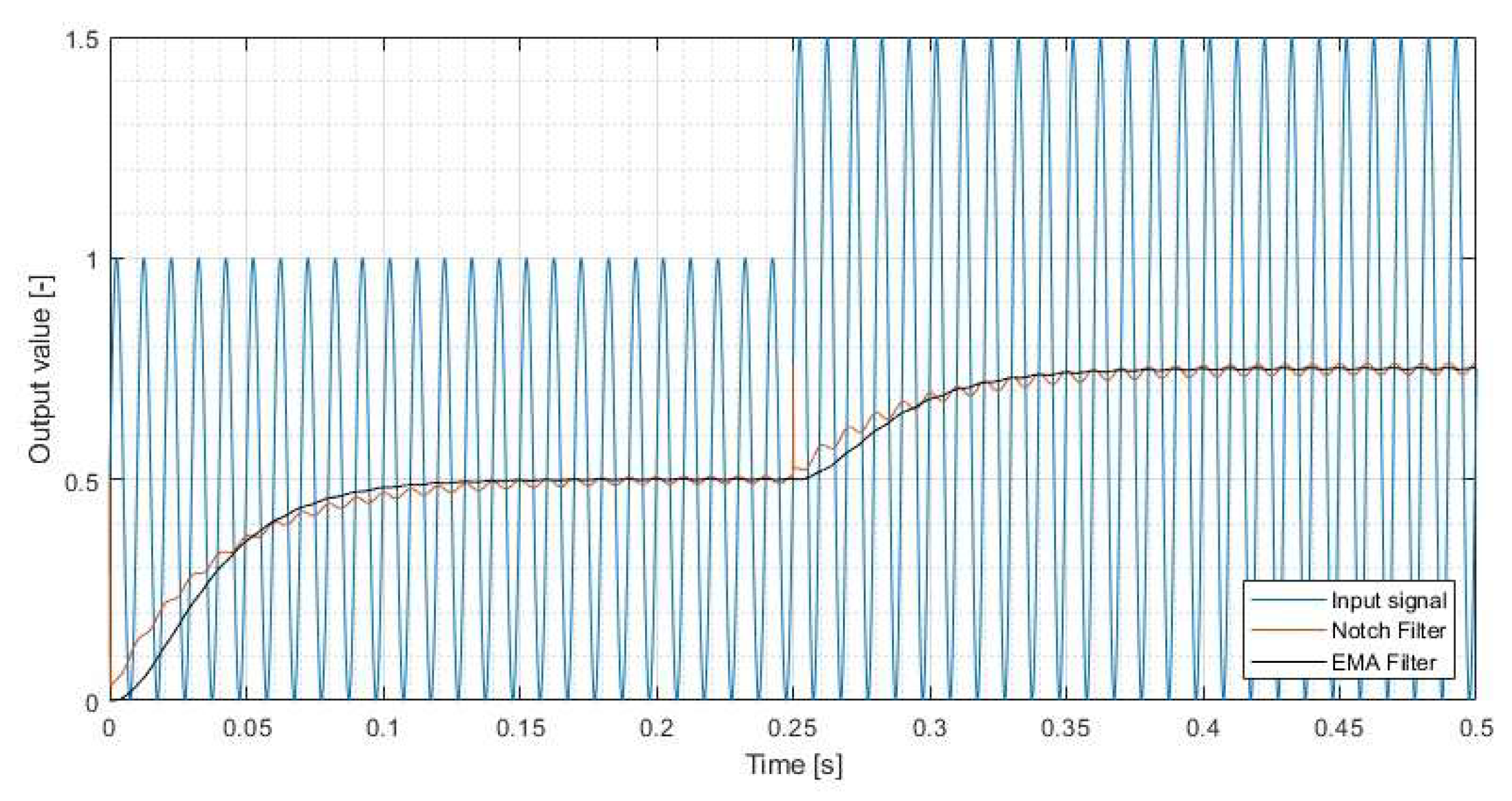
- Operation of the EMA filter
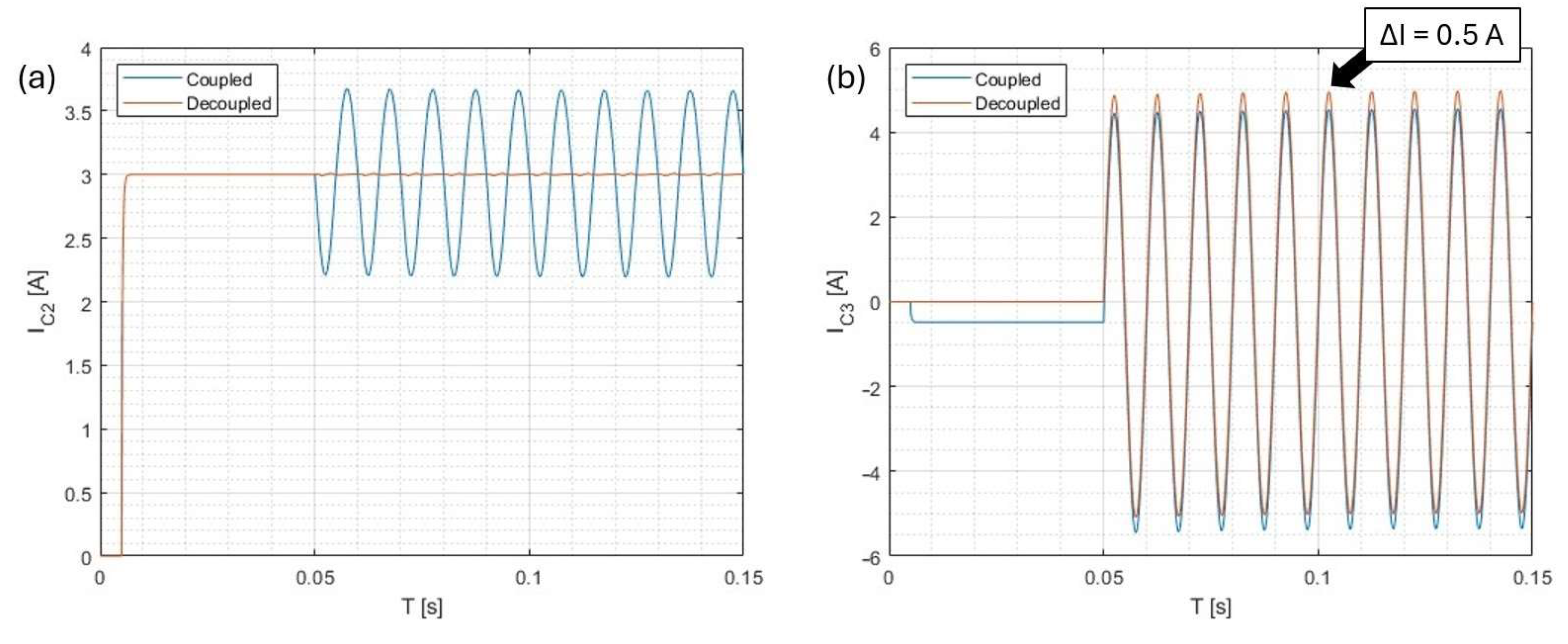
- Operation of the PI/PR controllers
- Operation of the standalone mode
- Since the final control loops are current control loops, the tests evaluate the output current responses to the phase inputs.
3.2.1. Simulation of the Decoupling Algorithm
3.2.2. Simulation of the Exponential Moving Average Filter
3.2.3. Simulation of the PI/PR Controllers
3.2.4. Simulation of the Standalone Mode
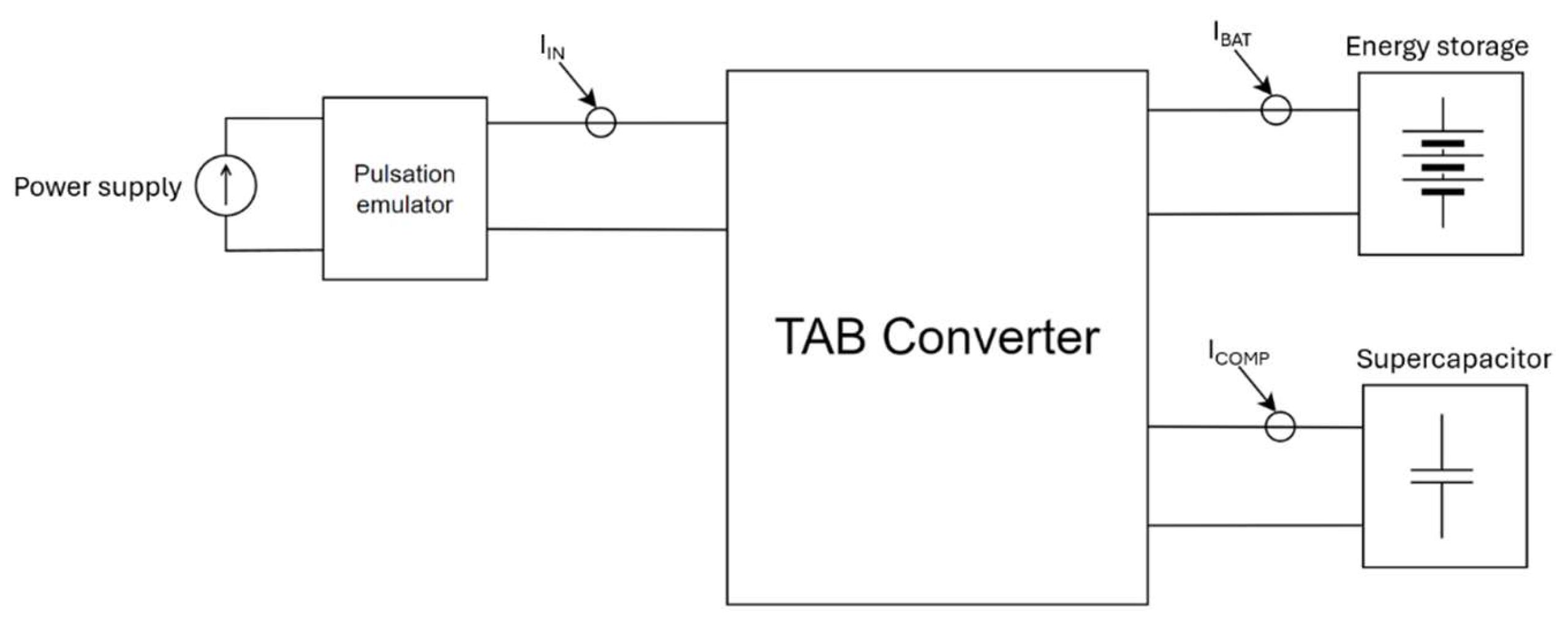
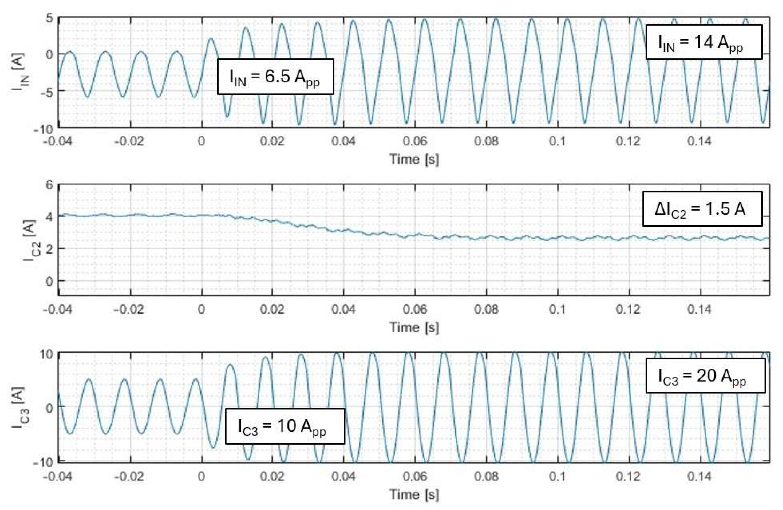
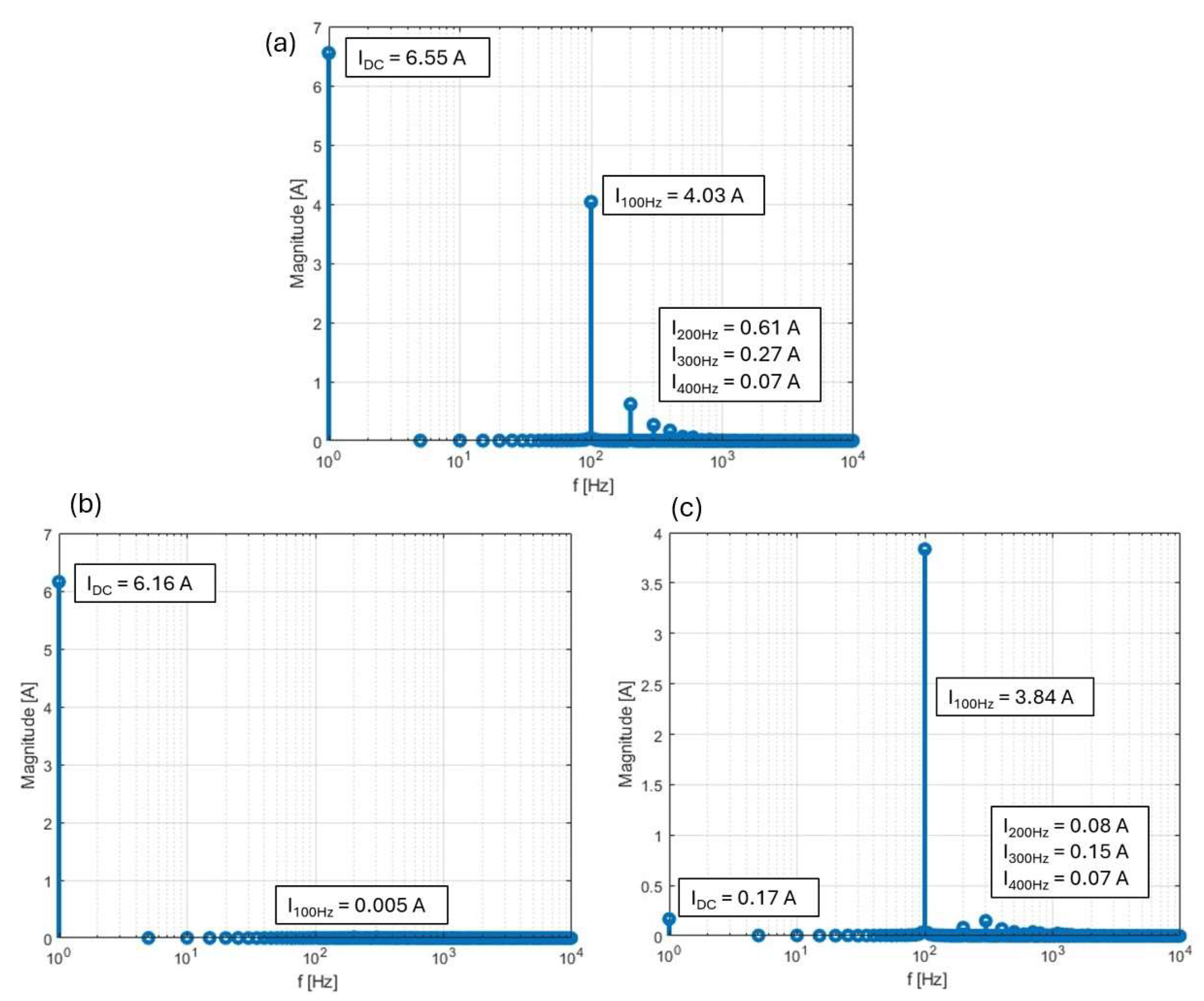
3.3. Experimental Verification of the Closed-Loop Operation
3.4. Standalone Mode Operation
4. Results Discussion
5. Conclusions
Author Contributions
Funding
Data Availability Statement
Conflicts of Interest
Correction Statement
Abbreviations
| EMA | Exponential moving average |
| PI | Proportional integral |
| PR | Proportional resonant |
| TAB | Triple-Active Bridge |
Appendix A


References
- Vechiu, I.; Etxeberria, A.; Tabart, Q.; Lopez, R. Operational Limits of Four Wires Three Levels NPC Topology for Power Quality Improvement in Weak Grids. In Proceedings of the 2016 IEEE 16th International Conference on Environment and Electrical Engineering (EEEIC), Florence, Italy, 7–10 June 2016; pp. 1–5. [Google Scholar]
- Zieliński, D.; Stefańczak, B.; Jędrys, K. Phase-Independent Reactive Power Compensation Based on Four-Wire Power Converter in the Presence of Angular Asymmetry between Voltage Vectors. Energies 2022, 15, 497. [Google Scholar] [CrossRef]
- Ji, Y.; Wang, C.Y. Heating Strategies for Li-Ion Batteries Operated from Subzero Temperatures. Electrochim. Acta 2013, 107, 664–674. [Google Scholar] [CrossRef]
- Kacetl, T.; Kacetl, J.; Tashakor, N.; Goetz, S. A Simplified Model for the Battery Ageing Potential Under Highly Rippled Load. In Proceedings of the 2022 24th European Conference on Power Electronics and Applications (EPE’22 ECCE Europe), Hannover, Germany, 5–9 September 2022; pp. 1–10. [Google Scholar]
- Vermeer, W.; Stecca, M.; Mouli, G.R.C.; Bauer, P. A Critical Review on The Effects of Pulse Charging of Li-Ion Batteries. In Proceedings of the 2021 IEEE 19th International Power Electronics and Motion Control Conference (PEMC), Gliwice, Poland, 25–29 April 2021; pp. 217–224. [Google Scholar]
- Rąbkowski, J.; Król, K.; Zdanowski, M.; Skotnicki, M. GaN-Based Soft-Switched Active Power Buffer Operating at ZCS-Problems of Start-up and Shut-Down. Bull. Pol. Acad. Sci. Tech. Sci. 2020, 68, 785–792. [Google Scholar] [CrossRef]
- Komeda, S.; Ohnuma, Y. An Isolated Single-Phase AC-DC Converter Basedon a Dual Active Bridge Converter and an Active Energy Buffer Circuit. In Proceedings of the 2021 IEEE 30th International Symposium on Industrial Electronics (ISIE), Kyoto, Japan, 20–23 June 2021; pp. 1–6. [Google Scholar]
- Takeuchi, K.; Ohno, T.; Watanabe, H.; Nakata, Y.; Itoh, J.-I. Active Power Decoupling Method Based on Dual Active Bridge Converter without Additional Components. In Proceedings of the 2025 IEEE Applied Power Electronics Conference and Exposition (APEC), Atlanta, GA, USA, 16–20 March 2025; pp. 21–26. [Google Scholar]
- Wang, C.; Nehrir, M.H. Load Transient Mitigation for Stand-Alone Fuel Cell Power Generation Systems. IEEE Trans. Energy Convers. 2008, 22, 864–872. [Google Scholar] [CrossRef]
- Choi, M.-E.; Kim, S.-W.; Seo, S.-W. Energy Management Optimization in a Battery/Supercapacitor Hybrid Energy Storage System. IEEE Trans. Smart Grid 2012, 3, 463–472. [Google Scholar] [CrossRef]
- Fatyga, K.; Zieliński, D. Sensorless Current Pulsation Compensation in a Hybrid Energy Storage. Appl. Sci. 2023, 13, 2252. [Google Scholar] [CrossRef]
- Liu, C.; Li, B.; Zhang, Y.; Jiang, Q.; Liu, T. The LCC Type DC Grids Forming Method and Fault Ride-through Strategy Based on Fault Current Limiters. Int. J. Electr. Power Energy Syst. 2025, 170, 110843. [Google Scholar] [CrossRef]
- Cai, Y.; Li, J.; Gu, C.; Yang, J.; Guenter, S.; Buticchi, G.; Zhang, H. A Modular Modulation Decoupling Algorithm for Multiple Active Bridge Based Multiport EV Charger. IEEE J. Emerg. Sel. Top. Power Electron. 2024, 12, 3637–3649. [Google Scholar] [CrossRef]
- Costa, L.F.; Buticchi, G.; Liserre, M. Optimum Design of a Multiple-Active-Bridge DC–DC Converter for Smart Transformer. IEEE Trans. Power Electron. 2018, 33, 10112–10121. [Google Scholar] [CrossRef]
- Alam, M.D.; Mahinur Rahman, M.; Awal, M.A.; Husain, I.; Lukic, S. Pulsating Power Processing through Multi-Active Bridge for Electric Vehicle Charging Applications. In Proceedings of the 2024 IEEE Energy Conversion Congress and Exposition (ECCE), Phoenix, AZ, USA, 20–24 October 2024; pp. 2035–2041. [Google Scholar]
- Wasim, M.S.; Habib, S.; Amjad, M.; Bhatti, A.R.; Ahmed, E.M.; Qureshi, M.A. Battery-Ultracapacitor Hybrid Energy Storage System to Increase Battery Life Under Pulse Loads. IEEE Access 2022, 10, 62173–62182. [Google Scholar] [CrossRef]
- Lemian, D.; Bode, F. Battery-Supercapacitor Energy Storage Systems for Electrical Vehicles: A Review. Energies 2022, 15, 5683. [Google Scholar] [CrossRef]
- Vechiu, I.; Camblong, H.; Tapia, G.; Dakyo, B.; Curea, O. Control of Four Leg Inverter for Hybrid Power System Applications with Unbalanced Load. Energy Convers. Manag. 2007, 48, 2119–2128. [Google Scholar] [CrossRef]
- Okutani, S.; Huang, P.-Y.; Kado, Y. Generalized Average Model of Triple Active Bridge Converter. In Proceedings of the 2019 IEEE Energy Conversion Congress and Exposition (ECCE), Baltimore, MD, USA, 29 September–3 October 2019; pp. 5554–5560. [Google Scholar]
- Zou, S.; Lu, J.; Khaligh, A. Modelling and Control of a Triple-Active-Bridge Converter. IET Power Electron. 2020, 13, 961–969. [Google Scholar] [CrossRef]







| Parameter | Value |
|---|---|
| EMA Filter | |
| First-stage coefficient KEMA1 | 0.007 [-] |
| Second-stage coefficient KEMA2 | 0.005 [-] |
| Third-stage coefficient KEMA3 | 0.002 [-] |
| PI Controller | |
| Proportional Gain Kp | 1 [-] |
| Integral Gain KI | 100 [-] |
| High/Low Limits | +/−0.25 [-] |
| PR Controller | |
| Coefficient B0 | 0.0550 [-] |
| Coefficient B1 | 0 [-] |
| Coefficient B2 | −0.0550 [-] |
| Coefficient A0 | 1 [-] |
| Coefficient A1 | 1.9959 [-] |
| Coefficient A2 | −0.9969 [-] |
| Proportional gain Kg | 0.01 [-] |
| Controllers execution rate | |
| Controllers frequency fc | 20 kHz |
| Parameter | Unit | Value |
|---|---|---|
| Transformer parameters | ||
| Turn ratio, primary side n1 | - | 1.73 |
| Turn ratio, secondary side n2 | - | 1.0 |
| Turn ratio, tertiary side n3 | - | 1.0 |
| Series transformer resistance RT1, RT2, RT3 | Ω | 0.02 |
| Leakage inductance, primary side LLK1 | µH | 28.23 |
| Leakage inductance, secondary side LLK2 | µH | 16.0 |
| Leakage inductance, tertiary side LLK3 | µH | 17.96 |
| Magnetizing inductance LM | mH | 3.18 |
| Port parameters | ||
| Input voltage, primary side, V1 | V | 92 |
| Input voltage, secondary side, V2 | V | 55 |
| Input voltage, tertiary side, V3 | V | 55 |
| Output series resistance, secondary side RO2 | Ω | 0.1 |
| Output series resistance, tertiary side RO3 | Ω | 0.1 |
| Output capacitance, secondary side CO2 | µF | 460 |
| Output capacitance, tertiary side CO3 | µF | 460 |
| Other parameters | ||
| Switching frequency fs | kHz | 20 |
| Total converter power | kW | 1.7 |
| Parameter | Unit |
|---|---|
| Oscilloscope | Tektronix MSO5034B |
| Input port measurements I1, I2, I3 | Current probe: Tektronix A622 |
| Transformer current measurement | Current probe: MicSig CP2100A |
| Output voltage measurements | Isolated voltage probe: Pico TA057 |
| Parameter | TAB | Dual DAB |
|---|---|---|
| Number of power semiconductors | 12 | 16 |
| Transformers | 1, 3 windings | 2, 2 windings |
| Control | Centralized, single unit | Decentralized, requires synchronization and robust communication |
| Control complexity | Complex, requires decoupling | Moderate |
| Power density | Higher | Lower |
| Efficiency | Lower, up to 96%, due to a more complex structure | Up to 98% |
Disclaimer/Publisher’s Note: The statements, opinions and data contained in all publications are solely those of the individual author(s) and contributor(s) and not of MDPI and/or the editor(s). MDPI and/or the editor(s) disclaim responsibility for any injury to people or property resulting from any ideas, methods, instructions or products referred to in the content. |
© 2025 by the authors. Licensee MDPI, Basel, Switzerland. This article is an open access article distributed under the terms and conditions of the Creative Commons Attribution (CC BY) license (https://creativecommons.org/licenses/by/4.0/).
Share and Cite
Fatyga, K.; Zdanowski, M. A DC-Link Current Pulsation Compensator Based on a Triple-Active Bridge Converter Topology. Electronics 2025, 14, 3196. https://doi.org/10.3390/electronics14163196
Fatyga K, Zdanowski M. A DC-Link Current Pulsation Compensator Based on a Triple-Active Bridge Converter Topology. Electronics. 2025; 14(16):3196. https://doi.org/10.3390/electronics14163196
Chicago/Turabian StyleFatyga, Karol, and Mariusz Zdanowski. 2025. "A DC-Link Current Pulsation Compensator Based on a Triple-Active Bridge Converter Topology" Electronics 14, no. 16: 3196. https://doi.org/10.3390/electronics14163196
APA StyleFatyga, K., & Zdanowski, M. (2025). A DC-Link Current Pulsation Compensator Based on a Triple-Active Bridge Converter Topology. Electronics, 14(16), 3196. https://doi.org/10.3390/electronics14163196


