Article

Construction of a Machining Process Knowledge Graph and Its Application in Process Route Recommendation

1
Shaanxi Key Laboratory of Advanced Manufacturing and Evaluation of Robot Key Components, Baoji 721016, China
2
School of Mechanical Engineering, Baoji University of Arts and Sciences, Baoji 721016, China
*
Author to whom correspondence should be addressed.
Electronics 2025, 14(15), 3156; https://doi.org/10.3390/electronics14153156 (registering DOI)
Submission received: 7 July 2025 / Revised: 2 August 2025 / Accepted: 5 August 2025 / Published: 7 August 2025
(This article belongs to the Special Issue Human Robot Interaction: Techniques, Applications, and Future Trends)

Abstract

This paper proposes a knowledge graph (KG) construction method for a part machining process in response to the low degree of structuring of historical process data association relationships within the enterprise in the field of part machining, which makes it difficult to reuse effectively. The part types are mainly shafts, gears, boxes and other common parts. First, the schema layer of the process knowledge graph was constructed using a top-down approach. Second, deep learning techniques were employed for entity extraction, while knowledge fusion and ontology relationship establishment methods were combined to build the data layer of the process knowledge graph (PKG) from the bottom up. Third, the mapping between the schema layer and data layer was implemented in the Neo4j graph database. Based on the constructed process KG, process route recommendation and rapid retrieval of process information were thus accomplished. Finally, a shaft part was used as the target part to verify the effectiveness of the proposed method. In over 300 trials, the similarity-based recommendation model achieved a hit rate of 91.7% (the target part’s route appeared in the recommended list in 91.7% of cases). These results indicate that the proposed machining PKG construction is feasible and can assist in process planning, potentially improving the efficiency of retrieving and reusing machining knowledge.

1. Introduction

With the rapid development of the economy, the manufacturing industry is being transformed to being knowledge intensive; the core process of manufacturing enterprises is the design and development of new products, and the research and development of new products is an intensive knowledge integration process, but also one of the most important ways for enterprises to form a competitive advantage in the market. Nowadays, more technological innovations of manufacturing enterprises are focused on technical knowledge; however, the process data of most factories are stored in the form of simple drawings as well as routing cards, which obviously have a low degree of correlation and rationalization of knowledge, leading to the difficulty of effective reuse as well as mining of historical process data [1]. Sharing process knowledge is an effective means for manufacturing companies to maintain competitiveness [2], so factories are also paying more attention to the management and mining of historical process data knowledge within the organization, and how to share and reuse the knowledge quickly and effectively.
The KG is designed to describe the concepts, entities, events and relationships between them in the objective world. It was first conceptualized by Google in May 2012 to enhance the search results of its search engine, marking the successful application of large-scale knowledge to semantic search on the Internet [3]. KG as a higher level of resource organization than information, data composition, can form a variety of knowledge elements and their associated relationships between the reasonable description, but also with the help of graph computing means to facilitate the development of a variety of search reasoning decision making and decision optimization problems, can effectively solve the knowledge reuse and sharing problems, so knowledge sharing and reuse based on the KG is the current field of knowledge sharing and reuse of the hot spots [4,5].
In terms of KG construction, Li et al. [6] and others proposed a PKG construction method oriented to process reuse in response to the problems of process knowledge reuse and sharing difficulties caused by the difficulty of uniform representation of complex and diverse process knowledge. Wang et al. [7] proposed a machining process design method for parts based on knowledge graphs and deep learning. They constructed BiLSTM+Attention and Seq2Seq+Attention models, ultimately achieving the effective generation of part process plans with complete process contexts. However, this work did not conduct in-depth research on the specific construction of KG schema and data layers. Jiang et al. [8] introduced a user-friendly approach for process scheme matching through PKG-based retrieval and machining scheme similarity measurement. Duan et al. [9] developed a KG construction method that extracts personalized disassembly process knowledge from dynamic data flows, primarily by building entities for disassembly stations in power battery packs. Nie et al. [10] established a comprehensive ontology model for metal cutting using OWL language and constructed a metal-cutting process KG. Building upon these studies, this article adopts a top-down approach to define process knowledge hierarchies and construct the schema layer of the part machining KG and employs a bottom-up approach to build the data layer of the part machining KG.
KGs are also widely used in e-commerce, finance, healthcare, public life safety and other fields. In particular, KGs have rich value embodied in intelligent Q&A systems, semantic search recommendations and AI interpretability. Li et al. [1] utilized a KG, combined with building techniques, to troubleshoot aircraft power systems. Chen et al. [11] proposed a discovery method of typical process routes based on intelligent clustering and applied it to typical parts process route search, which effectively solved the process route speculation and search. Hu et al. [12] and others constructed a KG based on enterprise risk and applied it to an intelligent Q&A system, which effectively improved the accuracy of the system’s answers. Rospocher et al. [13] proposed a wind turbine multimodal assembly PKG modeling method based on multi-source heterogeneous data for a wind turbine assembly process information dispersion problem. Rotmensch et al. [14] proposed a methodology that enables the automatic construction of a KG from news articles, by creating an event-centered KG using natural language processing and semantic web techniques; the resulting graphs focus on capturing dynamic information, thus complementing the traditional KG that are usually static. Li et al. [15] investigated a method for automatically constructing a high-quality health KG directly from medical records using basic concept extraction, enabling the rapid creation of graphs from electronic medical records in an arbitrary number of domains without any prior knowledge, as well as the enhancement and maintenance of existing graphs.
In summary, compared with other application domains, the KG is still in the exploratory stage in the field of machining process design, and the integration and reuse of large-scale historical process data for enterprises and the sharing technology need to be improved. Therefore, in order to improve the reuse and sharing of historical process data of manufacturing enterprises, and to facilitate the research and development of new parts to improve the competitive advantage of enterprises, this paper proposes the construction of a KG based on machining process of parts by analyzing the knowledge system and data characteristics of more than ten kinds of complex parts such as shafts, gears and cases, and through the mapping of the schema layer and the data layer, the construction of the KG is finally visualized and displayed in the Neo4j graph database. Visualization is carried out, and based on the PKG of the part machining process, process knowledge retrieval and process route recommendations for new parts are carried out; finally, the reasonableness and feasibility of KG construction are verified with a certain shaft part.

2. Research Framework for Construction and Application of PKG

Process KG (PKG) is a structured process semantic knowledge base, consisting of a PKG schema layer and a PKG data layer. PKG Schema (PKGS) represents implicit knowledge, which is used to describe the general nature of concepts (axioms declaring entailment relationships), and to describe the classes of process data and the relationships and attributes of the classes in a symbolic abstraction. PKG Data (PKGD) represents epistemic knowledge, which is an instance of process data derived from PKGS to describe a particular individual in a domain (indicating whether two objects satisfy a particular relationship) [16].
Essentially, a KG is represented as a triad (head entity, relationship, tail entity and entity, attribute, attribute value) utilizing the nodes of the graph to represent the entities and the edges of the graph to represent the relationships, notated as
< P K G P K G S P K G D
KG has four advantages over traditional data storage:
(1)
Well-defined structural form, storing data in a directed graph structure for quick access to data;
(2)
Strong reasoning ability to mimic the human mind to deduce implicit knowledge;
(3)
Knowledge retrieval with depth and breadth, based on keyword searches can be matched to a complete system of relevance;
(4)
Visualization is possible and knowledge is updated quickly [17,18,19,20].
The difficulties in constructing the PKG are shown in Table 1. Therefore, the construction of PKG adopts a combination of top-down and bottom-up approaches, which can ensure the accuracy and coverage of ontology construction on the one hand, and support the dynamic update of the graph on the other hand.
A comparison of the advantages and disadvantages between top-down and bottom-up approaches is presented below:
(1)
Advantages:
The bottom-up approach utilizes numerous intelligent algorithms for knowledge extraction and improves process efficiency. The top-down approach features a well-defined hierarchical structure with clear boundaries and relationships between entities.
(2)
Disadvantages:
The bottom-up approach compromises the accuracy of the knowledge graph and blurs hierarchical distinctions. The top-down approach requires extensive expert-guided knowledge and historical process data.
In summary, the process of constructing the PKG is as follows:
(1)
Ontology construction based on a factory’s machining process cards and historical process data to generate PKGS;
(2)
The knowledge extraction process retrieves entity, attribute and relation data to construct the PKGD;
(3)
The schema layer and data layer are correlated and mapped into the Neo4j graph database, resulting in a visual representation of the PKG.
The PKG application is mainly based on the constructed machining PKG. The system features dual functionalities: graph-based retrieval of machining process information and graph-based recommendation of process routes. Figure 1 presents the architectural framework for constructing and applying the machining PKG for mechanical components.

3. Machining PKG for Mechanical Parts

3.1. Construct the Schema Layer of the KG

The complete process specification for mechanical parts is hierarchically structured: (1) an aggregation of process routes, (2) each route being composed of sequential operation steps, and (3) each step containing detailed feature-based machining information entities. To ensure comprehensive and logically consistent representation of machining process knowledge, the part process specification is architecturally decomposed into four ontological layers: (i) Part Layer (part ontology), (ii) Process Layer (process ontology), (iii) Operation Step Layer (operation step ontology), and (iv) Feature Layer (feature ontology).
In knowledge representation, an ontology formally defines domain-specific concepts and their semantic relationships, establishing consensual, unambiguous and distinct interpretations within a shared conceptualization framework [21]. The ontological methodology is employed to construct the schema layer for the common parts KG. This ontology, developed from domain-specific knowledge, provides formal definitions for KG management. Its development necessitates comprehensive analysis of historical manufacturing process cards and associated operational data. The state-of-the-art ontology engineering methodologies comprise six principal approaches: (1) Skeletal Method, (2) IDEF5, (3) TOVE, (4) KACTUS, (5) Methodology framework, and (6) Seven-Step formalization [22,23,24,25,26,27]. Empirical studies show that the first four methods demonstrate particular efficacy for business ontology development, whereas the latter two have become paradigmatic for domain-specific ontology construction. Originally developed by Stanford University with initial applications in medical ontologies, the Seven-Step Approach has gained significant traction in recent years as a dominant ontology engineering methodology. Capitalizing on its demonstrated utility and broad applicability, this research employs a top-down strategy to architect the schema layer. The implementation leverages the Seven-Step Approach within the Protégé environment to construct the schema layer for the part machining PKG, with the detailed framework depicted in Figure 2.
Step 1 Part ontology modeling: The component classification system comprises four distinct categories according to structural configurations: (1) Rotational transmission elements: Output shafts, low-speed shafts and primary drive shafts. (2) Power transmission components: Precision spur gears, drive gears, and bevel gear sets. (3) Structural enclosures: CNC machine spindle housings, primary reduction gearboxes, and reducer lower casings. (4) Auxiliary parts: Shaft mounting brackets, precision sleeves, and pillow block bearing housings.
Step 2 Process ontology modeling: In manufacturing systems, each part undergoes a standardized processing sequence consisting of fundamental machining operations: turning, milling, surface grinding, precision drilling, bench fitting, and boring operations. This taxonomy of manufacturing processes provides the foundational elements for developing the mechanical parts machining ontology discussed previously.
Step 3 Work step ontology modeling: Each manufacturing operation consists of multiple work steps, which are categorized into fixture-oriented steps (e.g., marking, part alignment, deburring, chuck removal) and feature machining steps (e.g., surface milling, end facing, contour turning, keyway milling) based on part processing characteristics.
Step 4 Feature ontology modeling: By integrating production floor process specifications with expert knowledge, machining feature classification rules are established. Based on the spatial positioning requirements during part assembly, a feature ontology is constructed encompassing end faces, base surfaces, holes, keyways, tool grooves and recesses.
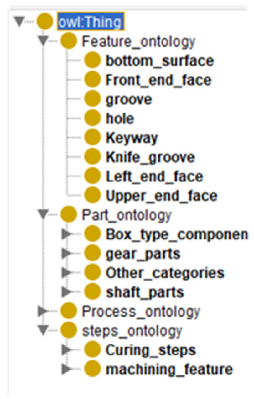
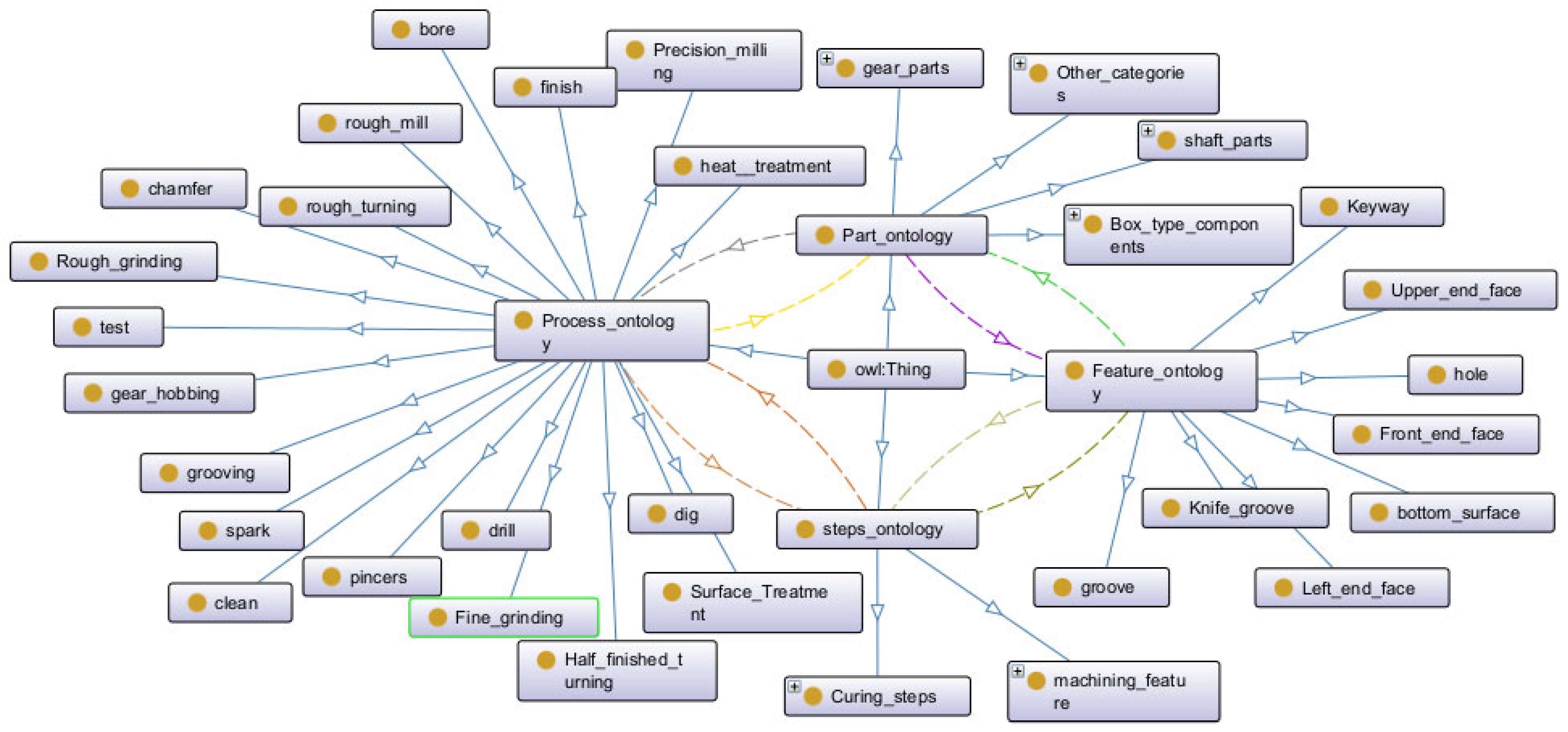
Using Protégé’s core components—classes, object properties and data properties—we populate the schema layer, ultimately saving the ontology construction results in OWL file format. This standardized format facilitates subsequent integration with the KG data layer through mapping relationships. Click the Onto graf plugin to visualize the schema layer, where distinct object properties are represented by differently colored dashed lines. The arrow direction indicates domain–range relationships: the starting point denotes the domain (subject), while the endpoint signifies the range (object), and illustrates the addition of attributes to the machining process knowledge graph’s part ontology, Figure 3 ontology, process ontology and operation ontology. Figure 4 demonstrates the addition of all data attributes to the knowledge graph. Figure 5 presents the visual representation of the schema layer for the machining process knowledge graph.

3.2. KG Data Layer Construction

The KG data layer implementation strictly adheres to the architectural framework predefined in the schema layer. Through extracting domain-specific ontological entities and their properties from heterogeneous data sources, followed by precise schema mapping, the abstract schema becomes concretely instantiated. This data layer construction workflow systematically comprises (1) structured entity extraction, (2) multi-source knowledge fusion and (3) ontology-aligned relationship construction.

3.2.1. Entity Extraction Based on Bi-LSTM-CRF Architecture

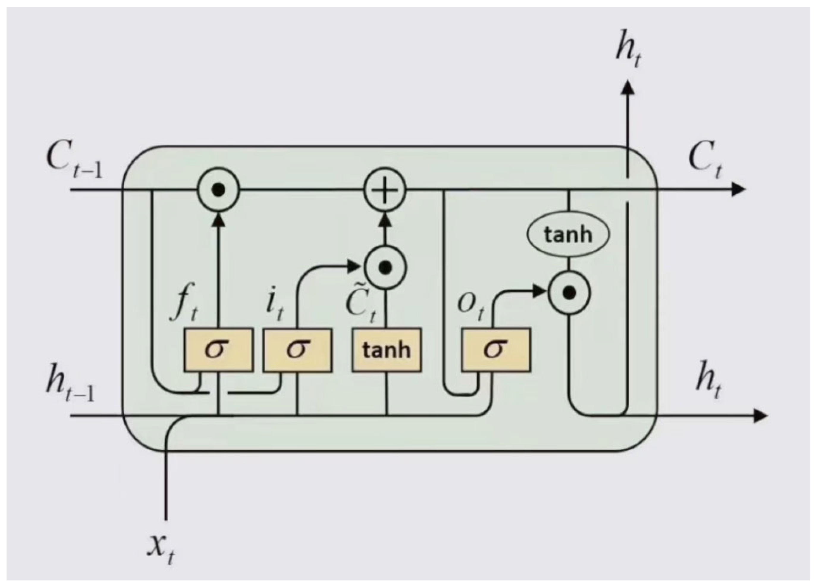
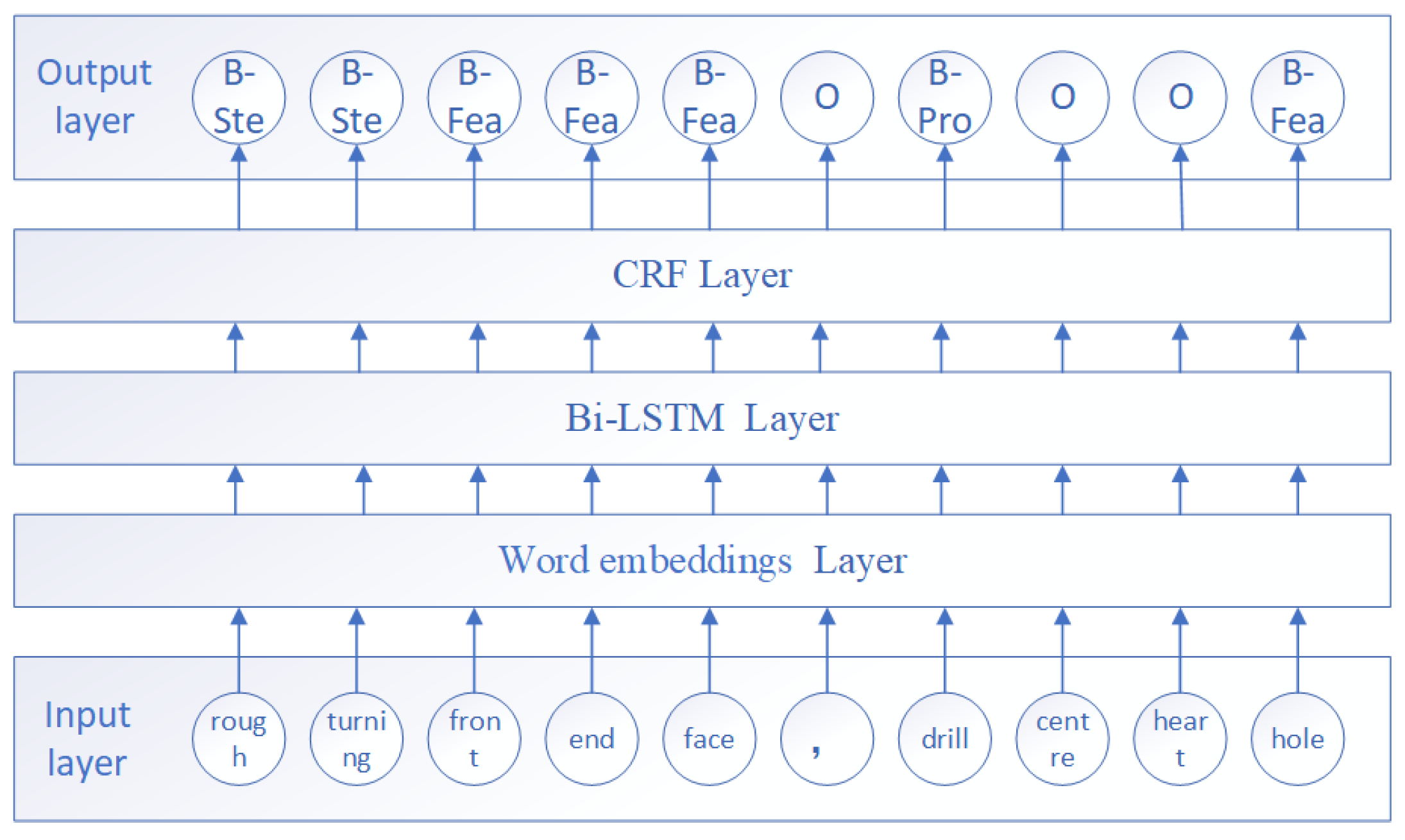
Entity extraction, or Named Entity Recognition (NER), primarily involves extracting triples from diverse process data sources and structural manufacturing data, which are then directly stored in the KG. The data sources used in this study are predominantly unstructured machining process cards from factories. For unstructured data, entity extraction typically employs (1) rule- and dictionary-based methods, (2) statistical machine learning approaches and (3) deep learning-based techniques. This research proposes a Bidirectional Long Short-Term Memory with Conditional Random Field (Bi-LSTM-CRF) architecture to enable precise entity extraction from machining process cards, facilitating the generation of a robust KG data layer through structured triple generation. Through bidirectional computation, Bi-LSTM achieves deeper contextual understanding of textual semantics, resulting in more accurate recognition performance. Figure 6 illustrates the structure of a single LSTM unit, while Figure 7 presents the architecture diagram of the Bi-LSTM-CRF network.
To effectively extract entities and their relationships from unstructured machining process cards for constructing the data layer of a machining PKG, the article will construct the data layer of the machining process knowledge graph through four key aspects: text preprocessing, entity extraction, relation extraction and entity alignment.
(1)
Textual Data Preparation: The unstructured documents representing machining process cards primarily contain string-formatted text. To facilitate computer recognition and algorithmic processing, the textual characters are first converted into numerical representations, typically by transforming words into fixed-dimensional numerical vectors. Word2Vec is a shallow, two-layer neural network and one of the most representative algorithms for distributed text representation. The Word2Vec model maps each word to a low-dimensional, dense vector that captures inter-word relationships, with these vectors constituting the hidden layer of the neural network. This distributed representation method calculates the similarity between words by measuring the distance between their corresponding vectors, effectively solving the dimensionality curse inherent in One-Hot encoding. Our study employs the Skip-gram model from the Word2Vec framework to generate word embeddings, ultimately producing a 300-dimensional vector representation.
(2)
Entity Extraction: In constructing the schema layer of the manufacturing process knowledge graph, we integrated four core entity types: part entity (e.g., gear), process entity (e.g., rough turning), operation step entity (e.g., rough turning of outer circle), feature entity (e.g., outer circle). The BIO (Begin-Inside-Outside) annotation framework was implemented with the following tags: B-Par (Begin-Part), B-Pro (Begin-Process), B-Ste (Begin-Step), B-Fea (Begin-Feature), O (Outside/non-entity). This tagging strategy enables subsequent entity recognition where (B- marks the initial character of entity keywords, I- denotes subsequent characters in multi-character entities, O- identifies non-entity terms). The complete annotation scheme is detailed in Table 2.
The entity extraction for machining process workflows is implemented using a Bi-LSTM + CRF network architecture. Long Short-Term Memory (LSTM) networks effectively address long-range dependency challenges, while the bidirectional LSTM (Bi-LSTM) enhances the model by processing sequences both forward and backward. This dual-directional processing captures contextual nuances more comprehensively, significantly improving recognition accuracy. In the encoding phase, a Bi-LSTM network processes the word vectors from the embedding layer. The Conditional Random Field (CRF), known for its accurate sequential dependency modeling, is then applied during decoding to refine the scores output by the Bi-LSTM, ensuring label sequence validity. Figure 8 illustrates the training structure of the Bi-LSTM-CRF network applied to a sample retrieved part.
In Figure 8, the input machining process for the queried part is specified as “Rough turning of the front-end face; drilling of the center hole”. Through the Skip-gram model, the text undergoes word vectorization, ultimately outputting the hidden layer representation for each term. The hidden layer representations from the Word Embeddings layer serve as input to the BiLSTM layer, where bidirectional LSTM units capture contextual features from both preceding and succeeding text. This outputs contextualized word representations that integrate information from the entire sequence. The BiLSTM’s outputs are then fed into the CRF layer to map to the label space, generating scores for each word-label pair. Through Conditional Random Field optimization, the model predicts the globally optimal label sequence, ultimately producing the final annotation results.
The extracted part entities, process entities, operation step entities and feature entities are stored in a MySQL database with dedicated relational tables. Table 3 presents the part instances stored in the MySQL database, while Table 4 displays the feature instances within the same database system.
(3)
Relation Extraction (RE) serves as a pivotal natural language processing (NLP) task that identifies and classifies semantic relationships between predefined entity pairs within textual data.
(4)
Entity Alignment is required to resolve duplicated and erroneous entities generated by the aforementioned extraction models. As process documents are authored by different manufacturing engineers, standardization of entity nomenclature cannot be guaranteed. The extracted entities may exhibit coreference issues, where surface orientation descriptors (e.g., “upper surface” vs. “lower surface”) or process granularity terms (e.g., “turning” vs. “rough turning”) refer to the same conceptual entity. Knowledge fusion resolves conceptual ambiguities, eliminates duplicates and corrects erroneous information to ensure KG quality. This process transforms extracted entities into validated triples. Given that machining process ontology attributes are primarily short-text descriptors, this study employs Jaccard similarity coefficient and Levenshtein distance for attribute-level similarity computation.
Jaccard coefficient refers to the method of expressing string similarity in the form of two sets; the closer the Jaccard coefficient is to 1, it indicates that the more common elements between the attributes of two entities, the higher the similarity. Minimum edit distance refers to the minimum number of edits required to convert a string into another string; editing operations include replacement, insertion and deletion; the smaller the edit distance, the greater the similarity between the two strings.
s and t stand for two short texts, the Jaccard coefficient formula:
S 1 = S T S T
In the formula, S and T denote the set of short texts (i.e., the set of entity attributes) of the two entities, where S T denotes the number of elements that are the same in the two text sets, and S T denotes the total of all strings in the two text sets.
Levenshtein’s minimum edit distance formula:
d i , j = 0 , i = 0   o r   j = 0 m i n d i 1 , j + 1 , d i , j 1 + 1 , d i 1 , j 1   ( x i = y i   ) m i n d i 1 , j + 1 , d i , j 1 + 1 , d i 1 , j 1 + 1           ( x i y i   )
represents the string t inserting a letter; represents the string s deleting a letter, and then when no cost is required, the same cost as the previous step, otherwise +1, is the smallest of the three above. The attribute similarity between entities, computed using Levenshtein edit distance, can be expressed as
S 2 = 1 1 + d m , n
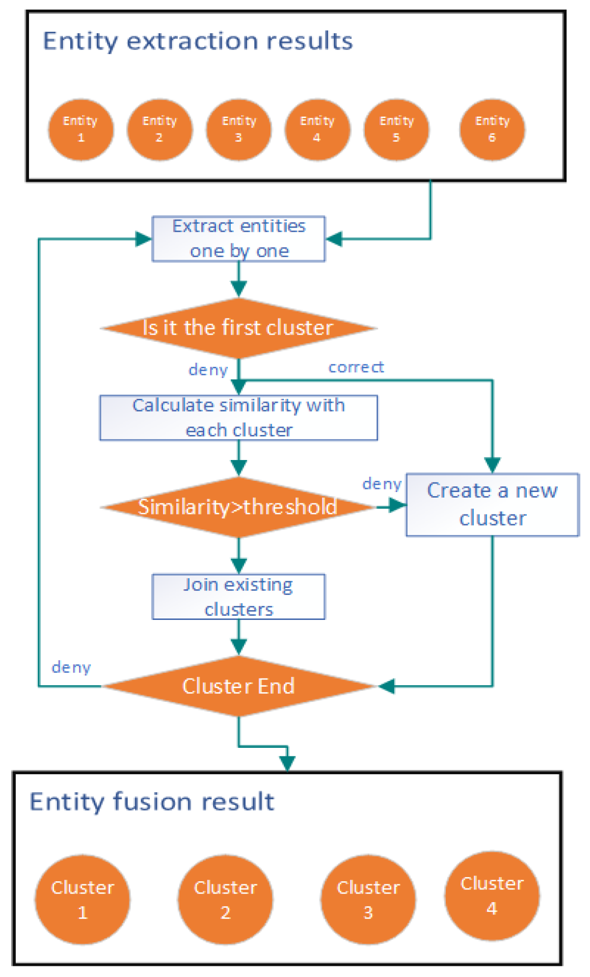
The entity alignment flowchart is shown in Figure 9.
In Figure 9, first take out the entities one by one for their own category query. For example, the upper end face belongs to the feature ontology; query whether there is an entity of the type upper end face. If not, the feature ontology class upper end face entities are recorded, and if the feature ontology class entities already exist, the attribute similarity is calculated with the existing feature ontology class entities, and the entities whose attribute similarity is greater than the threshold are added to the existing clusters; otherwise new clusters are created.
Table 5 presents examples of attribute similarity calculations for entities in the machining process of mechanical parts.
The computational results show that while the Jaccard similarity between “rough turning” and “turning” is 0.33, their Levenshtein edit distance similarity reaches 0.5. However, both “rough turning” and “turning” represent the same machining operation. Consequently, the attribute similarity between entities is derived by computing a weighted sum of the Jaccard similarity and Levenshtein edit distance similarity metrics.
S = ω 1 · S 1 + ω 2 · S 2
In the formula, S denotes the attribute similarity between entities, where ω 1 and ω 2 represent the weights assigned to the Jaccard similarity and Levenshtein edit distance similarity, respectively. The weights are configured as ω1 is set to 0.4 and ω2 is set to 0.6. After obtaining the entity similarity scores, a threshold comparison is performed (similarity threshold is set to 0.5). If the similarity threshold is satisfied, entity substitution is executed.
The entities consolidated through the aforementioned methods are stored in a MySQL database.

3.2.2. Ontological Relationship Construction

Due to the lack of explicit relationship descriptions in machining process cards, the four types of extracted ontological instances (parts, processes, steps and features) require systematic relationship construction. This is achieved by aligning them with the predefined object properties in the schema layer, followed by storage in a MySQL database. Here, the “parts have characteristics” relationship table, as an example, is shown in Table 6:

3.3. Knowledge Storage

The main storage methods for KG and their advantages and disadvantages are shown in Table 7 [28].
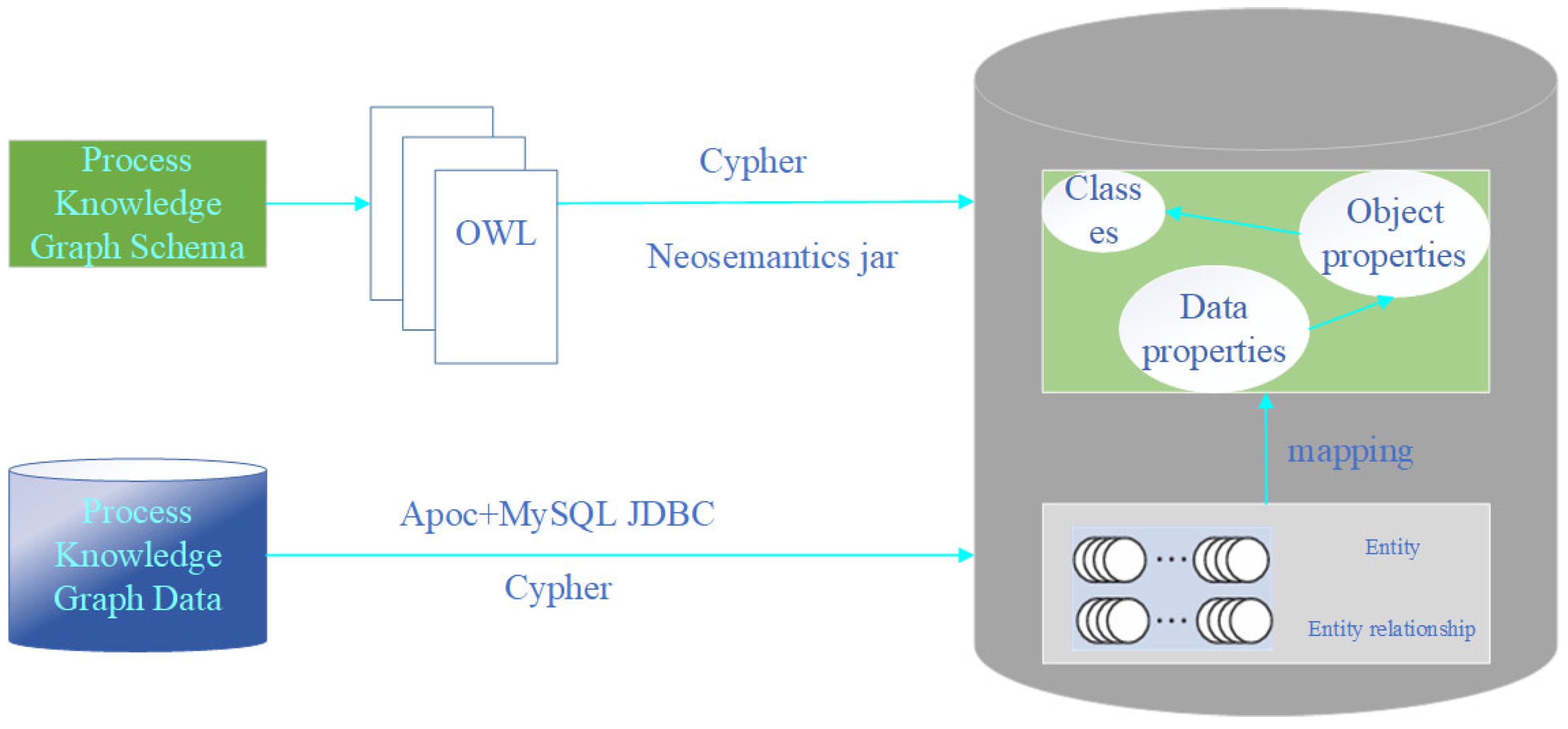
Leveraging the mature technical architecture and efficient global data operations of relational databases, combined with the superior search and query capabilities of graph databases [29], this study employs MySQL for storing extracted ontological instances and Neo4j for KG visualization. The knowledge storage pathway and methodology are illustrated in Figure 10.
Specifically, it consists of two parts: the import schema layer and the data layer:
(1)
Importing Schema Layer to Neo4j Database
Export the schema layer as an OWL file and import it into the Neo4j database using the neosemanticsjar tool to create the class node and the relationship node Cypher statement in Neo4j import the following CALLsemantics.liteOntoImport.
(2)
Import the data layer into the Neo4j database
The apoc plug-in in Neo4j and MySQL JDBC driver are used to realize the connection and data transfer function between Neo4j and MySQL database, and to establish all kinds of entity nodes, entity relationships and attributes in Neo4j. Connect MySQL database with Neo4j Cypher statement is as follows: Call apoc.load.driver (“com.mysql.jdbc.Driver”).

3.4. Knowledge Updating

The purpose of constructing a KG for common part machining processes is to enable enterprise process engineers to reuse this data more rapidly and effectively when designing new processes. However, the current KG cannot encompass all parts and their associated machining knowledge. With the rapid development of manufacturing, more complex non-standard parts will emerge. Therefore, this study proposes regular systematic updates to the process knowledge based on the established machining KG. Since the graph comprises both a schema layer and a data layer, updates should be applied to process information in each layer respectively, as illustrated in Figure 11.
(1)
Updates to the schema layer
For schema layer updates, the primary operations involve adding, deleting or modifying objects, subjects and properties. The updated file is saved as a new OWL file and imported into the Neo4j graph database using Cypher statements to generate new nodes.
(2)
Updates to the data layer
Updates to the data layer primarily involve modifications to entities, entity relationships and attribute values. For small-scale knowledge updates, Cypher statements can be directly executed in the Neo4j graph database. For large-scale updates, the extracted entity results should be saved as CSV files, and the triples are then imported into the graph database using Neo4j’s import tool to update nodes and relationships.

4. Application of KG for Machining Process

4.1. Visual Presentation of the KG

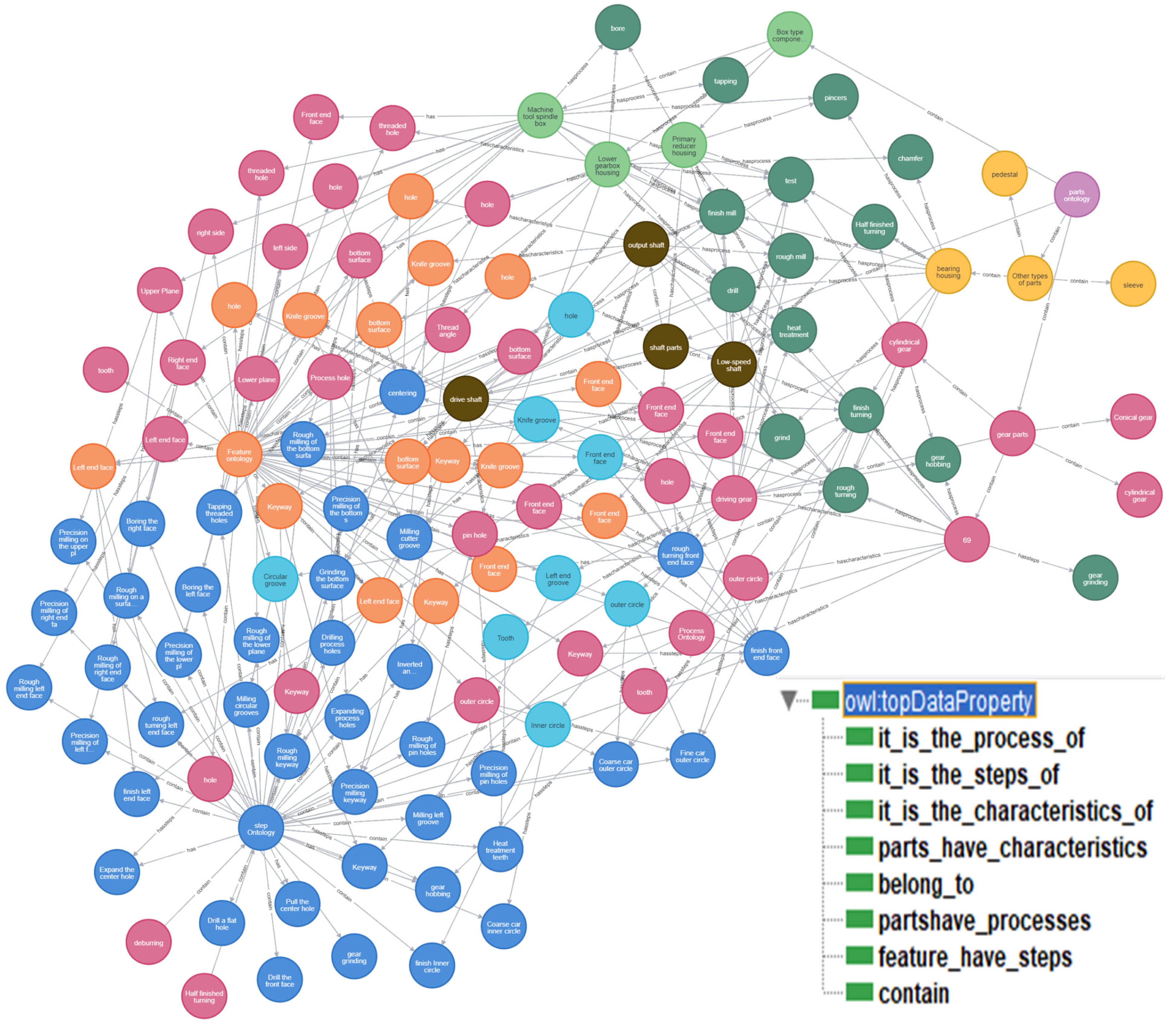
Based on the proposed methodology for building a KG of common part machining processes, knowledge extraction was performed on 12 machining process cards, followed by schema-data layer mapping. This resulted in 180 nodes and 432 entity relationships.
The triple data were imported into the Neo4j graph database, forming a visualized machining PKG. An example of part-associated information is illustrated in Figure 12.

4.2. Process Knowledge Retrieval Based on KG

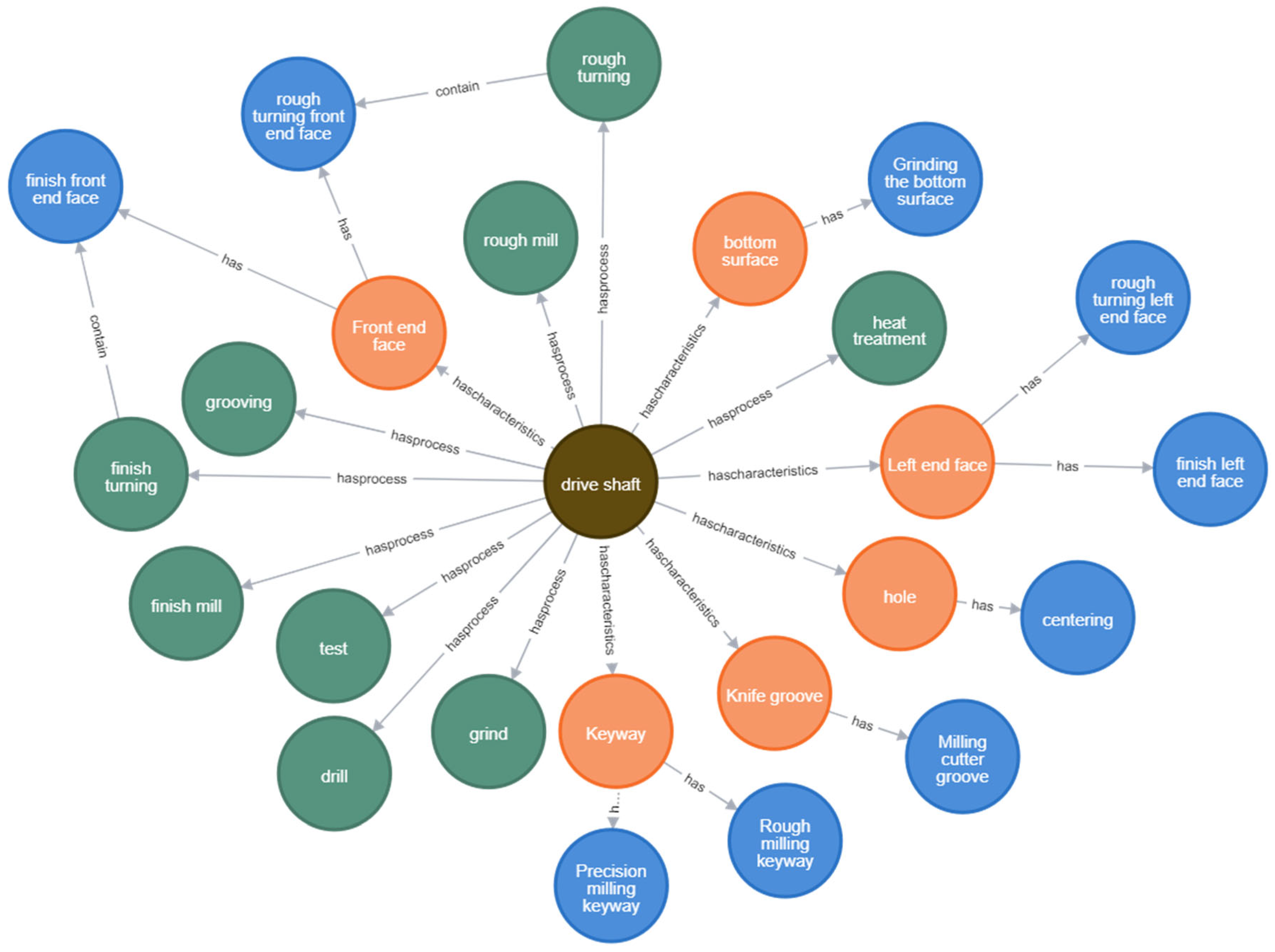
Traditional information retrieval relies on keyword matching, which only surfaces literal text-level results without capturing underlying semantic relationships [30]. In contrast, KGs represent information as interconnected entities, enabling to “drive shaft” as an example, when the process personnel need to query information about the machining process of a drive shaft part, you can use the Cypher language input MATCH p = (n: part example {part name: ‘drive shaft’})<-[r]->(m) RETURN p. The drive shaft part information is shown in Figure 13. According to the part information in Figure 13, we can double-click the node to view the processing information associated with it. For example, the part has a feature, the part has a process, the process has a work step, the feature has a work step, the work step contains a process and so on. As a result, we only need to search for the name of the part to obtain the relevant machining process information of the part, greatly improving the search efficiency and depth of information association, as shown in Figure 14, to show the results of the process information query as an example of the characteristics of the drive shaft part information.

4.3. Process Route Recommendation Based on KG

Part machining process route is the overall planning of part production, which directly affects the quality of parts and production efficiency [31]. Enterprises have strict requirements for the planning of process routes for complex and commonly used parts such as boxes and gears, and KG can better relate the knowledge. Therefore, the accurate recommendation of process routes based on the KG can not only assist the process personnel in the process design of new products, but also substantially improve the production efficiency of the enterprise.

4.3.1. Similarity Calculation

Based on the thinking and historical experience of the company’s craftspeople in designing new products, it can be assumed that the more similar the process route between two parts, the more similar the two parts are. Therefore, a similarity algorithm model can be used to calculate the similarity between the new part and the parts saved in the KG, set a certain threshold and recommend the part process routes with a similarity greater than the threshold to the craftsmen. The commonly used methods for calculating text similarity are Euclidean distance, cosine distance and Jaccard coefficient. Part ontology, process ontology, step ontology and feature ontology saved during construction are based on the 2.1 schema layer. Word2vec word vector model is used to obtain each part name word vector and cosine similarity is used to calculate the similarity of two-part space vectors.
Assuming that the coordinate of the vector s of part S in the space is x 1 , y 1 , and the coordinate of the vector t of part T in the space is x 2 , y 2 , the cosine similarity between S and T is calculated by the equation
cos θ = S · T S · T
S · T denotes the dot product operation of two vectors in space, S and T are the two-paradigm numbers of the two vectors, and θ denotes the angle between s and t. cos ( θ ) denotes the similarity value between the part S and the part T, and the smaller the θ is the closer the cos ( θ ) is to 1, which denotes that the similarity between the two parts is higher.
This indicates that the features of the part are all in the form of a collection of labels, the Jaccard coefficient is utilized to compare the similarity of two part attribute label collections, the larger the coefficient, the higher the similarity of the two sample sets.
Assuming that the set of attribute labels of part S is S m and the set of attribute labels of part T is T n , the Jaccard similarity formula is
J S m , T n = S m T n S m T n
where | S m T n | denotes the number of elements that are the same in both text collections and | S m T n | denotes the sum of all strings in both text collections.
Where ω 1 denotes the number of elements that are the same in both text collections and ω 2 denotes the sum of all strings in both text collections,
S = ω 1 · cos θ 1 + ω 2 · J S m , T n
The above equation ω 1 + ω 2 = 1 where ω 1 is the similarity weight of the part name and ω 2 is the similarity weight of the part attribute label (ω1 is set to 0.4, ω2 is set to 0.6), a certain similarity threshold is selected after the calculation (similarity threshold is set to 0.5), and the machining process route of the part based on the KG that is greater than the similarity threshold is recommended to the enterprise craftsmen.

4.3.2. Analyze the Results of the Recommendations

After constructing the machining PKG, a machining process knowledge base is also obtained. Therefore, the process route recommendation can be performed based on the KG, and the process route of the target part is obtained by calculating the cosine similarity and Jaccard similarity.
(1)
Experimental data selection
Shaft parts are especially widely used in the field of production and processing, and the machining process route is not simple. Therefore, shaft parts are selected as the experimental validation object to validate the process route recommendation based on KG. The relevant information of the drive shaft is shown in Table 8.
(2)
Results of the recommended process route based on mapping
Taking the drive shaft as the target part, input the drive shaft part information in the similarity algorithm model, the recommended list data obtained is shown in Table 9, and the specific recommendation score is shown in Figure 15.
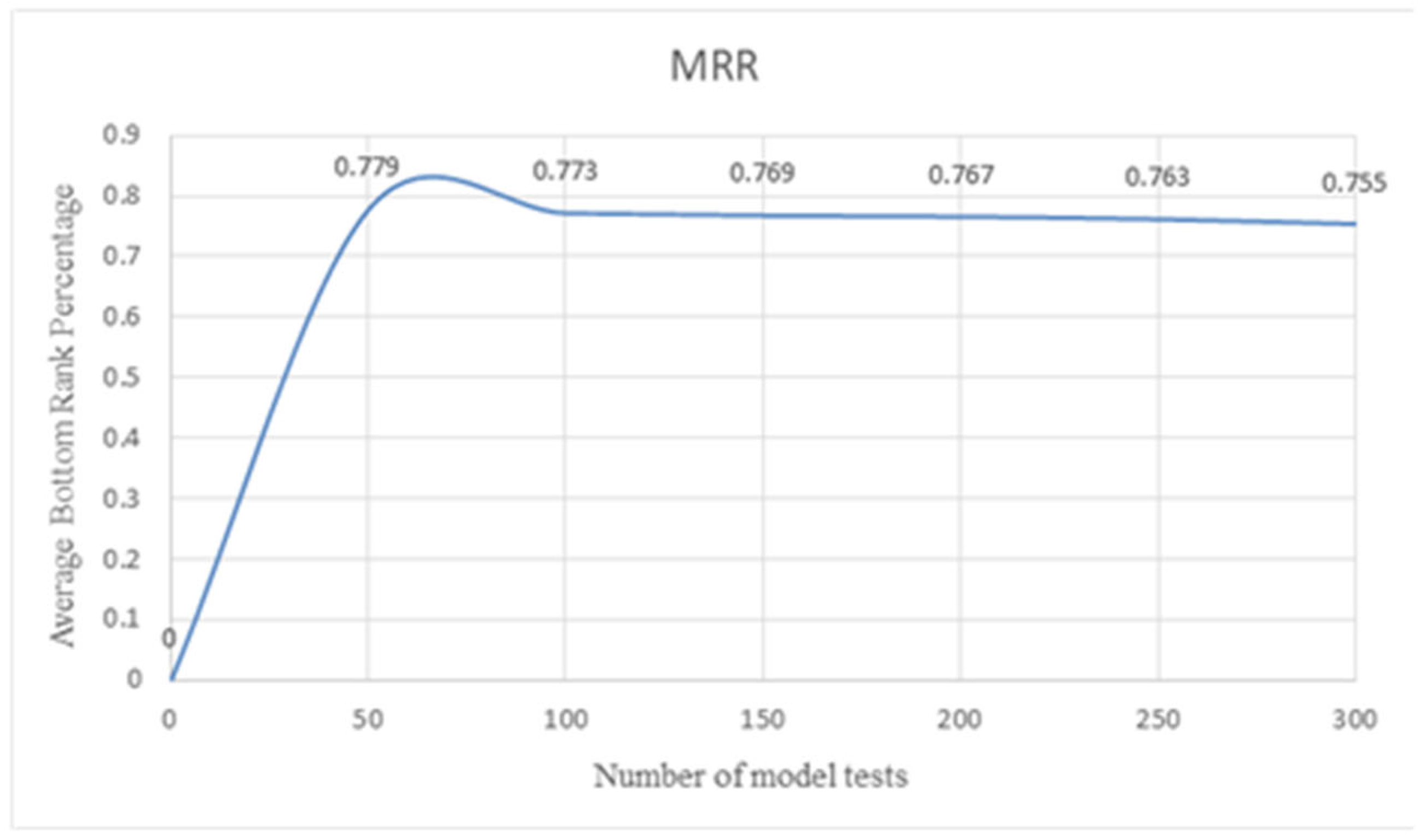
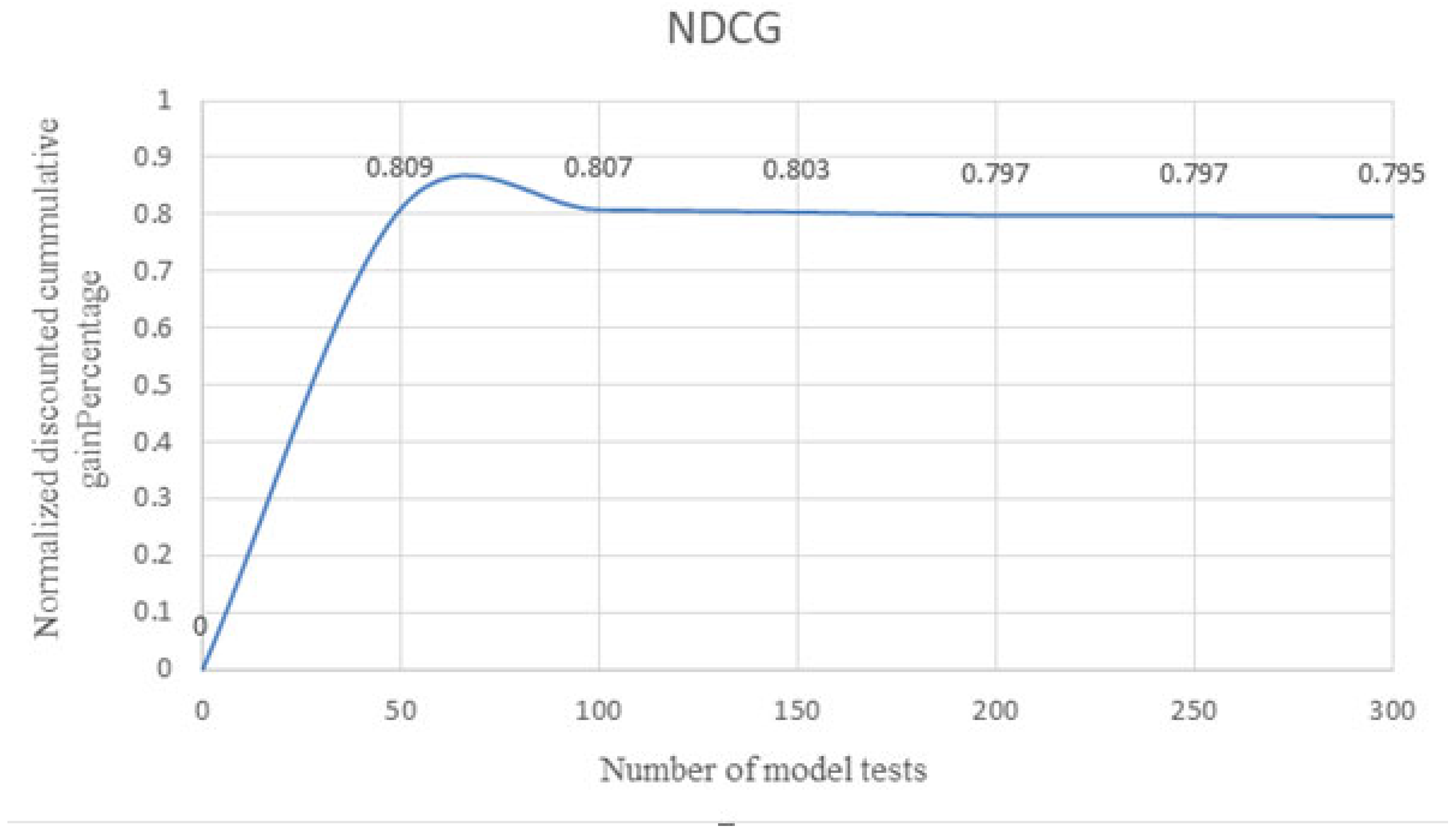
In order to re-verify the similarity algorithm model recommendation results reasonableness and reliability, the recommendation model was tested 300 times to HR (Hit Rate), MRR (Mean Reciprocal Rank), NDCG (Normalized Discounted Cumulative Gain), three metrics to evaluate the model.
HR represents the accuracy rate of the recommendation result, i.e., whether the process route of the target part exists in the recommended list calculated by the similarity algorithm model. Its calculation formula is as follows:
H R = 1 N i = 0 N h i t i
In the formula, N indicates the total number of tests, hit(i) indicates the target part process route i in the recommended list after calculation, if the target part process route hit(i) exists in the recommended list, it is 1, and if it does not exist, it is 0.
MRR indicates the specific sequential position of the process route of the target part in the recommended list by calculation. The formula is as follows:
M R R = 1 N i = 1 N 1 r a n k i
where rank(i) is the position where the process route of the target part appears in the recommended result through the calculation, if it appears, rank(i) is 1, otherwise rank(i) is +∞.
NDCG is used to indicate whether the result of the recommendation list is excellent or not through the calculation, i.e., whether the recommendation score through the similarity model matches the actual situation. The formula is as follows:
D C G = D C G I D C G = i = 1 N r e l i log 2 i + 1 I D C G
In the formula, DCG (Discounted Cumulative Gain), it will calculate the gain based on the relevance score of the item and its position in the list, rel (i) indicates that the relevance is scored artificially. Scores are assigned on a scale of 0 to 3. The higher the position (i.e., the earlier in the ranking), the higher the score, indicating greater relevance and higher gain (0 means completely irrelevant, 1 means weakly relevant, 2 means relevant, and 3 means completely relevant). IDCG (Ideal Discounted Cumulative Gain) is the DCG calculated by ranking the real relevance scores in order from high to low. Finally, NDCG is the result of dividing DCG by IDCG to obtain the normalized result, which ranges from 0 to 1. The closer the value is to 1 means that the recommendation list is closer to the ideal ordering.
Based on similarity algorithm model testing, the evaluation results of the recommendation model are as follows: HR shown in Figure 16 demonstrates that when calculated at every 50-step interval, the accuracy consistently exceeds 0.9. This indicates that over 90% of recommendation lists contain process routes matching the target component. MRR shown in Figure 17 reveals that when computed at 50-step intervals, the data confirm matching process routes predominantly appear in top positions of recommendation lists. NDCG shown in Figure 18 illustrates that periodic calculations at 50-step intervals show ground truth rankings align perfectly with model-generated rankings in most cases.
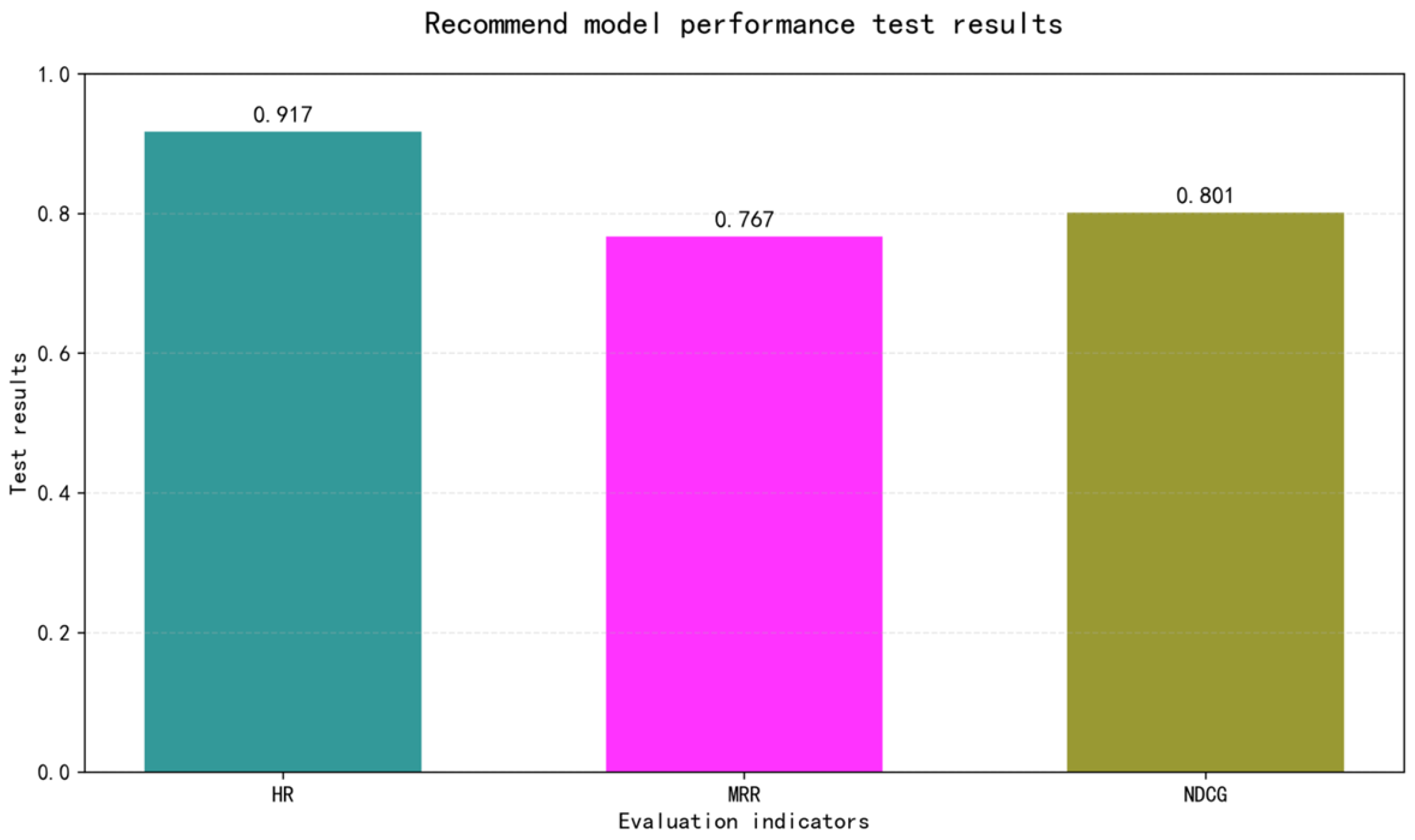
After organizing the data in Figure 16, Figure 17 and Figure 18, the recommendation algorithm score evaluation metrics HR, MRR and NDCG are obtained, as shown in Figure 19.
In Figure 19, HR is 0.917, indicating that 91.7% of the process routes in the recommended list match the target part; MRR is 0.767, indicating that most of the cases in which the recommended list matches the process routes of the target part appear at the top of the recommended list; and NDCG is 0.801, indicating that the results of the process routes in the recommended list that match the target part are consistent with the process routes in the recommended list under the scoring based on relevance.
In the similarity algorithm, the recommended model test will also appear in the comprehensive similarity of the parts process route and in the actual process route of the target parts there are differences in the situation, and in a comprehensive analysis, the biggest reason is that most of the cases of the enterprise’s process personnel according to their own experience in the design of process routes, however, differences in the design skills and ideas of each process engineer result in a low degree of standardization in process design. Therefore, the process route with the highest score recommended by the similarity algorithm model may not necessarily be the most suitable process route.
Overall, the process route recommendation based on the KG has a certain guiding effect on the enterprise process personnel to design a new parts process, which can significantly reduce the design time of the process personnel and improve the work efficiency.

5. Concluding Remarks

The article on how to efficiently correlate and reuse historical process data within the enterprise sharing problems proposed a top-down and bottom-up combination of a parts machining PKG construction method, and through the similarity algorithm model, achieves the new parts of the process route recommendation.
The research is based on the following three points:
(1)
The KG schema layer and the KG data layer are mapped to each other in the Neo4j graph database to obtain a visualized KG of the parts machining process, which reduces data redundancy and improves retrieval efficiency;
(2)
Through the combination of top-down and bottom-up methods combined with deep learning technology, a more accurate KG of part machining process is obtained, and the process knowledge retrieval based on the graph is realized;
(3)
By comprehensively calculating the similarity of part attributes (cosine similarity and Jaccard similarity), the process route recommendation based on machining PKG is realized, and the accuracy of the recommendation reached 91.7%.
However, the article does not do enough in two areas:
(1)
The data for constructing the KG of part machining process come from the machining process card of the enterprise, which is a relatively single data source with insufficient coverage in the whole machining field, and the knowledge extraction algorithm will be further considered in the subsequent work to expand the coverage of the whole KG of machining process:
(2)
Although process knowledge retrieval and process route recommendation based on KG is simply accomplished, it does not fully demonstrate the more powerful reasoning capability of KGs. Therefore, in the subsequent work, the process knowledge reasoning through graph isomorphism, graph matching and other methods will be considered as the key content.

Author Contributions

Final draft review, L.L.; overall scheme design, C.L.; writing, J.L.; creating a chart, Z.L.; data analysis, Y.W.; literature search, Z.J.; data collection, Z.L. All authors have read and agreed to the published version of the manuscript.

Funding

The Key Research and Development Program of Shaanxi (Program No. 2024GX-YBXM-116), China, C.L.

Data Availability Statement

The data are already included in the paper. The authors are available for contact if needed. All data used are included in the paper, as stated in our data availability statement.

Conflicts of Interest

The authors declare no conflicts of interest.

Abbreviations

KGKnowledge graph
PKGProcess Knowledge graph
PKGSProcess Knowledge graph Schema
PKGDProcess Knowledge graph Data
e.g.exempli gratia
NERNamed Entity Recognition
LSTMLong Short-Term Memory
Bi-LSTM-CRFBidirectional Long Short-Term Memory with Conditional Random Field
BIOBegin-Inside-Outside
RERelation Extraction RE
HRHit Rate
MRRMean Reciprocal Rank
NDCGNormalized Discounted Cumulative Gain
DCGDCG Discounted Cumulative Gain
IDCGIdeal Discounted Cumulative Gain

References

  1. Li, C.L. Research on Intelligent Decision-Making and Process Reuse for Machining Process Design. Ph.D. Thesis, Northwestern Polytechnical University, Shaanxi, China, 2017. [Google Scholar]
  2. Chhim, P.; Chinnam, R.B.; Sadawi, N. Product design and manufacturing process based ontology for manufacturing knowledge reuse. J. Intell. Manuf. 2019, 30, 905–916. [Google Scholar] [CrossRef]
  3. Song, L.W. Analysis of Hotspots and Frontiers in Google KG and Improvement Research on Co-Word Network Clustering. Ph.D. Thesis, University of Science and Technology of China, Hefei, China, 2019. [Google Scholar]
  4. Zheng, P.; Xia, L.; Li, C.; Li, X.; Liu, B. Towards Self-X cognitive manufacturing network: An industrial KG-based multi-agent reinforcement learning approach. J. Manuf. Syst. 2021, 61, 16–26. [Google Scholar] [CrossRef]
  5. Li, X.L.; Zhang, S.S.; Huang, R. Construction Method of PKG for Process Reuse. J. Northwest. Polytech. Univ. 2019, 37, 1174–1183. [Google Scholar] [CrossRef]
  6. Li, J.X.; Qu, Y.N.; Qiu, H.H.; Liu, B.; Li, L.; Zhang, J.; Wei, L. Machining Process Design Method for Parts Based on KG and Deep Learning. Comput. Integr. Manuf. Syst. 2024, 30, 3850–3865. [Google Scholar] [CrossRef]
  7. Wang, L.; Cheng, H.; Wang, R.; Huang, X. Machining Scheme Selection of Features Based on PKG and Improved Cosine Similarity Matching. Machines 2025, 13, 188. [Google Scholar] [CrossRef]
  8. Jiang, Z.G.; Xie, B.; Zhu, S.; Zhang, H.; Yan, W.; Dai, M. Dynamic Data Flow-Driven KG Construction Method for Remanufacturing Disassembly Process. Comput. Integr. Manuf. Syst. 2024, 30, 879–892. [Google Scholar] [CrossRef]
  9. Duan, Y.; Hou, L.; Leng, S. Construction and Application of KG for Metal Cutting. J. Jilin Univ. (Eng. Technol. Ed.) 2021, 51, 122–133. [Google Scholar]
  10. Nie, T.; Zeng, J.; Cheng, Y.; Ma, L. KG Construction Technology and Its Application in Aircraft Power System Fault Diagnosis. Acta Aeronaut. Astronaut. Sin. 2021, 42, 1–19. [Google Scholar]
  11. Chen, X.; Xiang, Y. Construction and Application of Enterprise Risk KG. Comput. Sci. 2020, 47, 237–243. [Google Scholar]
  12. Hu, Z.Q.; Liu, M.F.; Li, Q.; Li, X.Y.; Bao, J.S. Modeling of Multi-Modal KG for Assembly Process of Wind Turbines with Multi-Source Heterogeneous Data. J. Shanghai Jiao Tong Univ. 2023, 57, 297–306. [Google Scholar] [CrossRef]
  13. Rospocher, M.; van Erp, M.; Vossen, P.; Fokkens, A.; Aldabe, I.; Rigau, G.; Soroa, A.; Ploeger, T.; Bogaard, T. Building Event-Centric KG from News. Web Semant. Sci. Serv. Agents World Wide Web 2016, 37–38, 132–151. [Google Scholar] [CrossRef]
  14. Rotmensch, M.; Halpern, Y.; Tlimat, A.; Horng, S.; Sontag, D. Learning a Health Knowledge Graph from Electronic Medical Records. Sci. Rep. 2017, 7, 5994. [Google Scholar] [CrossRef]
  15. Li, J.Z.; Hou, L. Review on KG Research. J. Shanxi Univ. (Nat. Sci. Ed.) 2017, 40, 454–459. [Google Scholar] [CrossRef]
  16. Tao, J.Q.; Li, X.Y.; Zheng, P.; Peng, T.; Xu, K.; Jing, B. State-of-Art and Frontier of Manufacturing KG Application. Comput. Integr. Manuf. Syst. 2022, 28, 3720–3736. [Google Scholar]
  17. Shen, T.; Zhang, F.; Cheng, J.W. A Comprehensive Overview of KG Completion. Knowl. Based Syst. 2022, 255, 109597. [Google Scholar] [CrossRef]
  18. Xu, Q.; Niu, N.; Quan, Y.; Jin, Z. Research on the Development of Text Mining Technology Based on Bibliometrics and Knowledge Map Visualization. Sci. J. Inf. Eng. 2017, 7, 51–52. [Google Scholar]
  19. Xu, Z.L.; Sheng, Y.P.; He, L.R.; Wang, Y. Review on KG Techniques. J. Univ. Electron. Sci. Technol. China 2016, 45, 589–606. [Google Scholar]
  20. Yang, Y.J.; Xu, B.; Hu, J.W.; Tong, M.; Zhang, P. An Accurate and Efficient Construction Method for Domain KG. J. Softw. 2018, 29, 2931–2947. [Google Scholar]
  21. Brahimi, M. An Agents’ Model Using Ontologies and Web Services for Creating and Managing Virtual Enterprises. Int. J. Comput. Digit. Syst. 2019, 8, 9–15. [Google Scholar] [CrossRef]
  22. Yi, L.T.; Zhou, S.Q.; Ding, C.S. Research on Domain Ontology Modeling in Information Extraction. Comput. Technol. Dev. 2011, 21, 5. (In Chinese) [Google Scholar] [CrossRef]
  23. Martinez-Garcia, J.; Castillo-Barrera, F.E.; Palacio, R.; Borrego, G.; Cuevas-Tello, J.C. Ontology for Knowledge Condensation to Support Expertise Location in the Code Phase during Software Development Process. IET Softw. 2020, 14, 223–241. [Google Scholar] [CrossRef]
  24. Zhang, B.; Qian, P.; Li, C.; Gao, F.; Yang, N. Research on the Construction Method of Knowledge Ontology Facing the Field of Substation Maintenance. J. Phys. Conf. Ser. 2021, 1971, 012062. [Google Scholar] [CrossRef]
  25. Zhang, H.; Li, J.; Hong, M.; Man, Y.; He, Z. Cost Optimal Production-Scheduling Model Based on VNS-NSGA-II Hybrid Algorithm—Study on Tissue Paper Mill. Processes 2022, 10, 2072. [Google Scholar] [CrossRef]
  26. Zhang, Z.; He, X.; Man, Y.; He, Z. Multi-Objective Scheduling in Dynamic of Household Paper Workshop Considering Energy Consumption consumption in production process. J. Smart Environ. Green Comput. 2023, 3, 87–105. [Google Scholar] [CrossRef]
  27. Tian, L.; Zhang, J.C.; Zhang, J.H.; Zhou, W.; Zhou, X. KG Survey: Representation, Construction, Reasoning and Knowledge Hypergraph Theory. J. Comput. Appl. 2021, 41, 2161–2186. [Google Scholar]
  28. Kotiranta, P.; Junkkari, M.; Nummenmaa, J. Performance of Graph and Relational Databases in Complex Queries. Appl. Sci. 2022, 12, 6490. [Google Scholar] [CrossRef]
  29. Guo, R.; Yang, Q.; Liu, S.H.; Li, W.; Yuan, X.; Huang, X. Construction and Application of Power Grid Fault Handling KG. Power Syst. Technol. 2021, 45, 2092–2100. [Google Scholar]
  30. Guo, X.Y.; Wang, L.; Zhang, Y.J. Machining Process Planning Based on Immune Genetic Algorithm with Rule Constraints. China Mech. Eng. 2020, 31, 482–488. [Google Scholar]
  31. Han, C.C.; Li, L.; Liu, T.T.; Gao, M. Approaches for Semantic Textual Similarity. J. East China Norm. Univ. (Nat. Sci.) 2020, 5, 95–112. [Google Scholar] [CrossRef]
Figure 1. Framework diagram for construction and application of machining PKG for mechanical parts.
Electronics 14 03156 g001
Figure 2. PKG schema layer construction framework.
Electronics 14 03156 g002
Figure 3. Object properties.
Electronics 14 03156 g003
Figure 4. Date properties.
Electronics 14 03156 g004
Figure 5. Ontology relationship visualization.
Electronics 14 03156 g005
Figure 6. Structure of an LSTM unit.
Electronics 14 03156 g006
Figure 7. Architecture diagram of the Bi-LSTM-CRF network.
Electronics 14 03156 g007
Figure 8. The training structure of the Bi-LSTM-CRF network.
Electronics 14 03156 g008
Figure 9. Entity alignment flowchart.
Electronics 14 03156 g009
Figure 10. Knowledge storage paths and methods.
Electronics 14 03156 g010
Figure 11. KG update method.
Electronics 14 03156 g011
Figure 12. Visualization of the machining process KG (partial).
Electronics 14 03156 g012
Figure 13. Main shaft part information.
Electronics 14 03156 g013
Figure 14. Active axis feature association information.
Electronics 14 03156 g014
Figure 15. Process route recommendation score.
Electronics 14 03156 g015
Figure 16. Schematic diagram of HR changes.
Electronics 14 03156 g016
Figure 17. Schematic representation of MRR changes.
Electronics 14 03156 g017
Figure 18. Schematic diagram of NDCG changes.
Electronics 14 03156 g018
Figure 19. Schematic of evaluation indicator scores.
Electronics 14 03156 g019
Table 1. Difficulties in constructing PKG.
DifficultyTypology
Complexity of knowledge(1) There are many types of equipment and processes, and different equipment and processes can be used for the same process, making it difficult to establish relationships in a uniform manner.
(2) Equipment information is fragmented and disorganized, with knowledge of various equipment stored in different databases, online or offline documents, with a low level of structuring.
Lack of relevant data(1) Building a KG requires large labeled datasets. There are many types of processing industries, each with large amounts of data that are underutilized.
(2) Poor data interaction. Most plant data are stored only in the plant and is rarely used.
Difficulty of knowledge management(1) Experts are needed to manage the KG, which is very expensive to operate and manage.
(2) Devices change and improve rapidly, and the KG requires a mechanism to dynamically update knowledge.
Table 2. Entity labeling rules.
Entity TypeStart MarkerFollow-Up Marker
PartsB-ParI-Par
ProcessB-ProI-Pro
StepB-SteI-Ste
FeatureB-FeaI-Fea
Non-entityOO
Table 3. Part entity instances stored in MySQL database.
Par-IDPar-NamePar-Process
Par-1Drive ShaftRough Turning → Drilling → Rough Turning → Finish Turning → Grooving → Heat Treatment → Rough Milling → Finish Milling → Rough Grinding → Finish Grinding → Inspection
Par-2Low-Speed ShaftRough Turning → Drilling → Rough Turning → Semi-Finish Turning → Grooving → Heat Treatment → Finish Turning → Rough Milling → Finish Milling → Deburring → Inspection
Par-3Output ShaftRough Turning → Drilling → Rough Turning → Finish Turning → Heat Treatment → Rough Milling → Finish Milling → Deburring → Inspection
Par-4Drive GearHeat Treatment → Rough Turning → Heat Treatment → Finish Turning → Rough Milling → Finish Milling → Gear Hobbing → Heat Treatment → Deburring → Inspection
Par-5Cylindrical GearHole Enlarging → Hole Broaching → Rough Turning → Semi-Finish Turning → Gear Hobbing → Deburring → Hole Grinding → Chamfering → Inspection
Par-6Bevel GearHeat Treatment → Rough Turning → Finish Turning → Gear Milling → Hole Enlarging → Hole Broaching → Hole Grinding → Gear Grinding → Heat Treatment → Deburring → Inspection
Par-7Machine Tool Spindle HousingRough Turning → Finish Turning → Rough Milling → Finish Milling → Drilling → Boring → Tapping → Inspection
Par-8Reducer Lower HousingRough Milling → Finish Milling → Drilling → Pilot Hole Enlarging → Drilling → Tapping → Rough Boring → Semi-Finish Milling → Semi-Finish Boring → Finish Milling → Finish Boring → Center Drilling → Chamfering → Tapping → Final Inspection
Par-9First-Stage Reducer HousingHeat Treatment → Rough Milling → Rough Grinding → Finish Grinding → Finish Milling → Drilling → Boring → Tapping → Inspection
Par-10SleeveHeat Treatment → Rough Turning → Finish Turning → Drilling → Boring → Deburring → Heat Treatment → Rough Grinding → Finish Grinding → Deburring → Inspection
Par-11Bearing SeatBench Fitting → Rough Milling → Finish Milling → Rough Turning → Finish Turning → Rough Grinding → Finish Grinding → Drilling → Final Inspection
Par-12Shaft BracketHeat Treatment → Rough Milling → Finish Milling → Boring → Drilling → Hole Enlarging → Rough Milling → Finish Milling → Deburring → Inspection
Table 4. Feature entity instances stored in MySQL database.
Fea-IDFea-NameFea-Code
Fea-1Drive shaft—front end surfaceZDZ-qdm
Fea-2Drive shaft—hole featureZDZ-k
Fea-3Drive shaft—left end surfaceZDZ-zdm
Fea-4Drive shaft—tool relief grooveZDZ-dc
Fea-5Drive shaft—bottom surfaceZDZ-dm
Table 5. Similarity calculation examples.
(Process Card 1)(Process Card 2)Jaccard SimilarityLevenshtein Similarity
Upper SurfaceLower Surface0.6150.75
Rough TurningTurning0.330.5
Table 6. Characterized parts relationships stored in MySQL database.
Par-IDFea-ID
Par-1Fea-1
Par-1Fea-2
Par-2Fea-6
Par-2Fea-7
Table 7. Comparison of three KG storage methods and their advantages and disadvantages.
Relational DatabaseRDF DatabaseGraph Database
Strengths: high storage efficiency, fast simple queries, easy maintenance Strengths: intuitive semantic representation, supports schema-based inferenceStrengths: high efficiency for deep traversal, optimized for relationship queries, scalable for complex networks
Weaknesses: poor join performance, limited real-time analytics, rigid schemaWeaknesses: low design flexibility, large storage footprint, slow complex queriesWeaknesses: high resource consumption
Table 8. Main shaft part information.
Part NameMaterialFeature InformationProcess Route
Drive Shaft45 SteelPlanar Surfaces, Holes, Tool Grooves, Keyways, Flats, ShouldersRough Turning → Drilling → Rough Turning → Finish Turning → Grooving → Heat Treatment → Rough Milling → Finish Milling → Rough Grinding → Finish Grinding → Inspection
Table 9. Recommended list of process routes for “drive shaft” parts.
No.Part NamePart IDProcess Route
1Drive ShaftPar-1Rough Turning → Drilling → Rough Turning → Finish Turning → Grooving → Heat Treatment → Rough Milling → Finish Milling → Rough Grinding → Finish Grinding → Inspection
2Low-Speed ShaftPar-2Rough Turning → Drilling → Rough Turning → Semi-Finish Turning → Grooving → Heat Treatment → Finish Turning → Rough Milling → Finish Milling → Deburring → Inspection
3Output ShaftPar-3Rough Turning → Drilling → Rough Turning → Finish Turning → Heat Treatment → Rough Milling → Finish Milling → Deburring → Inspection
Disclaimer/Publisher’s Note: The statements, opinions and data contained in all publications are solely those of the individual author(s) and contributor(s) and not of MDPI and/or the editor(s). MDPI and/or the editor(s) disclaim responsibility for any injury to people or property resulting from any ideas, methods, instructions or products referred to in the content.