Article

Parameter Identification Method of Grid-Forming Static Var Generator Based on Trajectory Sensitivity and Proximal Policy Optimization Algorithm

1
State Grid Sichuan Electric Power Research Institute, Chengdu 610041, China
2
College of Electrical Engineering, Sichuan University, Chengdu 610065, China
*
Author to whom correspondence should be addressed.
Electronics 2025, 14(15), 3119; https://doi.org/10.3390/electronics14153119
Submission received: 21 July 2025 / Revised: 2 August 2025 / Accepted: 4 August 2025 / Published: 5 August 2025

Abstract

As the penetration rate of new energy continues to increase, the active voltage support capability of the power system is decreasing. The grid-forming static var generator (GFM-SVG) features the advantages of fast dynamic response, strong reactive power support, and high overload capacity, which play an important role in maintaining voltage stability. However, the parameters of the GFM-SVG are often unknown due to trade secret reasons. Meanwhile, the parameters may be changed during the long-term operation of the system, which brings challenges to the system stability analysis and control. Aiming at this problem, a parameter identification method based on trajectory sensitivity analysis and the proximal policy optimization (PPO) algorithm is proposed in this paper. Firstly, through trajectory sensitivity analysis, the key influential parameters on the output characteristics of the GFM-SVG can be selected, which can reduce the dimensionality of the identification parameters and improve the identification efficiency. Then, a parameter identification framework based on the PPO algorithm is constructed for GFM-SVGs, which utilizes its adaptive learning capability to achieve accurate identification of the key parameters of the system. Finally, the effectiveness of the proposed parameter identification method is verified through simulation examples. The simulation results show that the identification error of the parameters in the GFM-SVG is small. The proposed method can characterize the output response of the GFM-SVG under different operating conditions.

1. Introduction

With the rapid development of global power systems, highly interconnected power grids and long-distance and large-scale power transmission have become the norm [1,2]. Load center grids are highly dependent on large-scale, long-distance power transmission power supply mode, which leads to the formation of a high proportion of receiving load center grids with a high degree of “power hollowing out” characteristics [3]. In the context of the high proportion of new energy sources such as photovoltaic and wind power connected to the power system, their weak anti-interference ability leads to a continuous decline in the inertia and damping of the power system [4,5]. This has led to a serious lack of dynamic reactive power and an increasing risk of transient voltage instability in the high proportion of receiving power “power hollowing out” grid [6,7]. At present, the lack of voltage support capacity has gradually become an important factor restricting the receiving capacity of large urban grids as well as the ability of large-scale new energy transmission [8].
At present, most of the dynamic reactive power compensation devices commonly used in power systems are static var compensators (SVC), conventional SVGs, and synchronous compensators [9,10]. However, there are shortages among the above reactive power compensation devices in terms of response speed, overload capability, and active support capability, which makes it difficult to solve the transient voltage instability problem in load center grids. Aiming at the deficiencies of the existing devices, the grid-forming static var generator (GFM-SVG) proposed by academia and industry has the advantages of fast dynamic response speed and high overload capability. This enables transient response characteristics with essentially no delay, and thus it is a completely new means to improve the voltage support capability of the grid [11]. In June 2024, the first grid-side GFM-SVG independently developed by the State Grid of China was put into operation in Sichuan Province, which effectively enhanced the power transmission capacity of the regional grid.
The GFM-SVG simulates the operating mechanism of a synchronous generator, which provides reactive power compensation and inertia support to the grid. This is a key support device for low-inertia power systems. With the wide application of GFM-SVG, it is necessary to perform stability analysis and control of it after it is connected to the power grid, and thus its parameters need to be accurately obtained [12]. The GFM-SVG contains multiple control links, such as a power control loop and a direct current (DC) synchronization loop. There is a coupling relationship between multiple control links [13,14]. In actual operation, due to changes in the operating environment, equipment aging, control strategy switching, etc., the parameters are prone to change [15]. For the changing parameters, it is necessary to accurately identify the key parameters of the GFM-SVG. This is important to ensure its control effect and optimize system stability.
There are no parameter identification methods for GFM-SVGs based on DC synchronous and virtual impedance in existing studies. A particle swarm algorithm-based SVG controller parameter identification method is proposed in [16], and hardware-in-the-loop testing is carried out on real time digital simulation system (RTDS), but this type of swarm intelligent optimization algorithm is prone to falling into a local optimum. Based on the system measurement data, the parameters of the grid-following SVG are recognized in [17], but the complexity of the calculation of this algorithm is high. For the stochastic output characteristics of wind farms, a multimodal hybrid SVG parameter identification algorithm based on a differential algorithm is proposed in [18], but the identification efficiency of this algorithm is low. On this basis, a parameter identification algorithm for controllers based on convolutional neural networks and soft actor–critic networks is proposed in [9], but the proposed model structure is more complicated. A parameter identification method for permanent magnet synchronous generator wind turbines is proposed in [19], but the improved gray wolf optimization algorithm used in it also has the risk of falling into local optimal solutions. Therefore, the parameter identification of GFM-SVGs, which takes into account the parameter identification accuracy and model complexity, is still an urgent problem to be solved.
To this end, a parameter identification method based on trajectory sensitivity analysis and the proximal policy optimization (PPO) algorithm for GFM-SVG is proposed in this paper. The main contributions of this paper are as follows. On the one hand, using trajectory sensitivity analysis, the dominant parameters influencing the output power of the GFM-SVG are selected as the parameters to be identified, which realizes the quantitative characterization of the influence degree on the output dynamic characteristics. At the same time, this improves the identification efficiency of the GFM-SVG parameters by reducing the dimensions of the identification parameters. On the other hand, a framework and process for GFM-SVG parameter identification based on the PPO algorithm is constructed for the first time in this paper, which contains important aspects such as the action space for parameter identification and the design of the reward function. Through the strategy optimization and adaptive capability of the PPO algorithm, the proposed method achieves the accurate identification of the structural network-type SVG parameters.
The rest of the paper is organized as follows: The control strategy of the GFM-SVG and the trajectory sensitivity-based key parameter selection method are presented in Section 2. Subsequently, the parameter identification framework and process of GFM-SVG based on the PPO algorithm are proposed in Section 3. The simulation validation of the GFM-SVG parameter identification is described in Section 4. Finally, the conclusion is drawn in Section 5.

2. Control Method and Trajectory Sensitivity Analysis of GFM-SVGs

2.1. Control Method of GFM-SVGs

The GFM-SVG is characterized by high overload, fast response and low delay. In order to further realize the fault current limiting function during faults, a virtual impedance-based control strategy for the GFM-SVG is adopted in this paper [20]. Among them, the synchronization link adopts the synchronization method based on the DC side voltage.
In this paper, the grid-forming control method based on DC synchronization is selected. In order to limit the current during the fault, an adaptive virtual impedance control method is also used in the control loop, which contributes to the adaptation of the SVG to the ultra-high overload capacity requirement. The control block diagram of GFM-SVG based on the virtual impedance is shown in Figure 1. Where, u d c is the DC side voltage. C d c is the DC side capacitance. PCC denotes the point of common coupling between the GFM-SVG and the grid. i o denotes the alternating current (AC) side output current of the GFM-SVG. v i n v and v o denote the converter-side and grid-connected output voltage of the GFM-SVG. u g and Z g denote the grid-equivalent voltage source and equivalent impedance. u o d and u o q denote the d-axis and q-axis output voltages of the AC side of the GFM-SVG. i o d and i o q denote the d-axis and q-axis output currents of the AC side of the GFM-SVG. R a d denotes the active damping resistor for suppressing the synchronous resonance caused by the control link. R v and X v denote the virtual resistor and virtual reactance to enhance the current limiting capability, respectively. G P I denotes the transfer function of the PI controller in the voltage control loop. The d-axis and q-axis modulation signals of the GFM-SVG in the synchronous rotating coordinate system are output after various controls, which are denoted as m d and m q , respectively.
For the DC synchronization link, the expression for the synchronization reference angle can be obtained based on the above control method as follows:
θ r e f = 1 s ω N + C d c s + G m J s + D p u d c 2 u d c r e f 2
where θ r e f denotes the synchronization reference angle of the system; ω N denotes the rated angular frequency of the system; G m denotes the equivalent virtual derivative of the system; J denotes the rotational inertia of the system; and D p denotes the damping coefficient of the system.
The reference voltage on the d-axis of the AC side of the GFM-SVG is as follows:
U d r e f = U N + k R P C k q s Q r e f Q e G L P F Q
where U d r e f denotes the d-axis reference voltage of the GFM-SVG; U N denotes the rated voltage of the GFM-SVG; k R P C denotes the sag control coefficient; k q denotes the integration coefficient of the reactive power control loop; Q r e f denotes the reference value of the reactive power output from the GFM-SVG; Q e denotes the reactive power output from the GFM-SVG; and G L P F Q denotes the transfer function of the low-pass filter in the reactive power control loop.
In addition, considering the effect of measurement noise, the low-pass or high-pass filters are used to filter out the noise in the control loop [21]. In Figure 1, the transfer function of the filter is expressed as follows:
G L P F v = ω L P F v s + ω L P F v G L P F R = ω L P F R s + ω L P F R G L P F X = ω L P F X s + ω L P F X G L P F Q = ω L P F Q s + ω L P F Q G H P F = ω H P F s + ω H P F
where G L P F v denotes the transfer function of a low-pass filter with a cutoff frequency of ω L P F v ; G H P F denotes the transfer function of the high-pass filter with a cutoff frequency of ω H P F ; G L P F R denotes the transfer function of the low-pass filter with a virtual resistance control noise and a cutoff frequency of ω L P F R ; and G L P F X denotes the transfer function of the low-pass filter with virtual reactance control noise and a cutoff frequency of ω L P F X .

2.2. Parameter Selection Method of GFM-SVG Based on Trajectory Sensitivity

In the GFM-SVG model, the number of parameters in the control link is large. However, the influence of some parameters on the output power of the GFM-SVG is low. If all the control parameters are identified, the efficiency of identification is reduced. Therefore, it is necessary to select the dominant parameters that can influence the system characteristics in practical applications, which can be used as the key parameters to be identified. For this reason, the selection of dominant parameters is carried out in this paper based on the average trajectory sensitivity analysis [22]. The criticality of the parameters can be quantitatively characterized by calculating the sensitivity of each parameter to the output power of the GFM-SVG. On this basis, by comparing the numerical magnitude of the average trajectory sensitivity, the critical parameters of the GFM-SVG can be finally selected. The definition and calculation method of average trajectory sensitivity are as follows:
The nonlinear model of the GFM-SVG can be represented as follows:
{ d x d t = f x , y , u , θ y = g x , u , θ
where x denotes the state variable, u denotes the input variable, y denotes the output variable, and θ denotes the parameter.
The trajectory sensitivity of a parameter reflects the magnitude of the output change when the parameter is changed. Therefore, considering the output electric quantity of the system at different time periods in a certain operation state, the average trajectory sensitivity of the output variable y with respect to the parameter θ is denoted as follows:
S t = Δ y k / y k Δ θ k / θ 0 k   = lim Δ θ 0 y k θ 0 k + Δ θ , θ r k y k θ 0 k , θ r k / y k θ 0 k , θ r k Δ θ / θ 0 k
where Δ θ denotes the parameter change perturbation applied to the parameter θ 0 k and y k θ 0 k and y k θ 0 k + Δ θ denote the values of the observed quantities before and after the perturbation, respectively.
Reactive power compensation is an important application function of the GFM-SVG, which can maintain the transient voltage stability of the grid in large-scale load centers. Therefore, in this paper, the output reactive power of the AC side of the GFM-SVG is selected as an observation. According to the control loop of the GFM-SVG shown in Figure 1, 14 parameters in the control link are considered as candidate identification parameters, which are k R P C , k p , k i , J , D p , G m , k q , R v , X v , n X / R , ω H P F , ω L P F R , ω L P F X , ω L P F Q .
It is more difficult to solve the average trajectory sensitivity of each parameter directly and analytically through Equation (5). For this reason, by means of discretization, the numerical solution of trajectory sensitivity can be solved based on the electromagnetic transient simulation software for power systems. The numerical solution of the average trajectory sensitivity for each parameter is solved as follows:
(1) Construct the electromagnetic transient simulation model of the network-type SVG and set up the disturbance fault. By running the simulation, the reactive power curve Q o _ s t a r t t of the GFM-SVG is recorded when adopting typical values.
(2) Increase the parameters to be identified in the GFM-SVG by 5% from the typical values. Through running simulation, output the reactive power curve Q o _ k t of the network-forming SVG after the parameter change.
(3) Combining the reactive power output curves before and after the parameter changes, the average trajectory sensitivity of the parameters to be identified to the reactive power output of the GFM-SVG is calculated as follows:
S Q o = 1 K k = 1 K Q o _ k t Q o _ s t a r t k 5 % Q o _ s t a r t k
Above is the process of calculating trajectory sensitivity for a particular parameter. After performing the first step, the average trajectory sensitivity of all the candidate parameters can be obtained by repeating the remaining process. Subsequently, all the parameters to be recognized are sorted according to the trajectory sensitivity, and the parameter with a larger value is considered as the dominant parameter that has a larger influence on the output power of the GFM-SVG. The selected dominant parameters are regarded as the key identification parameters for subsequent identification.

3. Parameter Identification Method Based on PPO Algorithm for GFM-SVG

3.1. PPO Algorithm

The proximal policy optimization is a deep reinforcement learning algorithm based on policy gradient, which was proposed by the OpenAI team in 2017 [23,24]. The PPO algorithm is a policy gradient approach based on the actor–critic architecture. The actor network and the criterion network are used to make an action and to estimate the state value, respectively [25,26]. The two sets of neural networks update the parameters of the network by gradient boosting. The algorithm combines the advantages of policy optimization and value function estimation [27,28]. At the same time, training stability is ensured by a policy constraint mechanism, which is capable of solving learning problems in continuous or discrete action spaces. Therefore, it is suitable for parameter identification of GFM-SVGs.
The PPO algorithm model can be expressed as follows:
max θ E ^ t min r t ( θ ) A ^ π θ , t , clip r t ( θ ) , 1 ε , 1 + ε A ^ π θ , t
where E ^ t is a finite number of batches; r t ( θ ) = π ˜ θ a t | s t / π θ a t | s t denotes the ratio of old and new strategies; π ˜ θ denotes the new strategy; π θ denotes the old strategy; θ denotes the strategy parameter; the clip function is a truncation function, and its function is to control the change of new and old strategies within the range 1 ε , 1 + ε ; A ^ π θ , t denotes the estimated value of the dominance function at the time t , when the strategy is π θ ; and the value of the dominance of taking the current action compared with the average action, which is defined as follows:
A ^ π θ , t = Q π θ s t , a t V s t , w t
where Q π θ s t , a t denotes the value of taking action a t in state s t when strategy π θ is taken; and V s t , w t denotes the value expectation of the state s t when the critical network parameter is w t .
The parameter update of the actor network and the critical network of the PPO algorithm is shown in Equations (9)–(11).
w t + 1 = w t + α w δ t V s t , w t
δ t = R t + γ V s t + 1 , w t + 1 V s t , w t
θ t + 1 = θ t + α θ δ t lg π θ t a t | s t
where w t and θ t denote the parameters of the evaluation network and the action network at the t decision step, respectively; δ t is the time-series differential error value at the time t , which can be used to indicate the direction and magnitude of the parameter update; denotes the gradient derivation; α w and α θ denote the instantaneous reward for the parameter update step R t of the evaluation and action networks, respectively; and γ is the reward discount factor, which satisfies γ 0 , 1 .
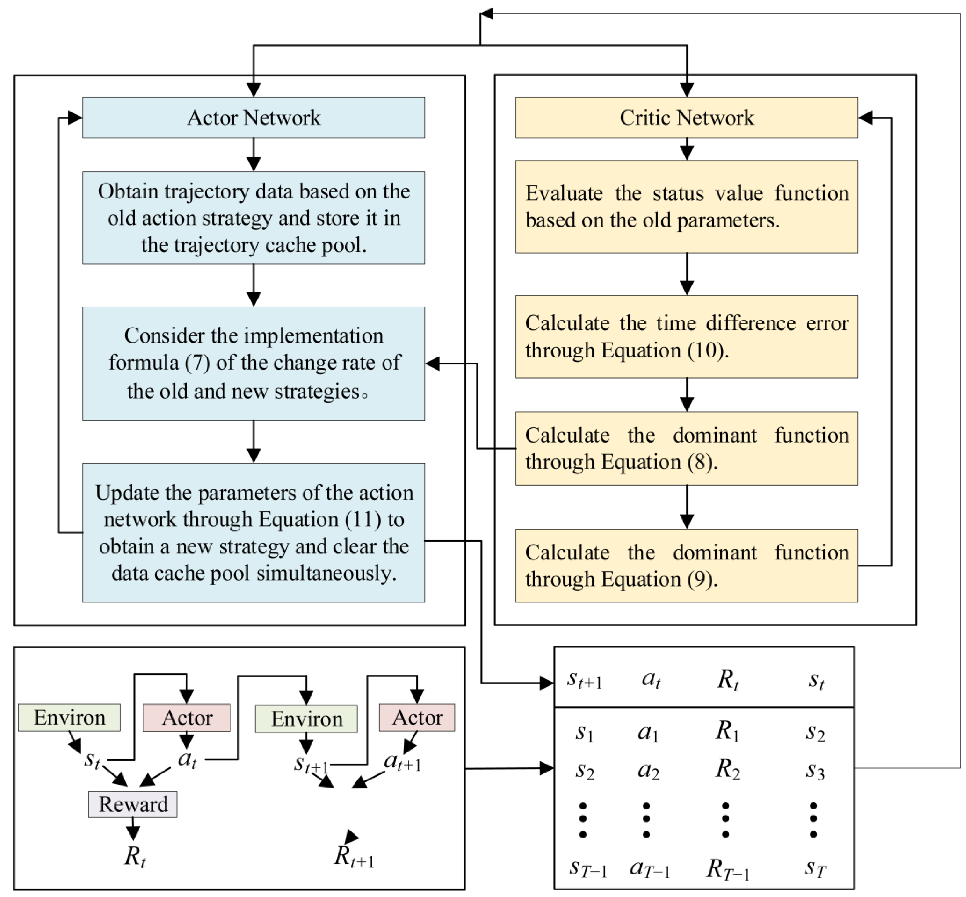
The action network of the PPO algorithm constantly interacts with the environment. By storing the interaction data into the trajectory cache pool, the last collected trajectory data can be released after completing a policy update. And after the new trajectory data is delivered to the actor network and the criterion network, the parameter updates of the actor network and the criterion network are performed, respectively. The updated network has more accurate value assessment and action selection performance. With the gradual deepening of the interaction between the intelligent body and the environment, the intelligent body training is gradually stabilized until convergence. The flowchart of the PPO algorithm is shown in Figure 2.

3.2. Parameter Identification of GFM-SVG Based on PPO Algorithm

In order to perform parameter identification, by transforming the GFM-SVG parameter identification problem into a reinforcement learning problem, a PPO-based GFM-SVG parameter identification process is proposed in this paper. The PPO algorithm can be used to solve the reinforcement learning problem.
The process of the PPO algorithm-based SVG parameter identification method is as follows. First, a simulation model of the GFM-SVG is built, which is used to obtain the dynamic response data of the system. Secondly, the operating environment of the PPO algorithm for the task of SVG parameter identification is constructed, which includes the state space, action space, and reward function of the intelligent body. Then, the actor network outputs the parameter tuning strategy. The critical network evaluates the state values. Through iterative loops, the actor network is optimized, which leads to the approximation of the real parameters of the GFM-SVG. Finally, when the parameter error is below a threshold, the training of the PPO algorithm is terminated, and the recognized values of the parameters of the network-forming SVG are obtained. The parameter identification process of GFM-SVG based on PPO is shown in Figure 3.
The state space S t is defined as the set of trajectories of reactive power output from the AC side of the identified GFM-SVG, which is denoted as follows:
S t = Q o t : t L + 1
where L is the sequence length of the trajectory.
The action space A t is denoted as follows:
A t = Δ k R P C t , Δ k p t , Δ k i t , Δ J t , Δ D p t , Δ G m t , Δ k q t , Δ R v t , Δ X v t , Δ n X / R t , Δ ω H P F t , Δ ω L P F R t , Δ ω L P F X t , Δ ω L P F Q t
where Δ k R P C t , Δ k p t , Δ k i t , Δ J t , Δ D p t , Δ G m t , Δ k q t , Δ R v t , Δ X v t , Δ n X / R t , Δ ω H P F t , Δ ω L P F R t , Δ ω L P F X t , Δ ω L P F Q t are the increment of the parameter to be identified at the moment of t time.
The reward function R t is defined as follows:
R t = Q o _ s i m t Q o _ r e a l t 2
where Q o _ s i m ( t ) is the reactive power output from the SVG identification model with typical parameters at the t time; and Q o _ r e a l t is the reactive power output from the simulation model with typical parameters at the t time.

4. Simulation Example

4.1. Key Parameters Selection Based on Trajectory Sensitivity Analysis

In order to verify the effectiveness of the proposed parameter identification method, the electromagnetic transient simulation model of the GFM-SVG is built on the CloudPSS platform [29]. Among them, the control link of the simulation model corresponds to Figure 1. In the simulation model, the typical parameters of the GFM-SVG are shown in Table 1.
In order to select the key parameters that have a large influence on the reactive power output of the GFM-SVG, it is necessary to calculate the trajectory sensitivity of each parameter in Table 1 to the reactive power. Among them, when calculating the trajectory sensitivity, the three-phase grounded short-circuit fault is set to occur from 4 s to 4.2 s at the PCC in the simulation model of the GFM-SVG. The average trajectory sensitivity is calculated from 3.9 s to 4.3 s. Based on the average trajectory sensitivity analysis method introduced in Section 2, the trajectory sensitivity of each parameter in GFM-SVG can be obtained as shown in Table 2. By comparing the values of trajectory sensitivity of each parameter, these eight parameters k p , J , k R P C , G m , k R , n X / R , k q , D p are finally selected as the dominant parameters of the network-type SVG as the key parameters to be recognized.

4.2. Validation of the Parameter Identification Results for GFM-SVGs

After determining the key identification parameters, in order to solve the parameter identification results, the PPO algorithm is used to identify the dominant parameters of the selected GFM-SVG. The identification results of the GFM-SVG are shown in Table 3. It can be observed that the identification error of each parameter of the GFM-SVG is low. The maximum error does not exceed 0.242%, which meets the accuracy requirements of parameter identification. In order to demonstrate the effectiveness of the proposed method, Table 3 also shows the identification results and errors obtained using the particle swarm optimization (PSO) algorithm. The identification error obtained using PSO is greater than that obtained using the method proposed in this paper. At the same time, the maximum error in parameter identification is 27.3%. The comparison shows that the parameter identification results obtained using the method proposed in this paper are closer to the typical values, which verifies the accuracy of the parameter identification results based on PPO.
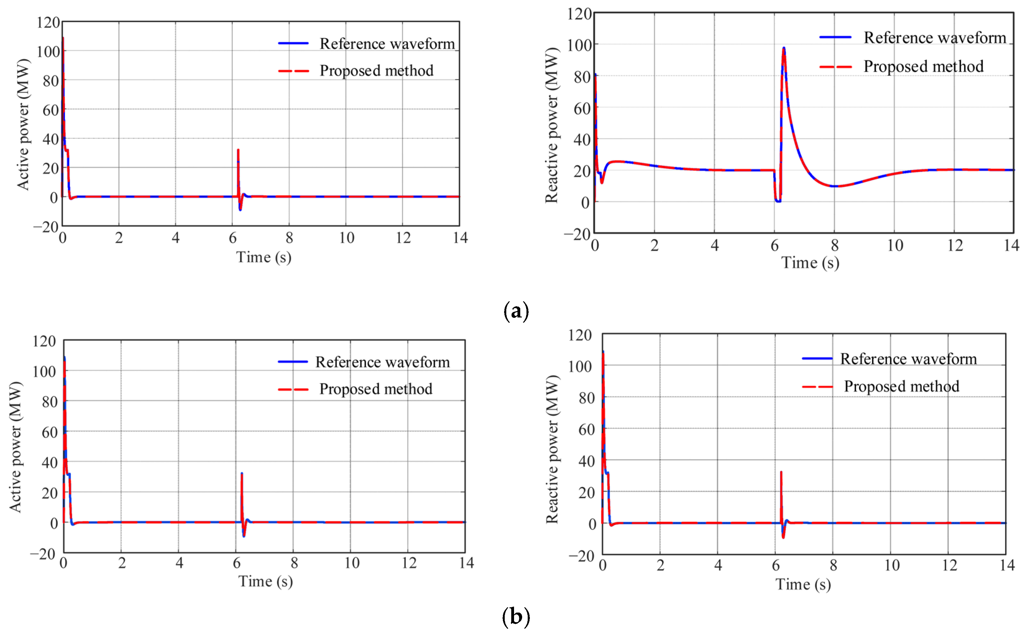
In order to verify the validity of the parameter identification results under different operating conditions, the simulation of the GFM-SVG is carried out in steady state and transient state by using the typical and identified parameters, respectively. Figure 4 shows the comparison of waveforms between the identified equivalent model and the simulation model under steady-state conditions. In Figure 4a, the reference reactive power is set to 20 MW, and in Figure 4b, the reference reactive power is set to 40 MW. It can be observed that under different reactive output reference values, the power waveforms of the GFM-SVGs with the proposed parameter identification method keep the same with the reference values, which verifies the accuracy of the results of the identification parameters.
In order to further validate the effectiveness of the proposed parameter identification method, simulations under faults are carried out in addition to the steady-state case. In the simulation, a three-phase grounded short circuit fault is set to occur at 6 s. Figure 5a shows the fluctuation of the reference reactive power of 20 MW and the ground fault resistance of 0.001 Ω. It can be observed that at this time, the power waveform of the GFM-SVG output with the proposed parameter identification method remains consistent with the reference value. If the fault severity is changed, when the ground fault resistance is set to 0.0005 Ω, the power waveform of the GFM-SVG output is shown in Figure 5b. The reference waveforms also remain consistent with the waveforms obtained using the parameter identification results, which further verify the accuracy of the parameter identification results.
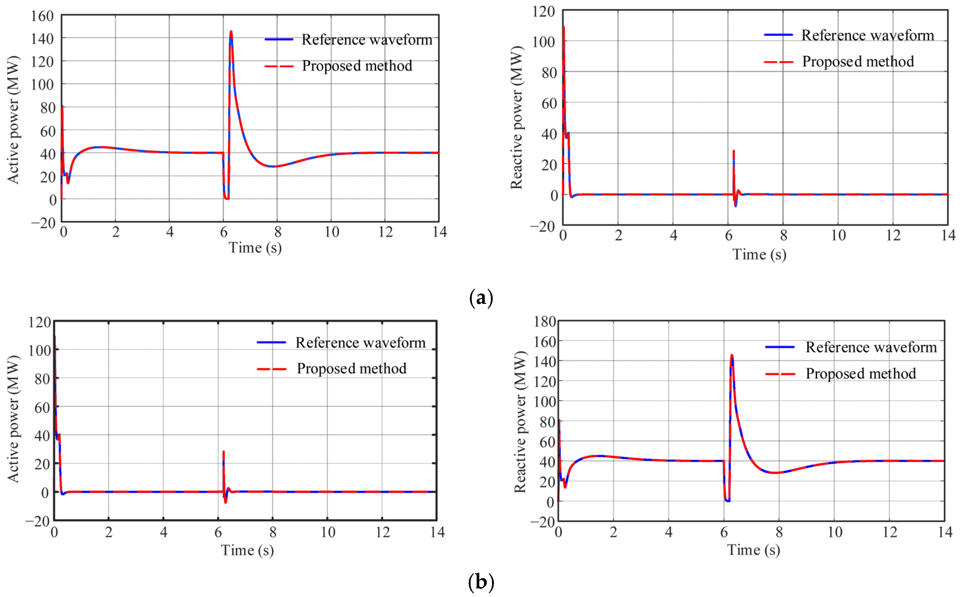
Finally, in order to validate the effectiveness of the parameter identification results under different reference setting values, Figure 6 shows the active and reactive power of GFM-SVGs with different fault severities when the reference value for reactive power is 40 MW. It can be observed that when the severity of the three-phase ground fault is changed, the output power of the GFM-SVG obtained using the proposed parameter identification method remains consistent with the reference waveform. The simulation results further validate that the proposed parameter identification method can accurately portray the output response characteristics of GFM-SVG under different operating conditions.

5. Conclusions

The GFM-SVG features the characteristics of high overload, fast response, and low delay, which is an important method to improve the receiving capacity of the regional grid in the load center. In order to accurately identify the key parameters of GFM-SVG, a parameter identification method of GFM-SVG based on trajectory sensitivity analysis and the PPO algorithm is proposed in this paper. Through the trajectory sensitivity analysis, the key dominant parameters influencing the power output of the GFM-SVG are selected as the parameters to be identified, which can reduce the dimension of parameter identification and improve the solving efficiency. Subsequently, the parameter identification framework and process of GFM-SVG based on the PPO algorithm are proposed. Simulation results show that the parameter identification method proposed in this paper can accurately solve the key parameters of the GFM-SVG. The proposed parameter identification method can accurately characterize the output response of the GFM-SVG under steady-state operation and transient disturbance conditions, which provides a solution for the parameter identification of the GFM-SVG in the scenarios of unknown parameters or parameter changes.

Author Contributions

Conceptualization, Y.T. and J.B.; methodology, Z.S. and T.C.; software, Y.T.; validation, P.S. and J.B.; formal analysis, Z.S. and Z.Z.; investigation, P.S. and Z.S.; resources, P.S. and X.W.; data curation, P.S.; writing—original draft preparation, T.C.; writing—review and editing, X.G. and Z.Z.; visualization, J.B. and X.W.; supervision, Y.T.; project administration, Y.T. and X.W.; funding acquisition, Y.T. and Z.Z. All authors have read and agreed to the published version of the manuscript.

Funding

This research was funded by the Science and Technology Project of State Grid Corporation of China “coordinated control technology and system R&D of multi-source heterogeneous reactive power compensation device containing grid-forming SVG” under grant 52199723003B.

Data Availability Statement

The data that support the research of this paper are available from the corresponding author upon reasonable request and with the permission of the State Grid Sichuan Electric Power Company.

Conflicts of Interest

The authors declare no conflicts of interest.

Abbreviations

The following abbreviations are used in this manuscript:
GFM-SVGGrid-forming static var generator
PPOProximal policy optimization
SVCStatic var compensator
RTDSReal-time digital simulation system
PSOParticle swarm optimization
DCDirect current
ACAlternating current

References

  1. Zhang, X.; Liu, J. Distributed Power, Energy Storage Planning, and Power Tracking Studies for Distribution Networks. Electronics 2025, 14, 2833. [Google Scholar] [CrossRef]
  2. Wang, Y.; Cao, T.; Gao, S.; Chen, Y.; Chen, W.; Zhou, X. Conceptualization and application prospect of digital twin system in hydroelectric unit. Proc. CSEE 2025, 45, 4526–4542. [Google Scholar]
  3. Wang, Y.; Wang, X.; Liao, J.; Su, M.; Liu, Y. Probabilistic small-signal stability assessment and cooperative control for interconnected microgrids via back-to-back converters. J. Mod. Power Syst. Clean Energy 2025, 13, 552–563. [Google Scholar] [CrossRef]
  4. Markovic, U.; Stanojev, O.; Aristidou, P.; Vrettos, E.; Callaway, D.; Hug, G. Understanding small-signal stability of low-inertia systems. IEEE Trans. Power Syst 2021, 36, 3997–4017. [Google Scholar] [CrossRef]
  5. Ratnam, K.S.; Palanisamy, K.; Yang, G. Future low-inertia power systems: Requirements, issues, and solutions—A review. Renew. Sustain. Energy Rev. 2020, 124, 109773. [Google Scholar] [CrossRef]
  6. Hosseinzadeh, N.; Aziz, A.; Mahmud, A.; Gargoom, A.; Rabbani, M. Voltage stability of power systems with renewable-energy inverter-based generators: A review. Electronics 2021, 10, 115. [Google Scholar] [CrossRef]
  7. Tuo, M.; Li, X. Security-constrained unit commitment considering locational frequency stability in low-inertia power grids. IEEE Trans. Power Syst. 2022, 38, 4134–4147. [Google Scholar] [CrossRef]
  8. Gomis-Bellmunt, O.; Tavakoli, S.D.; Lacerda, V.A.; Prieto-Araujo, E. Grid-forming loads: Can the loads be in charge of forming the grid in modern power systems? IEEE Trans. Smart Grid 2023, 14, 1042–1055. [Google Scholar] [CrossRef]
  9. Gao, H.; Huang, Z.; Diao, R.; Zhang, J.; Hou, B.; Wu, C.; Sun, F.; Lan, T. A machine learning-based SVG parameter identification framework using hardware-in-the-loop testbed. IEEE Trans. Power Syst. 2024, 39, 6849–6860. [Google Scholar] [CrossRef]
  10. Dahat, A.; Dhabale, A. Coordinated robust damping control for hybrid SVC/SSSC to enhance power system stability in large-scale systems. IEEE Trans. Ind. Appl. 2024, 60, 1589–1598. [Google Scholar] [CrossRef]
  11. Rosso, R.; Wang, X.; Liserre, M.; Lu, X.; Engelken, S. Grid-forming converters: Control approaches, grid-synchronization, and future trends—A review. IEEE Open J. Ind. Appl. 2021, 2, 93–109. [Google Scholar] [CrossRef]
  12. Blaabjerg, F.; Yang, Y.; Kim, K.A.; Rodriguez, J. Power electronics technology for large-scale renewable energy generation. Proc. IEEE 2023, 111, 335–355. [Google Scholar] [CrossRef]
  13. Sun, Y.; Wu, H.; Song, X.; Zhang, H.; Zhang, Y.; Chen, J.; Liu, H. Analysis of influence of grid-following and grid-forming static var generators on high-frequency resonance in doubly fed induction generator-based wind farms. Electronics 2024, 13, 3879. [Google Scholar] [CrossRef]
  14. Zhou, Z.; Mastoi, M.S.; Wang, D.; Haris, M. Control strategy of DFIG and SVG cooperating to regulate grid voltage of wind power integration point. Electr. Power Syst. Res. 2023, 214, 108862. [Google Scholar] [CrossRef]
  15. Li, X.; Zheng, Z.; Meng, J.; Wang, Q. Robust estimation of lithium battery state of charge with random missing current measurement data. Electronics 2024, 13, 4436. [Google Scholar] [CrossRef]
  16. Xia, T.; Ma, J.; Huang, H.; Peng, Y.; Xiao, X.; Chen, H.; Guo, R. Parameter identification of SVG controller based on RTDS hardware-in-loop test. Power Syst. Prot. Control 2020, 48, 110–116. [Google Scholar]
  17. Cao, B.; Yu, C.; Shuai, Y.; Xiaolin, Z.; Qi, W.; Liqiang, W.; Yongfei, Z. SVG model parameter test method based on controller hardware-in-loop. Low Volt. Appar. 2021, 6, 63. [Google Scholar]
  18. Guo, Q.; Sun, H.; Gao, L.; Xi, M.; Nie, Y.; Song, R. Research on intelligent identification method of SVG model parameters considering the random characteristics of wind farm. Proc. CSEE 2020, 40, 7950–7958. [Google Scholar]
  19. Zhai, B.; Ou, K.; Wang, Y.; Cao, T.; Dai, H.; Zheng, Z. Parameter identification of PMSG-based wind turbine based on sensitivity analysis and improved gray wolf optimization. Energies 2024, 17, 4361. [Google Scholar] [CrossRef]
  20. Wu, H.; Wang, X. Small-signal modeling and controller parameters tuning of grid-forming VSCs with adaptive virtual impedance-based current limitation. IEEE Trans. Power Electron. 2021, 37, 7185–7199. [Google Scholar] [CrossRef]
  21. Li, D.; Wang, T.; Pan, W.; Ding, X.; Gong, J. A comprehensive review of improving power quality using active power filters. Electr. Power Syst. Res. 2021, 199, 107389. [Google Scholar] [CrossRef]
  22. Wang, Y.; Lu, C.; Zhu, L.; Zhang, G.; Li, X.; Chen, Y. Comprehensive modeling and parameter identification of wind farms based on wide-area measurement systems. J. Mod. Power Syst. Clean Energy 2016, 4, 383–393. [Google Scholar] [CrossRef]
  23. Gu, Y.; Cheng, Y.; Chen, C.L.P.; Wang, X. Proximal policy optimization with policy feedback. IEEE Trans. Syst. Man Cybern. Syst. 2021, 52, 4600–4610. [Google Scholar] [CrossRef]
  24. An, H.; Wang, L. Robust topology generation of Internet of Things based on PPO algorithm using discrete action space. IEEE Trans. Ind. Inform. 2023, 20, 5406–5414. [Google Scholar] [CrossRef]
  25. Liu, X.; Zhang, P.; Xie, H.; Lu, X.; Wu, X.; Liu, Z. Graph attention network based deep reinforcement learning for voltage/var control of topologically variable power system. J. Mod. Power Syst. Clean Energy 2024, 13, 215–227. [Google Scholar] [CrossRef]
  26. Wu, P.; Chen, C.; Lai, D.; Zhong, J.; Bie, Z. Real-time optimal power flow method via safe deep reinforcement learning based on primal-dual and prior knowledge guidance. IEEE Trans. Power Syst. 2024, 40, 597–611. [Google Scholar] [CrossRef]
  27. Kamruzzaman, M.; Duan, J.; Shi, D.; Benidris, M. A deep reinforcement learning-based multi-agent framework to enhance power system resilience using shunt resources. IEEE Trans. Power Syst. 2021, 36, 5525–5536. [Google Scholar] [CrossRef]
  28. Jin, J.; Xu, Y. Optimal policy characterization enhanced actor-critic approach for electric vehicle charging scheduling in a power distribution network. IEEE Trans. Smart Grid 2020, 12, 1416–1428. [Google Scholar] [CrossRef]
  29. Song, Y.; Chen, Y.; Yu, Z.; Huang, S.; Shen, C. CloudPSS: A high-performance power system simulator based on cloud computing. Energy Rep. 2020, 6, 1611–1618. [Google Scholar] [CrossRef]
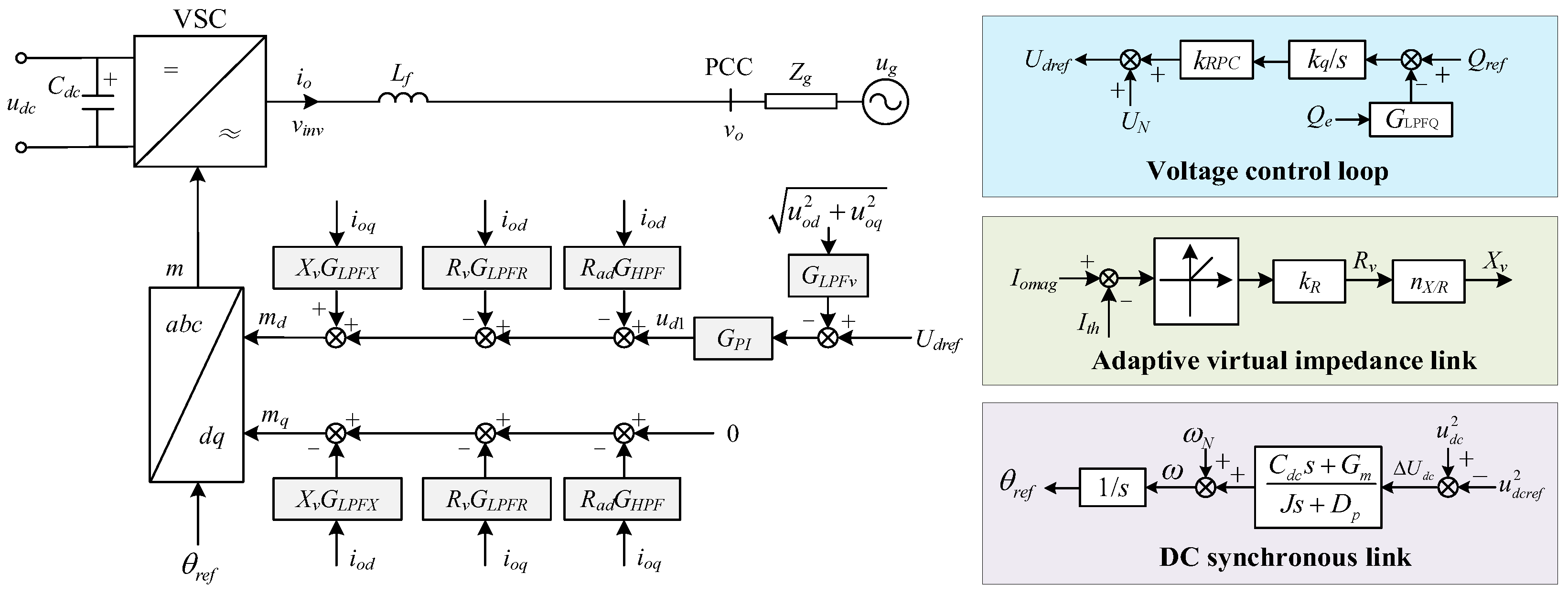
Figure 1. Control block diagram of GFM-SVG based on the virtual impedance.
Electronics 14 03119 g001
Figure 2. Flowchart of the PPO algorithm.
Electronics 14 03119 g002
Figure 3. The parameter identification process of GFM-SVG based on PPO.
Electronics 14 03119 g003
Figure 4. Active and reactive power of GFM-SVG with different reactive power reference values: (a) Qref = 20 MW; (b) Qref = 40 MW.
Electronics 14 03119 g004
Figure 5. Active and reactive power of GFM-SVGs with different fault severity when the reference value for reactive power is 20 MW: (a) Qref = 20 MW, Rf = 0.001 Ω; (b) Qref = 20 MW, Rf = 0.0005 Ω.
Electronics 14 03119 g005
Figure 6. Active and reactive power of GFM-SVGs with different fault severity when the reference value for reactive power is 40 MW: (a) Qref = 40 MW, Rf = 0.001 Ω; (b) Qref = 40 MW, Rf = 0.0005 Ω.
Electronics 14 03119 g006
Table 1. The typical parameters of the GFM-SVG.
VariableParameterVariableParameter
kp5 ω L P F R 100π
ki0.2kR10
ω H P F 20πnx/r5
ω L P F X 100πkq0.2
J0.0254648 ω L P F Q 100π
kRPC0.1Dp59.685
Gm0.5 ω L P F v 20π
Table 2. The trajectory sensitivity of each parameter in GFM-SVG.
VariableParameterVariableParameter
kp47.079 ω L P F R 1.761
ki7.714kR79.495
ω H P F 0.257nx/r193.949
ω L P F X 0.593kq192.855
J80.811 ω L P F Q 1.665
kRPC488.197Dp25.838
Gm3121.849 ω L P F v 3.063
Table 3. The identification results of the GFM-SVG.
VariableTypical ValuePPO (Error)PSO (Error)
kp55.0094 (0.188%)5.7826 (15.652%)
J0.02546480.0255 (0.138%)0.0280 (9.957%)
kRPC0.10.0998 (0.200%)0.1273 (27.300%)
Gm0.50.5012 (0.240%)0.5170 (3.400%)
kR1010.0079 (0.079%)9.4101 (5.899%)
nx/r54.9879 (0.242%)5.1343 (2.686%)
kq0.20.1997 (0.150%)0.1598 (20.100%)
Dp59.68559.7018 (0.028%)70.0462 (17.355%)
Disclaimer/Publisher’s Note: The statements, opinions and data contained in all publications are solely those of the individual author(s) and contributor(s) and not of MDPI and/or the editor(s). MDPI and/or the editor(s) disclaim responsibility for any injury to people or property resulting from any ideas, methods, instructions or products referred to in the content.