Article

UDirEar: Heading Direction Tracking with Commercial UWB Earbud by Interaural Distance Calibration

1
Department of Computer Science and Engineering, Pohang University of Science and Technology, Pohang 37673, Republic of Korea
2
Graduate School of Artificial Intelligence, Pohang University of Science and Technology, Pohang 37673, Republic of Korea
*
Author to whom correspondence should be addressed.
Electronics 2025, 14(15), 2940; https://doi.org/10.3390/electronics14152940
Submission received: 22 June 2025 / Revised: 18 July 2025 / Accepted: 22 July 2025 / Published: 23 July 2025
(This article belongs to the Special Issue Wireless Sensor Network: Latest Advances and Prospects)

Abstract

Accurate heading direction tracking is essential for immersive VR/AR, spatial audio rendering, and robotic navigation. Existing IMU-based methods suffer from drift and vibration artifacts, vision-based approaches require LoS and raise privacy concerns, and RF techniques often need dedicated infrastructure. We propose UDirEar, a COTS UWB device-based system that estimates user heading using solely high-level UWB information like distance and unit direction. By initializing an EKF with each user’s constant interaural distance, UDirEar compensates for the earbuds’ roto-translational motion without additional sensors. We evaluate UDirEar on a step-motor-driven dummy head against an IMU-only baseline (MAE 30.8°), examining robustness across dummy head–initiator distances, elapsed time, EKF calibration conditions, and NLoS scenarios. UDirEar achieves a mean absolute error of 3.84° and maintains stable performance under all tested conditions.

1. Introduction

Tracking the orientation of mobile devices has become a fundamental component in a wide range of applications. In immersive environments such as virtual reality (VR) and augmented reality (AR), accurate pose estimation of head-worn or handheld devices directly influences user experience and system interaction fidelity [1,2,3,4,5]. Similarly, in robotics [6,7,8], understanding not only the position but also the viewing direction of agents is essential for tasks such as navigation, human–robot interaction, and collaborative perception. Furthermore, in domains like 3D reconstruction [9,10,11,12], camera orientation is a key parameter in recovering scene geometry and structure.
Understanding where a person is looking is especially important in VR/AR applications, where it determines the user’s field of view and drives scene rendering. Accurate tracking enhances immersion and prevents motion sickness [13,14]. It also enables intuitive interactions, such as gaze-based selection, and facilitates communication in multi-user settings by revealing users’ attention and intent. Overall, head direction plays a key role in interaction, navigation, and spatial awareness in immersive environments.
Several techniques have been explored for heading direction tracking. Inertial measurement units (IMUs) offer a low-cost, lightweight solution and are commonly embedded in head-mounted displays or mobile devices. However, IMUs suffer from drift and cumulative error without external references [15,16,17,18,19,20,21,22]. Vision-based approaches [23,24,25,26,27], often relying on facial landmark tracking or depth estimation, provide high accuracy but require line of sight (LoS) and suffer in low-light or occluded environments. Acoustic-based methods [15,16,17,28,29,30,31,32], though less common, have been proposed to estimate orientation using time of arrival or phase differences, but they are generally sensitive to environmental noise and multipath. In recent years, wireless signal-based methods have gained attention for their potential to operate passively and robustly across different environments. Wi-Fi [27,33,34] and RFID tags [35,36] have demonstrated feasibility for tracking heading direction and pose estimation. However, they often rely on infrastructure deployment or require controlled settings and are generally more susceptible to multipath interference due to their narrower bandwidth.
Among various wireless technologies, ultra-wideband (UWB) radio has emerged as a strong candidate due to its high temporal resolution, robustness to multipath, and increasing integration into commercial off-the-shelf (COTS) devices. UWB radio chips are now being incorporated into modern smartphones [37,38,39,40] and are expected to appear soon in wireless earbuds [41] for applications such as spatial audio and device localization. This trend presents an opportunity to explore heading direction tracking using only COTS UWB-equipped devices, specifically, a smartphone and a pair of wireless earbuds, without the need for any additional hardware or sensors. In this work, we explore this opportunity, but doing so presents several challenges due to the limitations of commercially available UWB devices and the characteristics of head-mounted wireless devices.
Challenge 1: Limited access to low-level UWB data in COTS devices. Traditional UWB-based localization and orientation estimation methods rely on low-level signal features such as amplitude, phase difference, or the full channel impulse response (CIR), which provide fine-grained spatial information [42,43,44,45,46,47]. These features enable precise angle-of-arrival (AoA) estimation using antenna arrays or multiple paths. However, COTS UWB devices abstract away these raw signals and instead expose only processed, high-level data, typically limited to distance and direction measurements. This necessitates alternative approaches that can infer head direction from sparse or aggregated measurements.
Challenge 2: Constraints of wireless earbuds. Wireless earbuds are designed with strict power and form-factor constraints. Unlike VR headsets or smartphones, which can incorporate multiple sensors and perform on-device computation, earbuds must maintain low power consumption to support long battery life and user comfort. This limits the feasibility of using additional sensing modalities such as inertial sensors or microphones. Moreover, wireless earbuds often operate as passive devices, responding to commands from a paired device with minimal independent processing. Therefore, any head tracking system must operate with minimal reliance on local computation. This presents a significant design constraint in balancing accuracy with hardware limitations.
Challenge 3: Roto-translational motion (roto-translational motion means motion contains both rotation and translation motion) of earbuds. Unlike fixed sensors rigidly attached to a central point on the head, earbuds are located on either side of the head and experience non-rigid motion during head rotation. When a person turns their head, each earbud undergoes both rotational and translational movement, tracing an arc-like path. This introduces spatial disparity between the devices and causes the UWB-measured positions to reflect not only orientation but also the geometric offset of each earbud. As a result, simple geometric models assuming rigid head rotation do not hold.
To address these challenges, we propose UDirEar, a novel heading direction tracking system that is friendly to wireless earbuds and their paired device. To minimize wireless earbud power consumption, UDirEar relies exclusively on UWB measurements and excludes all other sensing modalities. It applies an extended Kalman filter (EKF) to fuse UWB sensor data and correct measurement errors. Since no additional sensors are used, the EKF model itself handles calibration based on the interaural distance (distance between the left and right ear). This distance remains constant for each individual and is set once during the EKF initialization stage. In this paper, we describe how UDirEar exploits the characteristics of UWB wireless earbuds to correct errors caused by roto-translational motion. To correct errors from translational motion, UDirEar fuses sensor values with an EKF and corrects tracking errors with EKF calibration that anchors on the interaural distance. We compare UDirEar’s performance against the IMU-based baseline MUSE, examining its variation across factors such as dummy head–initiator distance, elapsed time, EKF calibration, and non-line-of-sight (NLoS) conditions. Experimental results confirm that UDirEar achieves a mean absolute error (MAE) of 3.84°. Our main contributions are as follows.
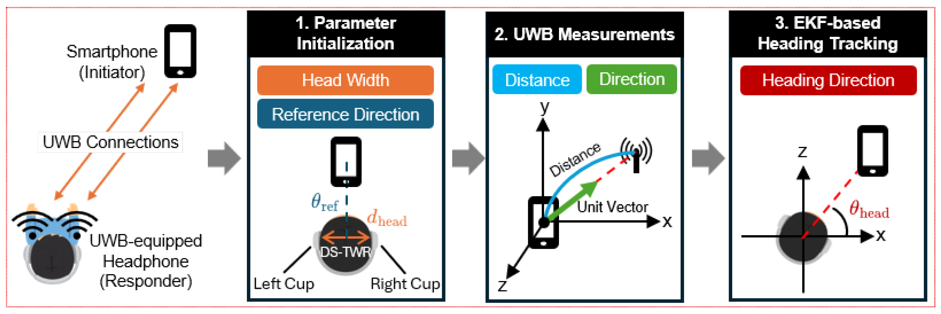
  • We propose UDirEar, a heading direction tracking system that relies solely on UWB sensors embedded in wireless earbuds. Because it uses a COTS UWB device, it operates only on high-level UWB information such as distance and direction without access to the amplitude or phase of the CIR.
  • We present an EKF model that exploits the interaural distance for heading direction tracking with both ears. Rather than estimating heading directly from sensor distance and direction, this model infers heading indirectly through sensor placement. By inserting an EKF model between raw measurements and final tracking, UDirEar reduces performance degradation due to sensor error and defines the EKF model explicitly around the constant interaural distance.
  • We experimentally evaluate UDirEar’s performance against existing methods. We further analyze how factors such as target distance, elapsed time, EKF calibration, and NLoS conditions impact accuracy. We compare results across different scenarios and explain the reasons behind any observed performance changes.
The remainder of this paper is organized as follows. Section 2 reviews prior work on heading direction tracking, and Section 3 provides background on UWB technology and the extended Kalman filter. In Section 4, we describe the overall system architecture, which is then evaluated in Section 5. Section 6 outlines directions for future work, and Section 7 concludes this paper.

2. Related Work

Head orientation tracking techniques can be broadly categorized into vision-based, acoustic-based, IMU-based, and wireless signal-based methods. Each modality presents unique advantages and limitations concerning accuracy, privacy, LoS constraints, and the availability of COTS hardware.
Vision-based methods [20,23,24,25,26] typically use cameras to detect facial landmarks and infer angle of head. Such systems achieve high accuracy and are often used as ground truth for evaluating other methods. For example, Kumar et al. [20] demonstrated that visual SLAM (Simultaneous Localization and Mapping) provided significantly lower orientation errors (4.5°) compared to IMU-only methods (9.6°) outdoors. However, vision-based solutions inherently require consistent lighting conditions and an LoS to the target, limiting their robustness in dynamic environments. Moreover, reliance on camera systems raises substantial privacy concerns due to the sensitive visual data captured.
Acoustic tracking systems use inaudible sound signals, typically ultrasound, to determine orientation by analyzing sound propagation from sound source to target. Acoustic methods [15,16,17,28,29,30,31,32,48] inherently provide enhanced privacy compared to vision-based systems, as they do not capture visual or sensitive data. These approaches also demonstrate moderate resilience against LoS constraints due to the reflective and diffractive properties of sound waves. Recent advancements have shown acoustic-based tracking’s potential accuracy and usability. For instance, FaceOri [30] utilized smartphone-generated ultrasonic signals and wireless earbuds’ microphones to achieve low orientation errors (3.7 ° yaw, 5.8 ° pitch), highlighting acoustic tracking’s practicality with widely available devices. Similarly, HeadTrack [32] employed FMCW chirps transmitted from smartphones to earbuds, reporting orientation errors (4.9 ° yaw, 6.3 ° pitch). Further, EHTrack [31] demonstrated a 1.83 ° mean orientation error using structured acoustic signals between speakers and earbuds. Despite these advantages, acoustic methods remain susceptible to ambient noise interference and have a limited operational range, typically effective only within a few meters.
IMU-based tracking leverages sensors such as gyroscopes, accelerometers, and magnetometers to estimate orientation independently from external references. Ferlini et al. [21,22] demonstrated the potential for earbud-integrated IMUs to provide sub-degree accuracy for brief head movements, highlighting their instantaneous precision. However, IMU methods typically suffer from drift accumulation due to gyroscope bias integration, resulting in deteriorating accuracy over time. Zhao et al. [26] tackled this by employing dual IMUs (one fixed in the vehicle, one on the user’s head) to remove external motion interference, effectively reducing drift-related errors in dynamic driving environments. Nevertheless, without continuous external recalibration or sensor fusion, IMU-only systems are inherently limited in their ability to sustain accurate orientation tracking over prolonged durations.
Wireless signal-based approaches, leveraging Wi-Fi [27,33,34], RFID [35,36], or UWB signals [42,43,44,45,46,47,49,50,51], estimate orientation by analyzing signal propagation characteristics such as signal strength, phase shifts, or AoA. These methods inherently provide improved privacy compared to vision-based systems since wireless signals alone offer limited personally identifiable information. Moreover, RF signals are robust to many NLoS environments, supporting reliable operation with high penetration even when direct visibility is compromised. These methods increasingly leverage widely available consumer electronics, making them highly practical.
UWB-based tracking methods, in particular, have recently attracted attention for orientation estimation due to their high time resolution and multipath resilience. Zhou et al. [50] fused high-level UWB information with smartphone gyroscope information, achieving significant error reduction (gyro-only 7.6 ° , fused 2.7 ° ). Furthermore, Xie et al. [27] presented a Wi-Fi-based head tracking approach using channel state information (CSI), achieving an average yaw error below 4 ° in real-time applications such as driver monitoring. Additionally, UHead [49] demonstrated UWB radar’s capability to measure head orientation non-intrusively, achieving a 13 ° median orientation error for driver attention monitoring, underscoring UWB-based systems’ usability and installation simplicity. Nonetheless, wireless signal-based tracking often relies on fixed infrastructure or multiple synchronized devices, potentially limiting immediate portability.
To overcome individual modality limitations, recent hybrid approaches have combined complementary sensors or employed specialized calibration techniques. FaceOri [30] integrated acoustic signals with earphone IMUs, while Zhao et al. [26] utilized dual IMUs for dynamic calibration. Ferlini et al. [21] proposed automatic calibration for magnetometers within earbuds to mitigate magnetic interference, demonstrating significant accuracy improvements (3 ° errors) without user intervention. Such hybrid and calibration methods illustrate that exploiting known constraints or combining sensor modalities can significantly enhance tracking robustness and accuracy.
Building upon these insights, we introduce UDirEar, a heading direction tracking system that relies solely on UWB sensors embedded in wireless earbuds and uses a smartphone as the anchor, operating only on high-level information of distance and direction without access to CIR amplitude or phase. We present an EKF model that enforces a constant interaural distance constraint to infer heading direction indirectly from dual-ear UWB readings, reducing errors caused by sensor noise from roto-transitional motion. We experimentally evaluate UDirEar against existing methods, analyzing how factors such as target distance, elapsed time, and NLOS conditions impact accuracy and robustness.

3. Technical Background

3.1. UWB Primer

UWB is a wireless communication technology that operates over a very wide frequency range, typically more than 500 MHz or 20% of the carrier frequency. Among various implementation schemes, impulse radio UWB (IR-UWB) is the most commonly used. It transmits data using very short pulses, enabling both wireless communication and precise time-of-flight (ToF) measurement. Commercial UWB systems operate in the 3.1 to 10.6 GHz frequency band with low transmission power (typically limited to −41.3 dBm/MHz), and the spectrum is divided into multiple 499.2 MHz wide channels, as defined by standards such as IEEE 802.15.4 [52].
UWB enables accurate ranging by measuring the ToF of the first arriving signal path, typically the LoS path. When a UWB pulse is transmitted, it travels through various paths due to reflections, and the initiator detects the earliest arriving pulse using the CIR. The preamble of a UWB packet is designed to have strong autocorrelation properties, allowing precise timestamping of the first path arrival.
This high level of precision has led to the adoption of UWB in consumer devices, including smartphones such as the iPhone [37,38,39] and Samsung Galaxy series [40]. In addition to smartphones, UWB technology is now integrated into a growing range of consumer electronics, such as smartwatches [53,54], and is expected to be incorporated soon into wireless earbuds [41]. These devices provide processed spatial data, such as distance and angle, through built-in UWB modules and developer-friendly APIs [55,56].

3.2. UWB Positioning Using Ranging and AoA

UWB systems enable high-precision positioning by combining ToF-based ranging with AoA estimation. When a UWB initiator is equipped with an antenna array, it can estimate both the distance and direction to a transmitting device, allowing accurate positioning using only a single initiator.

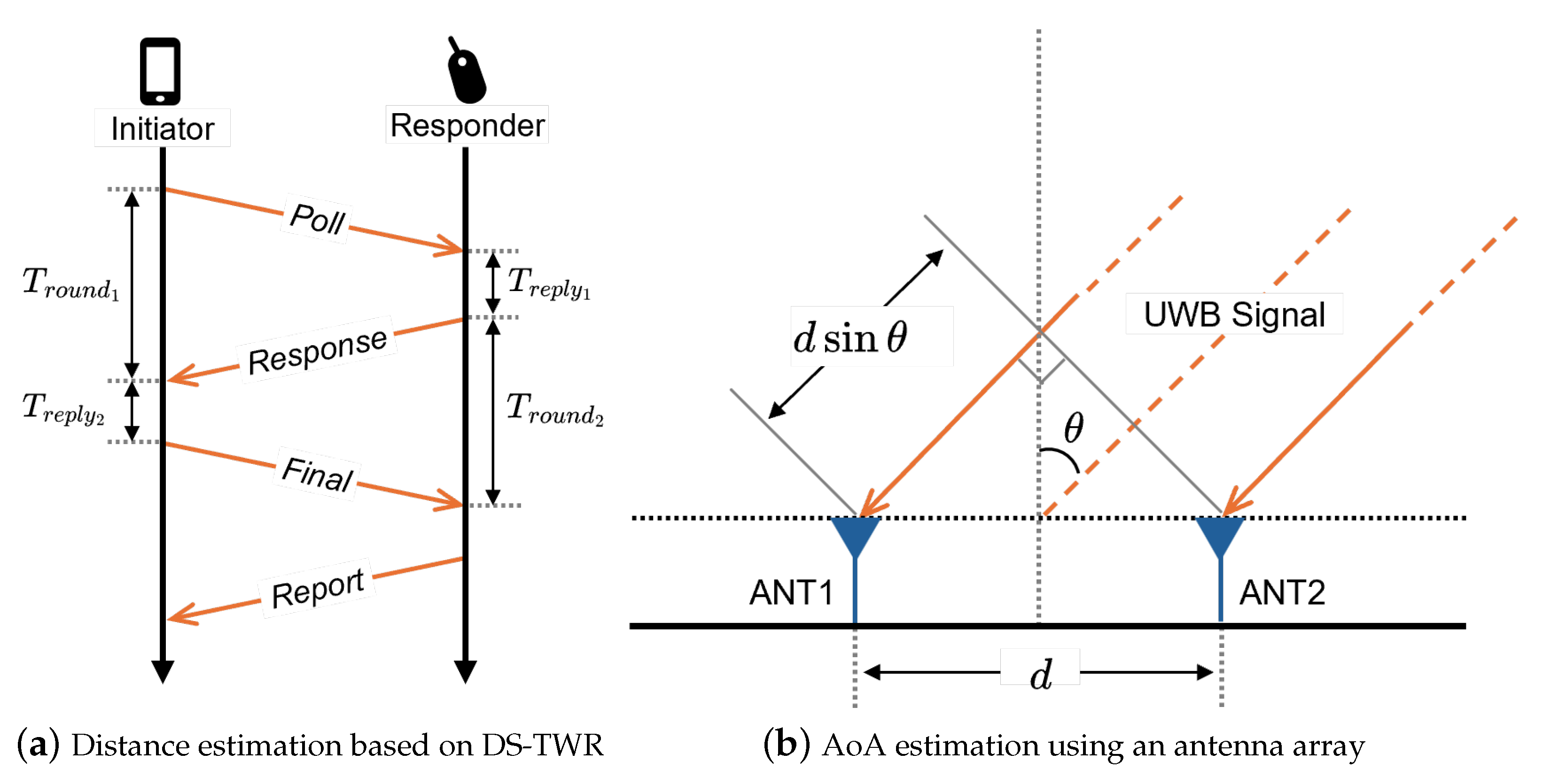
3.2.1. ToF-Based Ranging

The IEEE 802.15.4 standard [52] defines two primary methods for UWB-based ranging: single-sided two-way ranging (SS-TWR) and double-sided two-way ranging (DS-TWR) [57]. In SS-TWR, the initiator estimates the ToF by measuring the round-trip time and subtracting the known processing delay of the responder. While simple, this approach is sensitive to clock offset between devices, which may lead to inaccurate distance estimation. To address this issue, DS-TWR introduces an additional message exchange that enables both the initiator and responder to measure delays independently. By combining timing information from both ends, DS-TWR effectively compensates for clock discrepancies and improves ranging accuracy.
As illustrated in Figure 1a, the DS-TWR procedure consists of three primary message exchanges, Poll, Response, and Final, followed optionally by a Report message. The initiator sends a Poll message, the responder replies with a Response, and the initiator completes the exchange by transmitting a Final message. Each device records local transmission and reception timestamps, which are used to estimate the ToF while mitigating clock offset and drift. The ToF T f is calculated as follows:
T f = T r o u n d 1 · T r o u n d 2 T r e p l y 1 · T r e p l y 2 T r o u n d 1 + T r o u n d 2 + T r e p l y 1 + T r e p l y 2
The estimated distance is then calculated by multiplying the ToF by c · T f , where c denotes the speed of light and T f accounts for the temporal resolution of the system. A Report message may be used to convey the computed result back to the initiator.

3.2.2. AoA Estimation

AoA estimation allows an initiator to infer the direction of the incoming signal, which can be leveraged for localization or beamforming. One widely used method is phase difference of arrival (PDoA), which estimates AoA by analyzing the phase differences of the received signal across a known antenna array geometry. As illustrated in Figure 1b, consider a uniform linear array with antenna spacing d. The AoA θ can be estimated from the PDoA Δ ϕ between adjacent antennas, which is related to θ as follows:
θ = arcsin λ · Δ ϕ 2 π d ,
where f c is the carrier frequency and λ = c / f c is the signal wavelength. In practice, multipath effects and phase ambiguity (due to phase wrapping) can degrade performance, which may be mitigated through array calibration, spatial filtering, or combining with other techniques such as ToF or amplitude-based methods.

3.2.3. Three-Dimensional Positioning Capabilities of COTS UWB Devices

COTS UWB devices, such as those in recent smartphones, perform ranging and AoA estimation using built-in algorithms and L-shaped antenna arrays. Unlike linear arrays, which can measure only a single direction, L-shaped antenna arrays allow simultaneous estimation of azimuth and elevation, which enables accurate 3D localization. While some compact devices may only support range due to size constraints, angle information is reciprocal, meaning that 3D positioning can still be achieved if only one side provides angular estimates. By combining range and directional cues, such systems can support active sensing applications such as motion tracking and spatial interaction.

3.3. Error Correction Using Extended Kalman Filter

Sensor-based systems predict the state of a target by feeding measurement values obtained from sensors into a pre-designed model. However, sensor values have inevitable noise and bias, and the model itself cannot perfectly emulate real-world dynamics. As a result, discrepancies arise between the model’s predictions and the ground truth. To mitigate these discrepancies, we employ the EKF. The EKF fuses the model’s predicted state and the sensor values by computing a weighted sum based on Kalman gain. By simultaneously accounting for both process noise and measurement noise, the EKF effectively compensates for uncertainties in the sensor value and the model, yielding significantly improved state estimation [58,59,60].
The Kalman filter (KF) is a recursive state estimation algorithm that fuses a process model, known control inputs, and noisy measurements to produce an estimate of the system’s state [61]. Uncertainty arises from both the process model and the measurements. To compensate for these uncertainties, the KF recursively fuses the process model’s prediction and the measurements using a Kalman gain that reflects their respective covariances. At each iteration, the filter consists of a prediction step and an update step, as defined in Equations (3)–(8) (Table 1 summarizes the descriptions of symbols used in Equations (3)–(8)).
x ^ k = A x ^ k 1 + B u k 1 + w k
P k = A P k 1 A + Q k
S k = H P k H + R k
K k = P k H k S k 1
x ^ k = x ^ k + K k z k H x ^ k
P k = I K k H P k
The prediction step (Equations (3) and (4)) uses the process model to estimate the state and its uncertainty at the current time step. The update step (Equations (5)–(8)) incorporates the actual sensor measurement to correct the prediction using the Kalman gain.
While the KF is an effective method for reducing errors in both the process model and sensor values, it is fundamentally constrained by its requirement that the process model be linear, as implied by the first equation. In contrast, real-world dynamics are typically nonlinear. To address this limitation, the EKF extends the KF to handle nonlinear process models. Its principal idea and the key difference from the standard KF is the linearization of the nonlinear state transition and observation functions via a first-order Taylor series expansion [62,63]. Apart from this local linearization step, the EKF follows the same prediction–update cycle as the KF.

4. Methods

In this section, we will present the detailed design for estimating the heading direction using both ears, as well as the EKF design to compensate for precision degradation caused by the ears’ roto-translational motion.

4.1. Heading Direction Basic Model

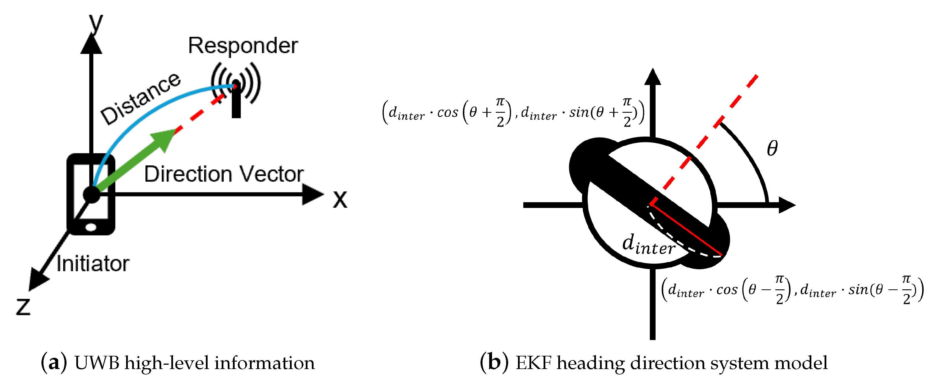
4.1.1. UWB Coordination System

When using UWB through a COTS device, we cannot obtain the CIR amplitude and phase information as we would with a dedicated UWB device. Consequently, we must rely on high-level UWB information provided by the UWB API [55,56]. Figure 2a illustrates the information obtainable via the API, which returns the distance between the initiator and the responder, as well as a unit direction vector. Therefore, if we denote the API output as the distance d and the unit direction vector ( θ x , θ y , θ z ), we can express the responder device’s position in a three-dimensional Cartesian coordinate with the initiator located at the origin.
( x , y , z ) = ( d · θ x , d · θ y , d · θ z )
From the above equation, when a signal arrives at the initiator at time t, we can determine the relative position between the initiator and the responder in a three-dimensional Cartesian coordinate.

4.1.2. Heading Direction Model

Once the relative positions between the initiator and each responder have been determined, mounting the responder units on both ears yields the 3D coordinates of the left and right ear. Denote the left-ear position by ( x l , y l , z l ) and the right-ear position by ( x r , y r , z r ). The 3D vector from the left ear to the right ear, which serves as our heading direction proxy, is then given by
v 3 D = ( x r x l , y r y l , z r z l )
In 3D orientation, we decompose motion into yaw (heading), pitch, and roll. As shown in Figure 2b, since the y-coordinate encodes only pitch/roll effects, we project v 3 D onto the xz-plane to eliminate these and estimate pure yaw, and with this projected vector, we calculate slope of line m e a r s that passes both ears.
v 2 D = ( x r x l , z r z l )
m e a r s = z r z l x r x l
Because the heading direction must be perpendicular to the line connecting both ears in the xz-plane, we can finally compute the heading direction θ as follows:
θ = arctan 1 m e a r s = arctan Δ x Δ z
As shown, if the relative positions between both ears and the COTS UWB device are known, we can determine the heading direction. However, this approach relies on knowing the precise positions of both ears and, in contrast to directional information, the limited accuracy of distance measurements precludes fine-grained estimation [64]. Moreover, since inference arises because both ears are located at the sides of the head, errors from these measurement challenges must be corrected to achieve fine-grained heading direction tracking.

4.2. EKF-Based Correction of Roto-Translational Interference

To estimate heading direction from ear positions, it is essential to know the precise locations of both ears. However, even if the head’s primary motion is a pure rotation about the neck axis, the ears do not undergo pure rotation alone. Since the ears are attached to both sides of the head, they not only undergo rotational motion about the head’s central axis but also perform a translation that traces a circular arc around that same axis, meaning they execute a roto-translational motion. Unfortunately, when a responder device undergoes translation, the direction estimates provided by the API suffer in accuracy [50]. Moreover, since APIs do not expose low-level CIR amplitude or phase data, it is impossible to determine whether the reported values have already been degraded by translational motion or to correct for that degradation based solely on high-level outputs. Using Equation (9), we estimate ear positions from the distance and direction measurements provided by the UWB API. However, as noted above, both measurements suffer significant accuracy degradation under combined translational and rotational motion. Moreover, the UWB API does not expose low-level CIR phase and amplitude data, making direct error compensation impossible. Therefore, in this study we introduce a dedicated calibration technique to overcome these limitations.
To address this issue, UDirEar leverages a correction method that uses an EKF. The EKF integrates the process model with sensor measurements to minimize both the model’s estimation error and the sensor’s measurement error. Since the primary source of error in the current heading direction estimate is the roto-translational motion of both ears, we aim to apply process model-based estimation to reduce the sensor measurement error. In constructing our system model, we leverage the interaural distance, which means the distance between the two ears. Figure 2b shows the process model used in the EKF for heading direction estimation. By initializing the model with the constant interaural distance, which is unique to each user, we can use the same value throughout a single session. In the next section, we will describe in detail how we designed the EKF to correct the UWB measurements.

4.3. System Overview

Figure 3 provides an overview of UDirEar, an EKF that leverages interaural distance to fuse UWB measurements. The system consists of three main stages: 1. Parameter Initialization, in which the process model is initialized; 2. UWB Measurements, which acquire relative position information for both ears; and 3. EKF-based Heading Tracking, which fuses the previously defined model with UWB sensor values in an EKF to obtain an accurate heading direction despite the ears’ roto-translational motion.
In the Parameter Initialization stage, the user briefly holds the head still to measure the interaural distance, the UWB initiator’s relative position from the head, and the initial heading direction state. To determine the interaural distance, we use the UWB API to measure the distance and direction from the initiator to each responder attached to the left and right earbuds. The interaural distance is then computed from the earbud position coordinates obtained via Equation (9). After initialization, in the UWB Measurements stage, the initiator gathers distance and direction values from the responder at both ears. The EKF-based Heading Tracking stage then uses the initialized values as correction metrics for UWB measurement errors. We operate UDirEar’s EKF on an initiator (smartphone) to maintain the energy efficiency of responder (earbud) since the EKF is a computaionally intensive algorithm. Collectively, these stages calibrate the system geometry, acquire real-time UWB data, and apply EKF-based corrections to deliver robust heading direction tracking.

4.4. EKF-Based Heading Tracking

The measurement values provided by the initiator consist of the distances from the left ( d l ) and right ear ( d r ) and the 3D unit direction vectors from the left ( θ l x , θ l y , θ l z ) and right ( θ r x , θ r y , θ r z ). However, as noted in Section 4.1.2, the y-coordinate is less relevant for heading direction estimation. In practice, we perform all computations within the xz-plane rather than using full 3D coordinates, thereby reducing both latency and computational resource requirements.
Figure 2b illustrates our process model, which relates the xz-plane coordinates of the two ears to the heading direction. In this model, the center of the head is placed at the origin of the xz-plane. At time step k, the heading direction angle θ k (measured from the x-axis) evolves with angular velocity ω k over a time interval Δ t . Given θ k and half the interaural distance d i n t e r , the xz-coordinates of each ear can be computed. Hence, we can initially define the state vector at step k as
x k = d i n t e r , θ k , ω k
Since d is determined once during the Parameter Initialization stage and remains constant for a given user, we simplify the EKF’s state vector to
x k = θ k , ω k
Drawing on prior work showing that human head yaw rotations proceed at an approximately constant angular speed [65,66], we model the angular velocity of our state vector under the assumption that ω k remains constant. To capture reversals in rotation direction, we introduce a control input u k , defined as rotation direction (−1 for clockwise and +1 for anti-clockwise). In our state transition function, this control input modulates the direction of the angular velocity, allowing us to predict the next step’s angular velocity as u k ω k . For the EKF prediction, we use a state transition function f ( x k , u k ) that takes the current state x k and control input u k to predict the next step’s state x k + 1 :
x k + 1 f ( x k , u k ) = ( θ k + ω k · Δ t , u k · ω k )
The Jacobian of this function with respect to x k defines the state transition matrix F, and the process model noise covariance is denoted by Q:
F = f x k = 1 Δ t 0 1 , Q = Δ t 3 3 Δ t 2 2 Δ t 2 2 Δ t
Using these, we perform the standard EKF prediction of x k + 1 .
To correct the prediction, the EKF compares the predicted sensor measurements to the actual UWB measurements. The measurement model h ( x ) computes the expected distances and unit vectors for each ear:
P l _ k = d i n t e r · cos ( θ k + π 2 ) , 0 , d i n t e r · sin ( θ k + π 2 ) , P r _ k = d i n t e r · cos ( θ k + 3 π 2 ) , 0 , d i n t e r · sin ( θ k + 3 π 2 ) ,
d { l , r } _ k = P { l , r } _ k P I n i t , u { l , r } _ k = P { l , r } _ k P I n i t d { l , r } _ k ,
h ( x k ) = d l _ k , u l _ k , d r _ k , u r _ k T
P I n i t is the known UWB initiator (sensor) position.
Equations (18) and (19) give the detailed definitions that compose the measurement function h ( x k ) , while Equation (20) shows the resulting form of h ( x k ) . The observation matrix H is the Jacobian of h ( x k ) with respect to the state vector, and the sensor noise covariance R is a diagonal matrix whose every row’s diagonal entry v r o w _ i d x is the variance of the corresponding UWB measurement entry’s sensor.
H = h x k , R = v 1 0 0 0 v 2 0 0 0 v n
Note that while the EKF compensates for UWB sensor errors, the raw measurements still suffer from high variance under roto-translational motion. To mitigate this, we partition incoming readings into fixed-duration time bins and replace each bin with its mean value before feeding it into the EKF. Consequently, the EKF’s time step Δ t is fixed to the duration of these bins.
Putting all of these EKF elements together, the full EKF-based heading direction tracking algorithm proceeds as Algorithm 1.
Algorithm 1 Algorithm of EKF-based heading direction tracking
Require: 
d l , θ l x , θ l y , θ l z , d r , θ r x , θ r y , θ r z , Δ t
Ensure: 
state vector x
  1:
initialize d i n t e r a u r a l , P I n i t , x 0              ▹Parameter Initialization
  2:
while true do
  3:
     calculate state transition matrix F using Δ t
  4:
     calculate process covariance matrix Q using Δ t
  5:
      x p r e d f ( x , u )                   ▹ Prediction Procedure
  6:
      P p r e d F P F + Q
  7:
      y z h ( x p r e d )                   ▹ Update Procedure
  8:
      S H P p r e d H + R
  9:
      K P p r e d H S 1
10:
      x x p r e d + K y
11:
      P ( I K H ) P p r e d
12:
end while

5. Results

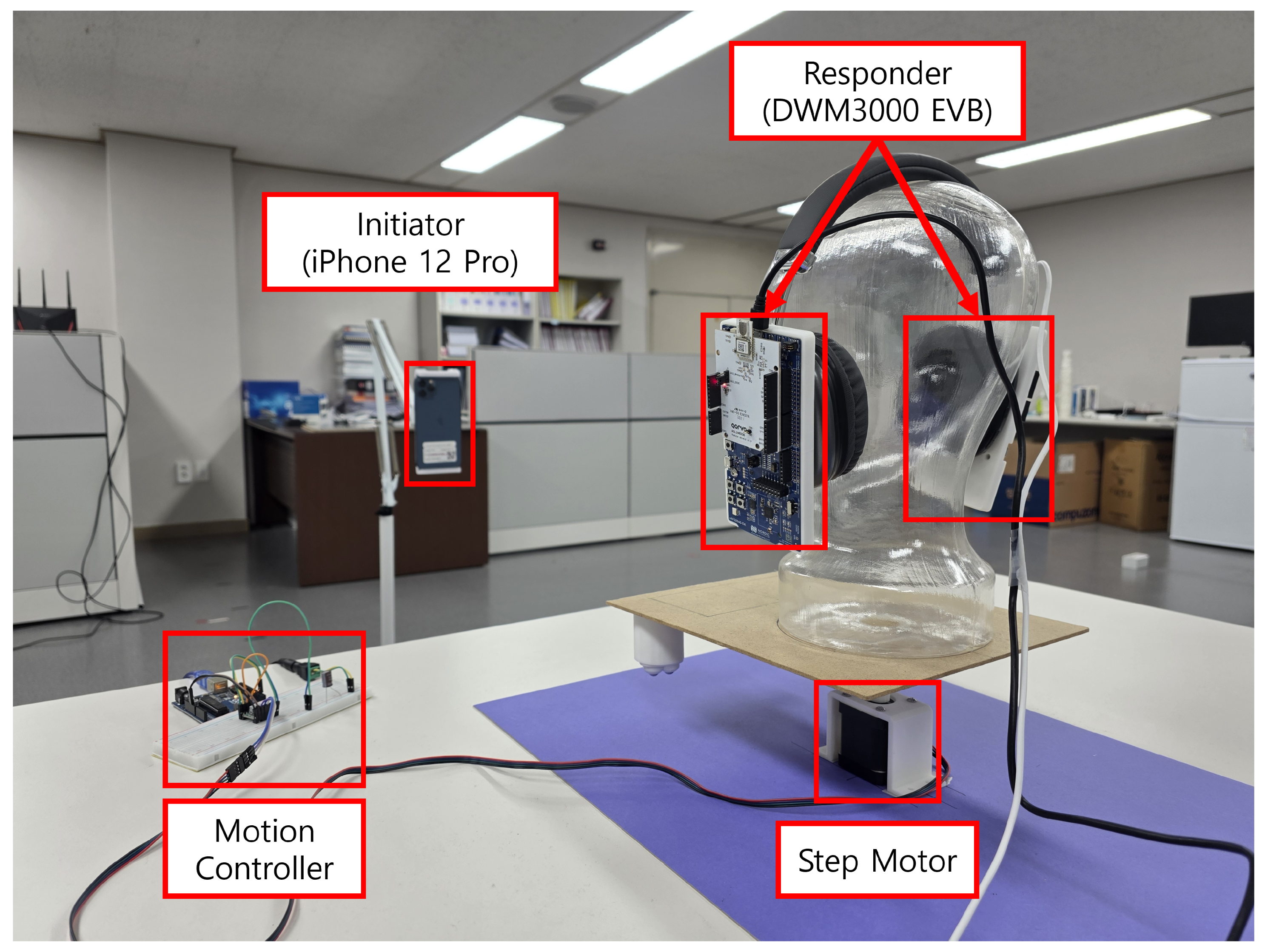
5.1. Experimental Setup

The experimental hardware consists of a responder–initiator pair for UWB signal exchange and a step-motor-based motion controller for precise heading direction adjustment. An iPhone 12 Pro (Apple, Cupertino, CA, USA) serves as the UWB initiator, while Qorvo DWM3000EVB and nRF52840-DK (Qorvo Inc., Greensboro, NC, USA) modules act as responders. Since UWB wireless earbuds are not yet readily available, we used the dedicated devices as responders compatible with the initiator. To accurately control the heading direction of a dummy head fitted with these responders at both ears, we employed 42BYGHW811 step motors (Wantai Motor, Beijing, China) driven by A4988 step motor drivers (Allegro Microsystems, Manchester, NH, USA), all coordinated by an Arduino Uno-based motion controller (Arduino, Chiasso, Switzerland).
Communication between the initiator and each responder was implemented using Apple’s Nearby Interaction framework (version 3.2.1). Due to the framework’s constraints, we were required to use UWB channel 9 (center frequency 7.9872 GHz), and we kept DS-TWR parameters at their default values. An initial session was established over Bluetooth via Apple’s Nearby Interaction framework, followed by UWB communication to acquire distance and direction measurements, which were then used for ear position estimation.
For performance comparison of our EKF-based heading direction tracking, we adopt the state-of-the-art IMU-based orientation tracker MUSE [67] as our baseline. MUSE tracks orientation by integrating gyroscope measurements and calibrates against the magnetometer’s magnetic vector. To further enhance calibration precision, it also performs opportunistic recalibration using accelerometer data.
MUSE is rigidly attached to and rotated with the dummy head, providing direct measurements of heading direction. In contrast, our proposed method infers heading indirectly from the xz-plane coordinates of the ear-mounted responders. For a fair comparison, we define the following:
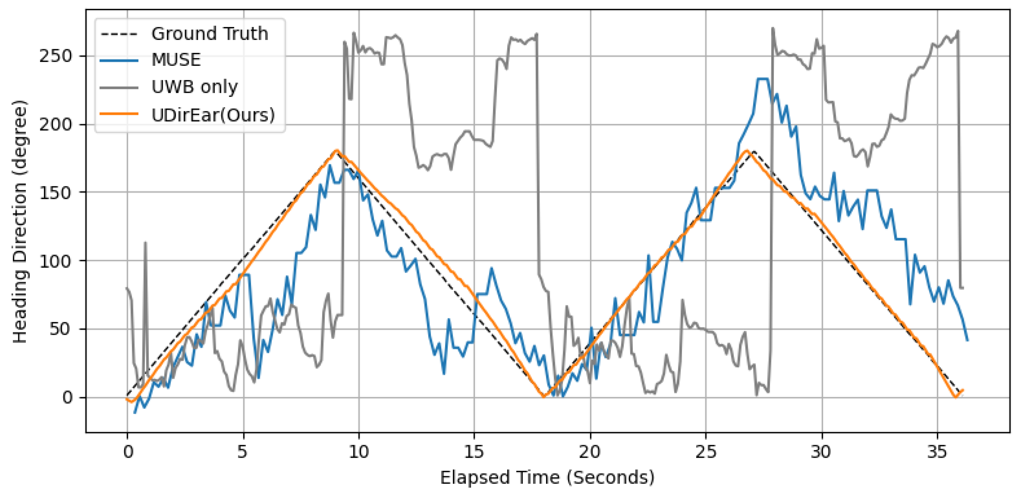
  • Ground Truth: The angular trajectory pre-programmed into the dummy head.
  • Metric: The mean absolute error (MAE) between the predefined trajectory and estimated heading.

5.2. Experimental Results

In this subsection, we describe the experiments conducted to verify the performance and robustness of UDirEar and present the corresponding results. The main experiment compares the performance of UDirEar with that of MUSE, demonstrating the better performance of our approach. Subsequent experiments examine the influence of dummy head–initiator distance, elapsed time, the inclusion of EKF filtering, and NLoS conditions on performance.

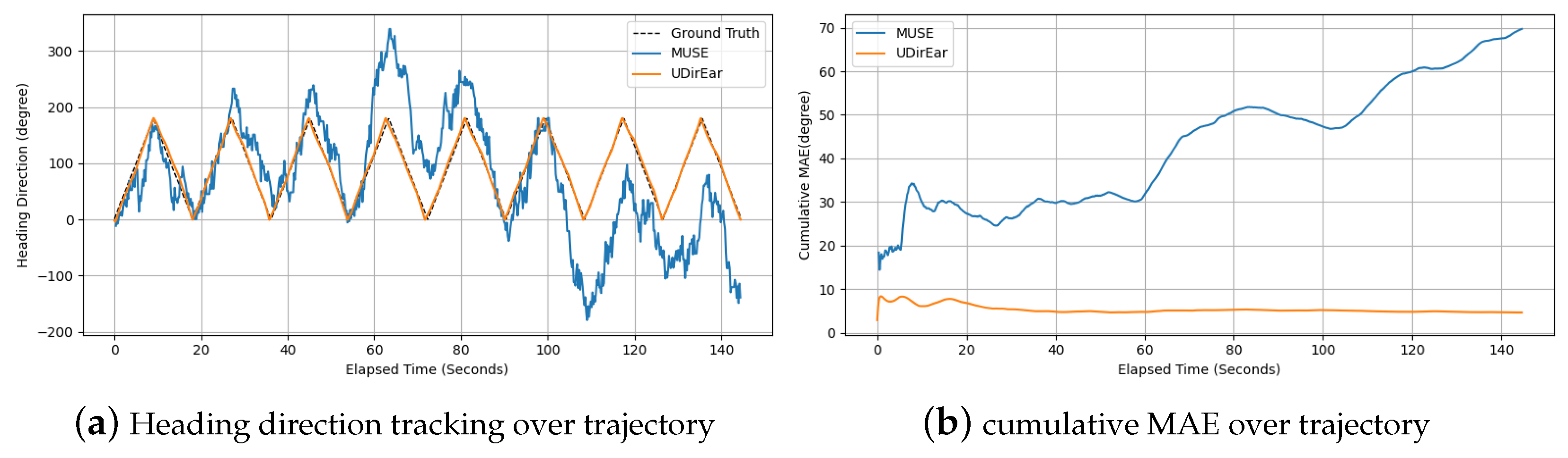
5.2.1. Comparison Between Baseline and UDirEar

In our experiments, we use the dummy head’s predefined angular trajectory as the ground truth and adopt the MAE between each estimated heading and the ground truth as our main metric. Proper trajectory design is therefore essential to accurately assess tracking performance. Since the human neck typically rotates over a 0 ° –180 ° range without torso movement, we employ a back-and-forth trajectory from 0 ° to 180 ° in all subsequent tests.
Figure 4 shows the time-resolved heading trajectories of UWB only, UDirEar (10 Hz update rate, 3 m dummy head–initiator distance), and MUSE (5Hz update rate) against the ground truth (two cycles of 0 ° →180 ° →0 ° ). UWB only is the same method as UDirEar but without EKF-based calibration. In this section, we compare MUSE with UDirEar and UWB only with UDirEar, evaluating UDirEar against these baselines and investigating how EKF-based calibration affects UDirEar’s performance.
Both MUSE and UDirEar capture the overall triangular trend, but MUSE exhibits considerable jitter and coarser steps, whereas UDirEar follows the trajectory more smoothly and with finer detail. This difference arises because UDirEar relies solely on the measurements at time t to estimate the heading direction at time t, whereas MUSE incorporates the entire measurement history from time 0 to t. Since MUSE incorporates all measurements from time 0 up to the current instant, the errors at each step accumulate into a cumulative error, which can lead to performance degradation. Furthermore, UDirEar infers heading from the xz-plane coordinates of ear-mounted UWB sensors and uses an EKF to compensate for the current step’s measurement error.
The impact of this gyroscope noise becomes apparent when comparing the MAE of each method over the full trajectory. MUSE incurs an average error of 30.78 ° , whereas UDirEar achieves only 3.84 ° , demonstrating that our approach substantially outperforms the baseline within the typical 0 ° –180 ° head motion range.
Figure 4 plots the tracking over the trajectory for UWB only and UDirEar. Although both exhibit the same periodic trend, the UWB-only curve shows large, erratic deviations from the ground truth path, yielding an MAE of 99.48 ° . In contrast, UDirEar closely follows the trajectory, with an MAE of 3.84 ° .
The core reason the UWB-only method exhibits a high MAE is the nonlinear error propagation that occurs when converting the two ear positions into a heading direction. In practice, the two sensors have different noise characteristics, each with its own variance and fixed bias. We compute the heading θ as Equation (13). Here, small errors Δ x = ( x r x l ) and Δ z = ( z r z l ) propagate nonlinearly into θ . In particular, when Δ z is small, a given position error translates into a much larger angular error, so any difference in sensor variance or bias is magnified into a steep rise in MAE.
Without an EKF, simply averaging or weighted-averaging two noisy measurements cannot compensate for this nonlinear amplification, and the MAE remains high. By contrast, the EKF’s update step uses each sensor noise covariance matrix R to assign more weight to the more reliable sensor (smaller variance) and less weight to the less reliable one (larger variance).

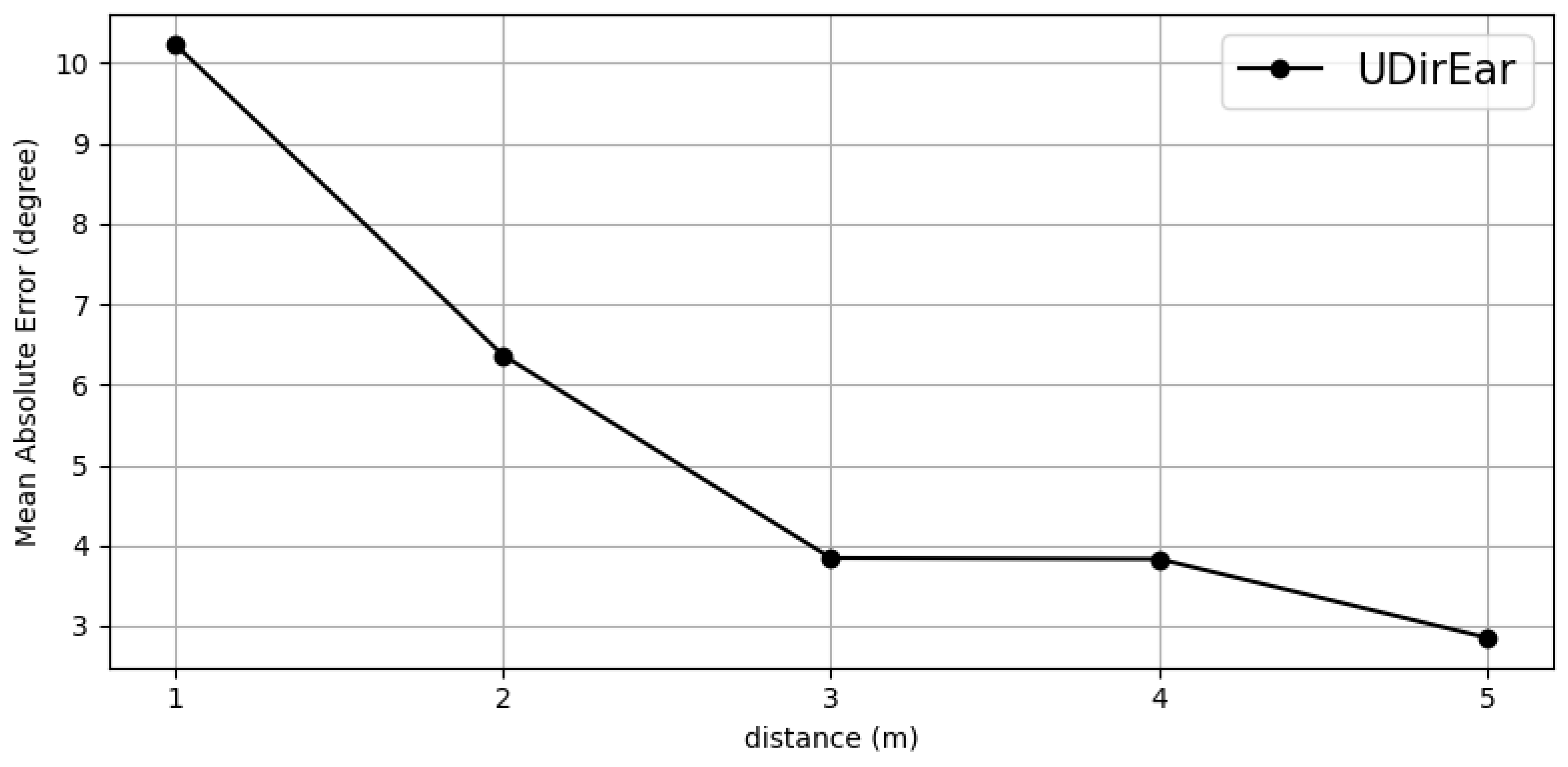
5.2.2. Effect of Distance Between Dummy Head and Initiator

The goal of this experiment is to assess how the distance between the dummy head and initiator affects heading tracking accuracy. Because signal attenuation at longer ranges can degrade performance, we measured the MAE over the full trajectory as the dummy head and the initiator were placed at distances of 1 m, 2 m, 3 m, 4 m, and 5 m.
All tests were conducted in the indoor environment shown in Figure 5. Five meters was the maximum feasible range in our laboratory.
Figure 6 shows the results. We observed mean errors of 10.23 ° , 6.37 ° , 3.84 ° , 3.83 ° , and 2.85 ° at distances of 1 m, 2 m, 3 m, 4 m, and 5 m, respectively. Contrary to expectations of higher errors at longer distances due to attenuation, the data show larger errors at shorter ranges. This outcome is due to the fixed distance-independent bias in UWB ranging. A constant offset error becomes a larger fraction of the true range at close distances [68,69,70]. In addition, UWB ranging accuracy remains roughly constant over these short indoor distances [50], so the fixed bias dominates performance at 1 m.
Although our experiments only cover distances up to 5 m, this range is sufficient to evaluate the distance-dependent robustness of our method for wireless earbud-based heading tracking.

5.2.3. Effect of Elapsed Time

Conventional IMU-based approaches including MUSE rely primarily on gyroscope integration for heading tracking. Gyroscope drift introduces cumulative error over time, so these methods are not well suited for long-term use. To address this, prior work has combined a gyroscope with UWB or additional IMU sensors for periodic correction [26,47,50,67].
In this experiment we extended the predefined trajectory (eight cycles of 0 ° →180 ° →0 ° ) to observe how tracking performance evolves over longer intervals. We evaluate performance using the cumulative MAE, which is defined as the MAE from the start of tracking up to each elapsed time.
Figure 7a presents the tracking result over time of MUSE and UDirEar against the ground truth. Both methods capture the overall pattern of counterclockwise rotation from 0 ° to 180 ° followed by clockwise return to 0 ° ; however MUSE’s estimates gradually diverge due to accumulating gyroscope drift despite its internal correction.
Figure 7b plots the cumulative MAE over elapsed time. Although there is some initial jitter, UDirEar maintains an almost flat cumulative MAE, whereas MUSE’s error grows continuously. By the end of the trajectory, the cumulative MAE of our approach is 4.65 ° , compared with 69.71 ° for MUSE. This dramatic difference demonstrates that UDirEar provides stable tracking over a long time.

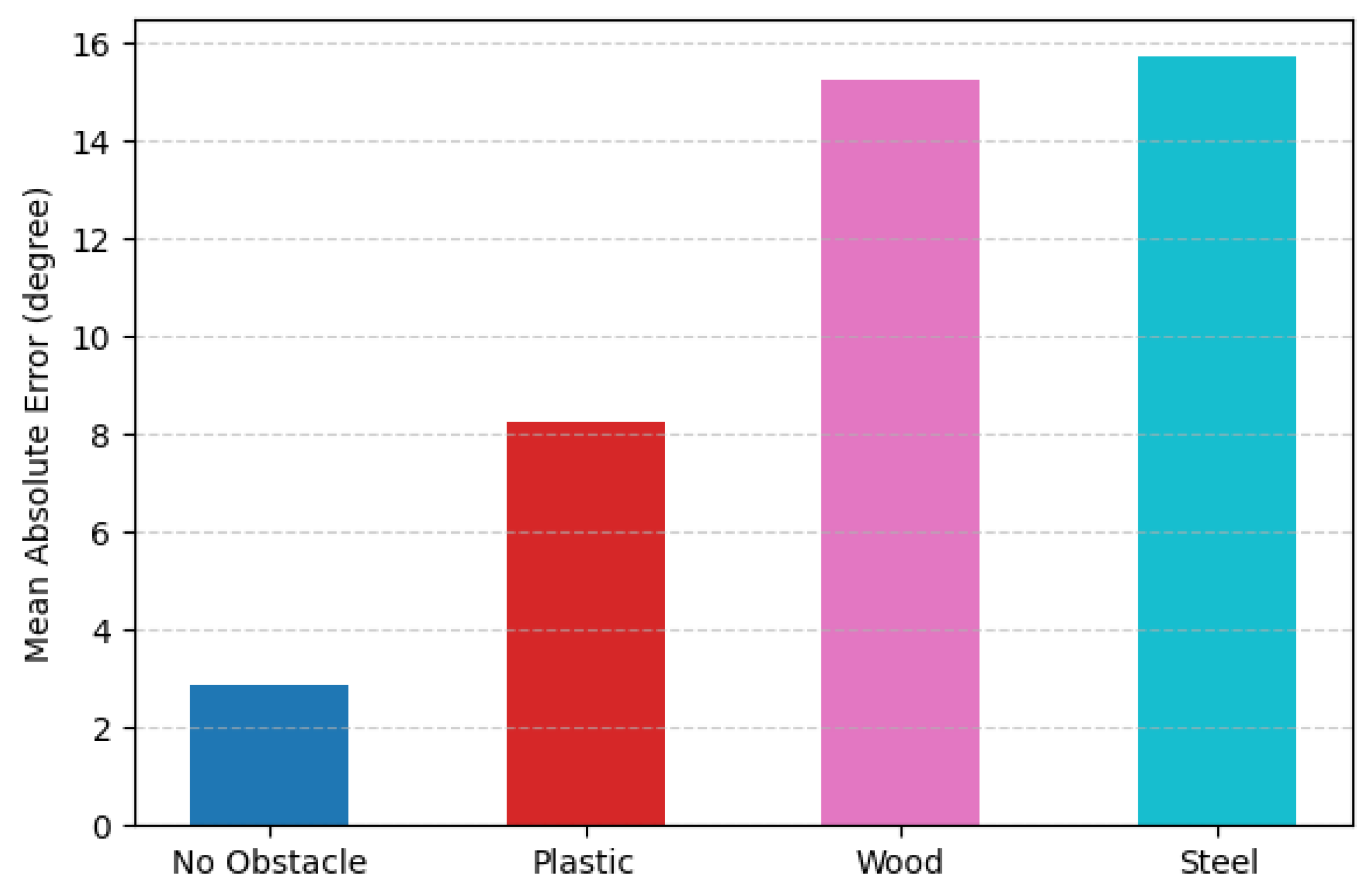
5.2.4. Effect of NLoS by Occlusion

In practice, our method infers heading from ear-mounted UWB sensors, but the geometry of the head makes it unlikely that both ears remain in LoS to the initiator. To evaluate robustness under NLoS conditions, we placed a 50 × 80 cm rectangular panel between the dummy head and initiator at a 5 m separation, creating three NLoS scenarios with plastic, wood, and steel occluders.
Figure 8 shows the MAE for LoS (no obstacle) and each NLoS case. This error increases from 2.85 ° in LoS to 8.23 ° with plastic, 15.24 ° with wood, and 15.69 ° with steel. This drop in performance is due to occlusion-induced UWB signal attenuation, which reduces range accuracy and degrades angular precision. Materials inducing greater signal attenuation correspond to higher measurement errors, with steel exhibiting the strongest attenuation and producing the largest error, followed by wood and then plastic.

6. Discussion

6.1. IMU-Enhanced Initiator Initialization and Tracking

In UDirEar, the initiator was used with its fixed position, but our future goal is to operate without fixing the initiator’s position. As shown in Section 5.2.4, relying solely on UWB measurements without EKF calibration can lead to degraded measurement performance. In UDirEar, the energy constraints of wireless earbuds necessitate the use of UWB-only measurements, and because the Parameter Initialization stage does not employ the EKF, the precision of the initialized parameters may be low. Using a initiator with fewer energy constraints such as a smartphone with a built-in IMU and fusing its inertial data with UWB measurements during initialization can significantly enhance the precision of the initial parameter estimates. Since our initiator can also integrate an IMU, future work will fuse IMU data both at startup and online. During initialization, IMU alignment will refine the initiator position, interaural distance, and initial state to correct UWB bias. In filtering, the EKF will combine continuous IMU and UWB updates to track the initiator’s motion in real time rather than holding its position fixed. This IMU and UWB fusion should yield a more flexible, accurate heading estimator without modifying the responder.

6.2. Fine-Grained Practical Head Movement Tracking

To simplify computation, UDirEar currently projects both ear positions onto the xz-plane and estimates heading direction in that plane. However, our evaluation relied on a dummy head model, so we have not yet characterized the additional signal delay and attenuation effects introduced by a real human’s head. Moreover, because UDirEar only tracks yaw when the interaural axis lies approximately in the xz-plane, its applicability is currently confined to these constrained motion scenarios. However, full three-dimensional orientation offers richer motion capture. In future work, if the UWB API evolves to provide limited low-level details or to allow user-defined DS-TWR configurations [71], additional CIR-related measurements could be exploited for finer-grained ranging and directional estimation. In that scenario, for 3D head movement tracking, instead of using only direction vectors, we would construct quaternions from this richer information and integrate them into the EKF framework.

6.3. Heading Direction Application in Daily Life

Heading direction tracking with UDirEar can enable a variety of daily applications, including VR/AR interfaces, navigation systems, and attention-aware controls. Because it uses COTS UWB hardware and sensors mounted at the ears, it can be easily integrated into existing VR/AR headsets, allowing the system to render visuals and spatial audio based on the user’s real-time heading direction. In navigation, head tracking can guide users by indicating which way to turn or highlighting points of interest in their field of view. Finally, in attention-aware control scenarios, the system can detect when the user is looking at a display or object and automatically switch it on or off, improving convenience and energy efficiency.

7. Conclusions

In this paper, we propose a method that uses only UWB sensors embedded in wireless earbuds and an extended Kalman filter to track heading direction under roto-translational motion. We exclude IMUs to minimize energy consumption and rely solely on UWB measurements. An EKF is applied to correct for and fuse the bias and variance of the two ear-mounted sensors. To verify robustness, we compared our method against an IMU-based approach and evaluated the effects of distance, elapsed time, EKF configuration, and NLoS conditions. These experiments yielded an MAE of 3.84 ° .

Author Contributions

Conceptualization, M.K. and J.K.; methodology, M.K.; software, M.K.; validation, M.K., Y.N., J.K. and Y.-J.S.; formal analysis, M.K.; investigation, M.K., Y.N. and J.K.; resources, Y.-J.S.; data curation, M.K.; writing—original draft preparation, M.K., Y.N. and J.K.; writing—review and editing, M.K., Y.N., J.K. and Y.-J.S.; visualization, M.K. and J.K.; supervision, Y.-J.S.; project administration, M.K. and Y.-J.S.; funding acquisition, Y.-J.S. All authors have read and agreed to the published version of the manuscript.

Funding

This research was partly supported by Basic Science Research Program through the National Research Foundation of Korea (NRF) funded by the Ministry of Education (RS-2022-NR070870), Institute of Information & Communications Technology Planning & Evaluation (IITP) grant funded by the Korea government (MSIT) (No. RS-2019-II191906, Artificial Intelligence Graduate School Program (POSTECH)).

Data Availability Statement

The datasets presented in this article are not readily available, due to an another ongoing study with overlaps in the dataset. Requests to access the datasets should be directed to the authors of the article.

Conflicts of Interest

The authors declare no conflicts of interest.

References

  1. LaValle, S.M.; Yershova, A.; Katsev, M.; Antonov, M. Head tracking for the Oculus Rift. In Proceedings of the 2014 IEEE International Conference on Robotics and Automation (ICRA), Hong Kong, China, 31 May–7 June 2014; pp. 187–194. [Google Scholar] [CrossRef]
  2. Banaszczyk, A.; Lysakowski, M.; Nowicki, M.R.; Skrzypczynski, P.; Tadeja, S.K. How Accurate is the Positioning in VR? Using Motion Capture and Robotics to Compare Positioning Capabilities of Popular VR Headsets. In Proceedings of the 2024 IEEE International Symposium on Mixed and Augmented Reality Adjunct (ISMAR-Adjunct), Bellevue, WA, USA, 21–25 October 2024; pp. 79–86. [Google Scholar] [CrossRef]
  3. Vox, J.P.; Weber, A.; Wolf, K.I.; Izdebski, K.; Schüler, T.; König, P.; Wallhoff, F.; Friemert, D. An Evaluation of Motion Trackers with Virtual Reality Sensor Technology in Comparison to a Marker-Based Motion Capture System Based on Joint Angles for Ergonomic Risk Assessment. Sensors 2021, 21, 3145. [Google Scholar] [CrossRef]
  4. Cutolo, F.; Mamone, V.; Carbonaro, N.; Ferrari, V.; Tognetti, A. Ambiguity-Free Optical–Inertial Tracking for Augmented Reality Headsets. Sensors 2020, 20, 1444. [Google Scholar] [CrossRef]
  5. Franček, P.; Jambrošić, K.; Horvat, M.; Planinec, V. The Performance of Inertial Measurement Unit Sensors on Various Hardware Platforms for Binaural Head-Tracking Applications. Sensors 2023, 23, 872. [Google Scholar] [CrossRef]
  6. Hoang, M.L.; Carratù, M.; Paciello, V.; Pietrosanto, A. Fusion Filters between the No Motion No Integration Technique and Kalman Filter in Noise Optimization on a 6DoF Drone for Orientation Tracking. Sensors 2023, 23, 5603. [Google Scholar] [CrossRef]
  7. Kuti, J.; Piricz, T.; Galambos, P. A Robust Method for Validating Orientation Sensors Using a Robot Arm as a High-Precision Reference. Sensors 2024, 24, 8179. [Google Scholar] [CrossRef]
  8. Hu, L.; Tang, Y.; Zhou, Z.; Pan, W. Reinforcement Learning for Orientation Estimation Using Inertial Sensors with Performance Guarantee. In Proceedings of the 2021 IEEE International Conference on Robotics and Automation (ICRA), Xi’an, China, 30 May–5 June 2021; pp. 10243–10249. [Google Scholar] [CrossRef]
  9. Zhang, J.Y.; Lin, A.; Kumar, M.; Yang, T.H.; Ramanan, D.; Tulsiani, S. Cameras as Rays: Pose Estimation via Ray Diffusion. In Proceedings of the Twelfth International Conference on Learning Representations, Vienna, Austria, 7–11 May 2024. [Google Scholar]
  10. de Medeiros Esper, I.; Smolkin, O.; Manko, M.; Popov, A.; From, P.J.; Mason, A. Evaluation of RGB-D Multi-Camera Pose Estimation for 3D Reconstruction. Appl. Sci. 2022, 12, 4134. [Google Scholar] [CrossRef]
  11. Chen, F.; Wu, Y.; Liao, T.; Zeng, H.; Ouyang, S.; Guan, J. GMIW-Pose: Camera Pose Estimation via Global Matching and Iterative Weighted Eight-Point Algorithm. Electronics 2023, 12, 4689. [Google Scholar] [CrossRef]
  12. Yen-Chen, L.; Florence, P.; Barron, J.T.; Rodriguez, A.; Isola, P.; Lin, T.Y. iNeRF: Inverting Neural Radiance Fields for Pose Estimation. In Proceedings of the 2021 IEEE/RSJ International Conference on Intelligent Robots and Systems (IROS), Prague, Czech Republic, 27 September–1 October 2021; IEEE Press: Piscataway, NJ, USA, 2021; pp. 1323–1330. [Google Scholar] [CrossRef]
  13. Li, J.; Liu, K.; Wu, J. Ego-Body Pose Estimation via Ego-Head Pose Estimation. In Proceedings of the IEEE/CVF Conference on Computer Vision and Pattern Recognition, Vancouver, BC, Canada, 17–24 June 2023; pp. 17142–17151. [Google Scholar]
  14. Wu, M.Y.; Ting, P.W.; Tang, Y.H.; Chou, E.T.; Fu, L.C. Hand pose estimation in object-interaction based on deep learning for virtual reality applications. J. Vis. Commun. Image Represent. 2020, 70, 102802. [Google Scholar] [CrossRef]
  15. Mao, W.; He, J.; Qiu, L. CAT: High-precision acoustic motion tracking. In Proceedings of the MobiCom’16: 22nd Annual International Conference on Mobile Computing and Networking, New York, NY, USA, 3–7 October 2016; pp. 69–81. [Google Scholar] [CrossRef]
  16. Yang, Z.; Wei, Y.L.; Shen, S.; Choudhury, R.R. Ear-AR: Indoor acoustic augmented reality on earphones. In Proceedings of the MobiCom’20: 26th Annual International Conference on Mobile Computing and Networking, London, UK, 21–25 September 2020. [Google Scholar] [CrossRef]
  17. Hu, J.; Jiang, H.; Liu, D.; Xiao, Z.; Zhang, Q.; Liu, J.; Dustdar, S. Combining IMU With Acoustics for Head Motion Tracking Leveraging Wireless Earphone. IEEE Trans. Mob. Comput. 2024, 23, 6835–6847. [Google Scholar] [CrossRef]
  18. Zhou, H.; Lu, T.; Liu, Y.; Zhang, S.; Liu, R.; Gowda, M. One Ring to Rule Them All: An Open Source Smartring Platform for Finger Motion Analytics and Healthcare Applications. In Proceedings of the IoTDI’23: 8th ACM/IEEE Conference on Internet of Things Design and Implementation, San Antonio, TX, USA, 9–12 May 2023; pp. 27–38. [Google Scholar] [CrossRef]
  19. Zhou, P.; Li, M.; Shen, G. Use it free: Instantly knowing your phone attitude. In Proceedings of the MobiCom’14: 20th Annual International Conference on Mobile Computing and Networking, Maui, HI, USA, 7–11 September 2014; pp. 605–616. [Google Scholar] [CrossRef]
  20. Kumar, A.; Pundlik, S.; Peli, E.; Luo, G. Comparison of Visual SLAM and IMU in Tracking Head Movement Outdoors. Behav. Res. Methods 2023, 55, 2787–2799. [Google Scholar] [CrossRef]
  21. Ferlini, A.; Montanari, A.; Grammenos, A.; Harle, R.; Mascolo, C. Enabling In-Ear Magnetic Sensing: Automatic and User Transparent Magnetometer Calibration. In Proceedings of the 2021 IEEE International Conference on Pervasive Computing and Communications (PerCom), Kassel, Germany, 22–26 March 2021; pp. 1–8. [Google Scholar] [CrossRef]
  22. Ferlini, A.; Montanari, A.; Mascolo, C.; Harle, R. Head Motion Tracking Through in-Ear Wearables. In Proceedings of the EarComp’19: 1st International Workshop on Earable Computing, London, UK, 9 September 2020; pp. 8–13. [Google Scholar] [CrossRef]
  23. Hinterstoisser, S.; Lepetit, V.; Ilic, S.; Fua, P.; Navab, N. Dominant orientation templates for real-time detection of texture-less objects. In Proceedings of the 2010 IEEE Computer Society Conference on Computer Vision and Pattern Recognition, San Francisco, CA, USA, 13–18 June 2010; pp. 2257–2264. [Google Scholar] [CrossRef]
  24. Shi, Y.; Yu, X.; Campbell, D.; Li, H. Where Am I Looking At? Joint Location and Orientation Estimation by Cross-View Matching. In Proceedings of the 2020 IEEE/CVF Conference on Computer Vision and Pattern Recognition (CVPR), Seattle, WA, USA, 13–19 June 2020; pp. 4063–4071. [Google Scholar] [CrossRef]
  25. Sundermeyer, M.; Marton, Z.C.; Durner, M.; Brucker, M.; Triebel, R. Implicit 3D Orientation Learning for 6D Object Detection from RGB Images. In Proceedings of the European Conference on Computer Vision (ECCV), Munich, Germany, 8–14 September 2018. [Google Scholar]
  26. Zhao, Y.; Görne, L.; Yuen, I.M.; Cao, D.; Sullman, M.; Auger, D.; Lv, C.; Wang, H.; Matthias, R.; Skrypchuk, L.; et al. An Orientation Sensor-Based Head Tracking System for Driver Behaviour Monitoring. Sensors 2017, 17, 2692. [Google Scholar] [CrossRef]
  27. Xie, X.; Shin, K.G.; Yousefi, H.; He, S. Wireless CSI-based head tracking in the driver seat. In Proceedings of the CoNEXT’18: 14th International Conference on Emerging Networking Experiments and Technologies, Heraklion, Greece, 4–7 December 2018; pp. 112–125. [Google Scholar] [CrossRef]
  28. Cao, G.; Yuan, K.; Xiong, J.; Yang, P.; Yan, Y.; Zhou, H.; Li, X.Y. EarphoneTrack: Involving earphones into the ecosystem of acoustic motion tracking. In Proceedings of the SenSys’20: 18th Conference on Embedded Networked Sensor Systems, Virtual Event, Japan, 16–19 November 2020; pp. 95–108. [Google Scholar] [CrossRef]
  29. Wang, A.; Gollakota, S. MilliSonic: Pushing the Limits of Acoustic Motion Tracking. In Proceedings of the CHI’19: 2019 CHI Conference on Human Factors in Computing Systems, Glasgow, UK, 4–9 May 2019; pp. 1–11. [Google Scholar] [CrossRef]
  30. Wang, Y.; Ding, J.; Chatterjee, I.; Salemi Parizi, F.; Zhuang, Y.; Yan, Y.; Patel, S.; Shi, Y. FaceOri: Tracking Head Position and Orientation Using Ultrasonic Ranging on Earphones. In Proceedings of the CHI’22: 2022 CHI Conference on Human Factors in Computing Systems, New Orleans, LA, USA, 29 April–5 May 2022. [Google Scholar] [CrossRef]
  31. Ge, L.; Zhang, Q.; Zhang, J.; Chen, H. EHTrack: Earphone-Based Head Tracking via Only Acoustic Signals. IEEE Internet Things J. 2024, 11, 4063–4075. [Google Scholar] [CrossRef]
  32. Hu, J.; Jiang, H.; Xiao, Z.; Chen, S.; Dustdar, S.; Liu, J. HeadTrack: Real-Time Human–Computer Interaction via Wireless Earphones. IEEE J. Sel. Areas Commun. 2024, 42, 990–1002. [Google Scholar] [CrossRef]
  33. Venkatnarayan, R.H.; Shahzad, M.; Yun, S.; Vlachou, C.; Kim, K.H. Leveraging Polarization of WiFi Signals to Simultaneously Track Multiple People. Proc. ACM Interact. Mob. Wearable Ubiquitous Technol. 2022, 4, 1–24. [Google Scholar] [CrossRef]
  34. Wang, H.; Sen, S.; Elgohary, A.; Farid, M.; Youssef, M.; Choudhury, R.R. No need to war-drive: Unsupervised indoor localization. In Proceedings of the MobiSys’12: 10th International Conference on Mobile Systems, Applications, and Services, Ambleside, UK, 25–29 June 2012; pp. 197–210. [Google Scholar] [CrossRef]
  35. Jiang, C.; He, Y.; Zheng, X.; Liu, Y. OmniTrack: Orientation-Aware RFID Tracking With Centimeter-Level Accuracy. IEEE Trans. Mob. Comput. 2021, 20, 634–646. [Google Scholar] [CrossRef]
  36. Wei, T.; Zhang, X. Gyro in the air: Tracking 3D orientation of batteryless internet-of-things. In Proceedings of the MobiCom’16: 22nd Annual International Conference on Mobile Computing and Networking, New York, NY, USA, 3–7 October 2016; pp. 55–68. [Google Scholar] [CrossRef]
  37. Apple Inc. Apple iPhone 14—Specifications. 2022. Available online: https://www.apple.com/iphone-14/specs (accessed on 30 May 2025).
  38. Apple Inc. Apple iPhone 15—Specifications. 2023. Available online: https://www.apple.com/iphone-15/specs (accessed on 30 May 2025).
  39. Apple Inc. Apple iPhone 16—Specifications. 2024. Available online: https://www.apple.com/iphone-16/specs (accessed on 30 May 2025).
  40. Samsung Electronics. Samsung Galaxy S25 Ultra—Specifications. 2025. Available online: https://www.samsung.com/us/smartphones/galaxy-s25-ultra (accessed on 30 May 2025).
  41. Samsung China Semiconductor Co., Ltd.; Samsung Electronics Co., Ltd. Method and Apparatus for Controlling Wireless Headphones and Headphone System. CN117041792A, November 2023. Available online: https://patents.google.com/patent/CN117041792A/en (accessed on 16 June 2025).
  42. Arun, A.; Saruwatari, S.; Shah, S.; Bharadia, D. XRLoc: Accurate UWB Localization to Realize XR Deployments. In Proceedings of the SenSys’23: 21st ACM Conference on Embedded Networked Sensor Systems, Istanbul, Turkiye, 12–17 November 2024; pp. 459–473. [Google Scholar] [CrossRef]
  43. Cao, Y.; Dhekne, A.; Ammar, M. ViSig: Automatic Interpretation of Visual Body Signals Using On-Body Sensors. In Proceedings of the ACM on Interactive, Mobile, Wearable and Ubiquitous Technologies; Association for Computing Machinery: New York, NY, USA, 2023; Volume 7, pp. 1–27. [Google Scholar] [CrossRef]
  44. Kempke, B.; Pannuto, P.; Dutta, P. Harmonium: Asymmetric, Bandstitched UWB for Fast, Accurate, and Robust Indoor Localization. In Proceedings of the 2016 15th ACM/IEEE International Conference on Information Processing in Sensor Networks (IPSN), Vienna, Austria, 11–14 April 2016; pp. 1–12. [Google Scholar] [CrossRef]
  45. Feng, D.; Wang, C.; He, C.; Zhuang, Y.; Xia, X.G. Kalman-Filter-Based Integration of IMU and UWB for High-Accuracy Indoor Positioning and Navigation. IEEE Internet Things J. 2020, 7, 3133–3146. [Google Scholar] [CrossRef]
  46. Gowda, M.; Dhekne, A.; Shen, S.; Choudhury, R.R.; Yang, L.; Golwalkar, S.; Essanian, A. Bringing IoT to Sports Analytics. In Proceedings of the 14th USENIX Symposium on Networked Systems Design and Implementation (NSDI 17), Boston, MA, USA, 27–29 March 2017; pp. 499–513. [Google Scholar]
  47. Cao, Y.; Dhekne, A.; Ammar, M. ITrackU: Tracking a pen-like instrument via UWB-IMU fusion. In Proceedings of the MobiSys’21; 19th Annual International Conference on Mobile Systems, Applications, and Services, Virtual Event, WI, USA, 24 June–2 July 2021; pp. 453–466. [Google Scholar] [CrossRef]
  48. Zhang, J.; Wang, J. FusionTrack: Towards Accurate Device-free Acoustic Motion Tracking with Signal Fusion. ACM Trans. Sens. Netw. 2024, 20, 1–30. [Google Scholar] [CrossRef]
  49. Xu, C.; Zheng, X.; Ren, Z.; Liu, L.; Ma, H. UHead: Driver Attention Monitoring System Using UWB Radar. Proc. ACM Interact. Mob. Wearable Ubiquitou Technol. 2024, 8, 1–28. [Google Scholar] [CrossRef]
  50. Zhou, H.; Yuan, K.; Gowda, M.; Qiu, L.; Xiong, J. Rethinking Orientation Estimation with Smartphone-equipped Ultra-wideband Chips. In Proceedings of the ACM MobiCom’24: 30th Annual International Conference on Mobile Computing and Networking, Washington, DC, USA, 18–22 November 2024; pp. 1045–1059. [Google Scholar] [CrossRef]
  51. Cao, Y.; Dhekne, A.; Ammar, M. UTrack3D: 3D Tracking Using Ultra-wideband (UWB) Radios. In Proceedings of theMOBISYS’24: 22nd Annual International Conference on Mobile Systems, Applications and Services, Tokyo, Japan, 3–7 June 2024; pp. 345–358. [Google Scholar] [CrossRef]
  52. IEEE Std 802.15.4-2020; Revision of IEEE Std 802.15.4-2015, IEEE Standard for Low-Rate Wireless Networks. IEEE: New York, NY, USA, 2020; pp. 1–800. [CrossRef]
  53. Apple Inc. Apple Watch Series 10—Specifications. 2024. Available online: https://www.apple.com/apple-watch-series-10 (accessed on 30 May 2025).
  54. Google Inc. Google Pixel Watch 3—Specifications. 2024. Available online: https://store.google.com/gb/product/pixel_watch_3_specs (accessed on 30 May 2025).
  55. Apple Inc. Nearby Interaction API. Available online: https://developer.apple.com/documentation/nearbyinteraction (accessed on 30 May 2025).
  56. Google Inc. Android Ultra-Wideband (UWB) API. Available online: https://developer.android.com/develop/connectivity/uwb (accessed on 30 May 2025).
  57. Neirynck, D.; Luk, E.; McLaughlin, M. An alternative double-sided two-way ranging method. In Proceedings of the 2016 13th Workshop on Positioning, Navigation and Communications (WPNC), Bremen, Germany, 19–20 October 2016; pp. 1–4. [Google Scholar]
  58. Montañez, O.J.; Suárez, M.J.; Fernández, E.A. Application of Data Sensor Fusion Using Extended Kalman Filter Algorithm for Identification and Tracking of Moving Targets from LiDAR–Radar Data. Remote Sens. 2023, 15, 3396. [Google Scholar] [CrossRef]
  59. Yin, Y.; Zhang, J.; Guo, M.; Ning, X.; Wang, Y.; Lu, J. Sensor Fusion of GNSS and IMU Data for Robust Localization via Smoothed Error State Kalman Filter. Sensors 2023, 23, 3676. [Google Scholar] [CrossRef] [PubMed]
  60. Deng, Z.A.; Hu, Y.; Yu, J.; Na, Z. Extended Kalman Filter for Real Time Indoor Localization by Fusing WiFi and Smartphone Inertial Sensors. Micromachines 2015, 6, 523–543. [Google Scholar] [CrossRef]
  61. Kalman, R.E. A New Approach to Linear Filtering and Prediction Problems. J. Basic Eng. 1960, 82, 35–45. [Google Scholar] [CrossRef]
  62. Welch, G.; Bishop, G. An Introduction to the Kalman Filter; Technical Report TR 95-041; University of North Carolina at Chapel Hill: Chapel Hill, NC, USA, 2006. [Google Scholar]
  63. Ribeiro, M.I. Kalman and Extended Kalman Filters: Concept, Derivation and Properties; Technical Report; Institute for Systems and Robotics, Instituto Superior Técnico, Universidade de Lisboa: Lisboa, Portugal, 2004. [Google Scholar]
  64. Zhang, F.; Chang, Z.; Xiong, J.; Ma, J.; Ni, J.; Zhang, W.; Jin, B.; Zhang, D. Embracing Consumer-level UWB-equipped Devices for Fine-grained Wireless Sensing. Proc. ACM Interact. Mob. Wearable Ubiquitous Technol. 2022, 6, 1–27. [Google Scholar] [CrossRef]
  65. Heuring, J.; Murray, D. Modeling and copying human head movements. IEEE Trans. Robot. Autom. 1999, 15, 1095–1108. [Google Scholar] [CrossRef]
  66. Bai, J.; He, X.; Jiang, Y.; Zhang, T.; Bao, M. Rotating One’s Head Modulates the Perceived Velocity of Motion Aftereffect. Multisensory Res. 2020, 33, 189–212. [Google Scholar] [CrossRef]
  67. Shen, S.; Gowda, M.; Roy Choudhury, R. Closing the Gaps in Inertial Motion Tracking. In Proceedings of the MobiCom’18: 24th Annual International Conference on Mobile Computing and Networking, New Delhi, India, 29 October–2 November 2018; pp. 429–444. [Google Scholar] [CrossRef]
  68. Awinic Technology Co., Ltd. DW1000 User Manual. 2021. Available online: https://www.sunnywale.com/uploadfile/2021/1230/DW1000%20User%20Manual_Awin.pdf (accessed on 10 June 2025).
  69. Shah, S.; Chaiwong, K.; Kovavisaruch, L.O.; Kaemarungsi, K.; Demeechai, T. Antenna Delay Calibration of UWB Nodes. IEEE Access 2021, 9, 63294–63305. [Google Scholar] [CrossRef]
  70. Preter, A.D.; Goysens, G.; Anthonis, J.; Swevers, J.; Pipeleers, G. Range Bias Modeling and Autocalibration of an UWB Positioning System. In Proceedings of the 2019 International Conference on Indoor Positioning and Indoor Navigation (IPIN), Pisa, Italy, 30 September–3 October 2019; pp. 1–8. [Google Scholar] [CrossRef]
  71. Han, S.; Jang, B.J. Extending the Coverage of IEEE 802.15.4z HRP UWB Ranging. Sensors 2025, 25, 3058. [Google Scholar] [CrossRef]
Figure 1. Distance and AoA estimation using UWB signals.
Electronics 14 02940 g001
Figure 2. (a) Illustration of UWB high-level information from COTS UWB devices in 3D Cartesian coordination. (b) Illustration of process model used in EKF heading direction; 2D coordinates mean coordinates of both ears in 2D Cartesian coordination where center of head is at origin.
Electronics 14 02940 g002
Figure 3. Illustration of overall heading direction system that runs on UWB devices. It fuses UWB sensor value with EKF process model that uses interaural distance to correct devices’ inefficient accuracy because of roto-translational motion.
Electronics 14 02940 g003
Figure 4. Heading direction tracking result comparison between MUSE, UWB only, and UDirEar. While all three methods effectively capture the periodic trend in heading direction, UDirEar captures fine-grained tracking details more effectively than MUSE, with the UWB-only approach yielding the least detailed tracking. The MAE for UDirEar, MUSE, and UWB only is 3.84 ° , 30.78 ° , and 99.48 ° , respectively.
Electronics 14 02940 g004
Figure 5. Experiment environment. Dummy head with two responders are controlled by step motor and motion controller.
Electronics 14 02940 g005
Figure 6. Effect of dummy head–initiator distance on performance. Heading error rises at close dummy head–initiator ranges due to UWB’s constant ranging bias.
Electronics 14 02940 g006
Figure 7. Effect of elapsed time on performance. UDirEar maintains stable performance over time, whereas MUSE’s performance degrades as elapsed time increases.
Electronics 14 02940 g007
Figure 8. Effect of occlusion on performance. UWB signal attenuation caused by occlusion leads to performance degradation.
Electronics 14 02940 g008
Table 1. Description of symbols used in the Kalman filter equations.
SymbolDescription
x ^ k  astate vector at step k
u k control input at step k
w k process model’s noise vector at step k
P k error covariance at step k
Q k process model’s noise covariance at step k
R k sensor value’s noise covariance at step k
S k residual noise covariance at step k
Astate transition matrix
Hobservation matrix
K k Kalman gain at step k
z k sensor value at step k
a—upper right position of symbol means this symbol is predicted value.
Disclaimer/Publisher’s Note: The statements, opinions and data contained in all publications are solely those of the individual author(s) and contributor(s) and not of MDPI and/or the editor(s). MDPI and/or the editor(s) disclaim responsibility for any injury to people or property resulting from any ideas, methods, instructions or products referred to in the content.

