1. Introduction
Under the “dual carbon” goal, the installed capacity of renewable energy, primarily wind and solar power, is constantly increasing, and its penetration rate in the power grid is steadily rising [
1,
2]. High-penetration distributed generation connecting to the grid, on the one hand, leads to a continuous increase in the proportion of power electronic converters, which are crucial interfaces for integrating new energy sources into the system, driving the power system towards a “dual-high” characteristic of a high proportion of renewable energy and a high proportion of power electronic equipment. On the other hand, the randomness and volatility of distributed generation can cause reverse power flow in the distribution network feeders, leading to an increase in bus voltage and, significantly deviating from the rated value. Simultaneously, the substantial increase in reactive loads like motors and lighting, along with the diversification of electrical equipment, has introduced various power quality issues in the distribution network, including three-phase unbalance, harmonic currents, voltage violations, and low power factor [
3,
4,
5,
6]. The voltage stability and inertia of the grid are also continuously decreasing.
To improve power quality, the reactive power compensator has become indispensable equipment. Existing reactive power compensation equipment includes synchronous condensers, capacitors, static VAR compensator, and distribution static synchronous compensator (DSTATCOM). DSTATCOM focuses on improving power quality issues and ensuring power supply reliability in distribution networks, and it can perform multiple functions including reactive power compensation, voltage regulation, and harmonic mitigation. It is a leading technology in the field of dynamic reactive power compensation for low-voltage distribution networks [
7]. Furthermore, with the increasing replacement of traditional rotating equipment by numerous power electronic devices, the inertia of renewable energy power generation systems and their immunity to disturbances have decreased. Integration of DC-side energy storage in DSTATCOM allows for four-quadrant power operation, enhancing its capability to provide both voltage support and inertia response [
8,
9].
For energy storage-type DSTATCOMs, harmonic and three-phase unbalance compensation of distribution networks requires detection and separation of positive-, negative-, and zero-sequence fundamental and harmonic components. The
method remains the most widely used detection method [
10], but the limited filtering effect of low-pass filters on the double-frequency harmonics generated by negative sequence components leads to unsatisfactory compensation performance. Reference [
11] proposed a three-phase four-wire DSTATCOM based on a modular multilevel converter. A proportional-integral controller with a dual
transformation is designed to suppress positive and negative sequence components, thereby compensating for unbalanced and reactive currents. Reference [
12], building upon the
harmonic detection method, obtained the negative-sequence fundamental component through negative-sequence coordinate transformation. A double-frequency notch filter is then placed after a low-pass filter to eliminate interference between positive and negative sequence currents. However, this method requires the system to provide additional active power, thus increasing system capacity. Reference [
13] proposed a method based on dual
-axis coordinate transformation that effectively separates positive and negative sequence fundamental components. However, the computational process is complex and requires stringent filter parameter design. This leads to a slow dynamic response and an inability to maintain balanced three-phase currents, requiring the injection of additional active power.
Reference [
14] applied VSG (Voltage Source Gating) technology to a STATCOM for parallel STATCOM, enabling a reasonable allocation of reactive power. However, it lacks in-depth theoretical analysis and experimental validation. Reference [
15] proposed a DSTATCOM active voltage support method based on power synchronization control. It uses a variable integral coefficient for fast reactive power tracking and adjusts the reactive power reference based on voltage deviations to stabilize grid voltage at the point of connection. However, it neglects the impact of active power flow in the distribution network on voltage regulation. Reference [
16] used synchronous control to establish a three-phase virtual internal voltage, enabling the energy storage STATCOM to respond autonomously to inertial demands and actively support voltage, thereby improving the grid-friendly integration of renewable energy facilities. Reference [
17] integrated supercapacitor energy storage into a STATCOM and proposed a self-synchronous voltage source control method based on an internal voltage droop and a ring-shaped current limiter. This method allows for autonomous and rapid support of grid frequency and voltage, while maintaining the voltage source characteristics during current limiting. Reference [
18] proposed a DSTATCOM control strategy based on a synchronizer, featuring self-synchronization and voltage unbalance compensation capabilities. It actively compensates for negative-sequence voltage, but the DC-link voltage remains constant, thus lacking the ability to provide inertial support.
Based on the literature, a comprehensive control strategy for energy storage-based DSTATCOMs that simultaneously addresses harmonic pollution, three-phase unbalance, and inertial response/active voltage support for power quality issues has not yet emerged.
To address the above issue, this paper proposes a comprehensive compensation strategy for energy storage-based DSTATCOMs. This strategy aims to achieve power quality improvement while simultaneously providing inertial response and autonomous voltage regulation, effectively tackling the low inertia and weak voltage support challenges posed by the integration of distributed generation. Considering the impedance ratio characteristics of distribution networks, a coordinated active and reactive power regulation method is developed for grid-connected operation, thereby improving voltage regulation efficiency and reducing the power compensation burden on the energy storage-based DSTATCOM, ultimately providing more effective voltage support to the distribution network. Finally, simulation results validate the effectiveness of the proposed comprehensive compensation strategy for energy storage-based DSTATCOM in distribution networks.
2. Topology and Operating Principle of Energy Storage-Based DSTATCOM
Low-voltage distribution networks are mostly three-phase four-wire systems. Compared to three-phase three-wire systems, the lack of a neutral wire path for zero-sequence currents makes it difficult to compensate for unbalanced currents in the distribution feeders. Considering the adaptability of the energy storage-type DSTATCOM’s main circuit topology in four-wire systems, this paper adopts a three-phase four-bridge topology, with its DC side connected in parallel to a capacitor and energy storage battery. The structure of the energy storage-type DSTATCOM connected to the distribution system is shown in
Figure 1.
In the figure, , , and represent the filter inductance, the equivalent internal resistance of the filter inductance, and the filter capacitance, respectively; is the neutral line inductance; is the equivalent internal resistance of the neutral line inductance; is the neutral line current; , , are the currents of the filter inductance ; , , are the internal voltages of the energy storage DSTATCOM; , , are the voltages at the grid-connected PCC; , , are the grid voltages; , , are the grid currents; and are the equivalent inductance and resistance of the transmission line.
To simplify the system analysis, the energy storage-type DSTATCOM can be modeled as an ideal voltage source, and the effect of the equivalent internal resistance
of the filter inductance is neglected. The equivalent voltage source model is shown in
Figure 2.
In the circuit, the PCC voltage phasor and the converter output voltage phasor are denoted as
and
,
represents the phase difference between the PCC voltage and the converter voltage.
Combining the voltage Formula (
3)
results in the four-quadrant operating phasor diagram of the energy storage-type DSTATCOM as shown in
Figure 3. By adjusting the magnitude and phase angle of the device’s output voltage, bidirectional control of active and reactive power exchange with the grid is achieved. This power control mechanism effectively regulates line current distribution and maintains power balance in the grid system [
19].
3. Comprehensive Compensation Strategy for Power Quality Improvement and Active Voltage Support
This section addresses the multifaceted power quality issues, declining voltage stability, and inertia in distribution networks caused by the integration of high-penetration distributed energy resources and the diversification of electrical equipment. A comprehensive compensation strategy for power quality improvement and active voltage support is proposed.
Figure 4 illustrates the proposed control structure, which includes a current inner-loop controller for regulating
current, an improved
compensation quantity detection algorithm for power quality improvement, an AC voltage control loop for regulating PCC voltage magnitude, and an active grid-supporting control strategy.
3.1. Traditional Compensation Quantity Detection Algorithm
In a three-phase circuit, a phase-locked loop (PLL) detects the fundamental voltage phase angle
. The three-phase load currents are then transformed into a rotating coordinate system with angular velocity
. In this transformed system, the fundamental component becomes a DC current. A low-pass filter can then extract the three-phase fundamental positive-sequence currents. Subtracting these fundamental positive-sequence currents from the total load current yields the command current. When the power grid is operating normally, the three-phase grid-side currents contain fundamental and harmonic components. Let
,
, and
be the three-phase grid-side currents; let
I be the fundamental RMS value; let
be the fundamental angular frequency; let
be the initial phase angle; and let
be the harmonic frequency. Then, we have
Applying the Clark–Park transformation to Equation (
4), letting
, yields the grid-side current in the positive-sequence
coordinate system:
Then, the fundamental positive-sequence currents
and
in the positive-sequence
coordinate system are extracted using a low-pass filter. Since negative-sequence currents are not considered under balanced three-phase conditions, the Park–Clark inverse transformation applied to
and
yields the fundamental positive-sequence current
. The harmonic current can be obtained by subtracting the fundamental positive-sequence current from the total load current. The harmonic current detection principle of the traditional d-q transformation is shown in
Figure 5.
3.2. Improved Compensation Quantity Detection Algorithm
When the grid is operating under unbalanced conditions, the interacting components of positive and negative sequence currents exist as twice the frequency AC components. Traditional
transformation methods cannot separate these components from harmonics, and low-pass filters are also unable to remove them. This leads to errors in active power current detection. To eliminate these errors, it is necessary to decouple the positive and negative sequence currents and calculate the currents in the positive and negative sequence
coordinate systems. Therefore, letting
, the Clark–Park transformation is applied to the three-phase grid-side current to obtain the current in the positive sequence
coordinate system. Then, letting
, the current in the negative sequence
coordinate system is obtained.
Equations (
6) and (
7) show that when the grid is operating under unbalanced conditions, the expressions for
and
contain significant second-order harmonics. However, the low-pass filters in traditional
compensation algorithms are only moderately effective at removing the double-frequency components, thus preventing effective compensation of grid-side harmonic currents and three-phase unbalanced currents. While reducing the cutoff frequency of the low-pass filter can suppress the double-frequency components, it will introduce a greater phase lag and increase the filter’s response time. Therefore, this paper uses an improved
compensation algorithm. The algorithm obtains the DC components of the negative-sequence d and q axis currents by passing the negative-sequence
-axis currents through a low-pass filter.
Since the positive-sequence fundamental current contains negative-sequence double-frequency AC components, and the negative-sequence fundamental current likewise contains positive-sequence double-frequency AC components, these components cannot be eliminated by the low-pass filter.
To eliminate this error, a second Park transformation is applied to Equation (
8), setting
. This yields the AC components of the negative-sequence fundamental current in the positive-sequence
coordinate system:
To eliminate the second harmonic component, subtract Equation (
9) from Equation (
6) and then filter out higher-order harmonics using a low-pass filter:
After applying the improved
compensation algorithm, the second harmonic and harmonic components can be effectively filtered out, resulting in a balanced three-phase system with no harmonics. The principle of the improved algorithm is shown in
Figure 5.
3.3. Active Voltage Support Control Method
When the system experiences extremely weak grid conditions, the phase-locked loop (PLL) in the grid-following control scheme struggles to accurately track the grid voltage, lacks inherent inertia response, and has limited voltage support capability. This paper introduces a grid-forming control strategy based on the topology and operational principles of an energy storage-based DSTATCOM, employing power synchronization control instead of a phase-locked loop (PLL) to achieve synchronization with the grid. The proposed active grid support control strategy block diagram mainly consists of a power/voltage control loop, an internal electromotive force (EMF) loop, and an inner current loop, as shown in
Figure 4. The output characteristic of the energy storage-type DSTATCOM changes from a current source to a voltage source characteristic that can emulate a synchronous generator, thus possessing inertia response and voltage support capabilities. This is more beneficial for the secure, stable, and reliable operation of the power system.
Due to the very small current through the filter capacitor
,
,
, where
is the grid impedance. In medium-low voltage distribution networks, the
ratio of the line impedance is relatively low, and the line resistance
cannot be ignored. Combining Equations (
1) and (
2), the voltage magnitude
V at the PCC can be expressed as follows:
where
,
and
are the magnitudes of the PCC voltage and grid voltage, respectively.
and
represent the total active and reactive power of the three-phase system injected at the PCC.
Existing voltage regulation strategies for energy storage-based DSTATCOM do not fully consider the characteristics of the line impedance ratio, leading to an inability to effectively utilize active and reactive power coordinated compensation to maximize voltage regulation efficiency. This results in a higher required capacity for the energy storage-based DSTATCOM. This paper, referencing the design method of a local voltage controller based on an optimal constant power factor line in literature [
20], introduces it into the grid-connected control strategy for energy storage-based DSTATCOM. The control structure block diagram is shown in
Figure 6.
The method controls the AC voltage using a PI controller, adjusting the PCC voltage magnitude based on power targets.
The control action of the PCC voltage regulator and its corresponding
power targets can be expressed as follows:
where
is the nominal
phase voltage magnitude;
is the optimal power factor angle;
and
are scalar gain blocks associated with
, and the calculated
and
serve as power references for achieving voltage regulation.
The proposed active support grid-forming control strategy consists of a power/voltage control loop, an inner electromotive force loop, and an inner current loop.
The key difference from traditional voltage control lies in the grid-forming mode’s active and reactive power coordinated voltage regulation strategy. This strategy, based on the optimal power factor angle , utilizes coordinated active and reactive power compensation to regulate the point of common coupling (PCC) voltage within the specified range, while simultaneously reducing the apparent power required for compensation by energy storage-type DSTATCOMs. This results in more effective voltage regulation for the distribution network. Furthermore, the integration of grid-forming technology endows the device with inherent inertial response and proactive voltage support capabilities, thus fulfilling the multi-objective control needs of the distribution network.
To facilitate the zero-steady-state error tracking of the reference current, a proportional-integral resonant (PIR) controller is employed in the current inner loop. The PIR controller not only eliminates the steady-state error caused by DC signals but also enables zero-steady-state tracking of the current’s second-harmonic and harmonic components. The transfer function of the PIR controller is as follows:
where
and
are the proportional and integral gains of the PI controller,
is the resonant controller gain, and
is the cutoff frequency.
The output of the PIR controller is three modulation voltage signals in the
coordinate system. These signals are then modulated using 3D-SVPWM to generate eight drive signals for the four-bridge converter. The specific parameter design process and modulation strategy are detailed in [
22].
4. Results and Discussion
To verify the effectiveness of the proposed integrated compensation strategy combining power quality improvement and active voltage support, this section uses Matlab/Simulink to build simulation models of DSTATCOM employing both traditional grid-following control and the two control structures illustrated in
Figure 5. The simulation uses the same main circuit and controller parameters as shown in
Table 1. This section validates the improved
compensation algorithm, the energy storage DSTATCOM’s inertial response capability, the combined control performance for power quality and active voltage support, and the active and reactive power coordinated voltage regulation method in grid-connected mode.
4.1. Simulation Verification of an Improved Compensation Quantity Detection Algorithm
Figure 7 shows the simulated three-phase grid current waveforms. The load side is a single-phase uncontrolled rectifier circuit with a resistive load of 60
and an inductance of
mH. A distributed photovoltaic (PV) power source is introduced at a simulation time of
s, injecting
kW, 2 kW, and 6 kW into phases
A,
B, and
C, respectively. This
injection further exacerbates the imbalance and distortion of the grid current.
To verify the effectiveness of the proposed improved
compensation quantity detection algorithm, the traditional
compensation quantity detection method and the improved algorithm were simulated and compared. The compensation device was switched on at
s.
Figure 8 shows the three-phase grid currents before and after DSTATCOM compensation with energy storage. Comparing
Figure 8a,b, the energy storage DSTATCOM using the traditional
compensation algorithm exhibits significant current distortion in the grid side even after compensation. Furthermore, the failure of this algorithm to effectively filter out the negative-sequence double-frequency component results in significant three-phase imbalance in the grid side current. In contrast, when the energy storage DSTATCOM employing the improved
compensation algorithm is switched into the main circuit, the three-phase currents quickly become balanced, exhibiting a balanced waveform with virtually no distortion.
Figure 9 shows a comparison of
-axis currents under different compensation methods.
Figure 9a shows that, using the traditional
compensation algorithm, the
-axis current, after low-pass filtering, still contains significant negative-sequence double-frequency
components, thus affecting the compensation effectiveness.
Figure 9b shows that, using the improved
compensation algorithm, the
-axis current, after low-pass filtering, exhibits no significant double-frequency
components.
Figure 10 presents the Fourier analysis results of the compensated
compensation magnitude detection algorithms, both traditional and improved. The traditional
compensation algorithm fails to fully eliminate negative-sequence AC components, resulting in a total harmonic distortion (THD) of 6.34%. In contrast, the improved
compensation algorithm yields a more accurate fundamental positive-sequence current, achieving a significantly lower THD of 3.32%, indicating improved control performance.
Next, simulation verification was conducted on the current compensation effectiveness using PIR control.
Figure 11 presents a comparison of
-axis current tracking performance under PI and PIR controllers.
Figure 11a shows that with the traditional PI control algorithm, the d-axis grid-connected current fails to accurately track the reference current, while the q-axis grid-connected current tracking is satisfactory.
Figure 11b demonstrates that under PIR controller control, both
-axis currents exhibit excellent tracking performance.
Figure 12 shows the simulation waveforms of grid-connected current errors under PI and PIR controllers.
Figure 12a shows that the d-axis grid-connected current error with a PI controller is approximately 5 A, and the q-axis grid-connected current error is approximately 1.5 A.
Figure 12b shows that the
-axis grid-connected current error with a PIR controller is nearly 0. Comparing the two, the PIR controller exhibits significantly better current tracking performance than the PI controller and effectively suppresses low-frequency harmonics in the grid-connected current.
Figure 13 shows the simulation results of a battery-type DSTATCOM performing reactive power compensation for a load. At the beginning of the simulation, there is a 4.5 kW resistive load and a 10 kVar inductive reactive load connected to the grid, resulting in a low power factor that necessitates reactive power compensation.
At a simulation time of s, the battery-type DSTATCOM was switched on to compensate for the reactive power of the load. The figures show that after reactive power compensation, the grid voltage and current are nearly in phase, and the power factor at the grid side is improved to 0.99.
4.2. Simulation Validation of Inertial Response of Energy Storage-Type
DSTATCOM Under Grid-Forming Control
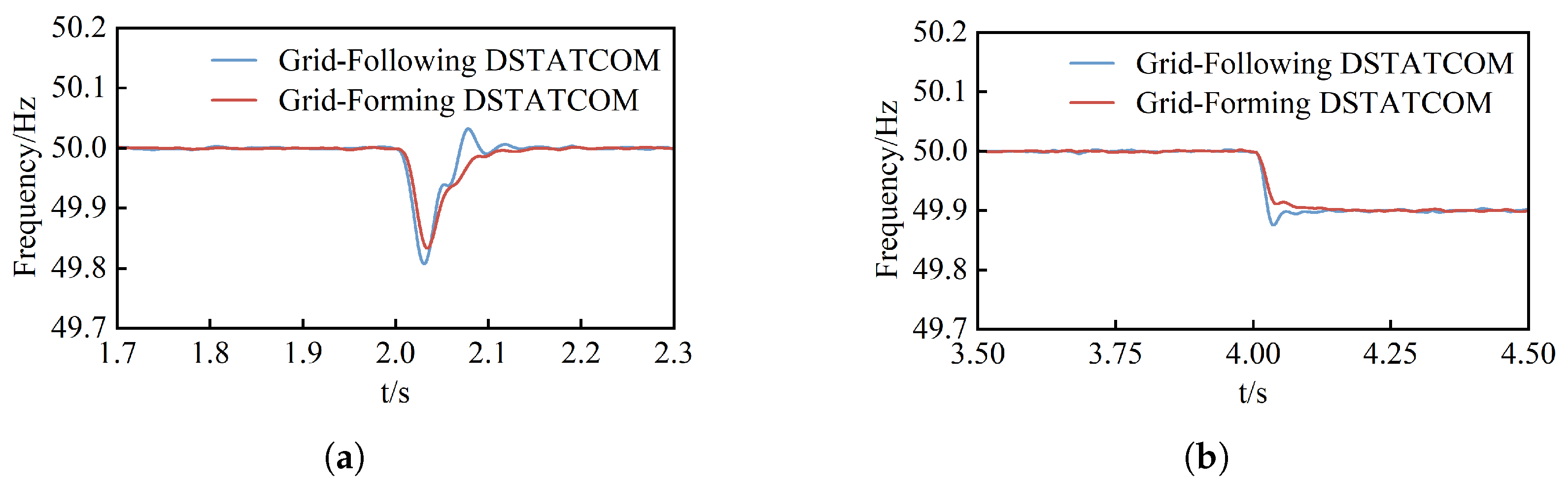
To verify the inertia support capability of the energy storage-type DSTATCOM under grid-forming control, two scenarios were set up: active power load disturbance and grid frequency drop.
Figure 14 shows the simulation results.
At
s, a constant power load
increased by 15 kW. The increase in load caused the system’s active power output to momentarily fall below the active power demand, leading to a decrease in system frequency. Under grid-following control, the system frequency dropped to a minimum of 49.83 Hz at
s; under grid-forming control, the minimum system frequency was approximately 49.87 Hz. Energy storage-type DSTATCOMs can provide some inertial support to the system by releasing energy from the storage batteries, mitigating the frequency fluctuations caused by load changes. At
s, a grid frequency fluctuation was introduced, causing a 0.1 Hz drop in grid frequency.
Figure 14b compares the frequency responses of the energy storage-type DSTATCOM under grid-following and grid-forming control modes. During grid frequency decline, the energy storage-type DSTATCOM can actively output active power to support frequency, slowing down the rate of frequency change. The magnitude of active power output is related to the output voltage frequency of the DSTATCOM and the grid frequency.
Figure 15a,b show the simulation results of a traditional DSTATCOM and the proposed grid-connected DSTATCOM under weak grid conditions.
Grid strength can be distinguished by the short circuit ratio (SCR), where , with being the short circuit capacity at the Point of Common Coupling (PCC) and being the rated capacity. Therefore, as the grid impedance increases, when the grid SCR is adjusted from 12 to 2.5, the traditional DSTATCOM exhibits a significant deterioration in grid current, while the proposed grid-type DSTATCOM maintains good current performance. In weak grid conditions, the proposed grid-type DSTATCOM exhibits superior stability compared to the traditional STATCOM, similar to the characteristics of a VSG. Conversely, the traditional DSTATCOM is prone to oscillations in weak grids, mirroring the behavior of conventional grid-connected inverters.
4.3. Simulation Verification of the Combined Control Effect of Power Quality and Active Voltage Support
To verify the effectiveness of energy storage-type DSTATCOM in improving power quality issues like harmonic and unbalanced currents in weak grids, the control effects of traditional grid-connected DSTATCOM and grid-forming DSTATCOM are compared.
Figure 16 shows the changes in grid-side current under different control modes of DSTATCOM in a weak grid.
Before the energy storage-type DSTATCOM was connected, the grid-side current showed significant distortion. As shown in
Figure 16b, the variation in the grid-side current under traditional grid-following control is presented. When the grid SCR is 12, the improved
compensation quantity detection algorithm introduced earlier can effectively mitigate the distorted current. At
s, by increasing the line impedance, the grid SCR is adjusted to 2.5. This results in a more significant harmonic distortion in the grid-side current.
Figure 16c shows the grid-side current changes under grid-forming control. When the grid SCR is adjusted to 2.5, the energy storage DSTATCOM effectively maintains the sinusoidal waveform of the grid-side current. This demonstrates that in weak grids, the energy storage DSTATCOM with grid-forming control has superior power quality regulation capabilities.
To further validate the strong anti-interference capability of the grid-forming controlled energy storage DSTATCOM in weak grids, a 5 kW active load surge was introduced in phase B at
s.
Figure 17 shows the resulting grid-side current changes. When a single-phase active load surge occurs in a weak grid, the grid-side current maintains a good sinusoidal shape without significant distortion. As shown in
Figure 17, the surge in the active load on phase B causes a three-phase current unbalance. The energy storage DSTATCOM detects this unbalance and generates compensating currents.
To verify the ability of energy storage-type DSTATCOM to achieve power quality improvement while possessing inertia and voltage support capabilities, the active power demand of the distribution network load is used as the active power reference value () for the energy storage-type DSTATCOM, and the reactive power reference value () is set to 0. The load side still consists of a 5 kW three-phase load and a single-phase uncontrolled rectifier circuit with inductance.
Figure 18 shows the voltage support effect of the energy storage-type DSTATCOM during a grid voltage dip. At
s, the grid voltage dips by
, and recovers at
s. The energy storage-type DSTATCOM maintains constant active power output, while increasing reactive power injection by 15 kVar.
Figure 18a,b demonstrate that the grid-connected energy storage-type DSTATCOM dynamically adjusts its power output based on voltage variations, providing excellent voltage support at the point of common coupling (PCC). The power change process is smooth and exhibits significant inertia.
This section’s simulation results demonstrate that the energy storage-type DSTATCOM in a grid-connected mode effectively manages power quality while simultaneously possessing inertia response and voltage support capabilities. Furthermore, it exhibits good anti-interference performance in weak grids.
4.4. Simulation Verification of Active and Reactive Power Coordinated Voltage Regulation in Grid-Connected Mode
Energy storage-type DSTATCOM, with the addition of energy storage batteries, creates conditions for active power compensation. Maintaining constant system and controller parameters, an 18 kW fixed load with a power factor of 0.9 is connected to the distribution feeder. Varying the simulation conditions, the simulation validates the active and reactive power coordinated voltage regulation method based on grid-connected mode.
The advantages of voltage regulation using active and reactive power coordinated control can be observed in the apparent power output of the energy storage-type DSTATCOM and the power flow in the upstream distribution network, as shown in
Figure 19.
Simulation settings with a line impedance ratio of 0.45 indicate that the optimal angle for voltage regulation efficiency of the energy storage-type DSTATCOM is 23.8°. At the start of the simulation, the energy storage-type DSTATCOM provides approximately 20 kVAR of reactive power to support the voltage. At s, a phase shift of 90° to 23.8° is applied, and at s, it returns to 90°. This result shows that after the transition to 23.8°, the energy storage DSTATCOM current output decreased, and upstream power flow also reduced. This demonstrates the advantage of controlled changes in the power factor angle. The reduced DSTATCOM power burden and upstream power flow are positive outcomes.
Figure 20 compares the output power of the energy storage DSTATCOM when the power factor angle and
ratio change. At the start of the simulation, the line impedance ratio
is set to 0.45, and an 18 kW resistive load is connected. Under these conditions, the optimal power factor angle
for the voltage regulation efficiency of the energy storage DSTATCOM is 23.8°.
Figure 20a shows that the voltage remains stable at 220 V regardless of the power factor angle. However, when
(pure reactive compensation), significant voltage fluctuations occur as the
ratio changes. Comparing
Figure 20b, we see that a power factor angle of 23.8° requires significantly less compensation capacity than 90°. This demonstrates the benefit of active power participation in voltage regulation. At
s, with
set to 1, the voltage sensitivity changes, and the optimal power factor angle for maximum voltage regulation efficiency is
. Observing the magnified area in
Figure 20b, we can see that flexibly adjusting the optimal power factor angle
based on the
ratio minimizes the required energy storage capacity of the DSTATCOM compensator.
Finally, simulation validation was performed on the voltage support effectiveness of the proposed method under voltage sag conditions.
Figure 21 shows the simulation results for different voltage regulation strategies under grid voltage sag conditions. At the beginning of the simulation, the energy storage-type DSTATCOM provides approximately 20 kVar of reactive power for voltage support through pure reactive compensation. At
s, a
voltage sag is introduced to the grid. The system then employs traditional VSG voltage regulation, pure active power regulation (
), pure reactive power regulation (
), and a coordinated active-reactive power regulation method based on the optimal power factor angle to adjust the PCC voltage to its setpoint. When the PCC phase voltage RMS value is raised to 220 V, the proposed grid-forming control strategy with coordinated active and reactive power regulation reduces the DSTATCOM capacity by 4000 VA compared to purely reactive power regulation, and by 12,800 VA compared to purely active power regulation. Under purely active power regulation, PCC voltage fluctuations are exacerbated, hindering system stability. Compared to traditional VSG control strategies, the proposed strategy exhibits significantly improved PCC voltage regulation effectiveness and superior voltage support capability, achieving similar apparent power compensation with a smaller DSTATCOM.
5. Experimental Results
To further validate the effectiveness of the improved
compensation algorithm and the active power-reactive power coordinated voltage regulation method proposed in this paper, a semi-physical simulation platform based on a dSPACE controller was built, as shown in
Figure 22. This platform features a three-phase four-bridge arm energy storage-type DSTATCOM. The three-phase four-bridge inverter main circuit constitutes the physical component, while the control circuit utilizes the dSPACE MicroLabBox, a controller developed by dSPACE GmbH. Due to limitations, offline closed-loop experiments were conducted. A three-phase sinusoidal voltage generator was used to emulate the grid voltage, and a DC power supply was employed to simulate the energy storage component. Key experimental parameters are presented in
Table 2.
First, the effectiveness of the improved
compensation algorithm and control strategy in filtering and compensating the negative-sequence double-frequency component is verified.
Figure 23 shows the three-phase unbalanced currents before compensation, as specified by the system.
Figure 24 shows a comparison of the
-axis double-frequency component filtering effects under different compensation methods. The figure demonstrates that the improved
compensation algorithm effectively filters the double-frequency AC components generated by negative-sequence components, compared to the traditional
compensation algorithm.
Figure 25 shows the
-axis current tracking performance under PI and PIR controllers. The traditional PI controller fails to achieve zero-steady-state error tracking of the twice-frequency current components; d-axis grid-connected current error is approximately 2 A, and q-axis error is approximately 2.5 A. In contrast, the PIR controller demonstrates excellent
-axis current tracking, with near-zero errors in both d and q axes. This indicates that the energy storage DSTATCOM effectively compensates for the twice-frequency components, aligning with the theoretical analysis.
Figure 26 shows the compensated three-phase current waveforms. Compared to the traditional
compensation algorithm, the improved
compensation algorithm results in three-phase waveforms that are balanced and essentially distortion-free.
Furthermore, the effectiveness of the active and reactive power coordinated voltage regulation method in grid-forming mode is validated.
Figure 25 shows the experimental results of the inertial response of the energy storage-type DSTATCOM in grid-forming mode. As seen in
Figure 27, when the reactive power reference value decreases from 3 kVar to 1 kVar, the output reactive power of the grid-forming DSTATCOM gradually follows the changing reactive power reference, exhibiting an inertial response similar to that of a synchronous generator due to the presence of the DSTATCOM’s rotational inertia.
In an off-grid closed-loop experiment, this paper verifies the inverter’s ability to flexibly adjust the output power factor angle and thereby achieve coordinated control of active and reactive power by controlling the angle between the inverter output current and the simulated grid voltage.
Figure 28 shows the experimental results when the active and reactive power distribution ratios are changed.
At the start of the experiment, the active power allocation was set to 0 and the reactive power allocation to 4 kVar, resulting in a simulated power factor angle
. At 11.1 s, the simulated power factor angle was changed to
, resulting in equal active and reactive power allocations, as shown in
Figure 28a. The inverter output the same active and reactive power.
Figure 28b shows the variation in the inverter’s apparent power. When active power compensation is considered, the inverter’s required compensation capacity decreases, reflecting the benefits of active power participation in voltage regulation.
Figure 28c,d show the phase relationships between the
A-phase voltage and current when changing the active and reactive power allocation ratios. Under pure reactive compensation, the phase difference between the
A-phase voltage and current is approximately 90°; under coordinated active and reactive compensation, the phase difference is approximately 45°. The results demonstrate that the inverter’s output power factor angle is flexible and controllable, indirectly validating the feasibility of the proposed strategy for voltage control.


