Abstract
In-band full-duplex (IBFD) technology has attracted significant attention for its potential to double the spectral efficiency by enabling a simultaneous transmission and reception over the same frequency channel. However, achieving high isolation between closely spaced transmit and receive paths remains a critical challenge. In this paper, a novel compact co-polarized monopole antenna with self-decoupling capability is proposed based on common-mode/differential-mode (CM/DM) theory. By innovatively folding the ends of the monopole elements, the antenna exploits the distinct behaviors under CM and DM excitations at a close spacing to achieve simultaneous impedance matching in both modes. This effectively enhances the isolation between antenna elements. The design enables self-interference suppression without requiring any additional decoupling structures, even under compact antenna and port spacing. Measurement results confirm that the proposed antenna achieves over 20 dB isolation within the 3.4–3.6 GHz operating band, with a compact spacing of 0.008 λ0 (λ0 corresponds to the wavelength at the center frequency).
1. Introduction
IBFD communication has emerged as a promising technique for doubling spectral efficiency by enabling simultaneous transmission and reception on the same frequency channel []. However, the main challenge is self-interference, which can be several orders of magnitude stronger than the desired signal. This issue is especially critical in co-polarized antenna systems, where strong electromagnetic coupling makes passive isolation inherently difficult. Tackling self-interference in such configurations is vital for the practical deployment of compact and efficient full-duplex radios.
To tackle this challenge, various techniques have been proposed in recent years. Specifically, antenna decoupling approaches can generally be categorized into three main types: coupling suppression, path cancelation, and mode cancelation.
The first category, coupling suppression, refers to methods that achieve decoupling by blocking the original electromagnetic coupling paths between antenna elements. One typical example is the use of electromagnetic bandgap (EBG) structures. In Ref. [], an EBG-based decoupling structure was inserted between patch elements to suppress inter-element coupling without affecting the beamwidth of the antenna array, achieving 27 dB isolation at a spacing of 0.608 λ0, where λ0 refers to the free-space wavelength at the center frequency. However, such EBG structures often require large inter-element spacing and introduce complex design and fabrication challenges. Another widely used approach is the defective ground structure (DGS). In Ref. [], a DGS composed of complementary split-ring resonators was proposed to suppress the surface wave propagation across a wide frequency range, achieving a 10 dB improvement in isolation at a spacing of 0.25 λ0. While this approach maintains the radiation characteristics of the individual antenna elements, it also increases the system footprint due to the need for a ground-level decoupling area.
The second approach introduces a cancelation path to neutralize the coupling effect, utilizing elements such as neutralization lines [], decoupling networks [], or decoupling surfaces []. In Ref. [], a neutralization line was inserted between antenna elements to create a secondary coupling path that counteracts the original one, achieving over 20 dB isolation with an inter-element spacing of 0.23 λ0. In Ref. [], a decoupling network based on a Wilkinson power divider was employed, enabling 20 dB isolation over a 23.7% relative bandwidth at only 0.1 λ0 edge-to-edge spacing. Although such approaches are effective, the decoupling networks themselves are often complex and require additional layout space, which increases the overall size of the antenna system. In Ref. [], a decoupling surface composed of small metallic patches was placed above the antennas to create a compensating radiation path, yielding 24 dB isolation at 0.45 λ0 spacing. While this technique is structurally independent from the main antenna array, it adds vertical complexity and increases the overall size.
In recent years, several decoupling methods based on the mode analysis of antennas have been proposed, which achieve decoupling by leveraging mode cancelation [,]. In Ref. [], the high-order TE113 mode of a dielectric resonator antenna (DRA) was utilized, taking advantage of its unique ability to be excited by the DRA body but not by the feed network. This modal selectivity allowed for 20 dB of isolation without increasing the structural complexity. However, the design needed a relatively large element spacing of 0.484 λ0 and heavily depended on the specific modal properties of the DRA, which limited its broad application. Later, Ref. [] introduced a decoupling technique based on CM/DM modal decomposition, transforming the decoupling challenge into a matching problem between two orthogonal modes. This offered a simpler, physically intuitive approach for analyzing and designing decoupled antenna systems. Building on this concept, a full-duplex dipole antenna was further developed in which the CM and DM modes were independently tuned using structural branches and lumped capacitors. The antenna achieved 20 dB of isolation at an element spacing of 0.2 λ0. Although this method enhances design efficiency through separate modal control, it still requires additional decoupling components, which increases the structural complexity and may limit its use in compact or highly integrated systems.
This paper introduces a novel compact co-polarized full-duplex monopole antenna based on CM/DM mode decoupling. By innovatively utilizing the CM and DM behavior of closely spaced monopole elements, the ends of the monopoles are bent to create a dipole DM resonance without affecting the original CM resonance. The physical mechanism and decoupling principle of this mode are explained in detail. Parametric studies further confirm the feasibility of independently matching CM and DM modes. Measurement results show that the proposed antenna achieves effective self-decoupling without additional decoupling components, even with compact antenna and port spacing. Additionally, the antenna has a simple structure and clear design principle, allowing for more efficient design iterations.
2. Antenna Design Principles
2.1. CM and DM Theory
CM and DM signals are defined in a two-port system as excitations with equal amplitudes but differing phase relationships—in-phase for the CM and out-of-phase for the DM. In a reciprocal two-port network, the scattering parameters satisfy the condition . Furthermore, if the system is also symmetric, then holds as well. According to microwave network theory, for a reciprocal and symmetric two-port system, the relationships between the conventional S-parameters and the CM/DM S-parameters can be expressed as Ref. []
By solving the above two equations simultaneously, we obtain
From these equations, it is evident that to achieve the perfect isolation between ports such that , it is necessary to satisfy the condition . This implies that the system must achieve equal levels of impedance matching under both CM and DM operations. Specifically, when , it follows that , indicating that impedance matching is achieved at both antenna ports. In conclusion, from the perspective of CM/DM theory, the fundamental requirement for antenna decoupling is to achieve impedance matching under both operating modes simultaneously.
2.2. The Basic Structure and Analysis of the Antenna
To demonstrate the implementation of the proposed self-decoupling mechanism based on the above CM/DM theory, this section compares the operating principles of a conventional compact monopole antenna pair and the proposed end-bent design, outlining the design evolution and underlying physical mechanisms.
As shown in Figure 1, the proposed design introduces a structural modification by bending the ends of the monopole arms to facilitate both the CM and DM impedance matching. For clarity, the antenna spacing is depicted as relatively large in the figure; however, in practice, the spacing satisfies . To demonstrate the effect of this bending, Figure 2 illustrates the CM and DM current distributions of conventional monopole antennas placed close without bending. Figure 2a displays the current distribution and equivalent structure when the antenna operates in the CM. It can be seen that, under the CM excitation, two closely spaced monopole antennas are effectively equivalent to a single monopole antenna with the same height but double the width. The reason the gap between antennas can be neglected under the CM excitation is that, in a symmetric two-port system, the symmetry plane behaves as an open circuit for common-mode signals. Therefore, when the antenna spacing d is sufficiently small, the system’s behavior remains effectively unchanged. Figure 2b shows the operational state under the DM excitation. In this case, the antenna system is effectively modeled as a pair of parallel transmission lines with open ends. According to transmission line theory, an open-ended line results in total reflection, preventing impedance matching. As a result, conventional monopole antennas fail to resonate under DM excitation and cannot achieve port-to-port isolation.
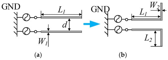
Figure 1.
The evolution process of the proposed antenna. (a) Conventional antenna and (b) proposed antenna (L1 = 33.5 mm, L2 = 18.6 mm, W1 = 0.6 mm, W2 = 2 mm, and d = 0.7 mm).
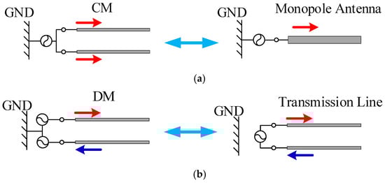
Figure 2.
Equivalent CM/DM models and current distributions of the compact monopole antenna pair: (a) CM and (b) DM.
Figure 3 illustrates the operating mechanisms of the proposed antenna under CM and DM excitations. Compared with the conventional design, the proposed antenna incorporates bent terminations at the ends of the two monopole elements. Under the CM excitation, as shown in Figure 3a, the antenna behaves similarly to the traditional structure and can be equivalently modeled as an inverted-L monopole with outward-bent ends. In contrast, under the DM excitation, as shown in Figure 3b, the segment before the bend still resembles a pair of parallel transmission lines, much like in conventional designs. However, the bent sections act as a dipole fed by parallel lines. In this configuration, the antenna is no longer in a state of total reflection, and impedance matching becomes achievable. This behavior highlights the potential of the proposed structure to realize self-decoupling.
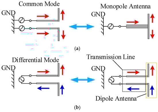
Figure 3.
Equivalent CM/DM models and current distributions of the proposed antenna pair: (a) CM and (b) DM.
To validate the aforementioned conclusions, Figure 4 presents the CM and DM S-parameter curves for both the conventional and the proposed end-bent monopole antennas. Figure 4a shows the S-parameter curves of the conventional monopole antenna without end bending. As observed, and consistent with the theoretical analysis, when the monopole arm length L1 increases from 38 mm to 58 mm, a clear resonance occurs under the CM excitation, with the resonant frequency decreasing from 4.31 GHz to 2.92 GHz. However, under DM excitation, no resonance is observed across the entire frequency band, and the antenna remains in a state of total reflection. This is because the conventional compact monopole antenna behaves as a resonant monopole under the CM excitation, whereas under the DM excitation, it is equivalent to an open-ended transmission line, which inherently cannot resonate. In contrast, Figure 4b shows the S-parameter curves of the proposed end-bent monopole antenna. As can be seen, when the bent length L2 increases from 12 mm to 14 mm, the antenna still exhibits resonance in the CM, with only a slight shift in the resonant frequency. More importantly, unlike the conventional monopole, resonance also occurs under the DM excitation. Specifically, as L2 increases from 12 mm to 14 mm, the DM resonant frequency shifts from 4.27 GHz to 4.03 GHz. This is because, in the CM mode, the end-bent monopole is equivalent to a T-shaped monopole antenna whose resonant frequency is governed by the overall length. In contrast, under the DM excitation, the structure behaves like a dipole antenna, and its resonant frequency is primarily determined by the bent section length. The emergence of the DM resonance in the proposed antenna—replacing the total reflection observed in the conventional design—demonstrates its potential to achieve simultaneous impedance matching under both the CM and DM excitation.
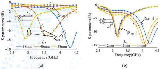
Figure 4.
CM and DM S-parameter curves of the antenna under different parameters: (a) conventional antenna, L1, and (b) proposed antenna, L2.
2.3. The CM/DM Analysis of the Antenna
This section provides a detailed analysis of the operational behavior of the end-bent antenna and presents a method for achieving simultaneous CM and DM matching. For the end-bent antenna shown in Figure 1b, based on the analysis framework of monopole antennas, the resonant frequencies under both CM and DM excitations are expressed as
where denotes the speed of light in a vacuum, while and represent the order CM and order DM resonant frequencies of the antenna, respectively, with . and corresponding to the lengths of the unbent and bent sections of the antenna, respectively. When the antenna system is required to operate at the same frequency in both the CM and DM, the condition must be satisfied, leading to the following relationship:
Given that and , it follows from Equation (6) that must hold. Since both and are odd integers, and in order to minimize the physical size of the antenna, a straightforward solution that minimizes the antenna size is and . Under this condition, the antenna operates in the third-order mode as a monopole in the CM, and in the first-order mode as a dipole in the DM.
To intuitively illustrate the physical significance of the above analysis, Figure 5 shows the current distributions of the antenna operating in the first- and third-order modes under both CM and DM excitations. Figure 5a,b depict the cases where both the CM and DM operate in the first-order mode. Clearly, since in this case, the antenna in the common mode is equivalent to a monopole operating in the first-order mode, whereas the equivalent dipole in the DM at this frequency cannot resonate. Figure 5c,d show the current distributions when and . It is evident that under these conditions, the antenna resonates as a third-order monopole in the CM and as a first-order dipole in the DM. Both modes can achieve resonance simultaneously.
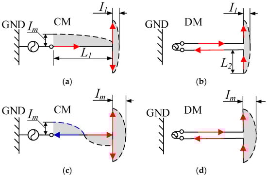
Figure 5.
Current distributions of the proposed antenna at the fundamental and third-order modes: (a) CM, fundamental; (b) DM, fundamental; (c) CM, third-order; and (d) DM, third-order.
To validate the above conclusion, the antenna shown in Figure 1b was simulated using HFSS to investigate how various structural parameters affect its CM and DM resonances. Figure 6 illustrates how the parameters and vary with changes in . Specifically, Figure 6a presents the S-parameter values in decibels using a rectangular plot, while Figure 6b shows the corresponding curves on a Smith chart. From the figures, it can be observed that as increases from 34 mm to 37 mm, the resonant frequency of shifts from 3.65 GHz down to 3.37 GHz, and its return loss initially improves from −25 dB to −45 dB and then degrades to −29 dB. In contrast, exhibits only a minor shift, decreasing from 3.58 GHz to 3.45 GHz, with little variation in the return loss. These results are consistent with the analysis based on Equations (4) and (5). The DM reflection coefficient is less sensitive to changes in , because in the DM operation, the portion of the antenna represented by can be modeled as a pair of parallel transmission lines, which contribute little to the resonant behavior. On the other hand, the CM reflection coefficient is strongly affected by , since under the CM excitation, the portion of the antenna before the bend forms part of the resonant monopole. As a result, variations in significantly influence the CM resonant frequency. Furthermore, because the antenna behaves as a T-shaped monopole in the CM, changes in also alter the degree of bending, thereby affecting the impedance matching under the CM operation.
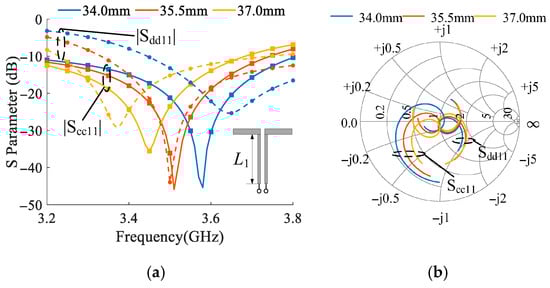
Figure 6.
The influence of the parameter L1 on the CM/DM S-parameters of the antenna. (a) The rectangular plot and (b) the Smith chart.
Figure 7 shows the variation in the antenna’s S-parameters as a function of . As shown in Figure 7a, the DM parameter is significantly influenced by changes in . When increases from 17 mm to 20 mm, the resonant frequency of shifts from 3.65 GHz down to 3.37 GHz, whereas the resonant frequency of only shifts slightly, from 3.56 GHz to 3.47 GHz. This trend is also clearly visible in the Smith chart of Figure 7b, where demonstrates a greater sensitivity to changes in . This behavior can be attributed to the fact that, under the DM operation, the bent segment of the antenna can be regarded as a dipole with an arm length of , so variations in directly influence the resonant frequency in this mode. Similarly, since the bent section also constitutes a part of the resonant structure under the CM operation, is also affected by changes in . However, it is important to note that the antenna resonates in the third-order mode under the CM excitation and in the fundamental mode under the DM excitation. Consequently, the resonance shift observed in is slightly more pronounced.
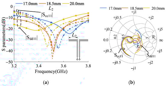
Figure 7.
The influence of the parameter L2 on the CM/DM S-parameters of the antenna. (a) The rectangular plot and the (b) Smith chart.
The above analysis focuses on how various antenna parameters affect the resonant frequencies. However, according to the CM/DM theory, an antenna system must not only exhibit the same resonant frequency in both modes but also achieve proper impedance matching in both. To meet this requirement, the parameter can be adjusted. To demonstrate this, Figure 8 illustrates the variation in the antenna’s S-parameters with changes in . As shown, when increases from 1.5 mm to 2.5 mm, the resonant frequency of the DM remains nearly unchanged. However, the return loss improves significantly, dropping from −24 dB to −46 dB, before rising again to −25 dB. Meanwhile, the CM resonant frequency slightly increases from 3.45 GHz to 3.55 GHz, with almost no change in the return loss. Notably, the Smith chart clearly reveals that has a minimal influence on the resonant frequency but plays a significant role in tuning the impedance matching level of the DM. This highlights the effectiveness of in fine-tuning the CM/DM matching performance without shifting the resonant frequency.
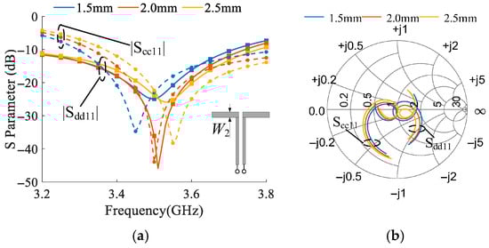
Figure 8.
The influence of the parameter W2 on the CM/DM S-parameters of the antenna. (a) The rectangular plot and the (b) Smith chart.
Based on the above analysis, a clear antenna design guideline can be proposed. First, the initial values of the antenna’s geometric parameters can be estimated using Equations (4) and (5) for the desired operating frequency. Next, the resonant frequencies of the CM and DM can be fine-tuned by leveraging the differing sensitivities of parameters and . Finally, the parameter can be used to optimize the impedance matching of both modes at the target resonant frequency.
Moreover, the proposed end-bent structure introduces a dipole resonance mode under a non-resonant DM condition. The further theoretical analysis shows that when the compact monopole operates in a third-order CM resonance, adjusting structural parameters can bring the DM dipole resonance to its fundamental mode. This enables simultaneous CM/DM matching and, as a result, achieves self-decoupling under compact spacing without adding structural complexity.
3. Experimental Verification and Discussion
To validate the proposed design methodology, an antenna operating at 3.5 GHz was designed, fabricated, and measured. The basic structure of the antenna is shown in Figure 9, and the fabricated prototype along with the measurement setup is depicted in Figure 10. A realistic model of the SMA connector is included in the full-wave simulation to ensure that the results accurately reflect the actual port performance. All measurements were conducted using a commercial test system within an anechoic chamber. The antenna under investigation was placed in the quiet zone, and standard calibration procedures were performed to ensure measurement accuracy. A Rohde & Schwarz ZVA24 vector network analyzer, manufactured by Rohde & Schwarz, based in Munich, Germany, was used to capture the S-parameters. The dimensions of the anechoic chamber are 1.75 m × 1.675 m × 2.03 m. The proposed antenna is built on a single-layer FR4 substrate with a thickness of 1.2 mm, a relative permittivity of εr = 4.4, and a loss tangent of tan δ = 0.02. The antenna structure is compact and simple. Compared to conventional monopole antennas, the proposed design features two closely spaced, end-bent monopole elements, with both inter-element and port-to-port spacing as small as 0.008 λ0. The top layer includes the monopole radiators and feeding microstrip lines, while the bottom layer contains a truncated ground plane. The final optimized geometrical parameters are summarized in Table 1.
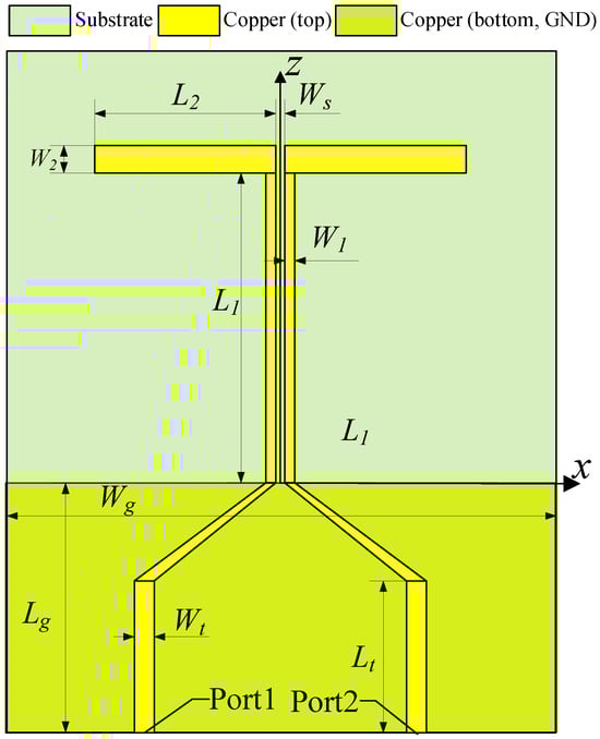
Figure 9.
The structure of the proposed antenna.
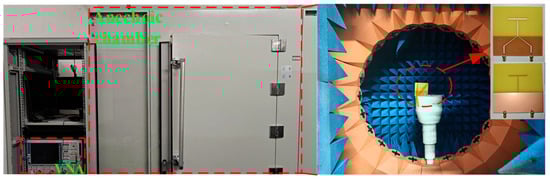
Figure 10.
Fabricated antenna and measurement environment.

Table 1.
Structural parameters of the antenna.
Figure 11 presents both the simulated and measured S-parameters of the proposed antenna. As shown, the measured results agree well with the simulations. The antenna achieves good impedance matching over a wide frequency range from 2.8 GHz to 4.5 GHz, with remaining below −10 dB. Moreover, the isolation parameter exceeds 20 dB within the target 3.4–3.6 GHz band and reaches a maximum value of 48 dB at 3.46 GHz. These results confirm that the proposed folded-end monopole antenna achieves high isolation without employing any additional decoupling structures. This strongly validates the effectiveness of the self-decoupling mechanism based on the CM/DM theory. Figure 12 shows the radiation patterns at the resonant frequency under the excitation from port 1, demonstrating a close agreement between the measurement and simulation. Minor discrepancies are likely due to assembly tolerances.
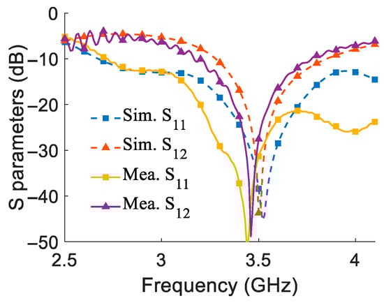
Figure 11.
Simulated and measured S-parameters of the proposed antenna.
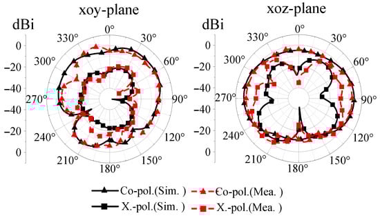
Figure 12.
The radiation pattern of the antenna.
To intuitively demonstrate the decoupling performance of the folded monopole antenna, Figure 13 illustrates the surface current distribution at the resonant frequency of 3.5 GHz when the antenna is excited from port 1. It is evident that the feedline of port 2 carries a negligible current, indicating that effective self-decoupling is achieved even with an compact port spacing of 0.008 λ0.
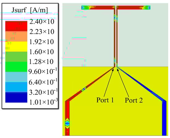
Figure 13.
The surface current distribution of the antenna at 3.5 GHz.
To highlight the advantages and contributions of the proposed antenna, Table 2 presents a performance comparison with representative prior works. As discussed in the Introduction, many conventional decoupling techniques rely on additional structures such as DGSs [] or decoupling networks [,,], which increase the overall system complexity and enlarge the antenna footprint. Although some recent works [,] adopt self-decoupled designs that eliminate external structures and reduce the system complexity, they still require a relatively large element and port spacing. In contrast, the proposed antenna takes advantage of the inherent compactness of monopole elements to achieve self-decoupling. It enables both the element and port spacing to be simultaneously compact while maintaining a simple structure and clear design principle. This allows for a more efficient and straightforward design process. However, due to the extremely small element spacing, the proposed design makes a trade-off in terms of the impedance bandwidth compared to the design [], as reflected in the comparison.
Table 2.
Comparison with reported antennas.
4. Conclusions
A compact full-duplex monopole antenna based on CM/DM theory is proposed. The CM and DM characteristics of closely spaced monopole antenna pairs are analyzed, and a method for achieving DM impedance matching via end bending is presented. A detailed parametric study is conducted to investigate the relationship between the antenna’s structural dimensions and its CM/DM S-parameters, based on which a systematic antenna design and tuning method is established. A prototype antenna is then fabricated and experimentally validated. Measurement results demonstrate that the antenna achieves over 20 dB isolation within the 3.4–3.6 GHz frequency band, with an antenna and port spacing as small as 0.008 λ0. This self-decoupled antenna leverages the intrinsic DM characteristics of compact monopole structures, resulting in a significantly reduced footprint compared to previous designs. Moreover, its structurally simple configuration enables the independent tuning of the CM and DM responses by adjusting specific geometric parameters, thereby simplifying the iterative optimization process. These features make the proposed design particularly suitable for full-duplex and MIMO applications.
Author Contributions
Conceptualization, Y.L. (Yuejian Li) and Y.L. (Yu Luo); methodology, Y.L. (Yuejian Li) and Y.L. (Yu Luo); software, Y.L. (Yuejian Li); validation, Y.L. (Yuejian Li); formal analysis, Y.L. (Yuejian Li); investigation, Y.L. (Yuejian Li); resources, Y.L. (Yu Luo); data curation, Y.L. (Yuejian Li); writing—original draft preparation, Y.L. (Yuejian Li); writing—review and editing, Y.L. (Yuejian Li), Y.H. and Y.L. (Yu Luo); visualization, Y.L. (Yuejian Li); supervision, Y.L. (Yu Luo) and Y.H.; project administration, Y.L. (Yu Luo); funding acquisition, Y.L. (Yu Luo) All authors have read and agreed to the published version of the manuscript.
Funding
This research was supported in part by the National Natural Science Foundation of China (62101380).
Data Availability Statement
All data supporting the reported results are included in the article.
Conflicts of Interest
The authors declare no conflicts of interest.
References
- Kolodziej, K.E.; Perry, B.T.; Herd, J.S. In-Band Full-Duplex Technology: Techniques and Systems Survey. IEEE Trans. Microwave Theory Techn. 2019, 67, 3025–3041. [Google Scholar] [CrossRef]
- Vilenskiy, A.R.; Litun, V.I.; Lyulyukin, K.V. Wideband Beam Steering Antenna Array of Printed Cavity-Backed Elements With Integrated EBG Structure. IEEE Antennas Wirel. Propag. Lett. 2019, 18, 245–249. [Google Scholar] [CrossRef]
- Bait-Suwailam, M.M.; Siddiqui, O.F.; Ramahi, O.M. Mutual Coupling Reduction between Microstrip Patch Antennas Using Slotted-Complementary Split-Ring Resonators. IEEE Antennas Wirel. Propag. Lett. 2010, 9, 876–878. [Google Scholar] [CrossRef]
- Zhang, S.; Pedersen, G.F. Mutual Coupling Reduction for UWB MIMO Antennas with a Wideband Neutralization Line. IEEE Antennas Wirel. Propag. Lett. 2016, 15, 166–169. [Google Scholar] [CrossRef]
- Li, M.; Jiang, L.; Yeung, K.L. A Novel Wideband Decoupling Network for Two Antennas Based on the Wilkinson Power Divider. IEEE Trans. Antennas Propag. 2020, 68, 5082–5094. [Google Scholar] [CrossRef]
- Wu, K.-L.; Wei, C.; Mei, X.; Zhang, Z.-Y. Array-Antenna Decoupling Surface. IEEE Trans. Antennas Propag. 2017, 65, 6728–6738. [Google Scholar] [CrossRef]
- Pan, Y.M.; Hu, Y.; Zheng, S.Y. Design of Low Mutual Coupling Dielectric Resonator Antennas Without Using Extra Decoupling Element. IEEE Trans. Antennas Propag. 2021, 69, 7377–7385. [Google Scholar] [CrossRef]
- Sun, L.; Li, Y.; Zhang, Z.; Wang, H. Antenna Decoupling by Common and Differential Modes Cancellation. IEEE Trans. Antennas Propag. 2021, 69, 672–682. [Google Scholar] [CrossRef]
- Zhang, A.; Wei, K.; Guan, Q.; Hu, Y. Compactly Placed High-Isolated Antenna Pair With Independent Control of Decoupling Amplitude and Phase. IEEE Trans. Antennas Propag. 2023, 71, 2814–2819. [Google Scholar] [CrossRef]
- Cao, Z.; Chang, L.; Li, Y.; Wei, K.; Zhang, Z. Decoupling of Axial Symmetric Three Antennas Based on Active Impedance Matching. IEEE Trans. Antennas Propag. 2024, 72, 6919–6929. [Google Scholar] [CrossRef]
- Zhou, Z.; Cheng, Z.; Zhang, Z.; Ge, Y.; Chen, Z. Visualized Design of Antenna Decoupling Networks Constructed by Cascaded Coupled Lines. IEEE Trans. Antennas Propag. 2024, 72, 4744–4753. [Google Scholar] [CrossRef]
- Xu, Z.; Deng, C. High-Isolated MIMO Antenna Design Based on Pattern Diversity for 5G Mobile Terminals. Antennas Wirel. Propag. Lett. 2020, 19, 467–471. [Google Scholar] [CrossRef]
Disclaimer/Publisher’s Note: The statements, opinions and data contained in all publications are solely those of the individual author(s) and contributor(s) and not of MDPI and/or the editor(s). MDPI and/or the editor(s) disclaim responsibility for any injury to people or property resulting from any ideas, methods, instructions or products referred to in the content. |
© 2025 by the authors. Licensee MDPI, Basel, Switzerland. This article is an open access article distributed under the terms and conditions of the Creative Commons Attribution (CC BY) license (https://creativecommons.org/licenses/by/4.0/).