Article

Autonomous Textile Sorting Facility and Digital Twin Utilizing an AI-Reinforced Collaborative Robot

by
Torbjørn Seim Halvorsen
,
Ilya Tyapin
and
Ajit Jha
*
Department of Engineering Sciences, University of Agder, 4879 Grimstad, Norway
*
Author to whom correspondence should be addressed.
Electronics 2025, 14(13), 2706; https://doi.org/10.3390/electronics14132706
Submission received: 6 May 2025 / Revised: 17 June 2025 / Accepted: 19 June 2025 / Published: 4 July 2025
(This article belongs to the Special Issue New Insights Into Smart and Intelligent Sensors)

Abstract

This paper presents the design and implementation of an autonomous robotic facility for textile sorting and recycling, leveraging advanced computer vision and machine learning technologies. The system enables real-time textile classification, localization, and sorting on a dynamically moving conveyor belt. A custom-designed pneumatic gripper is developed for versatile textile handling, optimizing autonomous picking and placing operations. Additionally, digital simulation techniques are utilized to refine robotic motion and enhance overall system reliability before real-world deployment. The multi-threaded architecture facilitates the concurrent and efficient execution of textile classification, robotic manipulation, and conveyor belt operations. Key contributions include (a) dynamic and real-time textile detection and localization, (b) the development and integration of a specialized robotic gripper, (c) real-time autonomous robotic picking from a moving conveyor, and (d) scalability in sorting operations for recycling automation across various industry scales. The system progressively incorporates enhancements, such as queuing management for continuous operation and multi-thread optimization. Advanced material detection techniques are also integrated to ensure compliance with the stringent performance requirements of industrial recycling applications.

1. Introduction

Waste management is critical to reduce pollutants, minimize environmental impact, and achieve sustainable development goals. A circular economy includes municipal solid waste systems as described by Sondh et al. [1], construction and demolition waste management by Ma et al. [2], end-of-life vehicle recycling by Molla et al. [3], domestic food waste strategies by Angelo et al. [4], and electronic waste recycling technologies by Mishra et al. [5]. Among the several areas that require waste management, textile waste management in terms of reduce, recycle, reuse (3Rs) has gained significant attention from Voukkali et al. [6]. Similarly, Papamichael et al. concluded that the fashion industries are one of the most polluting industries in the world [7]. Regarding the change in consumer behavior, “ready-to-wear” and “use–dispose” fast fashion has caused about a 40% reduction in the life time of textiles. De Ponte et al. stated [8] that the fashion industry emits 5000 million tons of CO2 annually, accounting for 9% of global emissions. It also contributes to over a third of marine microplastic pollution and 20% of industrial wastewater contamination. The industry consumes 98 million tons of non-renewable resources, 93 billion cubic meters of water, and over 70 million barrels of oil. In 2017, the European Union (EU) alone used 1.3 tons of raw materials and 104 cubic meters of water, generating 654 kg of CO2 emissions per person. Between 2000 and 2014, over 140 billion garments were produced while the EU discards 1 million tons of textiles annually. Of these discarded textiles, only 1% are reused, 12% are recycled, and the rest are burnt or landfilled as written by Papamichael et al. [9]. In this regard, Chioatto S.P. on behalf of the European Union has identified and proposed a road map [10] to identify the solutions to waste management. The New Circular Economy Action Plan—For a Cleaner and More Competitive Europe highlights the textile industry as key to the circular economy transition. It aims to save resources and enhance recycling by standardizing waste collection across the EU and improving textile sorting and recycling.

2. Related Work

Post-consumer textile waste requires sorting them based on color, material, chemical composition, size, and qualities. Textile waste is currently manually sorted, which is cost-effective in developing countries with low labor costs and allows for quality estimation, especially regarding reusability. However, manual sorting is time-consuming, inefficient for large volumes, and unable to separate waste based on chemical composition without relying on potentially faulty or missing product labels. In addition, workers often face poor working conditions, leading to inconsistent sorting outcomes. To overcome these limitations, automated textile sorting is being developed to sort the textiles based on material, chemical composition, and colors.
In this regard, Bianchi et al. used radio frequency identification (RFID) tags to sort the textiles [11]. RFID tags can store product information such as chemical composition, color, and age, which can be read remotely by sensors in sorting facilities. However, these tags are primarily used for clothing and often malfunction after several laundry cycles. Riba et al. implemented approaches based on near-infrared spectroscopy (NIR) to classify textiles based on material [12]. Extending the spectral band and resolution, Bonifazi et al. [13] used hyperspectral imaging (HSI) to detect the plastic in textiles, with different types of material forming textile and polymers. The disadvantages of HSI is that it is computationally expensive and requires specific lighting conditions and calibration. Similarly, Tsai and Yuan [14] used Raman spectroscopy together with machine learning (ML) models such as Principal Component Analysis (PCA), K-Nearest Neighbor (KNN), Support Vector Machine (SVM), Random Forest (RF), Artificial Neural Networks (ANNs), and Convolution Neural Networks (CNNs) to detect the material of the textile for sorting.
Image-based textile identification leveraging an ML algorithm was also demonstrated by Miao et al. [15]. Their approach is based on the feature fusion-based re-ranking method for home textile image retrieval. Image-based analysis of textile fabric for evaluating homogeneity within and between weave repeats in fabric structures (termed as intra-repeat (IAR) and inter-repeat (IER)) assessment was shown by Owczarek [16]. The implication of this is to address local changes in the fabric structure.
In addition to textile material detection, textile recycling involves four primary methods, chemical, thermal, biological, and mechanical, as described by Behera et al. [17]. Chemical recycling of polymers involves breaking down fibers through depolymerization or dissolution. Chemical recycling methods for polyesters discussed by Papamichael et al. include glycolysis, methanolysis, and hydrolysis [9]. Chemical recycling yields higher-value products, like transparent films, construction materials, and synthetic fibers. However, challenges include high chemical and water consumption high costs, complex processing, and significant energy demands. Selective degradation is more suitable for large-scale recycling of blended fabrics. Biological treatment through biodegradation presented by Wojnowska-Baryła et al. and Araye et al. involves microorganisms, such as bacteria and fungi, breaking down textile waste [18,19]. The disadvantages with this approach are that it is a slow process and different materials require different microbes to break them down. Similarly, mechanical treatment involves two main processes: waste sorting and mechanical decomposition. Sorting distinguishes fibers based on type, color, quality, and other physical properties. Decomposition, typically through shredding, breaks textiles into a fibrous form, making it the most common method for mechanical textile recycling. The advantages with mechanical sorting is that it reduces the chemical waste and does not require extreme environments.
In an era where automation and machinery are more common in various industries, the recycling sector faces a demand for change. So far, wide research is conducted only on detection or material classification. Not much work is conducted on color detection/classification. Color classification is another important aspect of textile sorting that has to be taken into consideration. For example, white textiles are heavily used in hospitals. To rechannel and reuse the textiles based on colors is an attractive way of “goal-specific” sorting. Further, the end-to-end development of a recycling/sorting facility includes sensors, hardware, software, and system integration. Regarding technological integration into industrial systems, there has been a noticeable growth in the evolution of Artificial Intelligence (AI). Significant attention is being paid to advancing computer vision (CV), ML, and robotics to drive systems toward autonomy. These technologies allow machines and robots to perceive and interact with their surroundings. This transformation is necessary for the concept of Industry 4.0, that is, integrating the Industrial Internet of Things (IIoT), which is seen to revolutionize production lines and other sectors by enhancing productivity, communication, and efficiency. The ongoing development in various industries, including textile recycling, indicates a significant paradigm shift. The implementation of autonomous sorting operation on a moving conveyor belt presents a challenging task.
When using autonomous robotic operations, the entire stack can be divided into three sections—(a) perception, computer vision, and machine learning; (b) robotic manipulation; and (c) system integration. Perception is the choice of sensors together with the algorithm to make meaningful information from the sensor data. Its typically a Red–Green–Blue (RGB) camera that captures light in red, green, and blue wavelengths and produces colored images. RGB cameras are increasingly utilized in pick-and-place operations for autonomous operations. These 2D cameras capture high-resolution color images that enable robots to identify and localize objects precisely, which is essential for manipulation. Moreover, integrating RGB-depth cameras provides color and spatial information, allowing robots to gauge the distance and form of objects more accurately. This capability, discussed by Khan et al. and Sahba et al., is particularly beneficial for complex scenarios where depth perception is crucial for successful interaction with surrounding objects [20,21]. Similarly, Zhichao et al. [22] proposed a light-weight ML framework—EPRepSADet—to detect foreign objects. Further, in [23], a framework was proposed based on neural radiance fields to navigate in complex environments autonomously.
The basic abilities of robotic manipulators are picking up, holding, and placing objects. Grippers, which can be associated with hands, are the tools at the end of the robot’s arm. Securely grasping an object involves making contact with the object and minimizing the risk of potential slippage or damage during the pick-and-place process. Zhang et al. proposed the use of various sensors and control strategies to ensure secure grasping of a wide range of objects differing in shape and size [24]. Samadikhoshkho et al. [25] noted that a seemingly simple task—grasping an object—can become unexpectedly complex when determining the optimal gripping strategy. Often, there is a need for a custom gripper, such as a vacuum, finger gripper, claw gripper, or one that is electric or pneumatic. A growing trend in gripper technology is the use of pneumatic grippers, which provide flexibility and adjustability in holding objects, allowing for the gentle and versatile handling of fragile items. Fenjan and Dehkordi [26] investigated the design of molds for silicone fingers incorporating built-in air chambers. This design allows for bending movements even with minimal pneumatic pressure, facilitating secure and adaptable grasping while minimizing the risk of damage. Ji et al. [27] pointed out that this novel technology has its own set of challenges because of its intrinsic structural limitations that result in stability deficiencies when compared to rigid grippers. They developed a hybrid flexible robotic gripper (FRG) mechanism that combines a flexible vertebra-type mechanism and a rigid link in order to solve this problem. Similarly, Ariyanto et al. [28] created a gentle three-finger robotic gripper that uses positive or negative pressure to grasp objects. Heikkilä et al. [29] and Spyridis et al. [30] demonstrated that integrating robotic manipulators with conveyor systems significantly enhances both efficiency and accuracy in industrial recycling processes.
Robotic manipulation systems combined with conveyor belts have been extensively studied for sorting tasks. Luo et al. [31] demonstrated a robotic system integrating RGB-D cameras to enable deep learning-based autonomous grasping from conveyor belts, significantly improving efficiency and reliability in logistics and industrial settings. Similarly, Morrison et al. [32] presented an advanced pick-and-place robotic sorting application for recyclable objects, leveraging neural network-driven RGB-D camera perception and robotic arms to handle cluttered environments effectively. The research on a modular conveyor belt system integrated with robotic sorting highlights the benefits of modularity and adaptability, emphasizing enhanced accuracy and scalability in sorting diverse materials, including textiles [33]. Similarly, Heikkilä et al. [29] explored the automated sorting of textiles using NIR spectroscopy combined with conveyor belt systems, demonstrating high accuracy in fiber-type classification, which is essential for effective recycling processes. Finally, Spyridis et al. [30] introduced an autonomous AI-driven sorting pipeline specifically designed for textile recycling facilities, showing promising improvements in sorting precision and throughput by integrating robotic manipulation and conveyor systems.

3. Contributions

Leveraging the knowledge in other domains, in this paper we describe designing and developing an autonomous textile sorting facility equipped with a robotic cell, which utilizes cutting-edge CV and ML technologies. In this paper, we demonstrate an end-to-end smart autonomous textile sorting facility with a real-time textile classification algorithm, leveraging CV and ML algorithms. The proposed system focuses on accurately classifying and localizing textiles (of different classes—light, dark, and multicolor), together with automated robotic sorting on a non-stationary dynamically moving conveyor belt. In this regard, a robot cell equipped with a custom-designed gripper for efficient picking operations and adaptable placing operations tailored to the optimal work area is designed and validated. Furthermore, a digital simulation is utilized for the efficient development and testing of the motion of the robot cell before real-world application, enhancing system reliability and performance. Finally, different functional modules such as textile classification, robotic manipulation, and the conveyor belt are connected and operated through a multithreading architecture for efficient and concurrent operations. The details of this work are available on github (https://github.com/T-BonesLek/ur5_and_sim) (accessed on 19 June 2025). The detailed contributions made in this work are highlighted and shown in Figure 1.
  • Propose a system architecture consisting of integrated hardware and software components that enable real-time textile classification, localization, and sorting on a dynamic conveyor belt guided by an RGB+D camera and a computing device running multi-threaded software for real-time control.
  • Design and implement a custom gripper that takes into account the different industrial and functional constraints and can be mounted on a robot for pick-and-place operation.
  • Implement multithreading software that integrates different hardware (robot, conveyor belt, and camera) components (object detection module and pick-and-place operations). Further, implement the management of queues for continuous operation and optimization, leading towards a smart, scalable, modular, and connected system.
  • Optimize system via (a) concurrent task management: streamline the execution of multitasking; (b) communication: ensure seamless communication between different system components; and (c) coordination: achieve efficient coordination between perception, decision-making, and actuation processes.
The rest of the paper is organized as follows. Section 4 explains the experimental setup presenting the hardware, software, and digital twin for the autonomous robotic textile sorting facility. Section 5 explains the system integration where different functional modules such as perception, textile classification, and the conveyor belt are integrated together to perform the textile sorting based on multithreading and concurrency. Similarly, Section 6 explains the results, and finally, Section 7 concludes the paper.

4. Experimental Setup

This section breaks down the experimental setup into the hardware and software functional components. The former introduces the details of the physical system’s primary structure, each element, and its crucial specifications, while the latter focuses on the software, modules, and high-level architectural design.

4.1. Hardware Architecture

The sorting experimental setup consists of the conveyor belt, measuring 5 m in length and 0.3 m in width. This is a scaled down version of the industrial sorting facility that functions as the manipulator’s feeder and is partitioned into multiple zones, as depicted in Figure 2(up). This conveyor belt operates with essential control functions, allowing only on–off commands alongside adjustable speeds ranging from 0.07 to 0.27 m/s. The first zone is the loading zone to place textiles onto the conveyor. Next is the detect zone, where an RGB+D camera (Intel Realsense D455) uses computer vision to detect, track, and classify the textiles by color. Further, the manipulator picks up the textiles from the pick zone and then places them correctly in the space, as shown in Figure 2(down). For pick and place and sorting, a UR5 collaborative robot with 6 degrees of freedom (DOF), a payload capacity of 5 Kg, and a maximum reach of 850 mm is used. In addition, the sorting positions are strategically positioned at the outer edges of the recommended reach area (shown in Figure 2(down)). This placement optimizes the spacing and facilitates the addition of new sorting positions for textiles of different colors. Finally, all the modules and equipment are connected to stationary computer with an i9-13900X32 processor, 32 GB of memory, and an NVIDIA GeForce RTX 3070 graphics card. To gain a thorough understanding of the system’s structure and functionality, awareness of the hardware connections and communication is essential and illustrated in Figure 3.

4.2. Software Architecture

Figure 4 presents a concise overview of the software employed for controlling, communicating with, and networking the different hardware components using the Robotic Operating System (ROS2) [34]. The video frames from the Intel Realsense D455 camera (Node Realsense D455 camera) are published to their designated topics. Subsequently, the Object Publisher Node and the My Subscriber Node analyze this data to extract the color of the textile, location of the textile on the conveyor belt, and its ID. This information is then forwarded to the Motion Planning Node, which generates the required trajectories. This plan is then forwarded to the hardware controller, which is responsible for driving the robot.

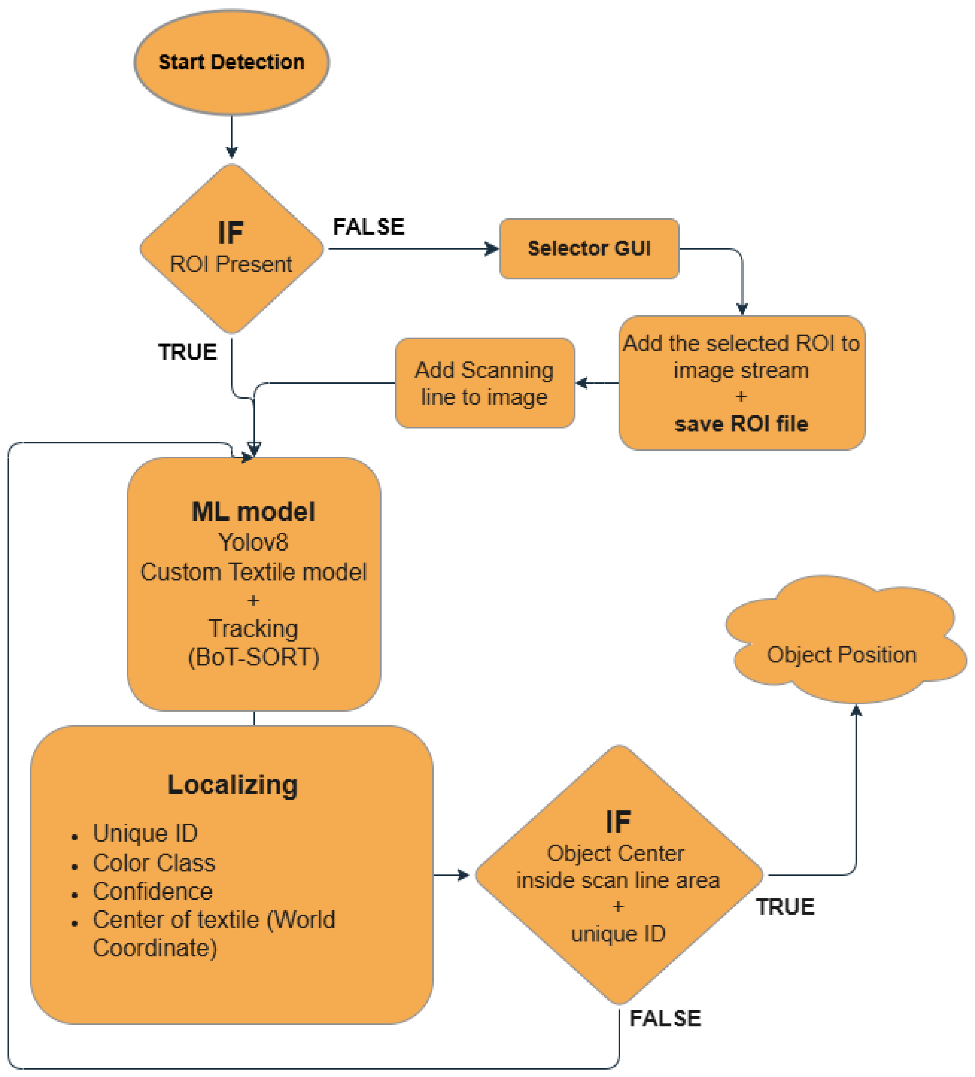
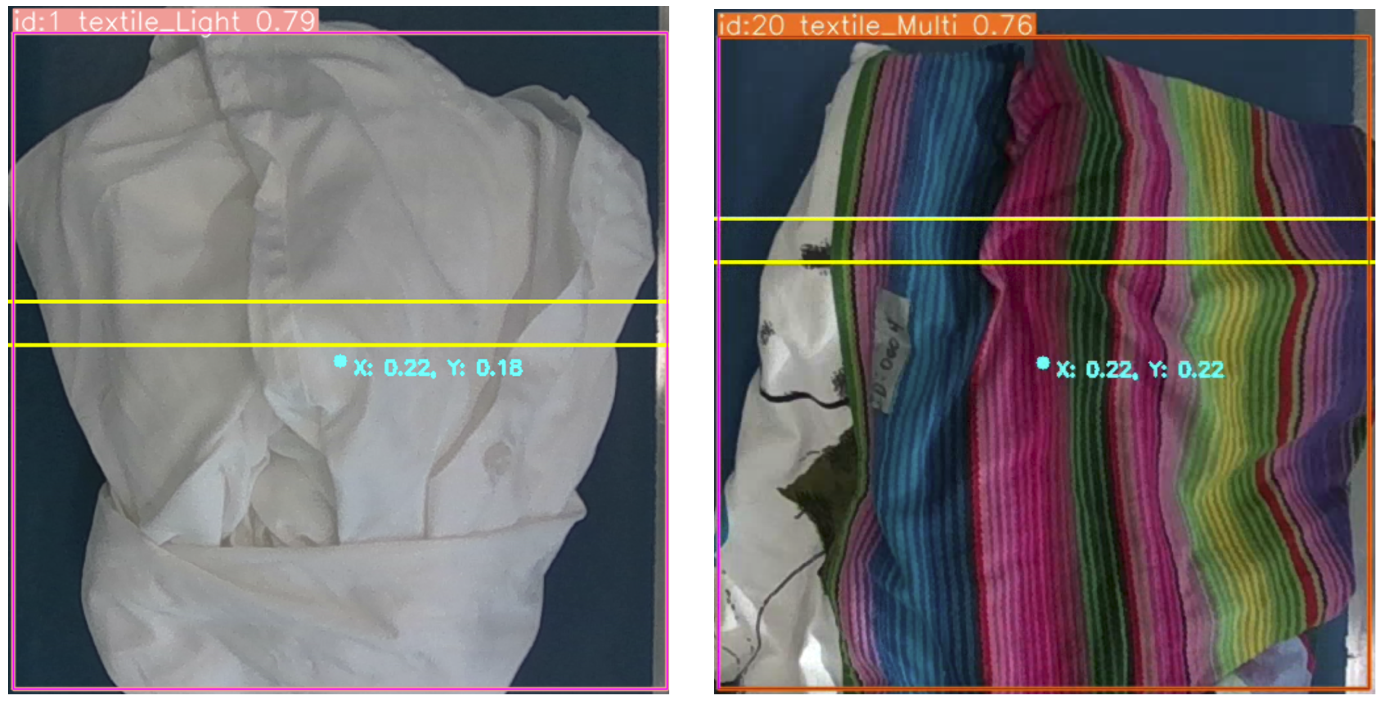
4.2.1. Textile Classification and Localization

The high-level textile color detection is shown in Figure 5. First, the region of interest (ROI) is established. This ensures that the object classification and localization algorithm receives only the necessary image stream for accurate detection. Alternatively, in case the ROI is not established due to random fluctuations while streaming from the camera, changes in the lighting conditions, or any other unseen reasons, to compensate for the potential faults, provision is made for the user to make one using graphical user interface (GUI). Then, the video/images are passed on to the ML module. Here, the custom-trained ML model based on You Only Look Once—YOLOv8—is leveraged to detect the textile class and its center of the bounding box (in pixel coordinate). This information is then passed on to the localization module to convert the pixel coordinate to the world coordinate (only after the required conditions are met). Finally, the textile class and position are obtained and streamed on the Object Position topic.

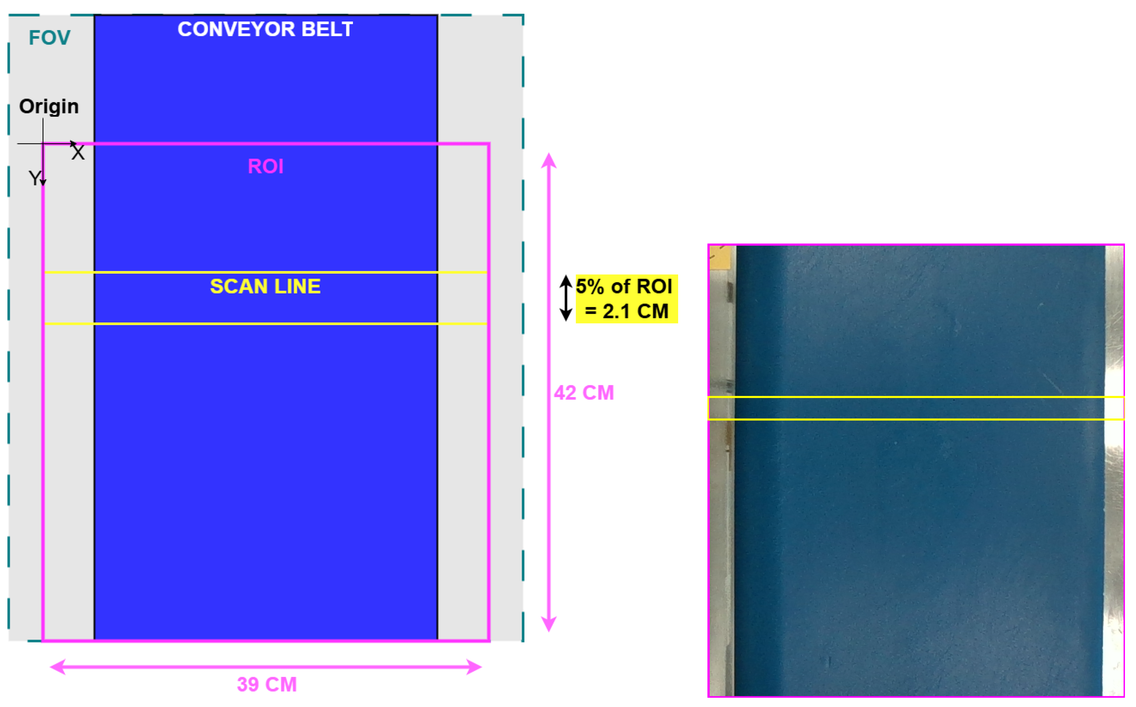
4.2.2. Region of Interest (ROI)

As shown in Figure 6(left), the origin serves as the reference point for converting detected objects from the image frame to the world frame. Essentially, the ROI detection area acts as the primary coordinate system. It is important to note that the robot pickup area has the same geometry but is positioned 1.5 m downstream along the conveyor from the origin of the detection area. Further, a scan line is introduced to ensure that objects detected by the object detection algorithm are processed instantly. It is placed strategically to ensure that all or most of the textiles will be in the frame before the detection data is valid and utilized further. This scan line is the same width as the ROI and 5% of the area of the ROI. In this case, the scan line ( W s l ) is 2.1 cm long and 39 cm wide. The line area is small compared to the ROI to compensate for the inconsistencies in the object detection tracing algorithm. All the dimensions are illustrated in Figure 6(left) with a real image presented in Figure 6(right).
The effectiveness of the scanning line depends on the number of frames involved in the object tracking within the scan line area. To determine this, it is necessary to have knowledge of the conveyor belt speed and the frame rate of the raw RGB camera stream, which is 0.7 m/s and 30 frames per second (FPS), respectively. This information enables the calculation of the duration and that the object center remains in the scan line area, as well as the number of frames available for classification and localization. The time inside the scan line area T s a is given in Equation (1), where W s l and V c b are the length of the scan line and the speed of the conveyor belt, respectively:
T s a = W s l V c b = 0.021 0.07 0.3 s
The frames inside the scan line area F s a are found in Equation (2):
F s a = 30 FPS × T s a = 30 × 0.3 = 9 frames
These parameters can be tuned depending upon the conveyor belt length, speed, and camera frame rate. This also demonstrates the modularity of our proposed system and that the parameters can be tuned and optimized in case of failure.

4.2.3. ML Model

First, a dataset consisting of textiles of various materials and colors is created. For the scope of this manuscript, we have decided to limit the scope to three classes—light, dark, and mixed. The rationale behind this is targeting, e.g., light/white textile used in hospitals, which is one of the major sources of textiles for recycling. Similarly, dark textiles are used in applications ranging from home furnishings to industrial and protective clothing.
The dataset consists of 252 images of textiles with different shapes, colors, and textures on the conveyor belt using the calibrated D455 camera. They are further annotated by leveraging auto-orient; static crop (25–75%) for both the horizontal and vertical regions; and resizing images to a 640 × 640 format with auto-adjust contrast through histogram equalization, rotations of up to ± 9 , and adjusting saturation by up to ± 25 % . With these methods, the dataset comprises 606 images with 531 training images, 50 validation images, and 25 test images. Then, the custom dataset prepared above is used to train YOLOv8m (medium-sized model).
Further, the ML model is trained using the above dataset and YOLOv8m is the base model to detect the textile’s unique ID and class passing through the scan line area. Further, the BoT-SORT tracing algorithm presented by Aharon et al. [35] is used to make sure the same textile holds the same ID and class while moving past the ROI and being scanned. YOLOv8 also gives the coordinates of the top left ( x 1 , y 1 ) and bottom right ( x 2 , y 2 ) corners of the bounding box in the camera coordinate frame.

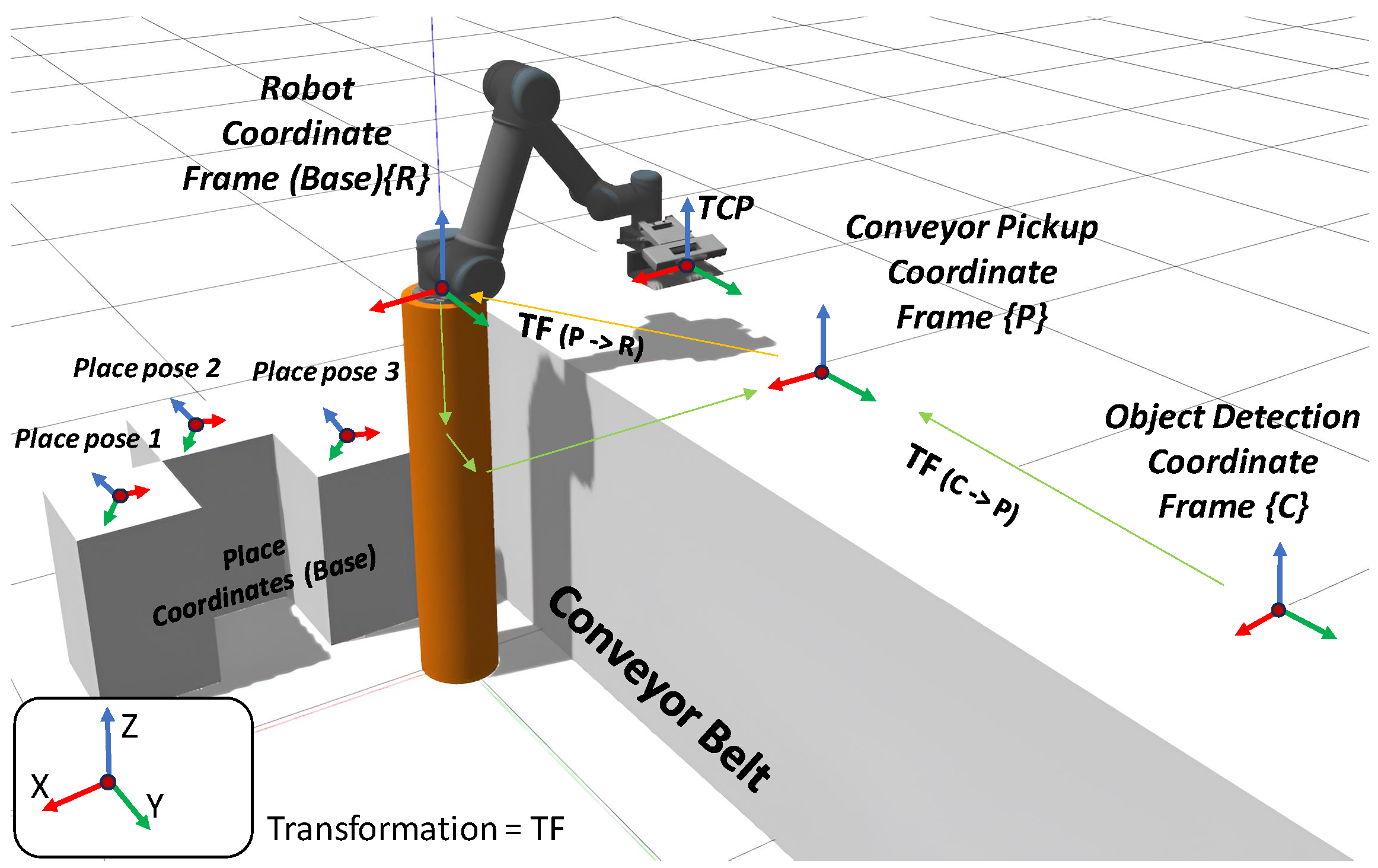
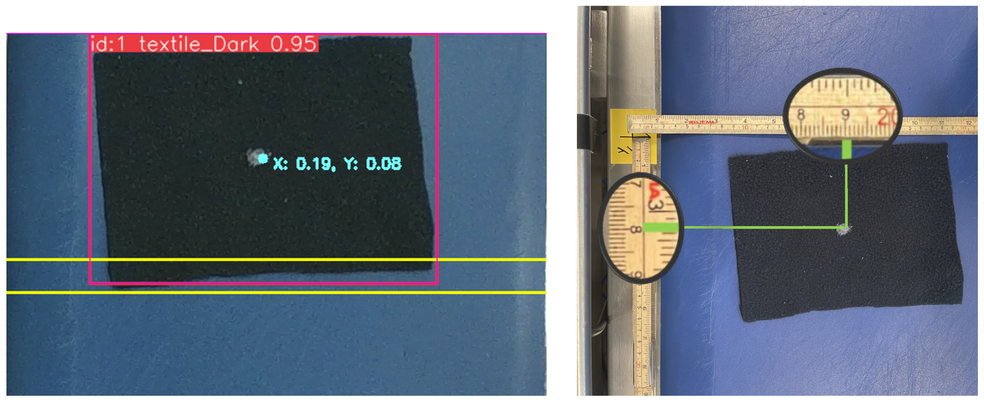
4.2.4. Textile Localization

Subedi et al. [36] further leveraged intrinsic calibration to estimate the intrinsic parameters, namely, f x and f y , which are then used to convert pixel coordinates to camera coordinate frames using Equation (5).
X 1 = x 1 · Z f x Y 1 = y 1 · Z f y
X 2 = x 2 · Z f x Y 2 = y 2 · Z f y
C X = X 1 + X 2 2 100 C Y = Y 1 + Y 2 2 100
where Z is the distance of the textile from the camera (obtained by the built-in lidar system in the D3455 RGB+D camera), and ( X 1 , Y 1 ) , ( X 2 , Y 2 ) , and ( C x , C y ) are the top left, bottom right, and normalized center coordinates of the bounding box of the textile in the world frame.
Finally, as explained in Figure 5, when an object crosses the scanning line, the algorithm verifies whether the center coordinate in the image frame falls within the scanning area and if the ID has not been previously recorded. Then, it verifies that both conditions are met, and a message containing the ID, color class, and the center coordinates of the textile in the world space is sent to the Object Position topic on the ROS2 Network. If not, the detection is ignored; the entire process is repeated again.

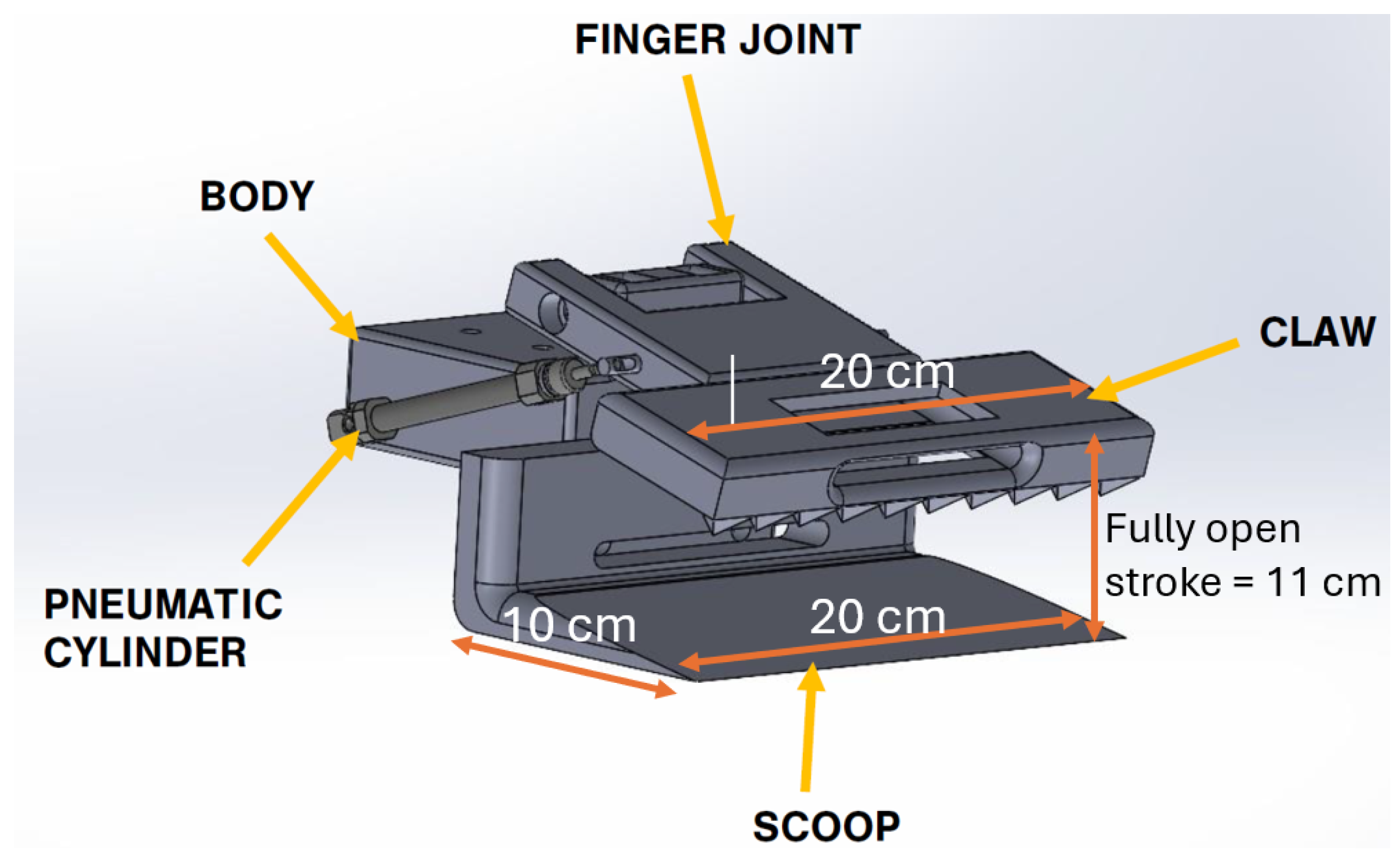
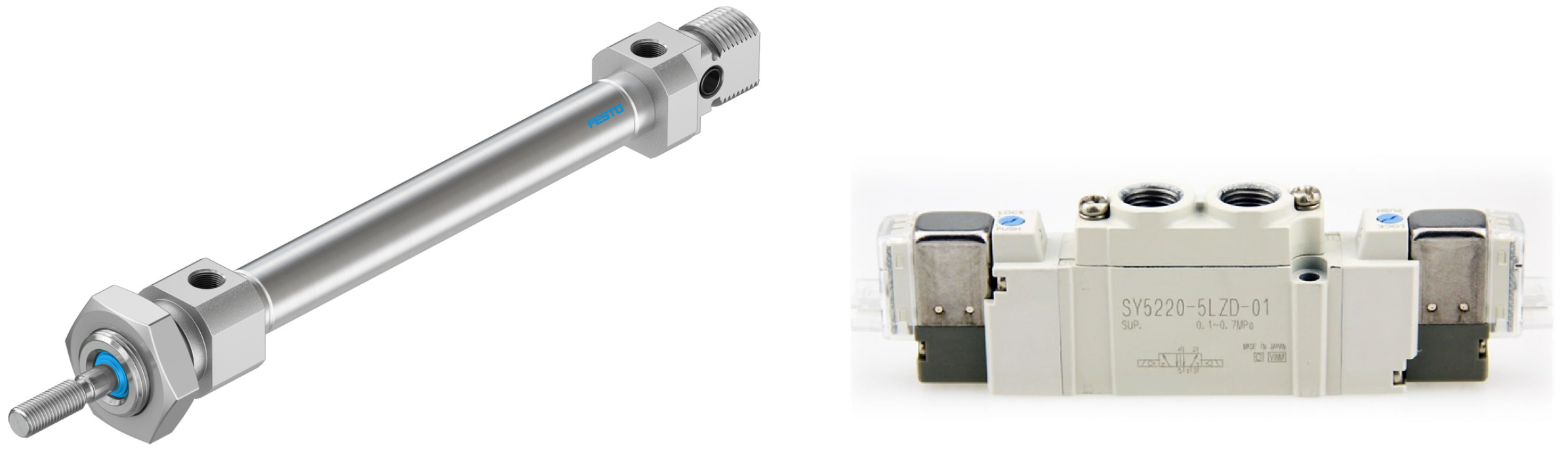
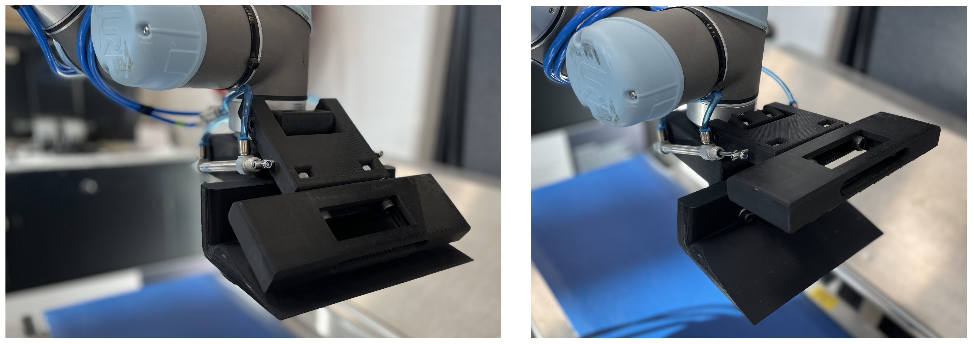
4.2.5. Gripper Design and Development

The gripper is designed to be a minimal viable product (MVP), and to qualify to be an MVP, the gripper must have a low profile to take care of the wrist joint flexible motion and a stroke length of at least 11 cm, a depth of 10 cm (to accommodate the textiles), and a flange hole pattern to match the UR5 tool flange.
The MVP design is based on the principle of making the gripper fingers interchangeable, specifically the scoop and claw, with accessible mounting screws and the ability to align both parts in relation to the body. This design meets the required dimensions illustrated in Figure 7. Given that the conveyor belt is approximately 30 cm wide, the scoop design is set to 20 cm. This allows the robot to adjust to the detected object while maintaining reliability and compensating for irregularities in the pickup position. For this gripper production, all the parts are 3D-printed with polylactide (PLA) material.
Figure 8 and Figure 9 illustrate the pneumatic system designed to actuate the custom robotic gripper developed in this study. Figure 8 presents a schematic pneumatic diagram detailing how two double-acting pneumatic cylinders are interconnected in parallel and controlled via a solenoid valve. This configuration allows for the synchronized extension and retraction of the cylinders, allowing the robotic gripper to effectively open or close to grip and release textiles. Similarly, Figure 9 provides visual details of the actual hardware components used. The left image shows two slim-profile “festo double-acting pneumatic cylinders (DSNU-8 50-P-A)” selected for their compact size and 50 mm stroke length, capable of delivering approximately 30 N of gripping force at 6 bar pressure. The right image highlights the pneumatic solenoid valve, a 5/2 valve electrically actuated at 24 V, responsible for precisely managing the airflow direction to operate the cylinders, thus achieving the controlled gripping motions necessary for delicate and reliable textile manipulation.
The final result of the MVP pneumatic gripper mounted on the UR5 is illustrated in Figure 10. The gripper is now successfully opening and closing the claw as shown in Figure 10(left) and (right), respectively.

4.3. Simulation and Digital Twin

The simulated environment replicates the real workstation within the simulation platform, Gazebo. Its primary objective is to validate the planned trajectories for the UR5 robot, ensuring they are executed correctly without collisions or improper inverse kinematics solutions that could lead to undesirable motion. The “place” boxes and the conveyor belt are represented in the simulated environment as simple geometric shapes with dimensions comparable to their real-world counterparts. The coordinate frames of the system are illustrated in Figure 11. All the targets for the pick-and-place operation are defined in the robot’s base frame (R). However, using transformation relationships between frames, the robot’s picking poses are calculated from the conveyor belt frame (P) and converted into the base frame. This ensures that the target poses for the robot are defined using Cartesian coordinates and quaternions, specifying the position and orientation of the tool center point (TCP). For motion planning between points in the desired sequence, the Open Motion Planning Library (OMPL) [37] is utilized. Specifically, the Rapidly exploring Random Trees (RRT) algorithm, an OMPL-supported motion planner, is employed. This algorithm generates a planned path from point A to point B by randomly sampling points in the state space and iteratively selecting the closest tick to the previous one until the goal is reached [38].
Figure 12(up) provides a high-level overview of the pick procedure, while Figure 12(down) visualizes the corresponding motion sequence. The robot begins in its home position (standby). Upon receiving a pick command along with the textile’s center coordinates in the world frame ( C X , C Y ), the manipulator moves to the “approach” position. At this stage, the gripper is positioned with a 12 cm offset in the Z direction—since the gripper’s full width is 11 cm (see Figure 7)—to prevent any collision with the conveyor belt when fully open. Maintaining this Z offset, the robot moves in the Y direction towards the textile’s center, then transitions to the ‘close gripper’ state before finally moving towards the basket for the placement operation via the “move-out-of-the-way” pose.
Similarly, Figure 13(up) provides a high-level overview of the placement procedure, while Figure 13(down) visualizes the corresponding motion sequence. The placement sequence follows a general structure and is not adjustable, except for the class-specific placement pose. The object can be placed at one of the predefined positions (pose one, two, etc.), depending on the number of classification categories (e.g., color class).

5. System Integration

This section outlines the main flow of the autonomous textile sorting facility, as shown in Figure 2(up). As mentioned in earlier sections, a conveyor belt is used to feed the textiles through the perception system. The green detection zone represents the RGB sensor, which is powered by an object detection algorithm. The RGB sensor detects, classifies, and localizes the textiles for the collaborative robot, which then picks them up in the orange pick zone using a custom-designed gripper to sort them based on these parameters.
All these modules were previously introduced as standalone components, and in this section, they are integrated to function as a complete autonomous textile sorting facility. The facility consists of three separate subsystems that communicate via the ROS2 network. This modular design makes the system highly scalable, allowing for the addition of new sensors to enhance object analysis. It also supports the integration of multiple manipulators to improve handling efficiency for larger volumes. Additionally, a large-scale test is conducted to evaluate the system’s redundancy and performance under various conditions.

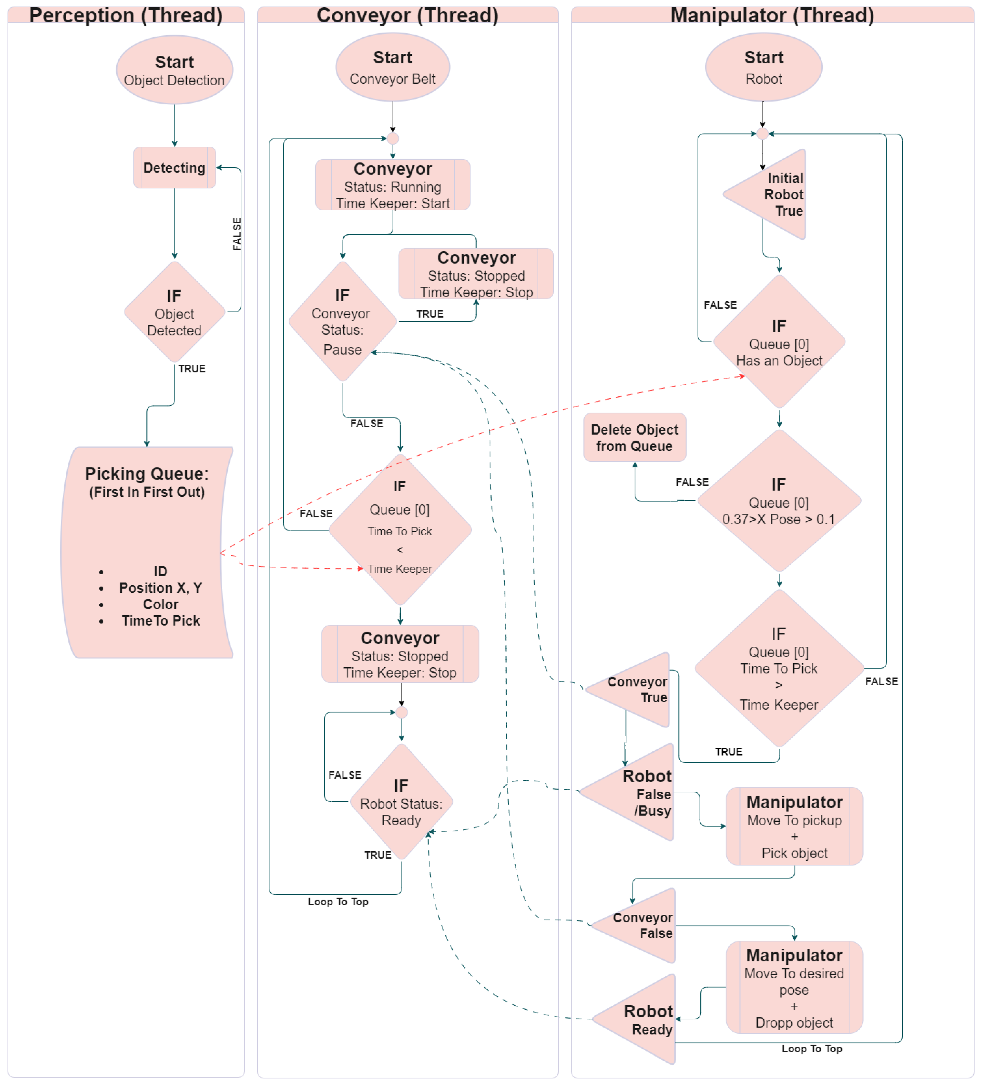
5.1. Multi-Thread Component Integration

A multi-threaded program, shown in Figure 14, is developed to allow multiple components to operate simultaneously and independently. This approach ensures that the different subsystems function seamlessly and efficiently together. The program structure is based on scripts designed to be highly customizable, maintainable, and scalable. All three threads are initiated during the startup sequence and operate independently and continuously. To simplify the understanding of both the flowchart and overall system behavior, each thread’s functionality is clearly presented in the diagram.
During operation, the perception thread continuously monitors the conveyor, detecting, classifying, and localizing textiles as they enter the region of interest. Once detected, each textile receives a unique ID and a calculated “time to be picked” timestamp. This timestamp is computed based on the conveyor belt speed and by transforming coordinates from the camera detection frame (C) to the conveyor pick frame (P). Subsequently, each textile, along with its collected data, is placed into the picking queue. The calculated “time to be picked” timestamp indicates when the textile reaches the pickup point, based on its position, conveyor speed, and coordinate transformations. The system continuously checks this timestamp, focusing on the first textile in the picking queue generated by the perception thread. Once the textile reaches the specified timestamp, the pickup procedure is initiated. When the conveyor timekeeper matches the first detected textile’s pick time, the conveyor belt and timekeeper stop. The conveyor thread will then loop and check if the conveyor-pause status flag is false and the robot-ready status flag is true to continue. These flags are toggled by the manipulator thread. The manipulator thread also checks if the position of the first textile in the queue is within the width of the pick zone and whether the object has reached the pickup zone. After the textile reaches the pickup zone, and the timing requirements are met by both threads, the conveyor-pause flag is set to true, and the robot-ready flag is set to busy. This double flag ensures redundancy in the facility’s timing. Once the fabric is picked and the manipulator is clear of the picking zone, the conveyor-pause flag is set to false. The conveyor thread then resumes operation. After completing the placing sequence, the robot-ready flag is reset to ready. This process repeats for each detected textile on the conveyor belt. With these status flags and logic, the multithreading program ensures correct timing within the autonomous textile sorting facility.

5.2. Perception Thread

Object detection is a part of the perception system, and it constantly detects and publishes the object’s color and position information. Upon detection, the perception thread checks whether the object specifications have been previously identified; if the object is unique, it is added to the picking queue following a first-in, first-out (FIFO) method. Each queue entry contains details, such as the object’s ID, position, color, and scheduled pickup time. At this stage, a short-term memory function ensures the same object is not repeatedly processed.

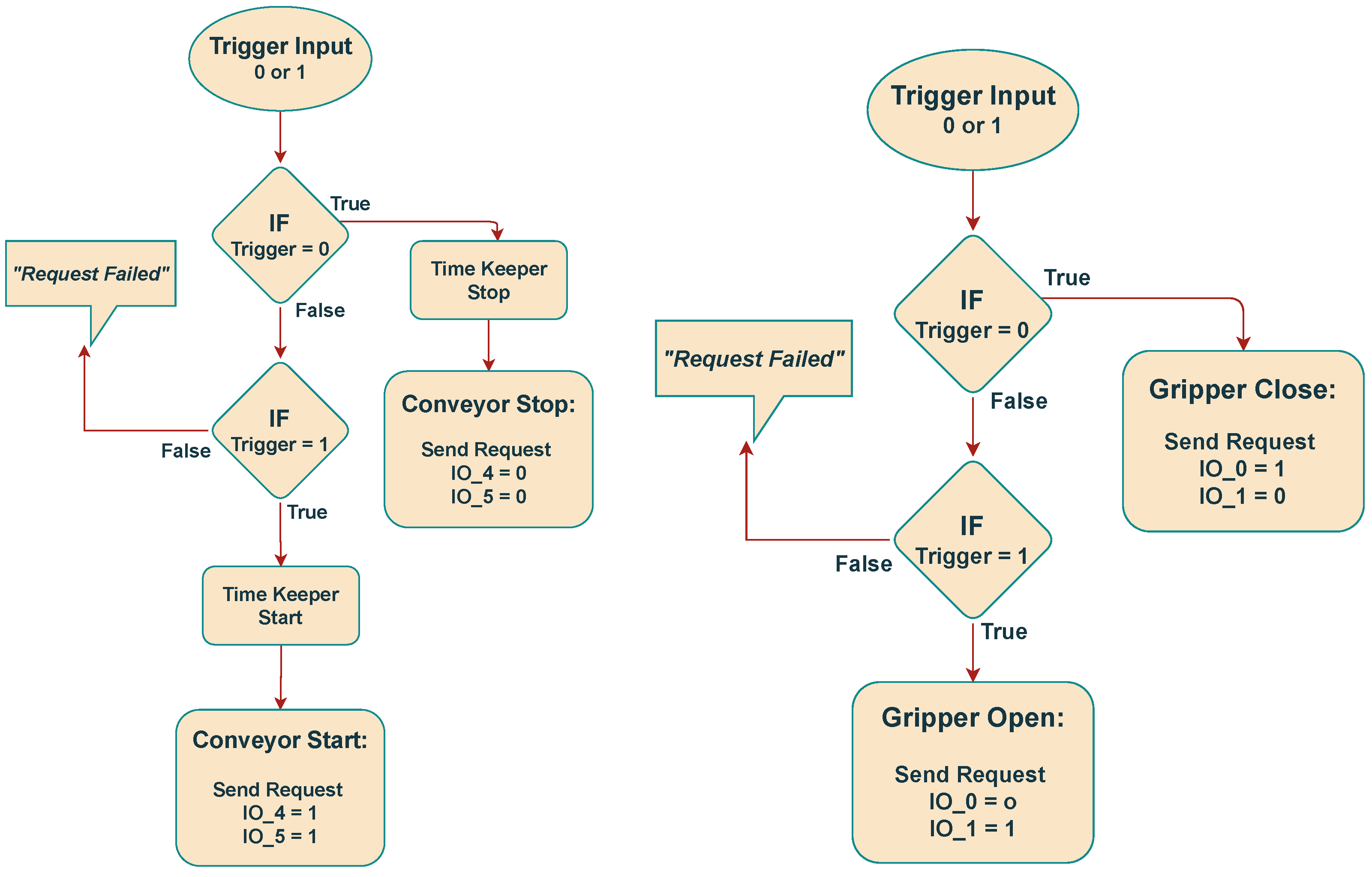
5.3. Conveyor Thread

The conveyor belt is connected to the digital outputs (IO) of the UR5 robot controller. These digital outputs function as an ON/OFF toggle to start and stop the conveyor belt, while its speed is adjusted manually using a knob on the control unit. The logic behind this operation is outlined in the flowchart illustrated in Figure 15(left). The conveyor belt acts as the master module of the sorting facility, controlling the synchronization of object transport. Specifically, the conveyor manages the timing of operations by halting or resuming movement based on commands received from the manipulator thread. When the conveyor belt is paused, the associated digital output is set to OFF, and when it resumes, the output is switched to ON. This ensures accurate timing for the picking position, while the conveyor speed control remains manually adjustable via the knob on the control unit.

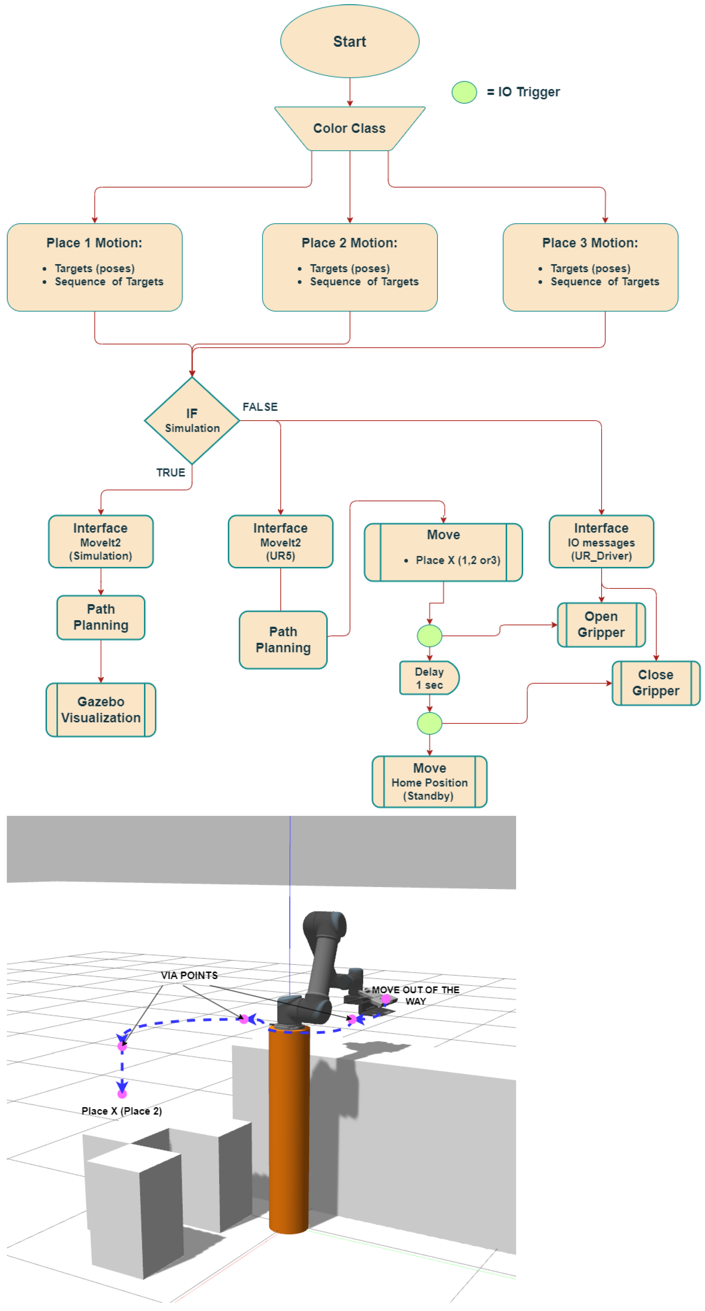
5.4. Manipulator Thread

The conveyor belt gripper is connected to the UR5 robot controller via digital outputs (IO), allowing the gripper to open or close by toggling these outputs through the robot controller. The toggling of the digital outputs during the pick-and-place sequences is illustrated in the flowchart shown in Figure 15(right). The pick cycle takes approximately 10 s, while the place cycle requires approximately 30 s. Activation of the gripper is controlled digitally by sending IO signals from the manipulator thread via ROS2 communication.

6. Results

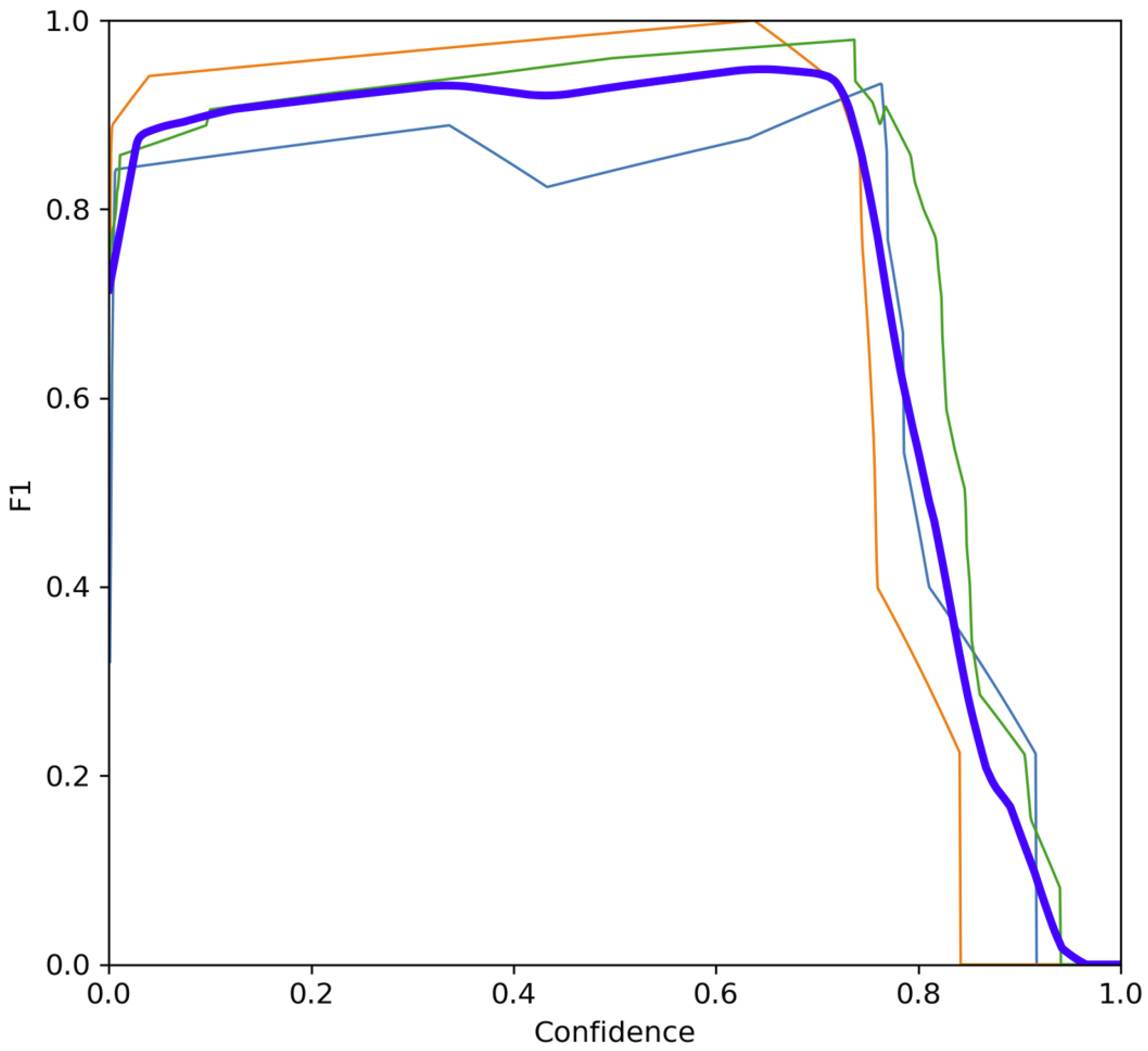
6.1. Textile Detection and Localization

The normalized confusion matrix on the test dataset is obtained after implementing textile detection and localization and is shown in Figure 16. It is observed that the model can detect different classes of textiles, namely, dark, white, and mixed color textiles, with 100% accuracy. Further, the model’s performance, evaluated based on the F1 score, is shown in Figure 17. The F1 score Curve represents a performance score in diverse confidence values based on the balance between false positives and false negatives. The model achieved an F1 score of 0.95 with a confidence factor of 0.65. This also complements the basis for high accuracy (obtained from the confusion matrix in Figure 16).
The performance of object detection and the correct calibration are important when it comes to picking the objects correctly. Further, leveraging Equations (3)–(5), the pixel coordinate obtained from the ML model is transformed to the camera coordinate. Further, the camera is located at the known calibrated position relative to the world. Hence, the pixel coordinate is transferred to the world frame. This is shown in Figure 18(left) and validated with the real-world measurement in Figure 18(right). It is observed that while the former localizes the center of the textile to be x : 0.19 , y : 0.08 m, respectively, the latter also gives similar results. Further, for illustration purposes, some instance of examples from the different classes are also shown in Figure 19.

6.2. Gripper Design and Development

The gripper is explicitly designed for the task. In addition, experience with Universal Robots and integrating custom grippers played a crucial role in the implementation process. The gripper, illustrated in Figure 10, is evaluated for grip strength using a standard kitchen scale. The tests demonstrated a maximum gripping force of approximately 10 N (around 1 kg equivalent, shown in Figure 20). The claw design helps it anchor securely into fabrics, enabling the gripper to reliably hold the textiles even when scooped or held at an angle, as shown in Figure 21(left) and (right), respectively.

6.3. System Integration

The integrated system described in Section 5 was implemented and tested end-to-end for a total of 60 trials. Out of these 60 attempts, 51 were successful, while 9 were unsuccessful in detecting, classifying, localizing, picking, or placing the objects. Specifically, out of 60 trials, 20 attempts were conducted on light textiles. Among these attempts, unsuccessful cases were distributed across the textile detection, localization, picking, classification, and placement tasks. Multi-step failures occurred in some unsuccessful attempts. More specifically, (a) the textile was undetected and consequently not picked up, which might be because of the low contrast between the conveyor belt color and the textile color; (b) misclassifications led to correct picking but incorrect placement in the wrong bin; and (c) the textile was detected and classified, but the localization was incorrect, which resulted in wrong timing calculations. The detailed results are illustrated in Figure 22.

7. Conclusions and Future Work

In this paper, we proposed an autonomous textile sorting system demonstrating a scalable and efficient solution for addressing the challenges of textile recycling. Integrating advanced computer vision and machine learning with robotic automation, the system enables the real-time classification, localization, and sorting of textiles on a moving conveyor belt. The custom-designed pneumatic gripper enhances versatility in handling various textile types, while the multi-threaded software architecture ensures seamless coordination between the system components. Additionally, digital simulation aids in optimizing robotic motion before real-world deployment, improving system reliability and safety. By keeping the abstraction at perception, ML algorithms, and robotic manipulation, this proposed method is modular and scalable. The implementation of queuing management, multithreading optimization, and advanced material detection further strengthens the system’s capability for industrial-scale recycling automation. Backed by multiple experiments, we demonstrated that our proposed framework can perform end-to-end textile sorting dynamically. This work contributes to the development of sustainable and automated textile recycling solutions, supporting circular economy initiatives and reducing the environmental impact of textile waste.
Future advancements will focus on expanding the dataset and integrating a camera and an NIR spectrometer for both material and color classifications. Further, in this work, we consider that the environment is static and there is no dynamic positioning of the objects in the scene. A future work direction could also be towards human–robot interaction, including safety in dynamic environments. Among the other works, methods based on impedance learning for human-guided robots in unknown and dynamic environments could be explored [39]. Further, leveraging an iterative learning controller for compensation for position-dependent disturbances for safer robotic motion can be implemented.

Author Contributions

Conceptualization, A.J., I.T. and T.S.H.; methodology, A.J., I.T. and T.S.H.; software, T.S.H.; validation, A.J. and T.S.H.; formal analysis, A.J. and I.T.; investigation, A.J. and I.T.; resources, I.T.; data curation, T.S.H.; writing—original draft preparation, T.S.H.; writing—review and editing, A.J. and I.T.; visualization, T.S.H.; supervision, A.J. and I.T.; project administration, I.T.; funding acquisition, I.T. All authors have read and agreed to the published version of the manuscript.

Funding

This work is partly supported by Regionale Forskningsfond Agder through the ISORTx project number 341372.

Data Availability Statement

Will be considered on request.

Acknowledgments

The authors would also like to thank UFF, Norway, for providing the textile samples.

Conflicts of Interest

The authors declare no conflicts of interest.

References

  1. Sondh, S.; Upadhyay, D.S.; Patel, S.; Patel, R.N. Strategic approach towards sustainability by promoting circular economy-based municipal solid waste management system- A review. Sustain. Chem. Pharm. 2024, 37, 101337. [Google Scholar] [CrossRef]
  2. Ma, W.; Liu, T.; Hao, J.L.; Wu, W.; Gu, X. Towards a circular economy for construction and demolition waste management in China: Critical success factors. Sustain. Chem. Pharm. 2023, 35, 101226. [Google Scholar] [CrossRef]
  3. Molla, A.H.; Shams, H.; Harun, Z.; Kasim, A.N.C.; Nallapaneni, M.K.; Rahman, M.N.A. Evaluation of end-of-life vehicle recycling system in India in responding to the sustainability paradigm: An explorative study. Sci. Rep. 2023, 13, 4169. [Google Scholar] [CrossRef]
  4. Angelo, A.C.M.; Saraiva, A.B.; Clímaco, J.C.N.; Infante, C.E.; Valle, R. Life Cycle Assessment and Multi-criteria Decision Analysis: Selection of a strategy for domestic food waste management in Rio de Janeiro. J. Clean. Prod. 2017, 143, 744–756. [Google Scholar] [CrossRef]
  5. Mishra, K.; Siwal, S.S.; Thakur, V.K. E-waste recycling and utilization: A review of current technologies and future perspectives. Curr. Opin. Green Sustain. Chem. 2024, 47, 100900. [Google Scholar] [CrossRef]
  6. Voukkali, I.; Papamichael, I.; Loizia, P.; Economou, F.; Stylianou, M.; Naddeo, V.; Zorpas, A.A. Fashioning the Future: Green chemistry and engineering innovations in biofashion. Chem. Eng. J. 2024, 497, 155039. [Google Scholar] [CrossRef]
  7. Papamichael, I.; Chatziparaskeva, G.; Pedreño, J.N.; Voukkali, I.; Almendro Candel, M.B.; Zorpas, A.A. Building a new mind set in tomorrow fashion development through circular strategy models in the framework of waste management. Curr. Opin. Green Sustain. Chem. 2022, 36, 100638. [Google Scholar] [CrossRef]
  8. De Ponte, C.; Liscio, M.C.; Sospiro, P. State of the art on the Nexus between sustainability, fashion industry and sustainable business model. Sustain. Chem. Pharm. 2023, 32, 100968. [Google Scholar] [CrossRef]
  9. Papamichael, I.; Voukkali, I.; Economou, F.; Loizia, P.; Demetriou, G.; Esposito, M.; Naddeo, V.; Liscio, M.C.; Sospiro, P.; Zorpas, A.A. Mobilisation of textile waste to recover high added value products and energy for the transition to circular economy. Environ. Res. 2024, 242, 117716. [Google Scholar] [CrossRef]
  10. Chioatto, E.S.P. Transition from waste management to circular economy: The European Union roadmap. Environ. Dev. Sustain. 2023, 25, 249–276. [Google Scholar] [CrossRef]
  11. Bianchi, S.; Bartoli, F.; Bruni, C.; Fernandez-Avila, C.; Rodriguez-Turienzo, L.; Mellado-Carretero, J.; Spinelli, D.; Coltelli, M.B. Opportunities and Limitations in Recycling Fossil Polymers from Textiles. Macromol 2023, 3, 120–148. [Google Scholar] [CrossRef]
  12. Riba, J.R.; Cantero, R.; Canals, T.; Puig, R. Circular economy of post-consumer textile waste: Classification through infrared spectroscopy. J. Clean. Prod. 2020, 272, 123011. [Google Scholar] [CrossRef]
  13. Bonifazi, G.; D’Adamo, I.; Palmieri, R.; Serranti, S. Recycling-Oriented Characterization of Space Waste Through Clean Hyperspectral Imaging Technology in a Circular Economy Context. Clean Technol. 2025, 7, 26. [Google Scholar] [CrossRef]
  14. Tsai, P.F.; Yuan, S.M. Using Infrared Raman Spectroscopy with Machine Learning and Deep Learning as an Automatic Textile-Sorting Technology for Waste Textiles. Sensors 2025, 25, 57. [Google Scholar] [CrossRef]
  15. Miao, Z.; Yao, L.; Zeng, F.; Wang, Y.; Hong, Z. Feature Fusion-Based Re-Ranking for Home Textile Image Retrieval. Mathematics 2024, 12, 2172. [Google Scholar] [CrossRef]
  16. Owczarek, M. A New Method for Evaluating the Homogeneity within and between Weave Repeats in Plain Fabric Structures Using Computer Image Analysis. Materials 2024, 17, 3229. [Google Scholar] [CrossRef]
  17. Behera, M.; Nayak, J.; Banerjee, S.; Chakrabortty, S.; Tripathy, S.K. A review on the treatment of textile industry waste effluents towards the development of efficient mitigation strategy: An integrated system design approach. J. Environ. Chem. Eng. 2021, 9, 105277. [Google Scholar] [CrossRef]
  18. Wojnowska-Baryła, I.; Bernat, K.; Zaborowska, M.; Kulikowska, D. The Growing Problem of Textile Waste Generation—The Current State of Textile Waste Management. Energies 2024, 17, 1528. [Google Scholar] [CrossRef]
  19. Araye, A.A.; Yusoff, M.S.; Awang, N.A.; Abd Manan, T.S.B. Evaluation of the Methane (CH4) Generation Rate Constant (k Value) of Municipal Solid Waste (MSW) in Mogadishu City, Somalia. Sustainability 2023, 15, 4531. [Google Scholar] [CrossRef]
  20. Khan, D.; Baek, M.; Kim, M.Y.; Seog Han, D. Multimodal Object Detection and Ranging Based on Camera and Lidar Sensor Fusion for Autonomous Driving. In Proceedings of the 2022 27th Asia Pacific Conference on Communications (APCC), Jeju Island, Republic of Korea, 19–21 October 2022; pp. 342–343. [Google Scholar] [CrossRef]
  21. Sahba, R.; Sahba, A.; Sahba, F. Using a Combination of LiDAR, RADAR, and Image Data for 3D Object Detection in Autonomous Vehicles. In Proceedings of the 2020 11th IEEE Annual Information Technology, Electronics and Mobile Communication Conference (IEMCON), Online, 4–7 November 2020; pp. 0427–0431. [Google Scholar] [CrossRef]
  22. Chen, Z.; Yang, J.; Li, F.; Feng, Z.; Chen, L.; Jia, L.; Li, P. Foreign Object Detection Method for Railway Catenary Based on a Scarce Image Generation Model and Lightweight Perception Architecture. IEEE Trans. Circuits Syst. Video Technol. 2025, 1. [Google Scholar] [CrossRef]
  23. Yan, L.; Wang, Q.; Zhao, J.; Guan, Q.; Tang, Z.; Zhang, J.; Liu, D. Radiance Field Learners As UAV First-Person Viewers. In Proceedings of the Computer Vision—ECCV 2024; Leonardis, A., Ricci, E., Roth, S., Russakovsky, O., Sattler, T., Varol, G., Eds.; Springer Nature: Cham, Switzerland, 2025; pp. 88–107. [Google Scholar]
  24. Zhang, B.; Xie, Y.; Zhou, J.; Wang, K.; Zhang, Z. State-of-the-art robotic grippers, grasping and control strategies, as well as their applications in agricultural robots: A review. Comput. Electron. Agric. 2020, 177, 105694. [Google Scholar] [CrossRef]
  25. Samadikhoshkho, Z.; Zareinia, K.; Janabi-Sharifi, F. A Brief Review on Robotic Grippers Classifications. In Proceedings of the 2019 IEEE Canadian Conference of Electrical and Computer Engineering (CCECE), Edmonton, AB, Canada, 5–8 May 2019; pp. 1–4. [Google Scholar] [CrossRef]
  26. Fenjan, S.Q.; Dehkordi, S.F. Design and Fabrication of a Pneumatic Soft Robot Gripper Using Hyper-Flexible Silicone. In Proceedings of the 2023 11th RSI International Conference on Robotics and Mechatronics (ICRoM), Tehran, Iran, 19–21 December 2023; pp. 641–646. [Google Scholar] [CrossRef]
  27. Ji, D.; Lee, J.; Jin, M. Design and control of hybrid Flexible robotic gripper with high stiffness and stability. In Proceedings of the 2022 13th Asian Control Conference (ASCC), Jeju, Republic of Korea, 4–7 May 2022; pp. 2503–2505. [Google Scholar] [CrossRef]
  28. Ariyanto, M.; Munadi, M.; Setiawan, J.; Mulyanto, D.; Nugroho, T. Three-Fingered Soft Robotic Gripper Based on Pneumatic Network Actuator. In Proceedings of the 2019 6th International Conference on Information Technology, Computer and Electrical Engineering (ICITACEE), Semarang, Indonesia, 26–27 September 2019; pp. 1–5. [Google Scholar] [CrossRef]
  29. Heikkilä, P.; Harlin, A.; Heikkinen, H.; Tuovinen, J.; Kuittinen, S. Textile Recognition and Sorting for Recycling at an Automated Line Using NIR Spectroscopy. Recycling 2023, 6, 11. [Google Scholar] [CrossRef]
  30. Spyridis, Y.; Argyriou, V.; Sarigiannidis, A.; Radoglou, P.; Sarigiannidis, P. Autonomous AI-enabled Industrial Sorting Pipeline for Advanced Textile Recycling. In Proceedings of the 2024 20th International Conference on Distributed Computing in Smart Systems and the Internet of Things (DCOSS-IoT), Abu Dhabi, United Arab Emirates, 29 April–1 May 2024. [Google Scholar] [CrossRef]
  31. Luo, J.; Zhang, Z.; Wang, Y.; Feng, R. Robot Closed-Loop Grasping Based on Deep Visual Servoing Feature Network. Actuators 2025, 14, 25. [Google Scholar] [CrossRef]
  32. Morrison, D.; Corke, P.; Leitner, J. Multi-view picking: Next-best-view reaching for improved grasping in clutter. In Proceedings of the 2019 International Conference on Robotics and Automation (ICRA), Montreal, QC, Canada, 20–24 May 2019. [Google Scholar] [CrossRef]
  33. ASEE PEER. Modular Conveyor Belt System with Robotic Sorting. 2019. Available online: https://peer.asee.org/modular-conveyor-belt-system-with-robotic-sorting (accessed on 1 March 2024).
  34. ROS 2 Humble Documentation. 2023. Available online: https://docs.ros.org/en/humble/index.html (accessed on 1 March 2024).
  35. Aharon, N.; Orfaig, R.; Bobrovsky, B.Z. BoT-SORT: Robust Associations Multi-Pedestrian Tracking. arXiv 2022, arXiv:2206.14651. [Google Scholar]
  36. Subedi, D.; Jha, A.; Tyapin, I.; Hovland, G. Camera-LiDAR Data Fusion for Autonomous Mooring Operation. In Proceedings of the 2020 15th IEEE Conference on Industrial Electronics and Applications (ICIEA), Kristiansand, Norway, 9–13 November 2020; pp. 1176–1181. [Google Scholar] [CrossRef]
  37. The Open Motion Planning Library. Available online: https://ompl.kavrakilab.org/ (accessed on 20 May 2024).
  38. OMPL Geometric RRT Class Reference. Available online: https://ompl.kavrakilab.org/classompl_1_1geometric_1_1RRT.html (accessed on 20 May 2024).
  39. Xing, X.; Burdet, E.; Si, W.; Yang, C.; Li, Y. Impedance Learning for Human-Guided Robots in Contact With Unknown Environments. IEEE Trans. Robot. 2023, 39, 3705–3721. [Google Scholar] [CrossRef]
Figure 1. Contributions made in this work. This work presents end-to-end autonomous textile classification towards a circular economy. It includes three functions: (a) textile detection and classification, (b) a custom 3D-printed pneumatic gripper is designed to pick the textiles from a moving conveyor belt, and (c) further, the gripper is mounted on a robot for autonomous pick-and-place operation. Finally, the end-to-end experiment is performed by integrating all the parts, both hardware and software, through the connected multithreading network for textile detection, classification, localization, and pick and place from the moving conveyor belt at various speeds simulating real-world use cases.
Electronics 14 02706 g001
Figure 2. An overview of the physical system: (up) A system overview of the experimental setup with the descriptive zones. Loading zone: used to load the textile to be sorted, RGB CAM/detection zone: the region where the detection of the material color takes place, NIR CAM/detect zone (future work, see Section 7), pickup zone: the region where the robotic pick operation takes place, and collaborative robot: the agent that performs the autonomous pick and place operations for the textile sorting. (down) The placing position for each textile class. e.g., Bin A, B and C is used to place light, dark and multi colored textile.
Electronics 14 02706 g002
Figure 3. High-level system overview. Camera streams RGB+D images of the textile placed on the conveyor belt to the computing and coordinating platform. This performs the related functionalities and updates the UR5 robot for pick, place, and sort operations. Further, the UR5 controller operates the gripper and the conveyor belt is also controlled through electrical input/output (I/O) pins.
Electronics 14 02706 g003
Figure 4. Software architecture and implementation of different functionalities for textile sorting. Frames from the Intel RealSense D455 camera (Node: Realsense D455 Camera) are published to specific topics. The Object Publisher Node and My Subscriber Node process these frames to identify the textile’s color, position on the conveyor, and ID. This data is sent to the Motion Planning Node, which generates the trajectory and forwards it to the hardware controller for robot execution.
Electronics 14 02706 g004
Figure 5. Flowchart explaining object detection using ML model.
Electronics 14 02706 g005
Figure 6. Region of interest with scan line: (left) dimensions of region of interest; (right) image from video stream region of interest.
Electronics 14 02706 g006
Figure 7. CAD model of the finished assembled pneumatic gripper parts explanation.
Electronics 14 02706 g007
Figure 8. Pneumatic diagram for the custom gripper.
Electronics 14 02706 g008
Figure 9. Pneumatic hardware for custom gripper: (left) festo double-acting pneumatic cylinder DSNU-8 50-P-A with 50 mm stroke; (right) pneumatic solenoid 5/2 valve 24 V.
Electronics 14 02706 g009
Figure 10. Custom-made pneumatic gripper actions: (left) front view closed gripper; (right) front view open gripper.
Electronics 14 02706 g010
Figure 11. Gazebo simulation environment representing the textile sorting workstation, including coordinate frames.
Electronics 14 02706 g011
Figure 12. (up) High-level flowchart of the pick-object script. To implement a pickup motion, all the targets are generated. If a simulation in Gazebo is needed, path planning is implemented in MoveIt2 and visualized in Gazebo and RViz. If the path is executed on a UR5 robot, MoveIt2 generates a trajectory. ROS2 governs all the operations, such as moving the robot to a pickup position, opening and closing the gripper, picking the object, and moving to an “out-of-the-way” pose. (down) Sequence of pick poses.
Electronics 14 02706 g012
Figure 13. Place motion script: (up) High-level flowchart of the object placement script. Based on the detected color class in the detection phase, an appropriate placement target is defined. In the simulation mode, the trajectory is generated by MoveIt and visualized in Gazebo and RViz. If a UR5 robot is used, the ROS-to-robot-controller interface is initiated; MoveIt then generates the trajectory based on the detected color class, the robot moves to the correct pose, and the gripper opens and closes to drop the object. Finally, the robot returns to its home position. (down) Sequence of the placement poses.
Electronics 14 02706 g013
Figure 14. A high-level flowchart representation of the multi-threaded system for coordinating perception, conveyor belt, and robotic manipulation functionalities.
Electronics 14 02706 g014
Figure 15. (left) Conveyor belt IO toggle flowchart. (right) Gripper IO toggle flowchart.
Electronics 14 02706 g015
Figure 16. Normalized confusion matrix on test dataset. All the diagonal elements in the confusion matrix are 100%, demonstrating that the model attains high accuracy with no false positive and false negative.
Electronics 14 02706 g016
Figure 17. F1 score of individual classes: dark textile (light blue), light textile (orange), and multicolored textile (green) together with overall F1 score across all classes (dark blue). For all the cases, the F1 score is above 80% at 65% confidence. This shows that model has lower false positives and false negatives. This also confirms that the mode is trained well and is able to classify the textile material with high accuracy.
Electronics 14 02706 g017
Figure 18. Textile detection, classification, and localization (in this case the dark textile) using the ML model and pixel-to-world coordinate transformation (left) compared against the real-world measurement (right). It is observed that the proposed method estimates the center of the textile to be x = 19 cm and y = 8 cm in the world coordinate frame (compared to the ground truth of 19 and 8 cm, respectively).
Electronics 14 02706 g018
Figure 19. Validation of ML-based textile detection, classification, and localization on other classes, namely, light textile (left) and multicolored textile (right). In this example, the center of the white textile is at x = 22 and y = 18 cm, and for the multicolored textile, it lies at x = 22 and y = 22 cm in the world coordinate frame.
Electronics 14 02706 g019
Figure 20. Gripper strength test: 1.07 kg force (10.5 N). It is observed that the gripper has the force required to pick and place the textile.
Electronics 14 02706 g020
Figure 21. Gripper scoop and holding tests: (left) gripper test on belt with scoop successfully under the textile; (right) gripper test tilted with gripping bunched-up textile.
Electronics 14 02706 g021
Figure 22. Column chart describing the total successful and unsuccessful end-to-end tasks of textile detection, localization, and sorting operations, including pick and place.
Electronics 14 02706 g022
Disclaimer/Publisher’s Note: The statements, opinions and data contained in all publications are solely those of the individual author(s) and contributor(s) and not of MDPI and/or the editor(s). MDPI and/or the editor(s) disclaim responsibility for any injury to people or property resulting from any ideas, methods, instructions or products referred to in the content.

