Article

Toward High Bit Rate LoRa Transmission via Joint Frequency-Amplitude Modulation

1
School of Information Science and Engineering, Yanshan University, Qinhuangdao 066004, China
2
Hebei Key Laboratory of Information Transmission and Signal Processing, Qinhuangdao 066004, China
*
Author to whom correspondence should be addressed.
Electronics 2025, 14(13), 2687; https://doi.org/10.3390/electronics14132687
Submission received: 14 May 2025 / Revised: 28 June 2025 / Accepted: 29 June 2025 / Published: 2 July 2025

Abstract

Long Range (LoRa) is one of the promising Low-Power Wide-Area Network technologies to achieve a strong anti-noise ability due to the modulation of the chirp spread spectrum in low-power and long-distance communications. However, LoRa suffers the problem of packet collisions. Hence, we propose QR−LoRa, a novel PHY-layer scheme that can transmit data in both amplitude and frequency dimensions simultaneously. For the amplitude modulation, we modulate the constant envelope of a LoRa chirp with a cyclic right-shifted ramp signal, where the cyclic right-shifted position carries the data of the amplitude modulation. We adopt the standard LoRa for frequency modulation. We prototype QR−LoRa on the software-defined radio platform USRP N210 and evaluate its performance via simulations and field experiments. The results show the bit rate gain of QR−LoRa is up to 2× compared with the standard LoRa device.

1. Introduction

The Low-Power Wide-Area Network (LPWAN) has become one of the most promising solutions for achieving ubiquitous connectivity due to its long-distance and low-power characteristics. It has attracted extensive attention from industry and academia [1]. Long Range (LoRa) [2], SIGFOX [3], and NB-IoT [2] are the three commercialized wireless technologies facilitating the LPWAN development. LoRa is the most promising technology among them for IoT connectivity outdoors [4]. It is an open-source technique operating at the unlicensed ISM Sub-GHz bands without subscription fees [5,6,7].
Recently, the ubiquitous connection puts forward higher requirements for the maximum rate, reliability and low power consumption of the IoT device. However, the low bit rate of LoRa (37.5 Kbps) limits its potential applications  [8]. In addition, serious packet collisions occur at the receiving gateway when multiple LoRa nodes transmit packets on the same frequency channel at the same time [9,10,11]. Even worse, the low bit rate of LoRa leads to a long packet duration, which further aggravates this problem, decreasing the network throughput and increasing the energy consumption  [12].
In order to improve the data rate of the LoRa transmission, many representative efforts have been proposed. They are roughly categorized into two types: Single Chirp (SC) and Multiple Chirp (MC). For the SC schemes, ICS-LoRa [13] increases by 1-bit extra data on top of each symbol by introducing a new kind of basic chirp, which improves the information transmission rate S F + 1 2 S F B W , where S F is the spreading factor and B W indicates the operating bandwidth. SSK-LoRa [14] proposes a symbol scheme using the improved ICS-LoRa chirp, which overcomes the signal-to-noise ratio (SNR) loss brought by ICS-LoRa, yet keeps the same data rate as ICS-LoRa. PSK-LoRa [15] proposes to divide the information into two parts, in which one part determines the initial frequency of LoRa symbols and the other part uses PSK modulation to determine the initial phase of LoRa symbols. M-order PSK-LoRa can improve the data rate to S F + log 2 M 2 S F B W .
To overcome the data rate bottleneck of SC methods, MC methods are explored. G N S F log 2 G N bits can be achieved through dividing multiple orthogonal upchirps into G N independent groups  [16]. Inspired by time division multiple access, 2 S F bits can be carried in a symbol by introducing a down-chirp along with an up-chirp [17] into a Time Domain Multiplexed (TDM) LoRa symbol. In addition, a dual-mode TDM is designed to enhance the data rates to 4 S F 1 per symbol  [18]. By deploying index modulation (IM), FBI-LoRa [19] introduces a new index modulation technology by combining multiple basic LoRa chirps. Since the number of chirp combinations is far more than the number of chirps, the data rate can be greatly improved. Most recently, layered Chirp Spread Spectrum (CSS) modulation was investigated to further improve the data rate up to 2 L S F 1 , where L is denoted the number of layers [20]. Additionally, ZChirp  [21] proposes multiplying chirps with binary Z sequences to enable multi-user concurrent transmissions. By leveraging the low cross-correlation of Z sequences, ZChirp supports simultaneous transmissions from multiple nodes and increases data rates by encoding additional bits in Z sequence indices, achieving a 2.0× capacity gain over state-of-the-art solutions  [21]. Through combining layer-based and group-based, a unified framework is defined to summarize the characteristics of most state-of-the-art modulation schemes [18].
However, data rate improvements are investigated from the perspective of either frequency or phase in the aforementioned methods. Moving beyond these traditional dimensions, recent efforts have explored alternative modulation domains to enhance LoRa’s data capacity. For instance, BIC-LoRa  [22] employs non-linear chirp shapes to encode extra bits, while Golden Modulation (GM)  [23] leverages Zadoff-Chu sequences to enable massive multiuser access. Inspired by this paradigm shift and seeking further gains, we propose QR−LoRa, a novel PHY-layer modulation scheme that leverages joint frequency-amplitude modulation to improve the bit rate of LoRa transmissions. To this end, we propose the QR−LoRa, a novel PHY-layer modulation scheme that leverages the joint frequency-amplitude modulation to improve the bit rate of LoRa transmissions. In addition to the standard frequency modulation of a LoRa chirp, QR−LoRa can modulate information data on the amplitude domain. Specifically, we replace the constant envelope of the LoRa chirp with a cyclic right-shifted ramp signal that can encode information in the amplitude dimension. Then, we generate two signals, one is a ramp signal whose amplitude changes from the minimum to the maximum, and the other is a chirp signal whose frequency varies linearly with time. We perform a cyclic right-shifted operation on the ramp signal to encode the information data. Finally, the cyclic right-shifted ramp signal multiplies with the chirp signal to generate the QR−LoRa chirp. During the demodulation process, we propose a differential algorithm to decode the amplitude-modulated data bits in the QR−LoRa symbol and utilize the traditional dechirp method to decode the frequency-modulated data bits. Through theoretical analyses, the data rate of QR−LoRa can be up to R b Q R 2 S F 2 S F B W .
To put this high-level idea into practice, the challenges in design and implementation must be addressed, as summarized below. (i) Due to the large-scale fading and multipath effect of the real channel, the envelope of the QR−LoRa chirp produces nonlinear distortion. In particular, the fast fading causes the envelope to fluctuate, which interferes with the amplitude demodulation result. Aiming at solving the above problem, we propose a denoising algorithm to smooth and reshape the envelope. (ii) When the channel noise appears at the envelope discontinuous point, it results in multiple peaks around the envelope wrapping point, which affects the accuracy of QR−LoRa amplitude demodulation; thus, we introduce the Minimum Aided Decoding Algorithm(MADA) as an assistant to eliminate the ambiguity of amplitude peaks. (iii) The sensitivity of amplitude modulation is lower than that of frequency modulation, which decreases the communication range of QR−LoRa. In the end, we design QR−LoRa to work in two modes, joint or single modulation, according to the current SNR.
Our main contributions are as follows:
  • We design a novel PHY-layer scheme named QR−LoRa, which leverages the joint frequency-amplitude modulation to improve the bit rate of LoRa transmissions.
  • We propose a set of simple but effective algorithms to solve the practical challenges during the modulation and demodulation process of the QR−LoRa.
  • We verify and evaluate the performance of QR−LoRa through theoretical analysis and real-world environments. The results show that the bit rate gain of QR−LoRa can grow to 2× compared with the existing LoRa device.
Roadmap. The rest of this paper is structured as follows: Section 2 presents the preliminary, and Section 3 describes the QR−LoRa design. We analyze QR−LoRa performance in Section 4. Section 5 presents the implementation and evaluation results. Finally, we conclude this paper in Section 6.

2. Preliminaries

2.1. LoRa Primer

Modulation: A LoRa chirp encodes data by the initial frequency f 0  [24]. The instantaneous frequency of the LoRa chirp is f t = f 0 + k t , 0 t T , where k is the slope and T is the duration of chirp. Then the instantaneous phase of LoRa chirp can be expressed as follows:
φ t = 2 π 0 t f t d t = 2 π f 0 t + 1 2 k t 2 , 0 t T
The transmitted chirp can be expressed as
s t = e j 2 π f 0 t + 1 2 B W T t 2 , 0 t T
Demodulation: At the receiver, the LoRa demodulation involves two steps: multiplying the received signal r t with the downchirp and performing Fast Fourier Transform (FFT), which is called “dechirp”. The dechirp operation makes the amplitude spectrum energy of the entire signal converge on a specific frequency bin (denoted by f 0 ), forming an energy peak. Specifically, let f 0 = B W 2 , the upchirp can be obtained as u p c h i r p t = e j 2 π B W 2 t + 1 2 B W T t 2 , 0 t T . Let f 0 = B W 2 and replace the slope k = B W T with k = B W T , the downchirp can be obtained as
d o w n c h i r p t = e j 2 π B W 2 t 1 2 B W T t 2 , 0 t T
Since s t and d o w n c h i r p t are perpendicular to each other in the time-frequency diagram, the dechirp operation leverages their orthogonality to convert the chirp signal into a sinusoidal signal with a constant frequency, so that F F T s t d o w n c h i r p t forms a spectral peak at the frequency point f 0 .

2.2. Motivation

LoRa deploys CSS modulation technology to scan across the entire bandwidth. The essence of LoRa is that the dechirp operation converges the energy of the entire bandwidth to a specific frequency point, at which a prominent single peak is formed, while the energy at other frequency points is 0. The distinction makes LoRa able to work under extremely poor Signal-to-Noise Ratio (SNR) conditions (−15 dB∼−20 dB) [25]. However, it comes at the cost of lower bit rates (0.7324 Kbps∼13.6719 Kbps at 250 KHz bandwidth). The low bit rate of LoRa increases the packet length, which aggravates the packet collision problem of LoRaWAN.
Owing to the limited energy budget and low-cost hardware system, LoRaWAN has to adopt the simplest MAC layer protocol, ALOHA, to achieve shared channel access. It will lead to packet collisions as the number of LoRa nodes increases. Severe packet collisions result in a sharp deterioration in the LoRaWAN performance. Baddula et al. point out that in the uplink communication process of LoRaWAN terminal devices, the retransmission probability caused by packet collisions increases exponentially with the number of terminal devices  [26].
Suppose that two LoRa terminal nodes send data packets to the gateway independently. Let the monitoring time window length of the gateway be N points and the length of a LoRa chirp be L points, where ( L N ). Then, the bit rate of the LoRa packet can be calculated as R b = S F S F L L . As we know, the collision interval of the two LoRa chirps is 2 L points, then the probability of packet collisions at the gateway can be given as
P = 2 L N = 2 S F N R b = 2 S F + 1 N · B W
Equation (4) reveals that although increasing the SF will increase the bit rate, as well as the probability of collisions, which is the tradeoff problem. To this end, we propose QR−LoRa (The reason behind the name of QR−LoRa comes from QR(Quick Response) code and both of them contain information in two dimensions), a modulation scheme that modulates information in both the frequency and amplitude dimensions to improve the bit rate of LoRa transmission. The theoretical analysis and experiments prove that the bit rate gain of QR−LoRa can grow to 2× compared with the existing LoRa device.

2.3. Basic Idea of QR−LoRa

The LoRa chirp is a sinusoid with a constant envelope whose frequency increases linearly with time. It carries information by modulating f 0 . The key idea of QR−LoRa is to exploit the constant modulus property of the amplitude to carry additional information alongside the frequency domain. Thus, we design a ramp signal whose amplitude increases linearly from 0 to 1. Then, we achieve the amplitude modulation by performing a cyclic right-shift operation on it. The cyclic right-shift makes the amplitude jumps appear at distinct time points, achieving the encoding in the amplitude domain. Figure 1 presents an example of a QR−LoRa chirp with four amplitude encoded values, 0, 127, 255, 383, corresponding to four cyclic right shift operations.
Then, multiply the encoded ramp signal by the standard LoRa chirp. As a result, a QR−LoRa chirp with the frequency encoded F 0 and amplitude encoded T 0 is achieved, as shown in Figure 2.
With the four amplitude encoded values, we provide an example of four QR−LoRa chirps with the same frequency encoded values, as shown in Figure 3.

3. QR−LoRa Design

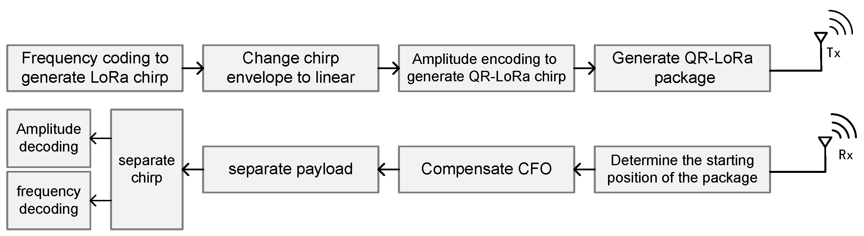
3.1. System Overview

The system overview of QR−LoRa is shown in Figure 4, including the transmitting and receiving modules.
Tx. First, the transmitter generates a standard LoRa chirp with the frequency encoded F 0 . Then, a ramp signal with the amplitude encoded T 0 is generated. They are multiplied to form a QR−LoRa chirp. We organize the QR−LoRa package according to the LPWAN protocol.
Rx. The receiver first identifies the QR−LoRa packet from the noisy received signal based on the Start-of-Frame Delimiter (SFD). To highlight the features of SFD, we make the envelope of d o w n c h i r p constituting SFD constant at 1. Then, the receiver determines the starting position of the data packet through the cross-correlation operation and separates the data packet. Next, Carrier Frequency Offset (CFO) compensation is performed on the separated data packets by leveraging the preamble. Finally, each chirp is read from the payload of the packet.
The demodulation of QR−LoRa includes two steps: first, frequency decoding, and then amplitude decoding. The traditional dechirp is adopted to perform frequency demodulation. For the amplitude demodulation, first, the envelope of QR−LoRa is extracted. Then the differential operation is performed on the envelope to achieve the exact amplitude jump position, which carries the amplitude-encoded information.

3.2. Joint Frequency-Amplitude Modulation

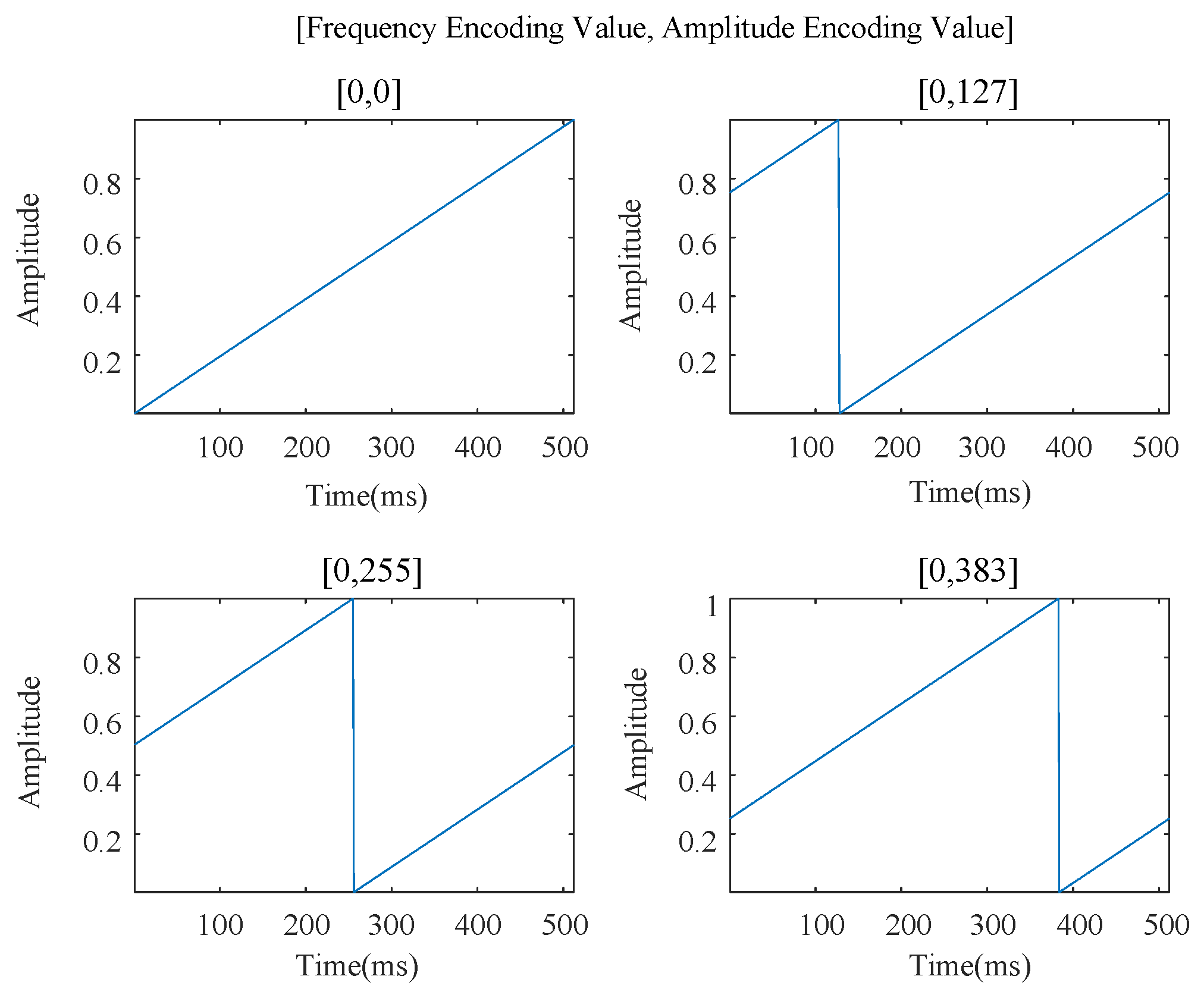
3.2.1. QR−LoRa Symbols

A QR−LoRa chirp can be expressed as
s F 0 t = e j 2 π B W T 1 2 t 2 + F 0 B W t B W 2 t , 0 t < T F 0 B W e j 2 π B W T 1 2 t 2 T t + F 0 B W t B W 2 t , T F 0 B W t < T
Then, we perform a cyclic right-shift of T 0 on a ramp signal, which can be written as
A t = 1 T t + T T 0 , 0 t < T 0 1 T t T 0 , T 0 t < T
Multiplying A t with s F 0 t , we obtain the QR−LoRa chirp with the amplitude encoding value T 0 and the frequency encoding value F 0 , which can be given as
s F 0 , T 0 t = A t s F 0 t
Since there are two discontinuity points, which are the maximum and minimum of the envelope, we segment the signal into three parts to represent it, respectively. Assuming T 0 < T F 0 B W , the complete expression of QR−LoRa chirp is given as follows
s F 0 , T 0 t = 1 T t + T T 0 e j 2 π B W T 1 2 t 2 + F 0 B W t B W 2 t , 0 t < T 0 1 T t T 0 e j 2 π B W T 1 2 t 2 + F 0 B W t B W 2 t , T 0 t < T F 0 B W 1 T t T 0 e j 2 π B W T 1 2 t 2 T t + F 0 B W t B W 2 t , T F 0 B W t < T

3.2.2. QR−LoRa Packages

The QR−LoRa data packet structure is consistent with the standard LoRa and is composed of four parts: the pilot sequence, a short sync word, SFD, and payload. First of all, its pilot sequence consists of eight upchirps. The pilot sequence is followed by a short sync word with two upchirps. This is followed by the SFD consisting of 2.25 downchirps. Then, a complete preamble is formed. Following the preamble is a variable-length payload that contains the specific information sent by the user.

3.3. Joint Frequency-Amplitude Demodulation

3.3.1. Frequency Dimension Demodulation

The QR−LoRa frequency demodulation is the same as the standard LoRa. First, we multiply s F 0 , T 0 t by d o w n c h i r p t = e j 2 π B W 2 t 1 2 B W T t 2 , 0 t T , obtaining
s r x ( t ) = s F 0 , T 0 t d o w n c h i r p t = 1 T t + T T 0 e j 2 π F 0 T t , 0 t < T 0 1 T t T 0 e j 2 π F 0 T t , T 0 t < T F 0 B W 1 T t T 0 e j 2 π B W + F 0 T t , T F 0 B W t < T
The duration of one chirp is 2 S F B W seconds. Sampling s r x ( t ) with f s = B W , we obtain T 0 = n 0 B W , where n 0 is the corresponding sampling point after T 0 is digitized. The sampled received signal can be expressed as
s r x n = s r x n B W = n n 0 2 S F + 1 e j 2 π F 0 2 S F n , 0 n n 0 1 n n 0 2 S F e j 2 π F 0 2 S F n , n 0 n 2 S F 1
Next, a Discrete Fourier Transform (DFT) is performed on the signal s r x n , yielding
S r x m = D F T [ s r x n ] = n = 0 2 S F 1 s r x n W 2 S F m n = n = 0 n 0 1 2 S F + n n 0 2 S F e j 2 π n F 0 m 2 S F + n = n 0 2 S F 1 n n 0 2 S F e j 2 π n F 0 m 2 S F = 2 S F 1 2 , m = F 0 1 e j 2 π F 0 m 2 S F n 1 , m = e l s e
Note that W 2 S F m n = e j 2 π n m 2 S F . When m = e l s e , we obtain
S r x m = 1 2 sin π F 0 m 2 S F
Equation (12) demonstrates that when demodulating the QR−LoRa symbol, almost all the energy will converge into a single peak with a height of 2 S F 1 2 at m = F 0 while the energy at other frequencies will rapidly decay to close to 0. Accordingly, the receiver demodulates the frequency encoded value according to the position of the spectrum peak, as shown in Figure 5.

3.3.2. Amplitude Dimension Demodulation

A t is sampled at f s = B W , and its discrete sequence can be represented by
A n = n n 0 2 S F + 1 , 0 n n 0 1 n n 0 2 S F , n 0 n 2 S F 1
Then, a differential operation is performed on the sequence A ( n ) to achieve the amplitude-encoded value,
diff A n = 2 S F 1 2 S F 1 , n = n 0 1 2 S F 0 , n = e l s e
Figure 6 depicts the difference operation result, where the expected peak with an amplitude of 1 appears at the amplitude jump point, the 256th sampling point.

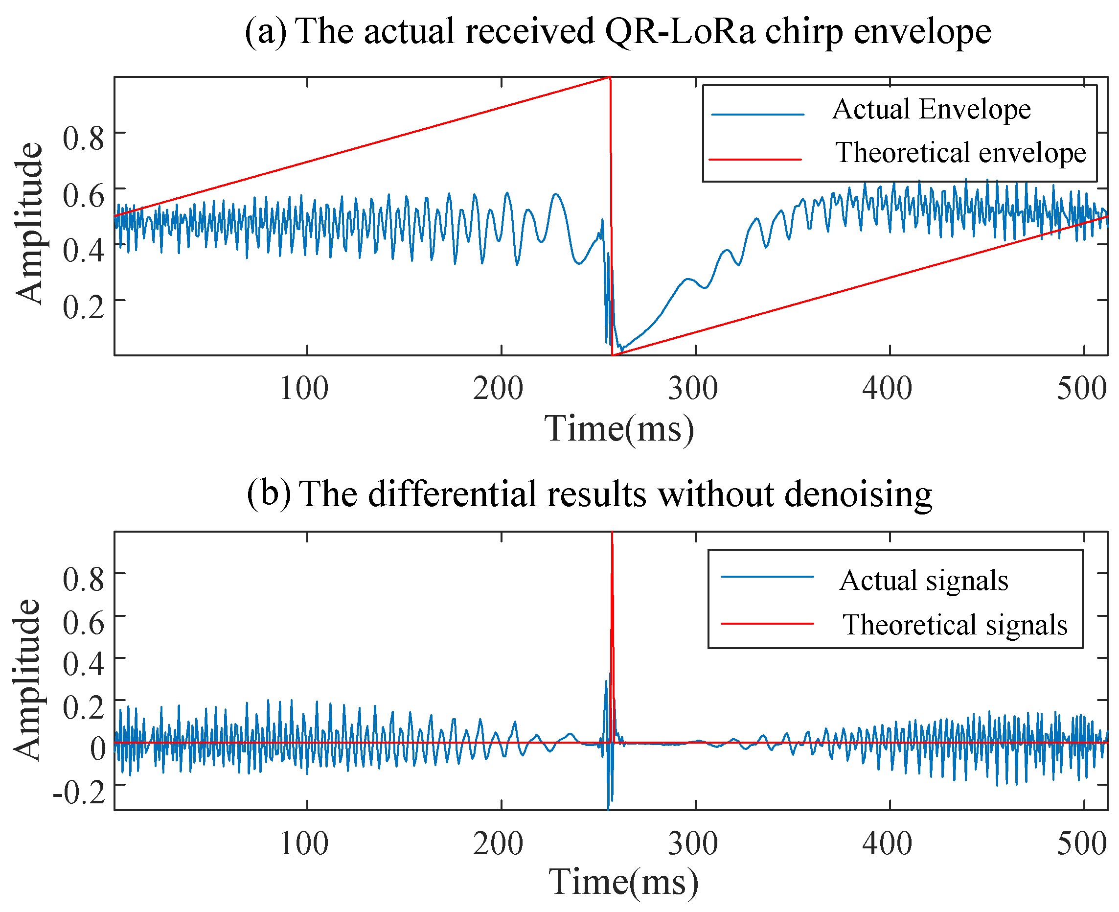
3.4. Denoising Algorithm

Due to the randomness, dynamics and multipath of the channel, the envelope of the QR−LoRa chirp received in the practical propagation environment suffers severe fast fading, and will be contaminated by noise, shown as in Figure 7a. Correspondingly, the difference operation result will present multiple peaks instead of only one perfect peak at the amplitude encoded position, shown as in Figure 7b. There are two problems with the practical envelope compared with the perfect envelope: (1) The perfect linear characteristic disappears; instead, there are nonlinear distortions that occur with the envelope. (2) The envelope is no longer smooth and presents rapid disturbance. The mentioned distortion and rapid disturbance enable the difference result to exhibit false peaks at multiple sampling points, as shown in Figure 7b. Even worse, some false peaks are stronger than the expected peak. As a result, the expected peak cannot be detected.
To this end, we propose an envelope denoising algorithm. The main idea is based on the following observations: in the amplitude demodulation, the position of the expected peak in diff A n should be consistent with the amplitude jump point, while at other positions the variation in the envelope sequence A ( n ) should be as stable as possible. Through observing, the mentioned distortion and rapid disturbance do not change the position of the expected peak, but only cause diff A n to produce extensive false peaks. Therefore, the goal of the denoising algorithm is to preserve the expected peak and suppress the extensive false peaks. Thus, we give the basic workflow of the envelope denoising algorithm as follows.
Each point in A ( n ) is compared with the previous one in turn. If the n t h sampling point is smaller than the ( n + 1 ) t h sampling point, the value of the n t h point is replaced with the average value of these two sampling points. Otherwise, it keeps its own value. The pseudo code of the denoising algorithm is presented in Algorithm 1. By means of raising valleys, the fluctuation on the envelope is eliminated; meanwhile, the maximum descent gradient is completely preserved. An example of Algorithm 1 is shown in Figure 8.
Algorithm 1 Envelope Denoising Algorithm
  • Input: A(n), count ← 1
  • Output: B(n)
  • while count <= 15        %set times
  •     for i ← 1 to n
  •        if A(i) < A(i + 1)
  •              B(i) ← [A(i) + A(i + 1)]/2;
  •        else
  •              B(i) ← A(i);
  •        end
  •     end
  •     countcount + 1
  • end

3.5. Minimum Aided Decoding Algorithm (MADA)

If the noise occurs at the position of the amplitude jump point, as shown in Figure 9a, it still brings severe interferences to the amplitude demodulation even if processed by the denoising algorithm, as shown in Figure 9b.
To address the problem, we propose a Minimum Aided Decoding Algorithm (MADA) based on the fact that the position of the amplitude jump point is also the minimum value of A ( n ) . Therefore, we can calibrate the denoising results by searching for the minimum value of A ( n ) . A simulation result shows that MADA can achieve about 20% improvements in Bit Error Rate (BER) performance, as shown in Figure 10.

4. Theoretical Analysis

4.1. Data Rate

A LoRa chirp can carry S F bits of information through frequency modulation, and its duration is T = 2 S F B W , then the bit rate of LoRa is
R b L = S F T = S F 2 S F B W
The basic unit of the cyclic right-shift operation is one sampling point. Therefore, the amount of information carried by amplitude modulation is dependent on the sampling rate f s . The duration of a QR−LoRa chirp is T = 2 S F B W , then the sampling points 2 S F B W · f s can be obtained. That means the amplitude modulation can carry log 2 2 S F B W · f s bit information. Thus, the bit rate of QR−LoRa is obtained as
R b Q R = B W 2 S F S F + log 2 2 S F B W · f s
According to the Nyquist–Shannon Sampling Theorem, Inter Symbol Interference (ISI) will not occur only when the sampling frequency f s 2 f H = B W . Substitute log 2 2 S F B W · f s log 2 2 S F = S F into Equation (16), then we have
R b Q R 2 S F 2 S F B W = 2 R b L
It can be seen that the bit rate of the QR−LoRa chirp can be doubled at least compared with the conventional LoRa.

4.2. QR−LoRa Chirp Energy

Intuitively, changing the envelope will have an influence on the energy. Thus, we evaluate the energy of the QR−LoRa chirp.
Let the slope of the envelope of a QR−LoRa chirp be μ , and A ( t ) can be represented as A ( t ) = μ t T , 0 t < T . Then, the energy can be calculated as
E Q R , μ = 0 T μ T t 2 d t = μ 2 3 T
Likely, the energy of a LoRa chirp is given as
E L = T
Obviously, the energy of a QR−LoRa chirp is μ 2 3 times that of a LoRa chirp. If the envelope slope is set to μ 3 , the energy of a QR−LoRa chirp will be the same as the LoRa chirp. We define the energy efficiency of the symbol as
ρ = h E
where h is the height of the peak of the amplitude spectrum. Accordingly, the energy efficiency of LoRa chirp is defined as
ρ L = 2 S F T
The energy efficiency of the QR−LoRa chirp with envelope slope μ can be derived by
ρ Q R , μ = h Q R , μ E Q R , μ = 3 2 μ · 2 S F 1 T
where h Q R , μ = μ · 2 S F 1 2 . We can see that when the slope μ 3 2 · 2 S F 1 2 S F 3 2 , the energy efficiency of a QR−LoRa chirp will not be lower than that of a LoRa chirp.
Let μ = 1 , we have
E Q R = T 3 = 1 3 E L
ρ Q R = 3 2 · 2 S F 1 T 3 2 ρ L
In summary, QR−LoRa can reduce energy consumption and improve energy efficiency compared with the conventional LoRa.

4.3. Receiving Sensitivity

Although QR−LoRa can achieve comprehensive data rate improvement by frequency and amplitude cooperative modulation, there is still a gap in the receiving sensitivity. The frequency demodulation maintains the excellent anti-noise performance of LoRa. However, limited by the inherent properties of radio propagation, the information transmission in the amplitude dimension is completely destroyed by the noise and interference when SNR < 0 dB. Only when the SNR at the receiver is higher than 10 dB can the amplitude dimension of QR−LoRa transmit information robustly. Thus, we design QR−LoRa to work in two modes according to the current SNR to balance the two modulation methods. On the one hand, the amplitude and frequency are jointly utilized to transmit information in medium- and high-SNR scenarios. On the other hand, only the frequency is used to transmit information in the low or extremely low SNR scenarios.
Furthermore, phase noise is another factor that impacts the demodulation performance of QR−LoRa. Hajimiri and Lee [27] claimed that the phase errors are caused by fluctuations in the noise amplitude around the zero crossings of the local oscillator. It may lead to Carrier Frequency Offset (CFO) and Sampling Time Offset (STO) in amplitude decoding. Since the known and fixed pattern of the preamble and SFD allows for precise frequency offset estimation and timing synchronization, Tong et al. leverage preamble-based CFO and STO cancellation for robust LoRa demodulation in low SNR environments [28]. Likewise, we adopt the preamble of a LoRa chirp and its SFD to calibrate the CFO and STO.
A qualitative vulnerability analysis will be performed in our future work to explore the potential mitigation strategies, such as adaptive phase error correction or optimized oscillator designs. This analysis will complement the dual-mode operation strategy to further enhance system robustness across diverse channel conditions.

5. Evaluations

We choose Bit Rate (BR) and Bit Error Rate (BER) as the metrics to examine QR−LoRa basic performance for communication effectiveness and reliability. In order to demonstrate the advantages of QR−LoRa, we take the conventional LoRa and ICS-LoRa as the benchmark.

5.1. Implementation

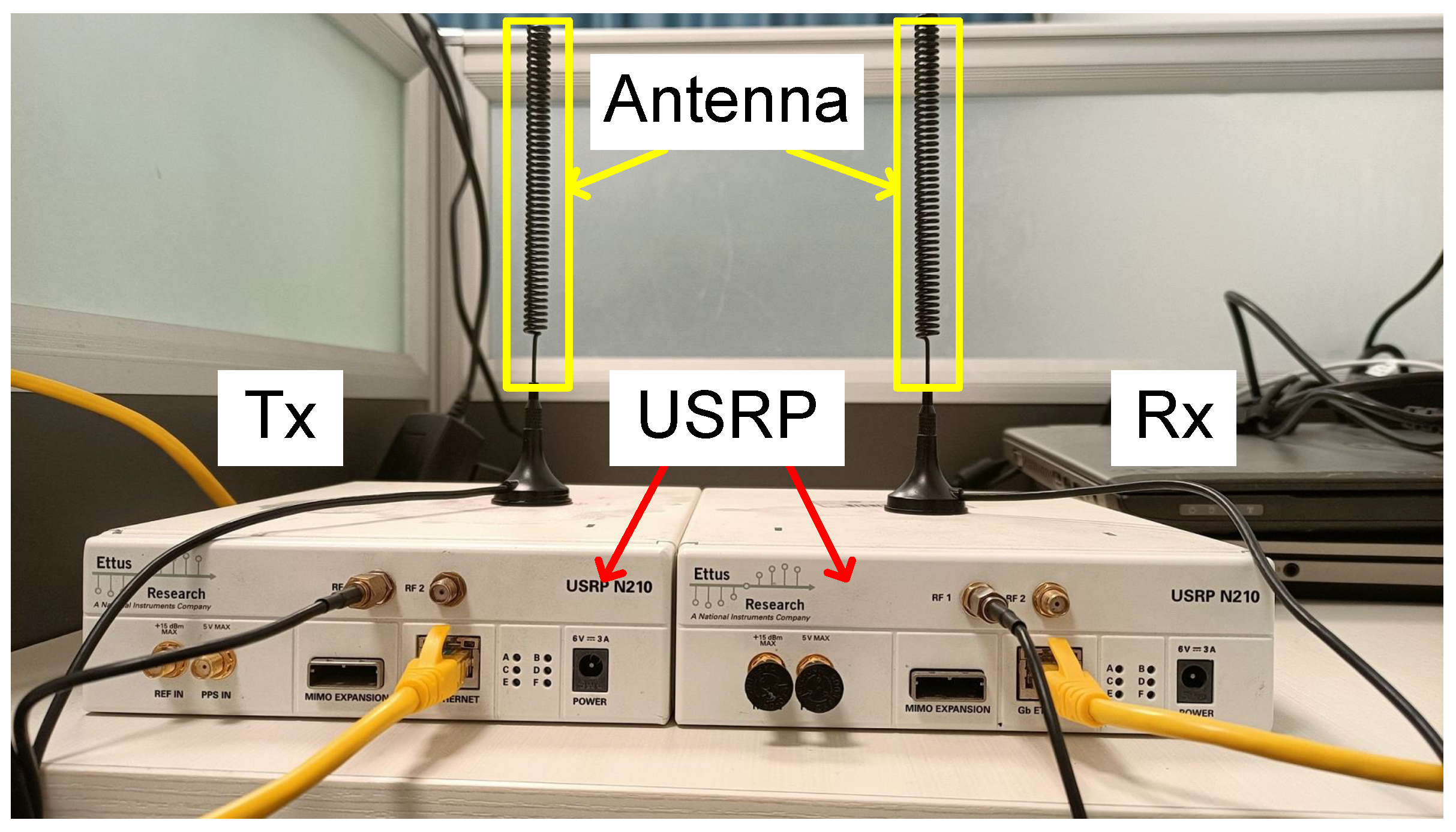
5.1.1. Software and Hardware Platform

We implement QR−LoRa on the Software-Defined Radio (SDR) USRP N210 equipped with a UBX daughter board. The transmitter and receiver operate in the unlicensed 433.92 MHz ISM band. The standard transmit power of USRP N210 is 15 dBm. The Tx/Rx antennas are a pair of circularly polarized helical antennas, which have 8 dBi gain, as shown in Figure 11. During the experiments, each packet of QR−LoRa consists of 10 upchirp, 2.25 downchirp and 17 QR−LoRa chirp. Furthermore, the parameters are configured as SF = 7, BW = 250 KHz and f s = 1 MHz.

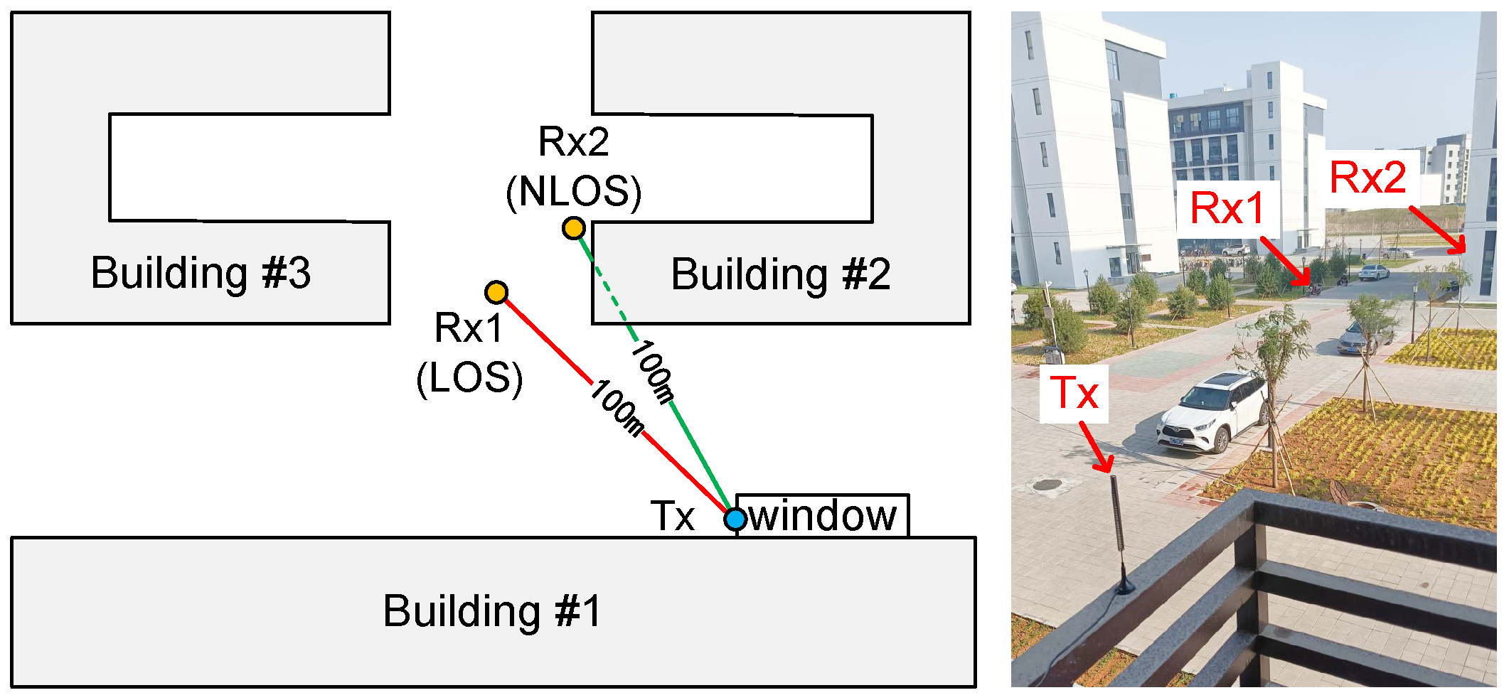
5.1.2. Experiment Setups and Plans

The actual environmental noise in the wireless communication scenario is a random variable. Even if the transmit power is adjustable, it is hard to obtain the real SNR at the receiver. Therefore, we conduct a distance-driven evaluation for the QR−LoRa prototype system. Specifically, we fix the location of the transmitter and perform the test by moving the receiver over different distances. According to the free space path loss model [29], if the transmit power is fixed, the received SNR decreases with the increase in the propagation distance. Hence, we examine the BR and BER performance of QR−LoRa with different propagation distances instead of the SNR, which is more practical. The experiments are conducted in outdoor environments, involving the Light of Sight (LOS) propagation and Non-Light of Sight (NLOS) propagation. The floor plan is depicted in Figure 12. It is noted that Rx is not set behind or in the building, which is not the complete NLOS propagation, because the amplitude of the QR−LoRa chirp is sensitive to the noise and interference in the environment.

5.2. Evaluation Results

In this section, we conduct extensive experiments to evaluate the performance of QR−LoRa.

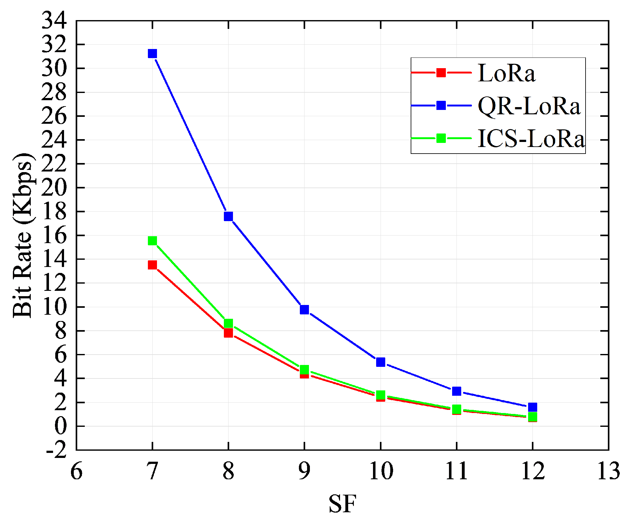
5.2.1. Bit Rate Performance

a.
BR vs. SF, when distance = 100 m
First, we evaluate the BR performance with different SFs. In order to reveal the advantages of the QR−LoRa, we chose an open outdoor field(LOS scenario). The distance between the transceivers is 100 m. According to different values of SF, the BR curve is presented in Figure 13. With the increase in the spreading factor, the BR curves of the conventional LoRa, ICS-LoRa and QR−LoRa show a downward trend. QR−LoRa always outperforms the others, especially twice as much as the conventional LoRa. We conclude that the bit rate of LoRa can be effectively improved by adding amplitude modulation.
b.
BR vs. Distance, when SF = 7
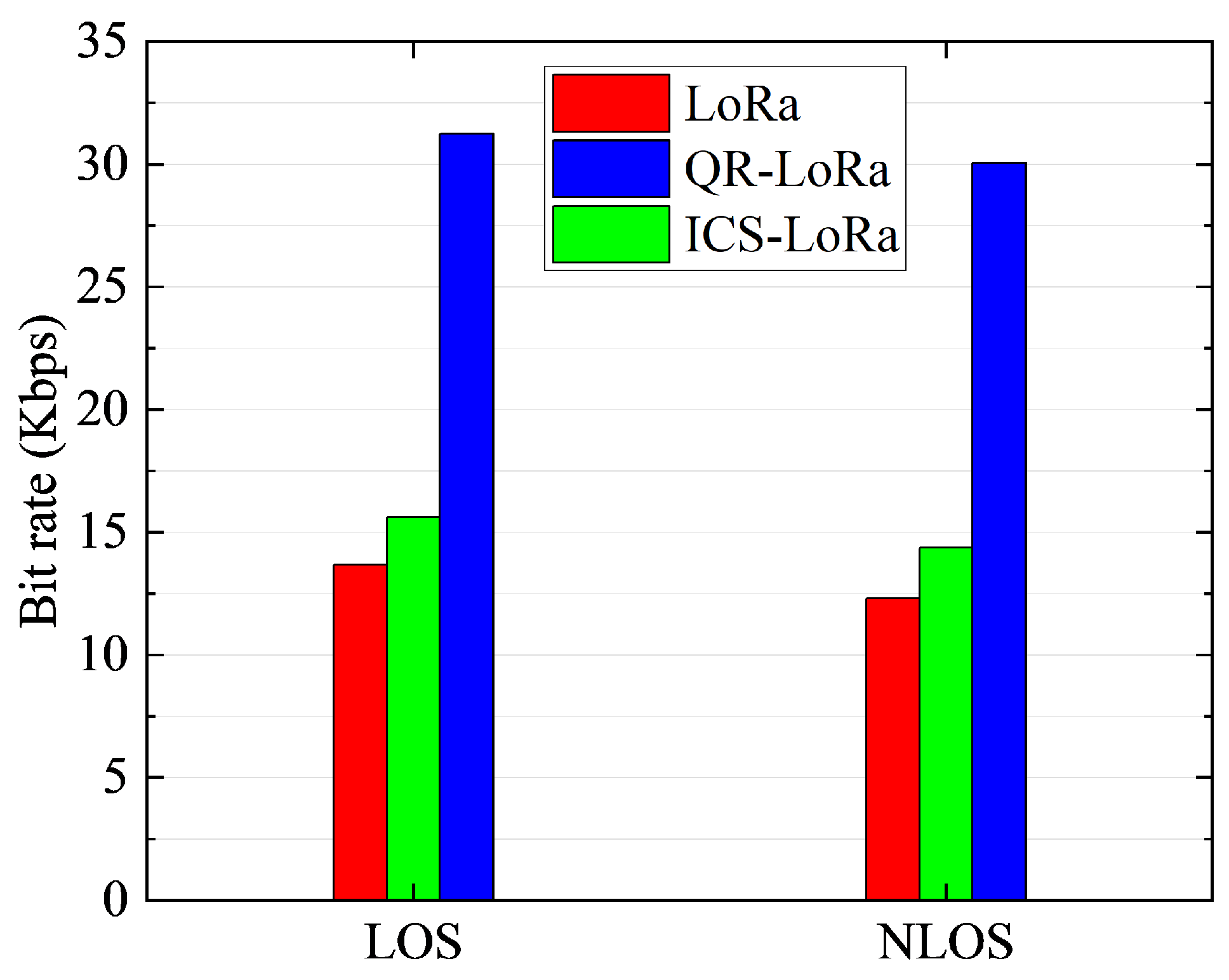
Figure 14 depicts the BR curves with different propagation distances. We know from the analysis that the performance of QR−LoRa in the amplitude dimension is limited by the SNR. When the SNR is lower than 0 dB, the amplitude demodulation will completely fail. Therefore, we set the maximum distance of the transceiver to 150 m, and the test was conducted in a line-of-sight (LOS) scenario. As observed from the experimental results shown in Figure 14, the BR is almost stationary when the propagation distance changes from 10 m to 150 m. Because there is nearly no packet loss in the 150 m distance, QR−LoRa has above 30 Kbps BR, significantly higher than the conventional LoRa and ICS−LoRa.
c.
BR vs. LOS and NLOS, when distance = 100 m, SF = 7
In order to further evaluate the anti-multipath ability of QR−LoRa, we verify the impact of LOS and NLOS propagation on the BR performance in an outdoor environment. The experimental results are shown in Figure 15. It can be found that the BR of LoRa, ICS-LoRa, and QR−LoRa in the NLOS propagation are 12.5 Kbps, 16.2 Kbps, and 27.5 Kbps, respectively, and all of them reduce to different degrees compared with the LOS propagation. The reason is around 20 dB descending in the received signal strength caused by the blockage of the building in the NLOS propagation.

5.2.2. BER Performance

a.
BER vs. SF, when distance = 100 m
This subsection will evaluate the BER performance of QR−LoRa. As well, the conventional LoRa is involved for comparison. The relationship between BER and SF is illustrated in Figure 16, where the red solid line represents the conventional LoRa, the blue solid line is the QR−LoRa frequency demodulation, and the blue dashed line indicates the QR−LoRa amplitude demodulation. As seen in Figure 16, when the communication distance is 100 m in the line-of-sight (LOS) scenario, LoRa and QR−LoRa frequency demodulation work robustly and their BER is lower than 10 4 . With the growth of SF, the BER further decreases. Meanwhile, the BER of QR−LoRa amplitude demodulation is below 10 3 , exhibiting a fluctuating state with the increase in SF. It is caused by the inherent characteristic of amplitude modulation. Moreover, the randomness of the wireless channel introduces the BER fluctuations of the amplitude modulation.
b.
BER vs. Distance, when SF = 7
Figure 17 presents the relationship between BER and the communication distance. We compare the BER performance between QR−LoRa and the conventional LoRa with different distances (10 m, 25 m, 50 m, 75 m, 100 m, 125 m and 150 m). According to the experimental results, the frequency demodulation of QR−LoRa has a similar performance to the conventional LoRa in the communication range of 150 m, mainly in the line−of−sight (LOS) scenario. Both of their BERs are below the 10 4 level. The amplitude modulation of QR−LoRa can ensure the accuracy of demodulation within 100 m. Obviously, further improving the communication range of amplitude modulation should be a focus of our future work.
c.
BER vs. LOS and NLOS, when distance = 100 m, SF = 7
We also evaluate the BER performance in LOS and NLOS propagation scenarios. The evaluation results are shown in Figure 18. We use red, orange and blue to represent the conventional LoRa, the frequency demodulation of QR−LoRa and the amplitude demodulation of QR−LoRa separately. In the LOS scenario, the BER of LoRa and QR−LoRa frequency modulation are both lower than 10 4 , but QR−LoRa frequency modulation performs better. The amplitude modulation BER of QR−LoRa is about 10 3 due to the 100 m propagation distance. In the NLOS scenario, the BER performs worse than that in the LOS scenario, which increases by around half an order of magnitude. Although the block of the building reduces the received signal strength and leads to the received SNR descending, we know from the analysis in Section 4.2 that the efficiency of QR−LoRa frequency demodulation is superior to the conventional LoRa. As expected, QR−LoRa demonstrates the quality reliability in the NLOS scenario compared with the conventional LoRa.

5.3. Compatibility with Existing LoRa System

To enable the proposed scheme to be commercially feasible, we explore the compatibility with the commercial LoRaWAN device, such as the commercial off-the-shelf LoRa node equipped with a Semtech SX1276RF1JAS. Inspired by previous work [5], we can transform the existing LoRa node into a QR−LoRa node by plugging in an external expansion board, as shown in Figure 19.
The expansion board consists of an MCU, a switch, a passive surface acoustic wave filter (SAW Filter) [30], and an envelope detector [31]. The SAW filter is a narrowband bandpass filter with a center frequency of 433.92 MHz and a passband bandwidth of 500 kHz. The red dotted line in Figure 19 denotes the generation route of the QR−LoRa chirp, the blue dotted line represents the frequency demodulation route of the QR−LoRa signal and the green dotted line shows its amplitude demodulation route.
For the transmitter, as in the red dotted line shown in Figure 19, the MCU sends instructions to the LoRa node to generate a standard LoRa chirp. Then, the MCU controls the switch to the Passive SAW Filter branch, where the standard LoRa chirp is transformed into a QR−LoRa chirp through the Passive SAW Filter. For the receiver, as in the blue and green dotted lines shown in Figure 19, the QR−LoRa signal received by the antenna is divided into two parts, one is directly fed into the LoRa node through the RF switch controlled by the MCU for standard LoRa frequency demodulation. On the other hand, the QR−LoRa amplitude demodulation process is as follows: (1) The envelope detector extracts the envelope of the received QR−LoRa signal and sends it to the MCU. (2) The MCU samples the envelope and performs amplitude demodulation through differential algorithm.
It should be noted that the function of the Passive SAW Filter is to realize the mapping from frequency modulation to amplitude modulation. Reference [5] utilizes the steep transition band of the Passive SAW Filter so that the amplitude of the LoRa chirp passing through the critical band varies with the LoRa chirp frequency. This characteristic is exactly in line with the QR−LoRa amplitude modulation requirements. For the detailed working principle of the Passive SAW Filter, please refer to [5].
In summary, the QR−LoRa node is compatible with a LoRa node through an external expansion board. The Passive SAW Filter, envelope detector and RF switch in the expansion board are passive devices and the MCU can use the ultra-low power Apollo2 (Reference [5] evaluates that its power consumption is only 19.6 uW). Therefore, the power consumption of the expansion board will not increase the power consumption cost too much. In addition, the above-mentioned passive devices are small in size and low in price, which makes QR−LoRa a commercial prospect.
The detailed design and implementation compatible with LoRa commercial devices is a very interesting and meaningful task, which we view as part of our future work. The pulse-encoded transition (PET) technique and stacked-FET switches discussed in [32] offer low-loss, high-power handling capabilities suitable for the commercialization of QR−LoRa. In our future work, we aim to implement these techniques to optimize ACLR and bandwidth for better LoRa compatibility. Additionally, we plan to explore the impact of different pulse shapes, such as raised cosine, as part of the ongoing improvements in our research.

5.4. Comparison with Different Methods

To validate the effectiveness of the proposed method, we compare its Bit Error Rate (BER) and bit rate with state-of-the-art benchmarks. The experimental configuration is fixed at spreading factor (SF = 7), bandwidth (BW = 250 kHz), and signal-to-noise ratio (SNR = 5 dB). The comparison methods include LoRa, SSK-LoRa, PSK-LoRa, and FBI-LoRa. The bit rate of SSK-LoRa is calculated as follows:
R b = S F + 1 2 S F B W
For PSK-LoRa, the bit rate is given by the following:
R b = S F + log 2 M 2 S F B W
where M is the order of PSK. Based on the experimental parameters from the PSK-LoRa reference, M = 16 is selected. The bit rate for FBI-LoRa is computed as follows:
R b = N t o t T s y m
where N t o t is to calculate the number of information bits carried by each symbol, T s y m is the duration of one symbol. This study employs FBI-LoRa Scheme 2 for comparison. As evidenced by the results in Table 1, QR−LoRa demonstrates superior performance in both bit rate and Bit Error Rate (BER), achieving a maximum bit rate of 31.25 kbps and a minimum BER of 10 5 . Compared with LoRa, SSK-LoRa, and PSK-LoRa, QR−LoRa delivers up to a 17.58 kbps higher bit rate and up to 5.99 × 10 3 lower BER. Implementation requires only an additional memory module for amplitude mapping storage, maintaining a hardware cost comparable to conventional LoRa systems, as shown in Table 1.

6. Conclusions

We present the design, implementation and evaluation of QR−LoRa, which is a novel PHY-layer scheme that leverages the joint frequency-amplitude modulation to improve the bit rate of LoRa transmissions. On top of the frequency-modulated information of traditional LoRa PHY, QR−LoRa also modulates another dimension of data in the amplitude domain simultaneously. We prototype QR−LoRa on the USRP N210 and conduct extensive evaluations. We believe QR−LoRa represents a significant step in a line of work that could improve the bit rate gain by a factor of 2 compared with existing LoRa devices.

Author Contributions

Conceptualization, G.T. and Z.Z.; Methodology, G.T.; Software, J.W.; Validation, G.T., Z.Z. and L.W.; Formal analysis, G.T.; Investigation, G.T.; Resources, C.Z.; Data curation, N.J.; Writing—review and editing, all authors. All authors have read and agreed to the published version of the manuscript.

Funding

This research was funded by the National Natural Science Foundation of China [Grant No. 62472369], the Natural Science Foundation of Hebei Province [Grant No. F2022203045], the Beijing Natural Science Foundation [Grant No. L222004], the Hebei Provincial Science and Technology Research and Development Program [Grant No. 236Z0801G, 22567637H], and the Hebei Key Laboratory Project [Grant No. 202250701010046, 22567637H].

Data Availability Statement

Data sharing is not applicable to this article as the study did not generate new data and the used data are subject to commercial confidentiality agreements.

Acknowledgments

We would like to express heartfelt gratitude to the research team at Yanshan University’s School of Information Science and Engineering, whose collaborative discussions and technical support were instrumental in the development of this work. Special thanks are extended to the Hebei Key Laboratory of Information Transmission and Signal Processing for providing the experimental facilities and academic environment that enabled the implementation and validation of QR−LoRa.Finally, we appreciate the constructive feedback from reviewers, which helped refine the manuscript and strengthen the technical contributions described herein.

Conflicts of Interest

All authors disclosed no relevant relationships.

References

  1. Li, C.; Cao, Z. Lora networking techniques for large-scale and long-term iot: A down-to-top survey. ACM Comput. Surv. (CSUR) 2022, 55, 52. [Google Scholar] [CrossRef]
  2. Sinha, R.S.; Wei, Y.; Hwang, S.H. A survey on LPWA technology: LoRa and NB-IoT. ICT Express 2017, 3, 14–21. [Google Scholar] [CrossRef]
  3. Vejlgaard, B.; Lauridsen, M.; Nguyen, H.; Kovács, I.Z.; Mogensen, P.; Sorensen, M. Coverage and capacity analysis of sigfox, lora, gprs, and nb-iot. In Proceedings of the 2017 IEEE 85th vehicular technology conference (VTC Spring), Sydney, Australia, 4–7 June 2017; IEEE: Piscataway, NJ, USA, 2017; pp. 1–5. [Google Scholar]
  4. Liando, J.C.; Gamage, A.; Tengourtius, A.W.; Li, M. Known and unknown facts of LoRa: Experiences from a large-scale measurement study. ACM Trans. Sens. Netw. (TOSN) 2019, 15, 16. [Google Scholar] [CrossRef]
  5. Guo, X.; Shangguan, L.; He, Y.; Jing, N.; Zhang, J.; Jiang, H.; Liu, Y. Saiyan: Design and Implementation of a Low-power Demodulator for LoRa Backscatter Systems. In Proceedings of the 19th USENIX Symposium on Networked Systems Design and Implementation (NSDI 22), Renton, WA, USA, 4–6 April 2022; pp. 437–451. [Google Scholar]
  6. Guo, X.; Shangguan, L.; He, Y.; Zhang, J.; Jiang, H.; Siddiqi, A.A.; Liu, Y. Aloba: Rethinking ON-OFF keying modulation for ambient LoRa backscatter. In Proceedings of the 18th Conference on Embedded Networked Sensor Systems, Virtual, 16–19 November 2020; pp. 192–204. [Google Scholar]
  7. Chen, G.; Dong, W.; Lv, J. Lofi: Enabling 2.4 ghz lora and wifi coexistence by detecting extremely weak signals. In Proceedings of the IEEE INFOCOM 2021—IEEE Conference on Computer Communications, Vancouver, BC, Canada, 10–13 May 2021; IEEE: Piscataway, NJ, USA, 2021; pp. 1–10. [Google Scholar]
  8. Demeslay, C.; Rostaing, P.; Gautier, R. Theoretical Performance of LoRa System in Multipath and Interference Channels. IEEE Internet Things J. 2021, 9, 6830–6843. [Google Scholar] [CrossRef]
  9. Gamage, A.; Liando, J.C.; Gu, C.; Tan, R.; Li, M. Lmac: Efficient carrier-sense multiple access for lora. In Proceedings of the 26th Annual International Conference on Mobile Computing and Networking, London, UK, 21–25 September 2020; pp. 1–13. [Google Scholar]
  10. Li, C.; Ren, Y.; Tong, S.; Siam, S.I.; Zhang, M.; Wang, J.; Liu, Y.; Cao, Z. ChirpTransformer: Versatile LoRa encoding for low-power wide-area IoT. In Proceedings of the 22nd Annual International Conference on Mobile Systems, Applications and Services, Tokyo, Japan, 3–7 June 2024; pp. 479–491. [Google Scholar]
  11. Li, C.; Guo, X.; Shangguan, L.; Cao, Z.; Jamieson, K. {CurvingLoRa} to boost {LoRa} network throughput via concurrent transmission. In Proceedings of the 19th USENIX Symposium on Networked Systems Design and Implementation (NSDI 22), Renton, WA, USA, 4–6 April 2022; pp. 879–895. [Google Scholar]
  12. Tong, S.; Xu, Z.; Wang, J. Colora: Enabling multi-packet reception in lora. In Proceedings of the IEEE INFOCOM 2020—IEEE Conference on Computer Communications, Toronto, ON, Canada, 6–9 July 2020; IEEE: Piscataway, NJ, USA, 2020; pp. 2303–2311. [Google Scholar]
  13. Elshabrawy, T.; Robert, J. Interleaved chirp spreading LoRa-based modulation. IEEE Internet Things J. 2019, 6, 3855–3863. [Google Scholar] [CrossRef]
  14. Hanif, M.; Nguyen, H.H. Slope-shift keying LoRa-based modulation. IEEE Internet Things J. 2020, 8, 211–221. [Google Scholar] [CrossRef]
  15. Bomfin, R.; Chafii, M.; Fettweis, G. A novel modulation for IoT: PSK-LoRa. In Proceedings of the 2019 IEEE 89th Vehicular Technology Conference (VTC2019-Spring), Kuala Lumpur, Malaysia, 28 April–1 May 2019; IEEE: Piscataway, NJ, USA, 2019; pp. 1–5. [Google Scholar]
  16. Yu, Q.; Wang, H.; Lu, Z.; An, S. Group-based CSS modulation: A novel enhancement to LoRa physical layer. IEEE Wirel. Commun. Lett. 2022, 11, 660–664. [Google Scholar] [CrossRef]
  17. An, S.; Wang, H.; Sun, Y.; Lu, Z.; Yu, Q. Time domain multiplexed LoRa modulation waveform design for IoT communication. IEEE Commun. Lett. 2022, 26, 838–842. [Google Scholar] [CrossRef]
  18. Azim, A.W.; Bazzi, A.; Fatima, M.; Shubair, R.; Chafii, M. Dual-mode time domain multiplexed chirp spread spectrum. IEEE Trans. Veh. Technol. 2023, 72, 16086–16097. [Google Scholar] [CrossRef]
  19. Ma, H.; Fang, Y.; Cai, G.; Han, G.; Li, Y. A New Frequency-Bin-Index LoRa System for High-Data-Rate Transmission: Design and Performance Analysis. IEEE Internet Things J. 2021, 9, 12515–12528. [Google Scholar] [CrossRef]
  20. Azim, A.W.; Bazzi, A.; Bomfin, R.; Shubair, R.; Chafii, M. Layered chirp spread spectrum modulations for LPWANs. IEEE Trans. Commun. 2023, 72, 1671–1687. [Google Scholar] [CrossRef]
  21. Zhang, Z. ZChirp: Speeding Up LPWANs by Combining the Chirp with Binary Sequences. In Proceedings of the 2024 21st Annual IEEE International Conference on Sensing, Communication, and Networking (SECON), Phoenix, AZ, USA, 2–4 December 2024; pp. 1–9. [Google Scholar]
  22. Lee, G.; Park, E.; Park, M.; Paek, J.; Bahk, S. BIC-LoRa: Bits in Chirp Shapes to Boost Throughput in LoRa. In Proceedings of the 2024 23rd ACM/IEEE International Conference on Information Processing in Sensor Networks (IPSN), Hong Kong, China, 13–16 May 2024; pp. 237–248. [Google Scholar]
  23. Vangelista, L.; Jechoux, B.; Canonici, J.X.; Zorzi, M. Golden modulation: A new and effective waveform for massive IoT. IEEE Trans. Commun. 2023, 72, 1938–1948. [Google Scholar] [CrossRef]
  24. Cao, C.; Zhai, S. A Scheme Using Up-chirp and Down-chirp for LoRa’s bit Synchronization and Carrier Restoration. In Proceedings of the 2020 IEEE 6th International Conference on Computer and Communications (ICCC), Chengdu, China, 11–14 December 2020; IEEE: Piscataway, NJ, USA, 2020; pp. 288–292. [Google Scholar]
  25. Ameloot, T.; Rogier, H.; Moeneclaey, M.; Van Torre, P. LoRa Signal Synchronization and Detection at Extremely Low Signal-to-Noise Ratios. IEEE Internet Things J. 2021, 9, 8869–8882. [Google Scholar] [CrossRef]
  26. Baddula, M.; Ray, B.; Chowdhury, M. Performance Evaluation of Aloha and CSMA for LoRaWAN Network. In Proceedings of the 2020 IEEE Asia-Pacific Conference on Computer Science and Data Engineering (CSDE), Gold Coast, Australia, 16–18 December 2020; IEEE: Piscataway, NJ, USA, 2020; pp. 1–6. [Google Scholar]
  27. Hajimiri, A.; Lee, T.H. A general theory of phase noise in electrical oscillators. IEEE J. Solid-State Circuits 1998, 33, 179–194. [Google Scholar] [CrossRef]
  28. Tong, S.; Wang, J.; Liu, Y. Combating packet collisions using non-stationary signal scaling in LPWANs. In Proceedings of the Proceedings of the 18th International Conference on Mobile Systems, Applications, and Services, Toronto, ON, Canada, 15–19 June 2020; pp. 234–246. [Google Scholar]
  29. Friis, H.T. A note on a simple transmission formula. Proc. IRE 1946, 34, 254–256. [Google Scholar] [CrossRef]
  30. Islam, T.; Mittal, U.; Nimal, A.; Sharma, M. Surface Acoustic Wave (SAW) vapour sensor using 70 MHz SAW oscillator. In Proceedings of the 2012 Sixth International Conference on Sensing Technology (ICST), West Bangal, India, 18–21 December 2012; IEEE: Piscataway, NJ, USA, 2012; pp. 112–114. [Google Scholar]
  31. Huang, X.; Dolmans, G.; De Groot, H.; Long, J.R. Noise and sensitivity in RF envelope detection receivers. IEEE Trans. Circuits Syst. II Express Briefs 2013, 60, 637–641. [Google Scholar] [CrossRef]
  32. Hill, C.; Hamza, A.; AlShammary, H.; Buckwalter, J.F. Watt-level, direct RF modulation in CMOS SOI with pulse-encoded transitions for adjacent channel leakage reduction. IEEE Trans. Microw. Theory Tech. 2019, 67, 5315–5328. [Google Scholar] [CrossRef]
Figure 1. QR−LoRa chirp envelopes with different amplitude encoded values.
Electronics 14 02687 g001
Figure 2. QR−LoRa symbols.
Electronics 14 02687 g002
Figure 3. Four QR−LoRa chirps with same frequency encoded value but different amplitude encoded values.
Electronics 14 02687 g003
Figure 4. System overview of QR−LoRa.
Electronics 14 02687 g004
Figure 5. The result of QR−LoRa chirp frequency demodulation.
Electronics 14 02687 g005
Figure 6. The result of the differential operation.
Electronics 14 02687 g006
Figure 7. QR−LoRa chirp envelope received in practical environment and its difference operation result.
Electronics 14 02687 g007
Figure 8. Before and after envelope denoising for A ( n ) .
Electronics 14 02687 g008
Figure 9. An example of the noise occurs at the position of the maximum descending gradient.
Electronics 14 02687 g009
Figure 10. Comparison of BER on the amplitude modulation before and after MADA.
Electronics 14 02687 g010
Figure 11. Hardware platform.
Electronics 14 02687 g011
Figure 12. Experiment settings and plans of the LOS propagation and NLOS propagation.
Electronics 14 02687 g012
Figure 13. BR vs. SF measured results.
Electronics 14 02687 g013
Figure 14. BR vs. distance measured results.
Electronics 14 02687 g014
Figure 15. BR measured results under LOS and NLOS conditions.
Electronics 14 02687 g015
Figure 16. BER vs. SF measured results.
Electronics 14 02687 g016
Figure 17. BER vs. distance measured results.
Electronics 14 02687 g017
Figure 18. BER measured results under LOS and NLOS conditions.
Electronics 14 02687 g018
Figure 19. QR−LoRa node.
Electronics 14 02687 g019
Table 1. PerformanceComparison of Different Methods.
MethodLoRaSSK-LoRaPSK-LoRaFBI-LoRaOurs
Bit Rate(kbps)13.6715.6321.4831.2531.25
BER 6 × 10 4 5 × 10 5 9 × 10 3 7 × 10 3 1 × 10 5
Hardware Cost$7\\\$10
Disclaimer/Publisher’s Note: The statements, opinions and data contained in all publications are solely those of the individual author(s) and contributor(s) and not of MDPI and/or the editor(s). MDPI and/or the editor(s) disclaim responsibility for any injury to people or property resulting from any ideas, methods, instructions or products referred to in the content.

