Abstract
In low-detectability application scenarios such as covert reconnaissance, wildlife behavior observation, and battlefield detection, antennas not only need to have wideband performance but also require good biomimetic camouflage characteristics. To address this issue, this article proposes a leaf-shaped biomimetic flexible wideband antenna. The design concept of the antenna is inspired by the symmetrical vein structure of aquifoliaceae leaves, incorporating vein-like slots into the radiation patch to form multiple inter-slot capacitances, which improves the high-frequency resonance behavior and expands the antenna’s operating bandwidth. In addition, the traditional rectangular grounding plane is replaced with a semi-elliptical shape, optimizing the electric field distribution between the feed line and the radiation part, thereby improving impedance matching. The measured results show that the leaf-shaped antenna achieves a relative bandwidth of 100% (2.4 GHz–7.1 GHz), with its operating frequency bands covering several common communication bands such as n41, n78, n79, and ISM 5.8 GHz, with a maximum gain of 5.4 dBi. Additionally, the leaf-shaped antenna has a good resemblance to the shape of aquifoliaceae leaves. The antenna’s performance remains relatively stable with bending radii of 40 mm, 50 mm, and 60 mm, demonstrating an important role in camouflage application scenarios.
1. Introduction
Natural organisms are the source of inspiration for human theoretical discoveries and technological inventions. As an interdisciplinary research field, biomimetics simulates the biological structures of nature, learns from biological principles, and achieves significant inventions and innovations [1,2,3,4]. Wideband miniaturized antennas have always been a research hotspot, especially in the field of communications [5,6,7,8,9]. In some special camouflage applications, such as battlefield radar reconnaissance, wildlife behavior observation, and security of key protected areas, antennas not only need to have excellent electromagnetic performance but should also possess a highly realistic biomimetic appearance [10,11,12,13]. The shape of biological organisms typically has its own unique characteristics, so it is essential to identify common shape and size features between the biological organism and the antenna structure and then integrate them into the design. This is the unique feature of this paper.
In recent years, research on biomimetic antennas has mainly been divided into two directions: functional biomimicry and morphological biomimicry [14,15]. The direction of morphological biomimicry is inspired by the external shape characteristics of biological organisms, using similar structures in antenna design to improve antenna performance. Reference [16] drew inspiration from the structure of moth antennae, applying biomimetic principles to reduce the radar cross-section of the antenna. Reference [17] drew on the structure of snowflakes, combining the Koch curve structure with the fractal concept of hexagonal snowflakes to achieve a high-gain antenna that operates simultaneously in three frequency bands: 2.38–2.90 GHz (20.3%), 3.35–3.85 GHz (14.1%), and 5.06–5.80 GHz (13.5%). Reference [18] drew on the fractal structure of leaves, extending the bandwidth of the Vivaldi antenna from 1.3 GHz to 20 GHz, while improving the antenna’s radiation efficiency and gain. Reference [19] drew on the branching structure of deer antlers to design a high-gain monopole antenna that can operate in three frequency bands: 1.60–2.78 GHz, 3.34–3.93 GHz, and 4.83–5.54 GHz. Reference [20] mimicked the texture of leaves to design a multi-resonant-frequency antenna. Reference [21] drew inspiration from the fractal structure of binary genetic traits in nature to propose a dual-band wideband antenna that can operate in the frequency bands 1.7~3.58 GHz and 4.8~6 GHz. These works demonstrate that morphological biomimicry can effectively improve the performance of antennas.
Morphological biomimicry design has two important requirements: first, the biomimetic target should be a commonly found organism in nature. Second, the appearance of the antenna should closely resemble the biomimetic target. Holly, laurel, and other species in the aquifoliaceae family are common tree species found in the wild and in parks. Their leaves are semi-circular or elliptical in shape, with distinct main and lateral veins, making them excellent biomimetic targets. The scale of the veins in holly leaves ranges from 1cm to 8cm, and the GHz frequency band, also known as centimeter waves, has an electromagnetic radiation scale of 1 cm to 10 cm. Therefore, an antenna design can draw inspiration from the morphological characteristics of the leaves.
Based on the structural characteristics of aquifoliaceae leaves, a vein-like slot structure was incorporated into the antenna design, forming an inter-slot capacitance that improves the antenna’s resonance performance and expands its bandwidth. Additionally, the traditional rectangular ground plane was replaced with a semi-elliptical ground plane, improving current distribution and impedance matching. As a result, an impedance bandwidth of 2.4–7.1 GHz was achieved, with excellent radiation characteristics. In addition, the leaf-shaped antenna not only has a good resemblance to the shape of holly leaves but also has a thickness of only 0.065 mm, which is very close to the thickness of a leaf.
2. Materials and Methods
This part mainly introduces the basic parameters of antennas, material characteristics, and structural features, as well as the design principles and methods of the biomimetic antenna.
2.1. The Structure of the Antenna
The flexible leaf-shaped antenna designed in this paper is based on a monopole antenna and integrates the shape characteristics and venation patterns of aquifoliaceae leaves. Figure 1a shows the three-dimensional structure of the antenna, which consists of one layer of metal and one layer of dielectric. The metal layer can be divided into the feed structure and the radiation element. The coplanar waveguide (CPW) transmission structure is used in the feed structure, enabling an ultra-low profile. The dielectric material used is a 0.065 mm thick flexible Polyimide (PI) film. PI is a high-performance flexible microwave substrate, and its environmental adaptability is shown in Table 1. The traditional rectangular ground plane is replaced with a semi-elliptical ground plane, improving the transition matching between the feed structure and the radiation element, thereby expanding the antenna’s bandwidth. The radiation element integrates the pointed elliptical shape of holly leaves and the symmetrical vein distribution characteristics. The slots in the shape of leaf veins are etched on the radiation metal patch, with each vein slot forming a resonant frequency point to achieve wideband performance. Figure 1b shows the antenna’s layout, where it can be seen that there is one main vein slot and four symmetrical branch vein slots on the metal patch, with the distance between adjacent branch vein slots being T. The arc angles of the vein slots from top to bottom are e4, e3, e2, and e1.
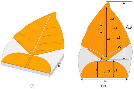
Figure 1.
The structure of the bionic leaf-shaped flexible wideband antenna (a) 3D model of a leaf-shaped antenna created in HFSS. (b) 2D layout dimensions of a leaf-shaped antenna.

Table 1.
The environmental adaptability of the PI film.
2.2. The Design Principle of the Leaf-Shaped Antenna
Traditional monopole antennas have a narrow operating frequency range, with a typical relative bandwidth of less than 5%. The core of the leaf-shaped monopole antenna design lies in utilizing the fractal characteristics of the leaf shape to create a multipath current distribution, introducing multiple resonance points, thereby achieving wideband performance. When simulating the leaf-shaped antennas, we need to follow the basic principles of electromagnetic radiation [21,22,23,24]. The electrical length Lp of the radiation element is determined by the wavelength λL corresponding to the lowest frequency at which the antenna operates, as shown in Formula (1).
The total length of the feed line and the radiation part is approximately one-third of the wavelength λL.
The length of the transition line connecting the feeding line to the radiation part is between 0.01 and 0.02 times the wavelength λL.
3. Results and Discussion
This part provides a detailed description of the characteristics of the antenna structure, the main design steps, and the evolution process. It presents the electric field distribution of the antenna at different frequency points, as well as the simulation results and measurement results, followed by an analysis. At the end of this part, a comparison is given between the antenna presented in this paper and similar biomimetic antennas from prior works.
3.1. The Design Steps of the Antenna
The evolution process of the design of the flexible leaf-shaped antenna can be divided into three main steps, as shown in Figure 2. Step 1 is the initial structure, where the feeding structure uses a symmetrical coplanar waveguide, and the overall height of the radiation element is similar to that of a leaf. As shown in the simulation curve in Figure 3b, the S11 performance of the initial structure is poor and does not meet the wideband requirements.
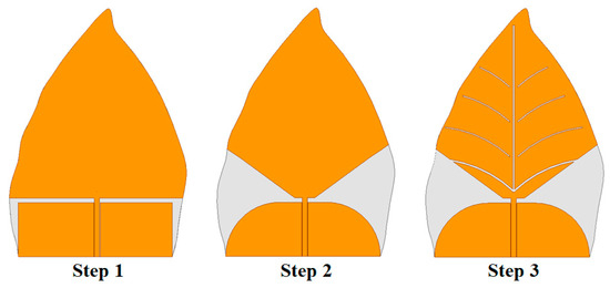
Figure 2.
The main evolution steps of the leaf-shaped antenna design.
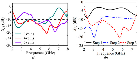
Figure 3.
(a) Comparison curve of antennas with different numbers of veins. (b) The simulation results of the antenna’s S11 corresponding to the evolution steps.
In Step 2, the rectangular ground plane of the initial structure is replaced with a semi-elliptical ground plane, and two symmetrical triangular sections are cut out of the radiation patch. In the structure where the CPW-type feed line transitions to the radiating arm, the electric field undergoes a rotation process from a transverse field distribution to a vertical field distribution. In the transition structure with a rectangular ground plane, the field rotation is too sharp. After the introduction of an elliptical ground plane, the electric field rotation becomes smoother and more gradual, which is beneficial for impedance matching. This shape change improves the electromagnetic distribution of the transition between the feed structure and the radiating circuit, optimizing the impedance matching. As shown in the S11 curve in Figure 3b, the return loss characteristics have been significantly improved.
In Step 3, a main vein slot and four symmetrical branch vein slots are etched on the radiating patch. The vein slots introduce multiple inter-slot capacitances. The vein slots not only provide conductive paths of different electrical lengths, naturally supporting multi-frequency resonance, but also improve the matching performance in the high frequency band. The effect of different numbers of vein slots on the bandwidth widening varies, as shown in Figure 3a. We ultimately chose the structure with four vein slots. The above structural optimization increases the antenna’s impedance bandwidth from 2.4 GHz to 7.1 GHz, achieving a relative bandwidth of about 100%, resulting in wideband performance.
The key physical dimension parameters of the leaf-shaped antenna are listed in Table 2. To further verify the wideband characteristics of the antenna, Figure 4 shows the current distribution at four frequency points. By observing electric field distributions on the antenna surface at different frequency points, the role of the vein-like slots at different frequencies can be analyzed.
Table 2.
The key physical dimensions of the leaf-shaped antenna.
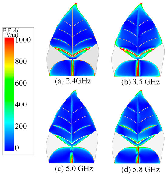
Figure 4.
Surface electric field distribution of the antenna at different frequencies.
3.2. The Simulation Result of the Antenna
Figure 4 shows the electric field distribution at some commonly used frequencies. As shown in Figure 4a, at low frequencies, the current is mainly concentrated in the lower half of the petiole region and the edge of the gap in the upper half of the leaf. As the frequency increases, the current spreads towards the upper half of the leaf, as shown in Figure 4b,c. At 5.8 GHz, the current density at the gap edge of the upper half leaf’s vein increases significantly, thereby exciting additional modes. In Figure 4d, it is also observed that there is a noticeable current distribution at the edge of the ground plane, indicating that the semi-elliptical ground structure has a significant impact on the antenna’s impedance matching.
3.3. The Measured Results of the Antenna
The comparison photo of the fabricated antenna and the leaves of the aquifoliaceae family in nature is shown in Figure 5a, where the biomimetic appearance effect is realistic. The green covering is a thin layer of color applied on the PI substrate to make the leaf-shaped antenna appear more realistic. A more detailed image of the fabricated prototype, including the connector soldering, is shown in Figure 5b. Figure 5c displays the test scenario for the bending performance of the leaf-shaped antenna. The antenna is fixed separately along the X-axis and Y-axis on a cylindrical foam, and S-parameters are measured using the Rohde & Schwartz vector network analyzer ZNA43. The test results are shown in Figure 6, where it can be observed that the change of S11 is small under different bending radii, indicating that the antenna has good stability. The measured impedance bandwidth is 2.4 GHz to 7.1 GHz (relative bandwidth is about 100%). In comparison with the simulation results, the impedance bandwidth is slightly narrower, mainly due to the irregular shape of the manually soldered joint solder points.
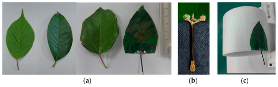
Figure 5.
(a) A photograph of leaves and the leaf-shaped antenna. (b) A detailed image of the fabricated prototype. (c) The test scenario for the bending performance of the leaf-shaped antenna.
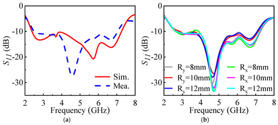
Figure 6.
(a) The comparison of S11 between the measured result and the simulation result. (b) The S11 variation under different bending radius Rx/Ry values.
The radiation performance of the leaf-shaped antenna was tested in a microwave anechoic chamber using the planar near-field scanning method, as shown in Figure 7. Due to the travel limitations of the scanning test rack, the test range of the antenna radiation pattern is ±60°. The normalized radiation pattern of the tested antenna is shown in Figure 8, and the measured results are generally consistent with the simulation results. Figure 9 shows the test curve of the antenna realized gain, where it can be seen that the measured results closely match the simulated results, with a maximum gain of 5.4 dBi around 5.0 GHz.
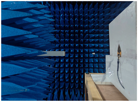
Figure 7.
The scene of the near-field testing of the leaf-shaped antenna in the microwave anechoic chamber.
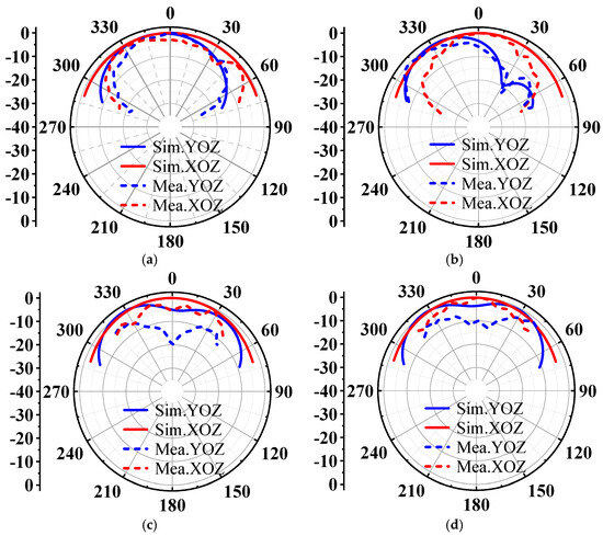
Figure 8.
The comparison of the radiation pattern of the antenna between simulation data and the measured results: (a) 2.4 GHz; (b) 3.5 GHz; (c) 5.0 GHz; (d) 5.8 GHz. The XOZ plane corresponds to phi = 90°, theta = 0°. The YOZ plane corresponds to phi = 0°, theta = 0°.
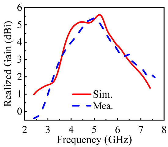
Figure 9.
The comparison of the realized gain of the antenna between the simulation data and the measured results.
Compared to the prior biomimetic wideband antennas, the leaf-shaped antenna proposed in this paper not only has an ultra-low profile and a wide operating bandwidth, but also features a highly realistic leaf shape, making it ideal for camouflage scenarios. Table 3 compares some key parameters of the antenna proposed in this paper with those of similar prior antennas.
Table 3.
The comparisons of key parameters between the antenna proposed in this paper and similar prior antennas.
Compared with the simulation results, the gain difference is small, while the difference in the radiation pattern is noticeable. The main reasons are as follows: (1) The electromagnetic parameters (such as dielectric constant, loss tangent) of the PI flexible substrate set in the simulation software differ somewhat from the actual dielectric constant, which introduces more errors in the radiation pattern test. (2) Due to some unpredictable errors in the alignment of the radiation centers of the horn probe in the testing system and the radiation center of the leaf-shaped antenna, the actual far-field radiation pattern is not as symmetrical and perfect as the simulation. Therefore, it is hard for the XOZ and YOZ plane cuts in the measurement to perfectly overlap with those in the simulation. (3) Manual soldering and testing alignment also introduce some unpredictable errors.
4. Conclusions
This paper proposes a leaf-shaped flexible antenna. To achieve wideband performance, the rectangular ground plane is replaced by a semi-elliptical ground plane to improve the matching impedance of the feed line. The radiating patch is etched with a symmetrical leaf-vein-type slot structure, introducing coupling capacitance to improve resonant behavior at high frequencies. The test results show that the antenna not only exhibits good radiation characteristics over a wide frequency range but also demonstrates good flexibility and stability and a realistic aquifoliaceae leaf-like appearance. The operating bandwidth of the leaf-shaped antenna is from 2.4 GHz to 7.1 GHz, with an average gain of 3 dBi, and the maximum gain is 5.4 dBi. The biomimetic leaf-shaped antenna can cover multiple communication frequency bands, including n41, n78, n79, and ISM 5.8 GHz, making it applicable in areas such as battlefield reconnaissance, wildlife monitoring, and key area surveillance.
Author Contributions
S.T. and Q.W. are responsible for the methodology. Q.W. is responsible for simulation. S.T. is responsible for writing. L.Z., Q.S. and B.T. are responsible for validation. All authors have read and agreed to the published version of the manuscript.
Funding
This research received no external funding.
Data Availability Statement
Data is contained within the article.
Conflicts of Interest
Author Qiyang Wang was employed by the company Najing Corad Electronic Equipment Co., Ltd. The remaining authors declare that the research was conducted in the absence of any commercial or financial relationships that could be construed as a potential conflict of interest.
References
- Yu, Z.; Wang, F.; Zhang, R.; Niu, R.; Chang, Y.; Ran, X.; Sun, R.; Zhang, G.; Lu, Z. A Flexible Multi-Band Antenna with a Spider Web-like Structure for 4G/5G/GPS/ WIMAX/WLAN Applications. Electronics 2025, 14, 253. [Google Scholar] [CrossRef]
- Zhang, H.; Lee, S. Robot Bionic Eye Motion Posture Control System. Electronics 2023, 12, 698. [Google Scholar] [CrossRef]
- Wang, R.; Sun, J.; Dai, J.S. Design analysis and type synthesis of a petal-inspired space deployable-foldable mechanism. Mech. Mach. Theory 2019, 141, 151–170. [Google Scholar] [CrossRef]
- Niu, H.; Li, H.; Gao, S.; Li, Y.; Wei, X.; Chen, Y.; Yue, W.; Zhou, W.; Shen, G. Perception-to-cognition tactile sensing based on artificial-intelligence-motivated human full-skin bionic electronic skin. Adv. Mater. 2022, 34, 2202622. [Google Scholar] [CrossRef]
- Li, H.; Xiao, S.; He, L.; Cai, Q.; Liu, G. A Dual-Band 8-Antenna Array Design for 5G/WiFi 5 Metal-Frame Smartphone Applications. Micromachines 2024, 15, 584. [Google Scholar] [CrossRef] [PubMed]
- Zulkifli, F.Y.; Wahdiyat, A.I.; Zufar, A.; Nurhayati, N.; Setijadi, E. Super-Wideband Monopole Printed Antenna with Half-Elliptical-Shaped Patch. Telecom 2024, 5, 760–773. [Google Scholar] [CrossRef]
- Huang, G.-L.; Chang, T.-Y.; Sim, C.-Y.-D. Wideband Eight-Antenna Array Designs for 5G Smartphone Applications. Electronics 2024, 13, 2995. [Google Scholar] [CrossRef]
- Wang, Z.; You, W.; Yang, M.; Nie, W.; Mu, W. Design of MIMO Antenna with Double L-Shaped Structure for 5G NR. Symmetry 2023, 15, 579. [Google Scholar] [CrossRef]
- Colella, R.; Chietera, F.P.; Michel, A.; Muntoni, G.; Casula, G.; Montisci, G.; Catarinucci, L. Electromagnetic characterisation of conductive 3D-Printable filaments for designing fully 3D-Printed antennas. IET Microw. Antennas Propag. 2022, 16, 687–698. [Google Scholar] [CrossRef]
- Tian, S.; Zhang, J.; Shu, X.; Chen, L.; Niu, X.; Wang, Y. A novel evaluation strategy to artificial neural network model based on bionics. J. Bionic Eng. 2022, 19, 224–239. [Google Scholar] [CrossRef]
- Yu, H.; Zhang, J.; Zhang, S.; Han, Z. Bionic structures and materials inspired by plant leaves: A comprehensive review for innovative problem-solving. Prog. Mater. Sci. 2023, 139, 101181. [Google Scholar] [CrossRef]
- Musa, U.; Shah, S.M.; Majid, H.A.; Mahadi, I.A.; Rahim, M.K.A.; Yahya, M.S.; Abidin, Z.Z. Design and Implementation of Active Antennas for IoT-Based Healthcare Monitoring System. IEEE Access 2024, 12, 48453–48471. [Google Scholar] [CrossRef]
- Yassin, M.E.; Hussein, K.F.A.; Abbasi, Q.H.; Imran, M.A.; Mohassieb, S.A. Flexible Antenna with Circular/Linear Polarization for Wideband Biomedical Wireless Communication. Sensors 2023, 23, 5608. [Google Scholar] [CrossRef] [PubMed]
- Masoumi, A.R.; Yusuf, Y.; Behdad, N. Biomimetic antenna arrays based on the directional hearing mechanism of the parasitoid fly Ormia Ochracea. IEEE Trans. Antennas Propag. 2013, 61, 2500–2510. [Google Scholar] [CrossRef]
- You, B.; Ou, Y.; You, J.; Xu, H. A Double-Veined Leaf-Shaped Bionic Meta-Element and Array Loading Antennas for Radiation Beam Control. IEEE Access 2021, 9, 69814–69829. [Google Scholar] [CrossRef]
- Jiang, W.; Liu, Y.; Gong, S.; Hong, T. Application of bionics in antenna radar cross section reduction. IEEE Antennas Wirel. Propag. Lett. 2009, 8, 1275–1278. [Google Scholar] [CrossRef]
- Yu, Z.; Chang, Y.; Niu, R.; Zhang, R.; Wang, F.; Sun, R.; Zhang, G.; Ran, X. A New Koch and Hexagonal Fractal Combined Circular Structure Antenna for 4G/5G/WLAN Applications. Electronics 2025, 14, 237. [Google Scholar] [CrossRef]
- Biswas, B.; Ghatak, R.; Poddar, D.R. A fern fractal leaf inspired wideband antipodal Vivaldi antenna for microwave imaging system. IEEE Trans. Antennas Propag. 2017, 65, 6126–6129. [Google Scholar] [CrossRef]
- Li, Y.; Yu, Z.; Xie, T.; Yu, J.; Wang, L.; Gao, X. A novel binary branch bionic antenna for communication and navigation. Int. J. RF Microw. Comput. Aided Eng. 2022, 32, e23037. [Google Scholar] [CrossRef]
- Rmili, H.; Oueslati, D.; Ben Trad, I.; Floch, J.M.; Dobaie, A.; Mittra, R. Investigation of a random-fractal antenna based on a natural tree-leaf geometry. Int. J. Antennas Propag. 2017, 2017, 2202622. [Google Scholar] [CrossRef]
- Ran, X.; Yu, Z.; Xie, T.; Li, Y.; Wang, X.; Huang, P. A novel dual-band binary branch fractal bionic antenna for mobile terminals. Int. J. Antennas Propag. 2020, 2020, 19. [Google Scholar] [CrossRef]
- Iriqat, S.; Yenikaya, S.; Secmen, M. Dual-Band 2 × 1 Monopole Antenna Array and Its MIMO Configuration for WiMAX, Sub-6 GHz, and Sub-7 GHz Applications. Electronics 2024, 13, 1502. [Google Scholar] [CrossRef]
- Kundu, S. Experimental study of a printed ultra-wideband modified circular monopole antenna. Microw. Opt. Technol. Lett. 2019, 61, 1388–1393. [Google Scholar] [CrossRef]
- Zhang, B.; Chen, Z.N.; Zhou, Y.; Lou, Q.; Wang, J.; Mouthaan, K. Improving radiation pattern roundness of henge-like metaring-loaded monopoles above a finite ground for MIMO systems. Electromagn. Sci. 2024, 2, 1–12. [Google Scholar] [CrossRef]
Disclaimer/Publisher’s Note: The statements, opinions and data contained in all publications are solely those of the individual author(s) and contributor(s) and not of MDPI and/or the editor(s). MDPI and/or the editor(s) disclaim responsibility for any injury to people or property resulting from any ideas, methods, instructions or products referred to in the content. |
© 2025 by the authors. Licensee MDPI, Basel, Switzerland. This article is an open access article distributed under the terms and conditions of the Creative Commons Attribution (CC BY) license (https://creativecommons.org/licenses/by/4.0/).