Article

Enhanced Computer Numeric Controller Milling Efficiency via Air-Cutting Minimization Using Logic-Based Benders Decomposition Method

by
Hariyanto Gunawan
1,2,*,
Didik Sugiono
3,
Ren-Qi Tu
1,2,
Wen-Ren Jong
1,2 and
AM Mufarrih
1
1
Department of Mechanical Engineering, Chung Yuan Christian University, Taoyuan 320314, Taiwan
2
R&D Center for Smart Manufacturing, Chung Yuan Christian University, Taoyuan 320314, Taiwan
3
Department of Mechanical Engineering, Qomaruddin University, Gresik 61152, Indonesia
*
Author to whom correspondence should be addressed.
Electronics 2025, 14(13), 2613; https://doi.org/10.3390/electronics14132613 (registering DOI)
Submission received: 1 April 2025 / Revised: 13 June 2025 / Accepted: 25 June 2025 / Published: 28 June 2025
(This article belongs to the Special Issue Advances in Industry 4.0 Technologies)

Abstract

In computer numeric controller (CNC) milling machining, air-cutting, where the tool moves without engaging the material, will reduce the machining efficiency. This study proposes a novel methodology to detect and minimize non-productive (air-cutting) time in real-time using spindle load monitoring, vibration signal analysis, and NC code tracking. A logic-based benders decomposition (LBBD) approach was used to optimize toolpath segments by analyzing air-cutting occurrences and dynamically modifying the NC code. Two optimization strategies were proposed: increasing the feedrate during short air-cutting segments and decomposing longer segments using G00 and G01 codes with positioning error compensation. A human–machine interface (HMI) developed in C# enables real-time monitoring, detection, and minimization of air-cutting. Experimental results demonstrate up to 73% reduction of air-cutting time and up to 42% savings in total machining time, validated across multiple scenarios with varying cutting parameters. The proposed methodology offers a practical and effective solution to enhance CNC milling productivity.

1. Introduction

In the context of Industry 4.0, improving machining efficiency is essential to meet the growing demand for high-quality and low-cost production. In the CNC machining process, the time when the tool is removing material is called productive cutting time. However, there is a condition when the tool is moving without engaging the material, which is called non-productive (or called air-cutting) time. In particular, one critical source of inefficiency is non-productive (air-cutting) tool movement that increases cycle time and energy use. Although many studies have explored toolpath optimization using genetic algorithms and heuristics, these are typically offline strategies with limited adaptability to real-time variations. Furthermore, toolpaths generated by computer-aided manufacturing (CAM) software depend heavily on operator expertise, often resulting in suboptimal machining time. Some previous studies approached different methods to reduce machining times. Daneshmand et al. [1] used commercial software CATIA V5R18 and MASTER CAM V9 to simulate toolpath planning strategies. The results indicated that endmill tools with the back-and-forth toolpath strategy used in CATIA produced minimum machining time. Corso et al. [2] used a deterministic scheme, the genetic algorithm (GA), and simulated annealing (SA) to minimize the machining time. The results showed that the GA method generated shorter machining times than the other two methods. Xu et al. [3] proposed an annealing algorithm for NC machining optimization to obtain the shortest toolpath. Zhang et al. [4] developed a mathematical model to optimize the cutting sequence in NC machining to obtain the shortest toolpath. However, this method is limited to the machining of independent features and, therefore, the efficiency of the overall machining improvement is limited.
Nishida et al. [5] proposed a method to automatically generate toolpaths based on a 3D CAD model to modify toolpaths to eliminate non-productive (air-cutting) motion to reduce the machining time. Oysu et al. [6] combined pre-processing and post-processing to improve GA performance and optimize the toolpath by reducing air-cutting while machining. Different toolpath optimization techniques have been proposed to minimize air-cutting [7,8,9,10]. However, these methods often fail to comprehensively reduce air-cutting in real-time machining scenarios.
Monitoring the machining process is required to investigate the productive cutting time and non-productive (air-cutting) time in the machining process. To complement optimization strategies, researchers have also focused on monitoring techniques to identify and analyze machining state in real-time. Liang et al. [11] utilized electric power data during dynamic machining processes to identify the abnormality. Emec et al. [12] proposed a method that used electrical power for online fault monitoring in machine tools. The advantage of this technique was that the measurement did not interrupt or delay the machining processes. Chen et al. [13] considered electrical energy to investigate the machining efficiency. Song [14] measured the vibration signal and the corresponding time series model to monitor the cutting process. It can predict the processing status through theoretical analysis and experimental methods.
Artificial intelligence (AI) technology has also been used for process monitoring and optimization. Wu et al. [15] used a transfer-learning-enhanced ResNet50 deep learning model for real-time monitoring of surface roughness. The cutting force signals were converted to a time–frequency diagram via continuous wavelet transform for feature extraction. Jones et al. [16] used multi-sensor data fusion combined with machine learning for predicting tool wear in CNC machining. Gohari et al. [17] explored the advancement in cyber-physical systems (CPS) for optimizing high-performance machining processes, especially for difficult-to-cut materials, within the context of Industry 5.0. It concluded that the integration of various comprehensive optimization approaches can handle complexities and disturbances in real-time. Additionally, an ideal CPS for high-performance machining that combines offline simulation and optimization with online monitoring and control, leveraging AI-based reduced-order modeling for efficient real-time predictions. Yu et al. [18] proposed an edge intelligence-driven digital twin (DT) architecture for CNC systems to address the limitation of computing power and network resources when integrating AI into traditional CNC machining. The system enables quick and reliable real-time tool status acquisition, facilitating predictive maintenance and contributing to improved machining quality and reduced production costs.
Recent research has explored decomposition methodologies to enhance machining efficiency. Decomposition techniques break down machining operations into smaller segments, enabling better control over air-cutting time and feedrate adjustments. Massoni et al. [19] utilized decomposition methods for complex part manufacturing, reducing material waste and energy consumption. He et al. [20] optimized machining energy savings using decomposition-based strategies.
Although air-cutting minimization has been investigated in prior research, these studies have typically used offline toolpath optimization with heuristics or simulation-based techniques. These approaches generally lack the adaptability to dynamic machining conditions and are difficult to implement directly in operational CNC environments. Additionally, few investigations have pursued the integration of monitoring systems with live NC code adjustment to reduce air-cutting in real-time. We found several research gaps: (1) Real-time detection limitation. Previous methods often rely on pre-calculated simulations or static toolpath analyses. This study leverages real-time spindle load and vibration monitoring to identify air-cutting events during active machining operations. (2) Lack of closed-loop NC code feedback. While traditional approaches optimize machining paths offline, our system incorporates logic-based benders decomposition (LBBD) to dynamically update and refine NC code during execution, creating a closed feedback loop between monitoring and optimization. (3) Insufficient operator interaction tools. Many earlier solutions exist as standalone algorithms with minimal user interaction. In contrast, this work includes a user-friendly human–machine interface (HMI) developed in C# to provide clear visualization, real-time parameter tracking, and control over the optimization process. (4) Limited integration for real-world applications. Unlike most algorithm-focused research, this system is fully integrated with a commercial CNC controller via TCP/IP, ensuring practical deployment without interfering with existing legacy setups.
By tackling these challenges, this study applies the logic-based benders decomposition (LBBD) method to minimize air-cutting time during CNC machining. The proposed system offers a real-time, adaptive optimization framework that reduces air-cutting time but also enhances operational reliability, making it highly suitable for advanced manufacturing and Industry 4.0 environments.
The following sections explain how these concepts are applied in a practical system that integrates real-time signal analysis with adaptive toolpath modification. Section 2 presents the methodology, including the concept of LBBD, signal characteristics, air-cutting detection logic, and optimization using LBBD. Section 3 describes the experimental setup, including parameters and cutting conditions. Section 4 presents the design and functionality of the HMI system. Section 5 discusses the experimental results. Finally, Section 6 concludes with key findings and future directions.

2. Methodology

2.1. Concept of Logic-Based Benders Decomposition

To enable dynamic adjustment of tool movement and feedrates in response to real-time machining data, this study adopts logic-based benders decomposition (LBBD), a proven technique for solving complex, hybrid optimization problems, by breaking them into smaller, more manageable subproblems. It is particularly effective when a problem has both combinatorial (logical/discrete) and numerical (continuous) components. LBBD extends the classical Benders Decomposition by replacing the traditional Linear Programming-based (LP-based) subproblem with a logic-based (often constraint programming or heuristic) subproblem [21]. It alternates between a master problem, which handles the high-level (discrete or logic-based) decisions. A subproblem, which solves the lower-level (continuous, scheduling, or path-based) decisions based on the master problem’s output.
In CNC machining, problems often involve discrete toolpath selection or motion logic (e.g., when to switch from G01 to G00), combined with continuous variables like feedrate, spindle load, etc. LBBD is suitable to address these problems because it separates the decision logic, such as tool motion logic, air-cutting segmentation, from the numeric tuning (e.g., speed/feed optimization). In addition, it supports real-time, modular implementation, which makes it ideal for dynamic machining systems.
The master problem determines how to decompose an air-cutting segment into motions such as G00 and G01. The subproblem then evaluates whether the decomposition, accounting for feedrates and positioning errors, effectively minimizes machining time while ensuring safety. If the result is suboptimal, feedback is used to refine the next attempt. This iterative process continues between the master and subproblems until an efficient solution is achieved.

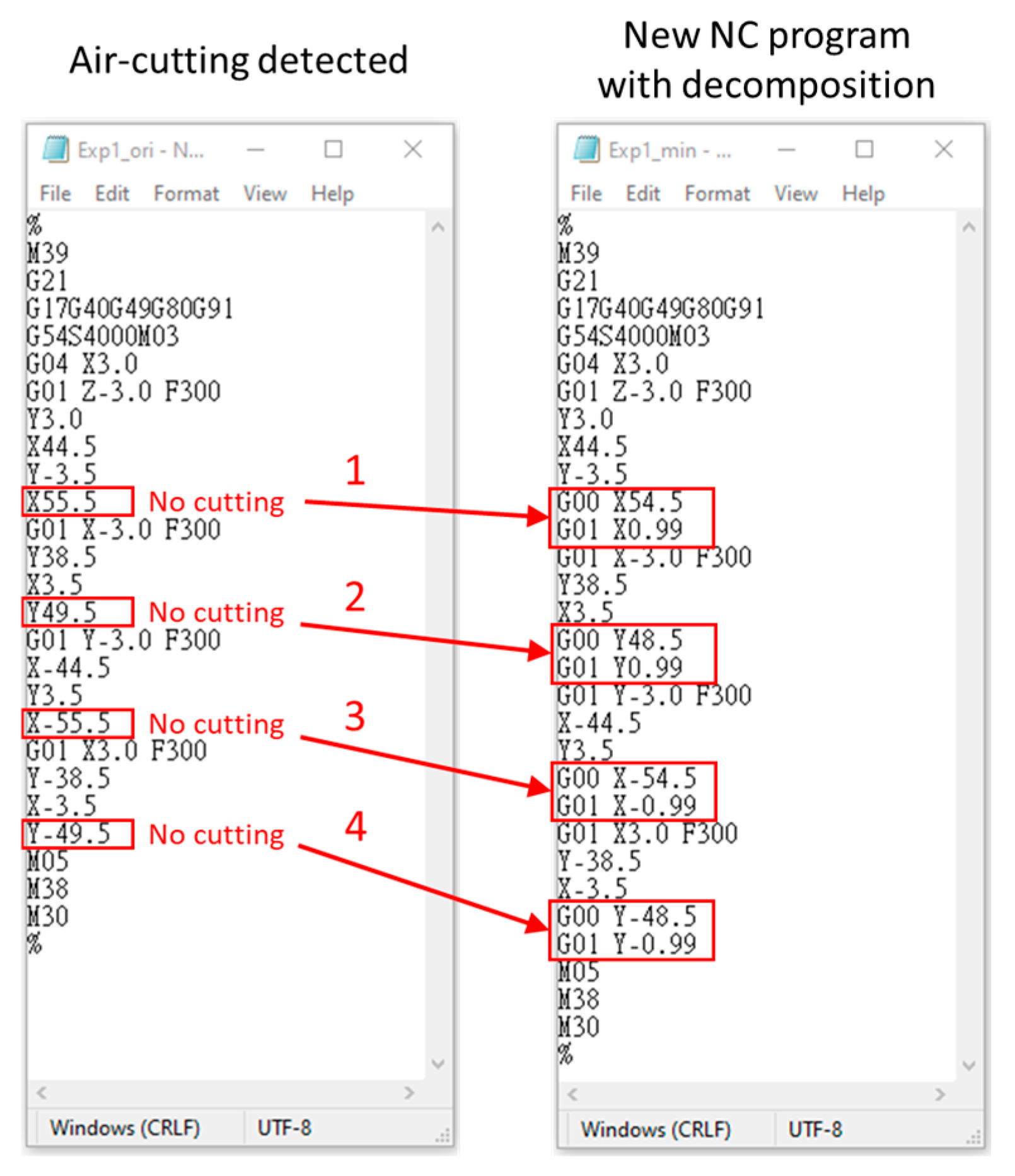
2.2. Air-Cutting Detection with Decomposition

To implement the LBBD-based optimization effectively, we must first detect air-cutting segments accurately during real-time machining. Our approach uses spindle load monitoring, cutting vibration analysis, and NC code tracking to distinguish between cutting and air-cutting states. The proposed method uses logic-based benders decomposition (LBBD). This technique breaks down the machining process into smaller segments to optimize tool movement and reduce air-cutting time. To capture real-time data such as spindle load and the currently executing NC program block, a previously developed communication module [22] connects to the CNC controller through a TCP/IP connection. In addition, vibration data are collected using accelerometers and a data acquisition (DAQ) system. Idle spindle load and vibration signals are also recorded to serve as baseline thresholds for distinguishing different machining states. By analyzing changes in spindle load and vibration, and linking them with their corresponding NC blocks, the system identifies whether the tool is cutting or air-cutting. Figure 1 shows the flowchart of the air-cutting detection system.
In the CNC machining process, the common G-code commands for cutting process are G01, G02, and G03, which represent a linear feed move, a clockwise arc feed move, and a counterclockwise arc feed move, respectively. Meanwhile, G00 is used for rapid motion and does not involve material removal. The time under G00 is classified as air-cutting time. To detect air-cutting segments across these commands, the regular expression and decomposition logic method was used to parse the NC code and isolate air-cutting zones. Figure 2 shows a typical spindle power profile. It clearly differentiates three states: idle, cutting, and air-cutting. Idle power refers to energy consumed when the machine is powered but not in motion. Cutting power refers to the energy consumed when the tool is removing material. Air-cutting power refers to the energy consumed when the tool is moving without engaging the material. It is important to note that spindle load varies between roughing and finishing due to different levels of material engagement. Additionally, high spindle speeds can result in high power consumption even during finishing operation with small depth of cut (DOC), width of cut (WOC), and feedrate. This probably leads to a misjudgment between cutting and air-cutting states.
To improve the accuracy of cutting state detection and avoid misjudgment based solely on spindle load, vibration signals were also analyzed in this study. Figure 3 shows typical vibration patterns during both cutting and non-cutting (air-cutting) states. It can be observed that the vibration during material removal is significantly different from that without material removal. However, because the original vibration signals fluctuate between positive and negative values, it is difficult to directly interpret the characteristics and trend of the vibration. Therefore, the root mean square (RMS) value of the vibration signal was calculated to better characterize the energy of the signal and clearly distinguish between productive cutting and non-productive (air-cutting) states.
The RMS vibration signal was synchronized with the execution of the NC code to determine the machining condition. Each G-code block has a defined execution period. For example, when G01 is initiated, the system records time T1, and when the control shifts to a new G-code block (G00, G02, or G03), time T2 is recorded, as shown in Figure 3. The machining time per block can be calculated using Equation (1).
T M , i = T i + 1 T i
where T i is the timestamp when execution of the i-th G-code block begins, T i + 1 is the timestamp when execution of the i-th G-code block ends, and T M , i is the machining time per block.
The total machining time is the cumulative of all G-code execution multiple intervals as follows:
T M _ t o t a l = i = 1 n T i + 1 T i
where n is the total number of G-code blocks.
When a G01 block is active, the system evaluates the vibration signal in real-time. If the RMS vibration value rises above the baseline (initial idle vibration level), the state is classified as cutting, and the current timestamp is recorded as L 1 , as shown in Figure 3. When the vibration signal drops back to baseline, the system identifies this transition as the end of cutting, and records the timestamp L 2 . Thus, for a given G01 block, the cutting time is calculated as follows:
T c u t , i = L 2 , i L 1 , i
where T c u t , i is the cutting time during the i-th G-code block, L 1 , i is the timestamp when cutting begins (RMS vibration exceeds baseline), and L 2 , i is the timestamp when cutting ends (RMS vibration returns to baseline). This formula assumes one continuous cutting segment within each motion block. If multiple cutting intervals occur within a single block, the formula can be generalized become the following:
T c u t _ t o t a l = j = 1 m i L 2 , i , j L 1 , i , j
where m i is the number of cutting intervals detected in block i, L 1 , i , j is the start of the j-th cutting interval in block i, and L 2 , i , j is the end of the j-th cutting interval in block i.
The air-cutting time is derived by subtracting the cutting time from the machining time. The air-cutting time per block with multiple cutting intervals can be calculated using Equation (5).
T a i r , i = T i + 1 T i j = 1 m i L 2 , i , j L 1 , i , j
where T a i r , i is the air-cutting time in block i.
The total air-cutting time for multiple intervals across all blocks can be calculated using Equation (6).
T a i r _ t o t a l = i = 1 n T i + 1 T i j = 1 m i L 2 , i , j L 1 , i , j
where the first term is the total machining time, and the second term is the total cutting time. This procedure is consistently applied to other motion commands such as G02 and G03 (circular interpolation). Since G00 represents rapid motion with no material engagement, the entire time under this command is automatically categorized as air-cutting time.
In CNC milling machining, the cutting time can be theoretically calculated using Equation (7). If the NC code is provided, the cutting time, air-cutting time, and total machining time can be analyzed using Equation (7).
T m i l l i n g m i n u t e s = L F   or   T m i l l i n g s e c o n d s = L × 60 F
where T m i l l i n g is the milling time (minutes), L is the cutting distance (mm), and F is the feedrate (mm/minute).

2.3. Air-Cutting Optimization with Decomposition

After identifying air-cutting events using spindle load and vibration signals, the next step is to reduce these non-productive segments through decomposition-based motion planning. This study implements two complementary strategies:
  • Feedrate acceleration under linear motion (G01) for short air-cutting distances.
  • Logic-based benders decomposition (LBBD) for longer paths, which segments the motion into rapid (G00) and linear (G01) segments while compensating for machine positioning errors.
The optimization process is illustrated in Figure 4. The pseudocode for air-cutting time optimization is given in Algorithm 1. To ensure safety, the algorithm incorporates machine positioning error from a reference database during rapid motion calculations. Table 1 shows the summary of optimization conditions.
The algorithm for optimizing air-cutting time is as follows:
  • Identify and analyze the air-cutting length (L).
  • If L ≤ 10 mm:
    Use G01
    Increase the feedrate by 50%
    New feedrate:
F n = F 0 + F 0 × 50 %
where F n is the new feedrate, and F 0 is the original federate.
3.
If L > 10 mm:
Apply he decomposition method.
X-axis decomposition:
L X G 00 = L X 1   m m
L X G 01 = L X LX G 00 Error
Y-axis decomposition:
L Y G 00 = L Y 1   m m
L Y G 01 = L Y LY G 00 Error
4.
Regenerate the NC code automatically based on optimized movements.
5.
Compare air-cutting and machining time before and after optimization. If the new air-cutting time and machining time are lower than the original, then save this new NC program and finish; otherwise, repeat the analysis to find a better solution.
Algorithm 1. Pseudocode for air-cutting time optimization
Input air-cutting segment with x, y coordinates and original feedrate F o
Measure air-cutting length (L)
If L ≤ 10 mm
  Apply G01
  Increase feedrate: F n = F o × 1.5
Else
  Apply decomposition:
    L X G 00 = L X 1
    L X G 01 = L X L X G 00 E r r o r
    L Y G 00 = L Y 1
    L Y G 01 = L Y L Y G 00 E r r o r
  Assign:
   G00 ⟶ ( L X G 00 ,   L Y G 00 )
   G01 ⟶ ( L X G 01 ,   L Y G 01 )
Generate updated NC code with modified commands
Simulate and compare new air-cutting and machining time
  If new time < original:
  Save optimized NC program
 Else: Reiterate decomposition or adjust parameters
End

3. Experiment

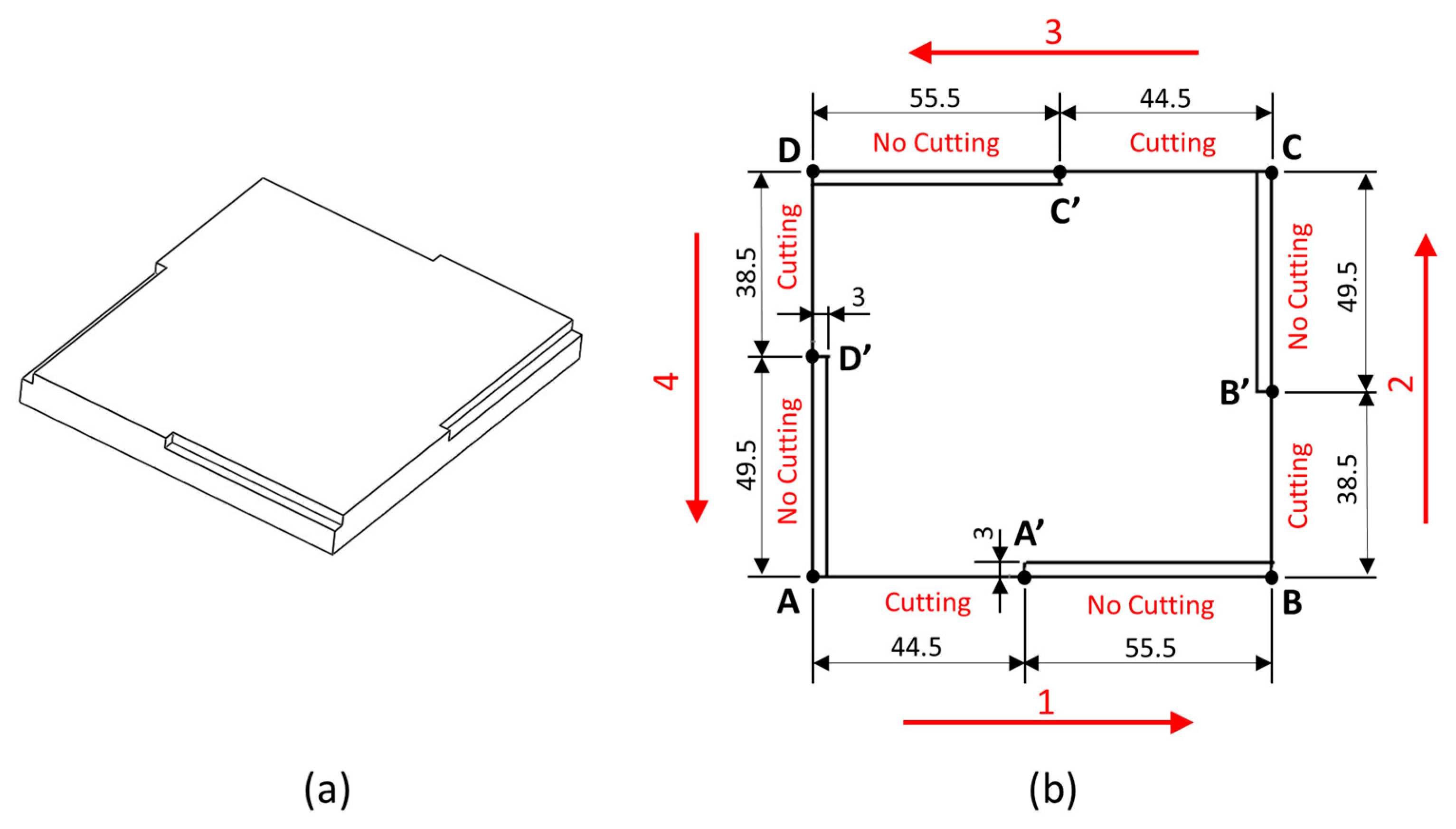
3.1. Experiment Design

The experimental framework was designed to characterize spindle load and vibration signals under both cutting and non-cutting conditions, with the goal of developing reliable threshold values for real-time air-cutting detection. Two diagnostic methods were implemented: (1) spindle load-based detection, and (2) vibration signal-based detection. These methods were selected because spindle load reflects macro-level cutting forces, while vibration signals, especially when measured with appropriate accelerometers, can sensitively capture micro-cutting conditions. Since cutting parameters influence signal clarity, both signals were analyzed in parallel to enhance detection accuracy.
Table 2 shows the cutting parameters for both experiments: the spindle load test and the vibration signal test. An aluminum workpiece material manufactured by Fapo Enterprise Co., Ltd., Taichung city, Taiwan with dimensions of length × width × thick = 100 × 80 × 70 mm was used in this experiment. A tungsten carbide endmill tool manufactured by Accu-Cut Industrial Co., Ltd., Taichung city, Taiwan with diameter of 10 mm and 3 flutes was used. To validate the detection performance of each signal type, the experiment was designed as follows:
  • Spindle load test:
    A straight-line cut along the Y-axis (120 mm path, 100 mm actual cut) was repeated 10 times using a feedrate of 1000 mm/min.
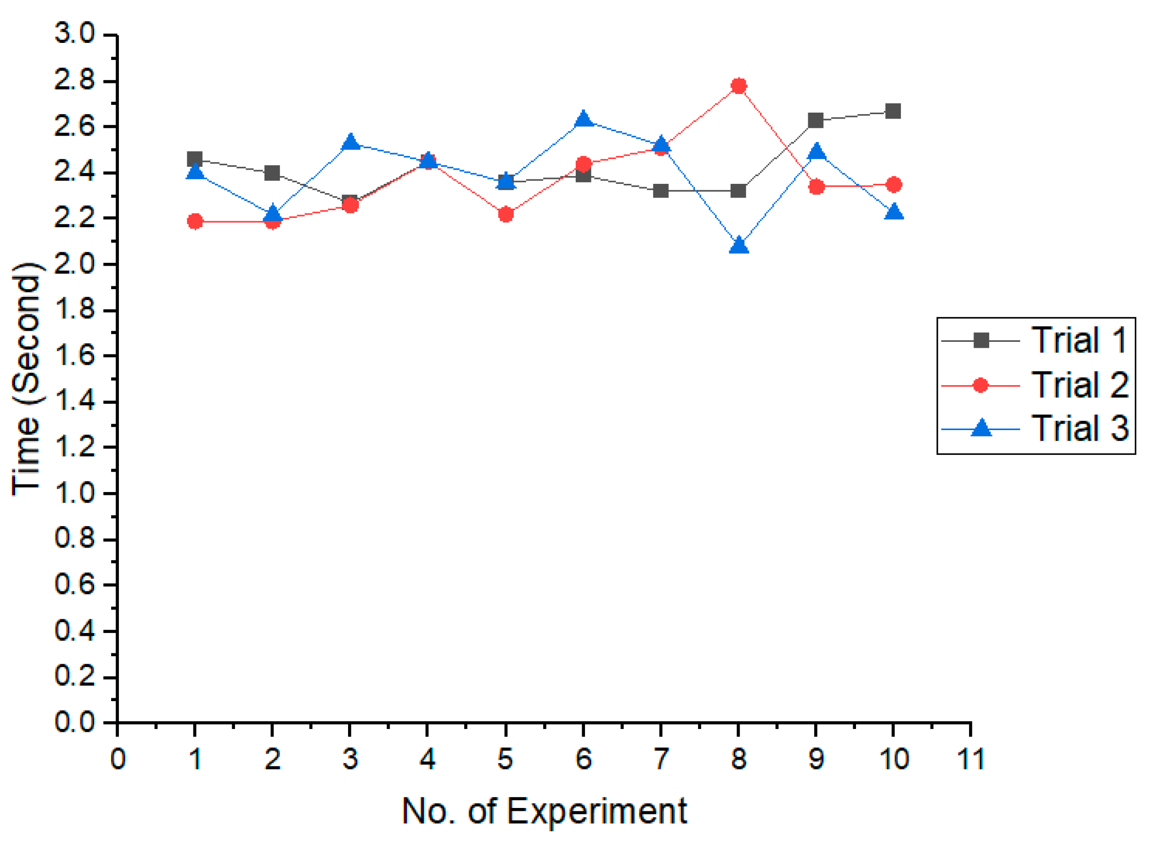
  • Vibration signal test:
    Micro-cutting was performed along the X-axis (200 mm path, 100 mm cut) with a feedrate of 600 mm/min and a shallow width of cut (0.1 mm), repeated 3 times.
To optimize the air-cutting time, the decomposition-based method is utilized. Portions of detected air-cutting paths are converted into rapid motion (G00) segments to reduce time. However, since G00 commands typically involve high feedrates (e.g., ≥5000 mm/min), they introduce risks of collision or overcutting if positioning errors are not considered. To ensure safe decomposition, the relationship between rapid motion and positioning error was analyzed. Table 3 shows the experiment design parameters for positioning error, and the step-by-step experiment is as follows:
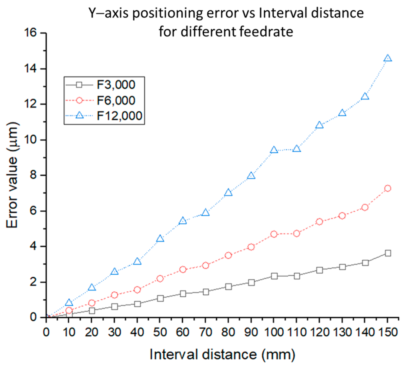
  • Positioning error was experimentally measured across the X and Y axes.
  • Feedrates of 3000, 6000, and 12,000 mm/min were tested.
  • Interval distances ranging from 10 to 200 mm (in 10 mm steps) were evaluated.
  • Each condition was repeated five times to ensure repeatability.
Table 3. Experiment design parameters for positioning error.
Feedrate (mm/min)Interval Distances (mm)Repetitions Per StepAxes Measured
300010–200 (step: 10 mm)5X, Y
600010–200 (step: 10 mm)5X, Y
12,00010–200 (step: 10 mm)5X, Y
The resulting error data were stored in a machine positioning error database, which feeds into the decomposition algorithm. These values are used to adjust G00 and G01 segment lengths to ensure safe motion boundaries during NC code regeneration. By combining diagnostic signal validation and machine-specific error compensation, this experiment setup ensures that the proposed decomposition-based air-cutting optimization algorithm is not only effective but also safe and practical for real machining environments.

3.2. Instruments

In the experiment, a 3-axis vertical CNC machining center YTM-763 manufactured by Yang Iron Precision Corp., Taichung city, Taiwan with X, Y, Z-axis stroke 760 × 400 × 350 mm, spindle maximum speed 12,000 rpm, equipped with a Delta NC-311A controller was used. The accelerometers produced by PCB piezotronics Inc., New York, NY, USA with model 353B15, the frequency range of 1–10 kHz, and sensitivity of 10 mV/g were mounted on the vise. Data acquisition (DAQ) produced by National Instrument Corp., Austin, TX, USA with the NI USB-4431 model, the maximum sampling rate of 102.4 kS/s was used to acquire and convert the vibration signals. The air-cutting and minimizing system was connected to the CNC controller via Ethernet cable, and then the NC machining and spindle load were captured and stored in the computer. To measure the machine positioning error, the HP5519A laser interferometer and the E1735A interface module with 10747F metrology software manufactured by Keysight Technologies Inc., Santa Rosa, CA, USA were used.

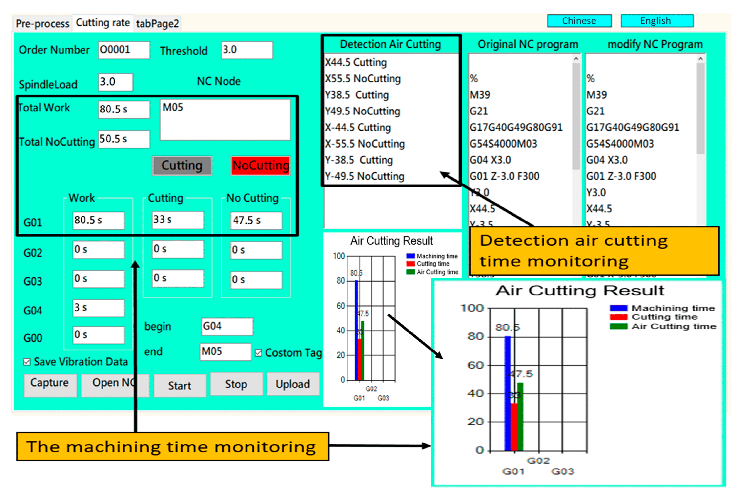
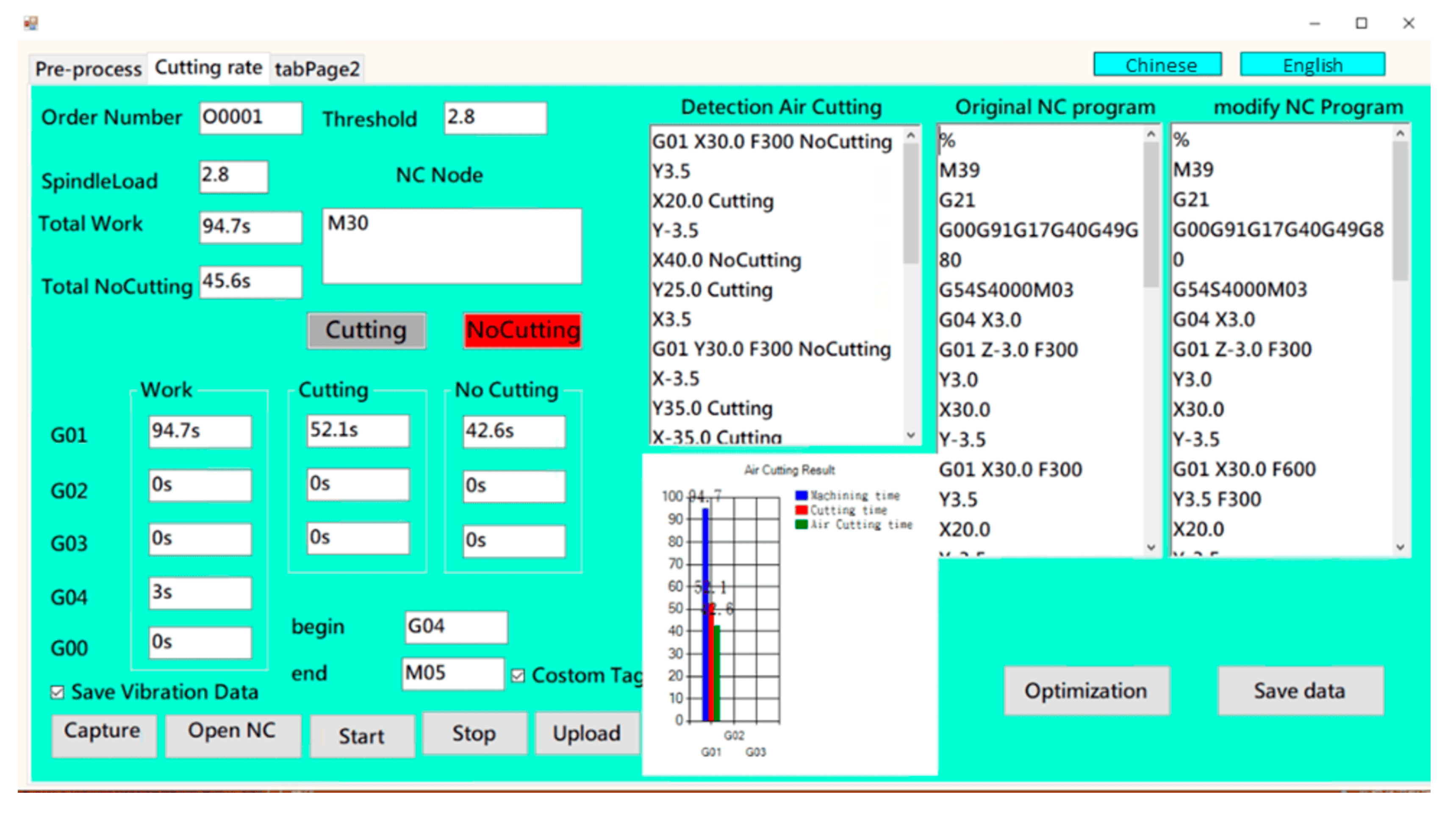
4. Human–Machine Interface

The air-cutting detection and minimizing system with a friendly human–machine interface (HMI) was designed and created using C# language. The system can real-time monitor the machining status of cutting or no-cutting, detect air-cutting and the air-cutting location, minimize the air-cutting time, calculate cutting time, air-cutting time, and machining time as shown in Figure 5. The numbered sections in Figure 5 represent the following functionalities:
Section 1: NC code tracker. Displays the currently executing NC code block in real-time.
Section 2: Machining state indicator. Indicates the current machining status (cutting or no-cutting), based on spindle load and vibration signal threshold.
Section 3: Air-cutting detection log. Displays the sequence and location of detected air-cutting segments.
Section 4: Time summary panel. Displays the measured total machining time, cutting time, and air-cutting time for each G-code type (G00, G01, G02, G03, G04).
Section 5: Bar chart visualization. Graphically presents machining time breakdown (blue for total machining time, green for air-cutting, and red for cutting time).
Section 6: Original NC program area. Displays the imported NC code.
Section 7: Modified NC program output. Displays the optimized NC code generated by the system after air-cutting minimization.
The user needs to input the spindle load threshold, vibration threshold, and import NC machining program. The imported NC program is displayed in the original NC program area (No. 6 in Figure 5). Subsequently, the system will capture the real-time spindle load and vibration signals. The current executing NC block is displayed in the NC code area (No. 1 in Figure 5). Furthermore, the collected data and signal were analyzed and used following the algorithms to determine the cutting or no-cutting state. When the current executing NC block is G01 or G02 or G03, if the spindle load value and vibration signal value are greater than the threshold value, then the system will judge as cutting state. Simultaneously, the system will record the current time, and the machining status in the HMI (No. 2 in Figure 5) will display “Cutting” state in green color. On the other hand, when the current executing NC block is G01 or G02 or G03, if the spindle load value and vibration signal value decrease from the cutting value to the threshold value, which the spindle load value is equal to spindle threshold value and the vibration signal value is equal to the vibration threshold value, then the system will judge it as the no-cutting state. Simultaneously, the system will record the current time, and the machining status in the HMI (No. 2 in Figure 5) will display “No-Cutting” state in red color. When the executing NC block is M30 that represents the machining is completed, the system will display the air-cutting detection and its location in the detection air-cutting area (No. 3 in Figure 5), and calculate all the recorded cutting time, air-cutting time, and machining time (No. 4 in Figure 5), also display it in a bar chart (No. 5 in Figure 5). Furthermore, the system will analyze and minimize the detected air-cutting time, regenerate the NC program, and display this new NC code in the Modify NC program area (No. 7 in Figure 5). Finally, the user can save the modified NC program with minimum air-cutting time.
Figure 5. Air-cutting detection and air-cutting time minimizing the human–machine interface.
Electronics 14 02613 g005

5. Results and Discussion

5.1. Air-Cutting Based on Spindle Load

Figure 6 and Figure 7 show the results of the air-cutting monitoring based on spindle load judgment. The cutting conditions and parameters followed the experiment design in Section 3.1. It can be seen in Figure 6 that the air-cutting time under the G00 command was consistent and reproducible. Similarly, when applying G01, the air-cutting time also exhibited stable and repeatable trends, as depicted in Figure 7. In addition, the deviation range of the measurement result is within one second, primarily due to the slight delay in real-time detection. Despite this minor lag, the overall monitoring performance remained highly stable.
To assess measurement reliability, the mean, standard deviation, and uncertainty were computed. For G00 air-cutting time, the mean was 2.39 s, with a standard deviation of 0.15 s and a relative uncertainty of 1.21%. In case of G01 air-cutting, the corresponding values for mean, standard deviation, and uncertainty were 3.46 s, 0.23 s, and 1.24%, respectively. For G01 cutting and machining time, the mean, standard deviation, and uncertainty results were 5.96 s, 0.16 s, 0.49% and 9.43 s, 0.17 s, 0.33%, respectively. Using Equation (7), the theoretical cutting time for a 100 mm distance at a feedrate of 1,000 mm/min is 6 s, which aligns closely with the cutting time detected by the system, confirming the accuracy of the monitoring method.

5.2. Air-Cutting Based on Vibration

The experiment parameters used for the air-cutting monitoring experiment based on cutting vibration signals are listed in Table 2. The accelerometer was mounted on the vise, and the cutting path followed the setup described in Section 3.1. The results of the experiment are presented in Table 4, showing consistent outcomes across three trials. The calculated mean, standard deviation, and measurement uncertainty for cutting time, air-cutting time, and total machining time were 10.4 s, 0.05 s, 0.44%; 11.9 s, 0.05 s, 0.39%; 22.4 s, 0.02 s, 0.07%, respectively. The average cutting time is approximately 10.4 s, while the total machining time averaged 22.4 s. Theoretically, with a feedrate of 600 mm/min over 100 mm cutting length, the expected cutting time is 10 s. The observed deviation of around 0.4 s is probably due to signal processing and judgment delays, but remains within an acceptable margin of error.

5.3. Positioning Error

The linear position error along the X-axis and Y-axis is shown in Figure 8 and Figure 9, respectively. It is seen in Figure 8 that the error value increases with the increase in interval distance. In addition, the higher feedrate, the larger the error value; for example, the error values for an interval distance of 50 mm are 0.534, 1.068, and 2.137 for a feedrate of 3000, 6000, and 12,000, respectively. This phenomenon agrees with the law of inertia, which states that a moving object will keep moving, so when the machine table is moving at a certain speed, it is difficult to stop immediately with zero error. A similar trend is also shown in the Y-axis positioning error in Figure 9.

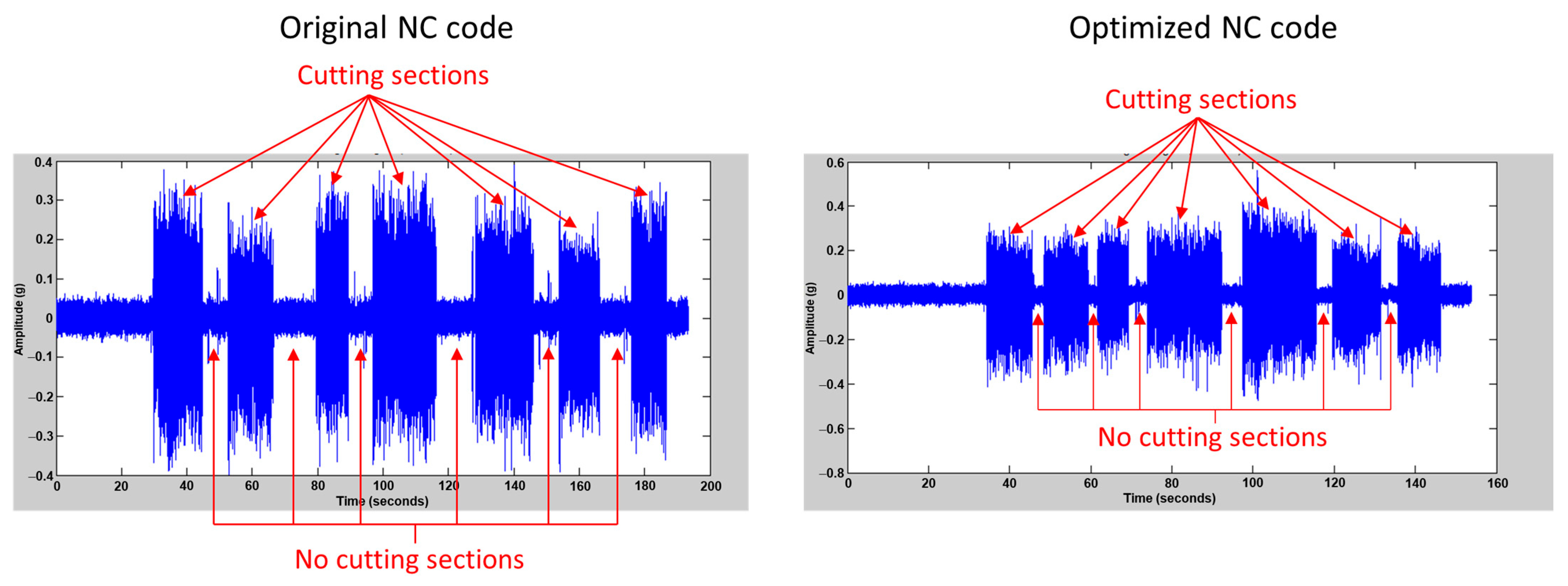
5.4. Verification Experiment

To verify the proposed system, the experiment was carried out on the basis of spindle load and vibration signal as a judgment. Since the air-cutting length is used to determine the minimizing air-cutting method, the experimental verification was divided into three scenarios to verify the efficiency of each method: (1) use the decomposition algorithm, (2) use the increased feedrate algorithm, and (3) use the combination of the increased feedrate and decomposition algorithms. The verification experiment used aluminum 6061 with hardness HB 30 [23] for the workpiece and an endmill cutting tool with a diameter of 10 mm, 3 flutes, and S220 carbide material. The cutting parameters are shown in Table 5.

5.4.1. Verification Experiment 1

In this experiment, the cutting process was in the X-axis and Y-axis direction with a workpiece length of 100 mm, a width of 78 mm, and a cutting path as shown in Figure 10. To show the capability to detect and minimize air-cutting, a workpiece with a groove on one side was prepared. The cutting toolpath follows the direction shown in Figure 10b. After air-cutting was detected, the decomposition method was applied to minimize the air-cutting. The first cutting tool started from point A to B, which consists of the cutting section A–A′ with a length of 44.5 mm and no-cutting section A′–B with a length of 55.5 mm. The second cutting tool moved from point B to C, which consists of the cutting section B–B′ with a length of 38.5 mm and no-cutting section B′–C with a length of 49.5 mm. The third cutting tool moved from point C to D, which consists of the cutting section C–C′ with a length of 44.5 mm and no-cutting section C′–D with a length of 55.5 mm. The fourth cutting tool moved from point D to A, which consists of the cutting section D–D′ with a length of 38.5 mm and no-cutting section D′–A with a length of 49.5 mm.
The cutting time and air-cutting time for each section can theoretically be calculated using Equation (7). For example, the distance A to A′ is 44.5 mm, the cutting time T 1 = 44.5 × 60 / 300 = 8.9   s and the distance A’ to B is 55.5 mm, the no-cutting time T 2 = 55.5 × 60 / 300 = 11.1   s . The same calculation method applies to each section, cutting time or no-cutting time, following the NC program until the end of the program. Based on the detailed calculation, the total cutting time, no-cutting time, and the total machining time were 33.2 s, 50.8 s, and 84 s, respectively. Figure 11 shows the air-cutting detected by the system. As seen, the cutting state with length of X44.5, Y38.5, X-44.5, Y-38.5, and the no-cutting state with a length of X55.5, Y49.5, X-55.5, Y-49.5 were detected and displayed in the detection air-cutting section. In addition, the cutting time, total no-cutting time, and the total machining time calculated by the system are 33 s, 50.5 s, and 80.5 s, respectively. Since G04 with the value of 3 s was used in the NC program, this value is counted as air-cutting, and the total machining time becomes 83.5 s. This result has good agreement with the theoretical calculation.
After the air-cutting was detected, the air-cutting length was analyzed according to the detected air-cutting data, and then air-cutting minimization was performed. Because the air-cutting lengths were 55.5, 49.5, 55.5, and 49.5 mm, which are larger than 10 mm, the decomposition method was used to minimize the air-cutting. Equations (9)–(12) were used to calculate the decomposition of the G01 and G00 values, then converted to the NC code. Furthermore, this NC code was integrated into the original NC program and generated a modified NC program as shown in Figure 12. To verify the efficiency of this modified NC program, it was performed and monitored by the system. The results showed that the cutting time, total air-cutting time, and total machining time were 33.5 s, 13.75 s, and 47.25 s, respectively. The total air-cutting is significantly reduced from 50.5 s to 13.75 s, or equal to 72.8%, after being minimized by using the decomposition method. This is because the original NC program used G01 with feedrate of 300 mm/mm, whereas the decomposition method added the G00 code with feedrate of 3000 mm/min. Additionally, the total machining time also decreases due to decreasing air-cutting time, so the total machining time savings is about 41.3%. The reduction in air-cutting time can also be seen in the vibration signal in Figure 13. Compared to the original NC code, no-cutting time section in the optimized NC code is shorter. Consequently, the total machining time is decreased and the machining efficiency is improved.
To assess measurement reliability, experiment 1 was repeated 5 times, then the mean, standard deviation, and uncertainty were computed. After optimization, the mean, standard deviation, and uncertainty were 14.39 s, 0.58 s, and 1.14% for air-cutting time. Meanwhile, the mean, standard deviation, and uncertainty for cutting time and total machining time were 33.78 s, 0.58 s, 1.71% and 48.17 s, 0.84 s, 1.76%, respectively.

5.4.2. Verification Experiment 2

In this experiment, the workpiece size and cutting path were the same as in experiment verification 1. The difference is that the air-cutting minimizing method used the increase feedrate method instead of the decomposition method. After the air-cutting was detected and the air-cutting length analyzed, air-cutting minimizing was performed with an increase in the original feedrate by 50%. Equation (8) was used to calculate new feedrate values. The feedrate used in this experiment was 300 mm/min, so the new feedrate is as follows:
  F n = 300 + 300 × 50 % = 450   mm / min
The new feedrate was then integrated into the original NC program and generated a modified NC program as shown in Figure 14. The verification result of the modified NC program showed that the cutting time, total air-cutting time, and total machining time were 32.5 s, 36.75 s, and 66.25 s, respectively. Since this experiment only increased feedrate to minimize air-cutting time, the air-cutting time reduction is about 27.2%. The total machining time saving is about 17.7%. It can be seen from the vibration signal comparison in Figure 15 that the reduction of no-cutting time is not as large as that using the decomposition method.
The mean, standard deviation, and uncertainty were calculated based on five repeated trials of experiment 2. The results indicate that the air-cutting time has a mean of 36.9 s, a standard deviation of 0.38 s, and an uncertainty of 1.05%. For cutting time, the mean, standard deviation, and uncertainty were 32.5 s, 0.48 s, and 1.49%, respectively. The total machining time has a mean of 66.41 s, with a standard deviation of 0.62 s and uncertainty of 0.94%.

5.4.3. Verification Experiment 3

In this experiment, the combination of the decomposition method and the increase feedrate method was used together to minimize the air-cutting time. A workpiece size 90.5 mm in length and 58.5 mm in width was used in this experiment. To demonstrate the capability of the system to detect and minimize air-cutting, a workpiece with a groove in the middle was prepared. The cutting path used for this experiment is shown in Figure 16. The cutting sections are A–B, C–D, E–F, and G–H; meanwhile, the no-cutting sections are B–C, D–E, F–G, and H–A.
Similarly to the previous experiment, the cutting time and the air-cutting time for each section can be theoretically calculated by using Equation (7). Each section of cutting time and no-cutting time according to the NC program was calculated. Based on the detailed calculation, the total cutting time, no-cutting time, and the total machining time were 32.6 s, 34.4 s, and 67 s, respectively. Figure 17 shows the air-cutting detected by the system. As seen, the cutting state with lengths of X35, X45.5, X-36, and X-46.5, and the no-cutting states with lengths of X10, X58.5, X-8.0, and X-58.5 were detected and displayed in the detection air-cutting section. Furthermore, the cutting time, the total no-cutting time, and the total machining time calculated by the system were 32.5 s, 33.5 s, and 63 s, respectively. G04 with the value of 3 s was used in the NC program, so the total machining time becomes 66 s. Compared to the theoretical calculation, the result from the system shows a close value with an error of about 1 s.
As seen in Figure 17, four instances of air-cutting were detected. Two instances of air-cutting have air-cutting lengths of 8 mm and 10 mm; therefore, Equation (8) was used to calculate the new feedrate. The other two have air-cutting lengths of 58.5 mm; therefore, Equations (9)–(12) were used to calculate the decomposed G01 and G00 values, then converted to NC code. Subsequently, this NC code was combined with the original NC program and generated a modified NC program as shown in Figure 18. This modified NC program was performed to verify the air-cutting reduction. The results showed that the cutting time, the total air-cutting time, and the total machining time were 32.5 s, 15 s, and 44.75 s, respectively. The total air-cutting is significantly decreased from 34.4 s to 15 s, or equal to 56.4% after being minimized by the combination of decomposition method and increasing feedrate method. In addition, the total machining time saving is about 28.9%. Figure 19 shows the vibration signal before and after minimizing. It is seen that the no-cutting time in Sections 1 and 3 only slightly decreases. This is because the air-cutting length is 8 mm and 10 mm, so the feedrate is increased by 50% to minimize the air-cutting time. On the contrary, the air-cutting length in no-cutting sections 2 and 4 is larger than 10 mm, so the NC code is decomposed into G01 and G00 to minimize the air-cutting time. Consequently, the air-cutting time in these sections decreases significantly after minimizing.
The mean, standard deviation, and uncertainty were computed from five repeated trials of experiment 3. The results show that the air-cutting time has a mean of 14.9 s, a standard deviation of 0.51 s, and an uncertainty of 3.36%. For cutting time, the mean, standard deviation, and uncertainty were 32.5 s, 0.46 s, and 1.41%, respectively. The total machining time has a mean of 44.52 s, with a standard deviation of 0.61 s and uncertainty of 1.35%.

5.4.4. Verification Experiment 4

In this experiment, a more complex geometry with various grooves, as shown in Figure 20, was prepared and used. The combination of the decomposition method and the increase feedrate method was used together to minimize the air-cutting time. A workpiece size 130 mm in length and 100 mm in width was used in this experiment. The cutting toolpath follows the direction shown in Figure 20b. The cutting sections are A–B, C–D, F–G, H–J, J–K, L–M, M–N, P–R, and S–A, while no-cutting sections are B–C, D–E, E–F, G–H, K–L, N–P, and R–S.
The cutting time and air-cutting time for each section can theoretically be calculated using Equation (7). The total cutting time, no-cutting time, and the total machining time were 51 s, 41 s, and 92 s, respectively. Figure 21 shows the air-cutting detected by the system. As seen, the cutting time, total no-cutting (air-cutting) time, and total machining time are 52.1 s, 45.6 s, and 94.7 s, respectively. Compared to the theoretical calculation, the result from the system shows a close value with an error of within 2 s. Figure 22 shows the original and optimized NC code. It can be seen that after the air-cutting was detected. The system will decompose into G00 and G01 code to reduce the air-cutting time. Figure 23 shows the vibration signal before and after minimizing. It is seen that the air-cutting time is decreased by the combination of the decomposition method and the increasing feedrate method.
To ensure the reliability and repeatability of the results, the statistical analysis was carried out. Experiment 4 with a complex shape was chosen to investigate the robustness of the system. Experiment 4 was repeated 5 times, and the results are tabulated in Table 6. The t-test is used to assess the significance of the reduction in air-cutting time across multiple trials. IBM SPSS Advanced Statistics Model 20 software was used for mean, standard deviation, t-test, and p-value analysis. Table 7 shows the t-test results comparing machining performance before and after optimization. As seen, the t-statistic is 130.12 with a very small p-value (<0.001), indicating a statistically significant reduction in total machining time after optimization. This confirms that the proposed method effectively reduces the overall machining time. The cutting time p-value is 0.362, showing no significant difference in cutting time before and after optimization. This is expected, as the cutting operations remained largely unchanged and the improvement focused on reducing non-cutting time. Furthermore, a very high t-statistic (55.44) and an extremely low p-value (<0.001) were found in the air-cutting time, indicating a statistically significant reduction in air-cutting time. This supports the claim that the optimization algorithm is highly effective in minimizing non-productive tool movements.

5.4.5. Verification Using SKD11 Material

To further assess the robustness of the method, an additional test was conducted using SKD11, a high-hardness workpiece material with Brinell hardness HB41 [24]. In this test, a 20 mm × 50 mm SKD workpiece was used with a linear toolpath designed to alternate between cutting and non-cutting movements. The tool followed this sequence: move to X40 (cutting), retract to Z5, move to X-40 (non-cutting return), move to Z-5.5, move to X40 (cutting), retract to Z5.5, move to X-40, and stop.
Figure 24 displays the vibration signals recorded during this test. As shown in Figure 24a, the system clearly distinguishes between cutting and air-cutting vibrations for SKD11. Similarly, distinct vibration patterns are observed for Al-6061, as shown in Figure 24b. Notably, the cutting vibration amplitude for SKD11 is higher than that for Al-6061, which is consistent with the greater material hardness of SKD11 (HB41) compared to Al-6061 (HB30). These results confirm that the system remains accurate and reliable when applied to harder materials, reinforcing its adaptability to diverse machining conditions.
From the verification experiments 1 to 4 results, the total machining time saving is in the range of 17~42%, or on average is around 30%, which is significant for practical application. In addition, the air-cutting time can be minimized up to 73% by using the decomposition method. Figure 25 shows the comparison of machining time before and after optimization for verification experiments 1 to 4.

6. Conclusions

This paper presents the development of a real-time air-cutting detection and minimizing system. By integrating spindle load data, vibration signals, and the NC program information into an algorithm, the system accurately identifies air-cutting events and their location during machining. It then applies optimization strategies to reduce non-productive time, thereby improving overall machining efficiency. A user-friendly human–machine interface was developed in C# to visualize and manage this process. Validation experiments demonstrated that the system could detect air-cutting occurrences with a time error margin of two seconds. Using the proposed decomposition method, air-cutting time was reduced by up to 73%, and total machining time decreased by as much as 42%.
Although the system was validated on a 3-axis CNC milling machine, the core algorithm, which is based on spindle load monitoring, vibration signals analysis, and G-code segmentation, is modular and adaptable to other machining processes. For example, in CNC turning, although the signal dynamics are different, similar thresholding techniques can be applied to detect non-cutting movement such as too retraction. In multi-axis milling, the decomposition logic can be extended to accommodate additional rotary axes (A, B, C), although this would require tool orientation mapping and more advanced collision avoidance strategies. Future work will focus on adapting the methodology for broader machine configuration and control systems.
This study did not account for the effects of tool wear or thermal variation, both of which can influence spindle and vibration signals. Future research will investigate the system’s performance across various tool wear stages, such as new tool, moderately worn, and heavily worn conditions, and incorporate temperature monitoring to enhance diagnostic accuracy. To further improve adaptability, we plan to implement adaptive thresholding and integrate machine learning (ML) techniques such as support vector machines (SVMs) and neural networks, enabling the system to learn from real-world data and adjust to evolving machining conditions.
Currently, positioning error is corrected using fixed subtraction for simplicity and efficiency in real-time execution. Further improvement will involve developing adaptive models based on machine-specific positioning deviation data under varying feedrates and distances, enabling more precise and dynamic error compensation. Moreover, the dimensional tolerances, virtual simulation to detect collision between tool-fixture interference, and surface quality will be investigated in the future.

Author Contributions

Conceptualization, idea, and theory development, H.G.; methodology, H.G. and D.S.; software, D.S. and R.-Q.T.; validation, D.S., R.-Q.T., and A.M.; formal analysis, H.G., D.S., R.-Q.T., and A.M.; investigation, H.G. and D.S.; resources, D.S. and H.G.; data curation, D.S.; writing—original draft preparation, H.G. and D.S.; writing—review and editing, H.G., W.-R.J.; visualization, D.S., W.-R.J., and A.M.; supervision, H.G. and W.-R.J. All authors have read and agreed to the published version of the manuscript.

Funding

This research was funded by the Ministry of Science and Technology (MOST) of Taiwan under the grant number 110-2622-8-033-002-SB.

Data Availability Statement

Data are contained within the article.

Acknowledgments

We extend our gratitude to Shih-Ming Wang for his instrumental contribution to the collection and analysis of electrical data.

Conflicts of Interest

The authors declare no conflicts of interest.

References

  1. Daneshmand, S.; Abdolhoseinni, M.M.; Aghanajafi, C. Investigating the optimal tool path strategies based on machine time in CAD-CAM. Aust. J. Basic Appl. Sci. 2011, 5, 2320–2326. [Google Scholar]
  2. Corso, L.L.; Zeilman, R.P.; Nicola, G.L.; Missell, F.P.; Gomes, H.M. Using optimization procedures to minimize machining time while maintaining surface quality. Int. J. Adv. Manuf. Technol. 2013, 65, 1659–1667. [Google Scholar] [CrossRef]
  3. Xu, J.; Zheng, G.; Du, B.; Chu, H.; Wu, F. Mathematical model and algorithm of toolpath optimization on aircraft structural parts. Int. J. Prod. Res. 2014, 52, 1142–1149. [Google Scholar] [CrossRef]
  4. Zhang, C.; Han, F.; Zhang, W. A cutting sequence optimization method based on tabu search algorithm for complex parts machining. Proc. Inst. Mech. Eng. B J. Eng. Manuf. 2019, 233, 745–755. [Google Scholar] [CrossRef]
  5. Nishida, I.; Shirase, K. Machining time reduction by tool path modification to eliminate air cutting motion for end milling operation. Int. J. Autom. Technol. 2020, 14, 459–466. [Google Scholar] [CrossRef]
  6. Oysu, C.; Bingul, C. Application of heuristic and hybrid-GASA algorithm to tool-path optimization problem for minimizing airtime during machining. Eng. Appl. Artif. Intell. 2009, 22, 389–396. [Google Scholar] [CrossRef]
  7. Castelino, K.; D’Souza, R.; Wright, P.K. Toolpath optimization for minimizing airtime during machining. J. Manuf. Syst. 2003, 22, 173–180. [Google Scholar] [CrossRef]
  8. Palanisamy, P.; Rajendran, I.; Shanmugasundaam, S. Optimization of machining parameters using genetic algorithm and experimental validation for end-milling operations. Int. J. Adv. Manuf. Technol. 2007, 32, 644–655. [Google Scholar] [CrossRef]
  9. Ghaiebi, H.; Solimnpur, M. An ant algorithm for optimization of hole-making operations. Comput. Ind. Eng. 2007, 52, 308–319. [Google Scholar] [CrossRef]
  10. Huang, B.; Zhang, S.; Huang, R.; Li, X.; Zhang, Y.; Liang, J. An effective numerical control machining process optimization approach of part with complex pockets for numerical control process reuse. IEEE Access 2019, 7, 45146–45165. [Google Scholar] [CrossRef]
  11. Liang, Y.C.; Wang, S.; Li, W.D.; Lu, X. Data-driven anomaly diagnosis for machining process. Eng. J. 2019, 5, 646–652. [Google Scholar]
  12. Emec, S.; Kruger, J.; Seliger, G. Online fault-monitoring in machine tools based on energy consumption analysis and non-invasive data acquisition for improved efficiency. Procedia CIRP 2016, 40, 236–243. [Google Scholar] [CrossRef]
  13. Chen, X.; Li, C.; Jin, Y.; Li, L. Optimization of cutting parameters with consideration of electrical energy and embodied energy of materials. Int. J. Adv. Manuf. Technol. 2018, 96, 775–788. [Google Scholar] [CrossRef]
  14. Song, D.; Otani, N.; Aoki, T.; Kamakoshi, Y.; Ohara, Y.; Tamaki, H. A new approach to cutting state monitoring in end-mill machining. Int. J. Mach. Tool Manuf. 2005, 45, 909–921. [Google Scholar] [CrossRef]
  15. Wu, Y.; Liu, L.; Huang, L.; Wang, Z. Real-time monitoring method for surface roughness of y-TiAl alloy based on deep learning of time-frequency diagram. Int. J. Adv. Manuf. Technol. 2023, 129, 2989–3007. [Google Scholar] [CrossRef]
  16. Jones, T.; Cao, Y. Tool wear prediction based on multisensory data fusion and machine learning. Int. J. Adv. Manuf. Technol. 2025, 137, 5213–5225. [Google Scholar] [CrossRef]
  17. Gohari, H.; Hassan, M.; Shi, B.; Sadek, A.; Attia, H.; Saoubi, R. Cyber-Physical Systems for high-performance machining of difficult to cut materials in I5.0 Era—A review. Sensors 2024, 24, 2324. [Google Scholar] [CrossRef]
  18. Yu, H.; Yu, D.; Wang, C.; Hu, Y.; Li, Y. Edge intelligence-driven digital twin of CNC system: Architecture and deployment. Robot. Comput. Integr. Manuf. 2023, 79, 102418. [Google Scholar] [CrossRef]
  19. Massoni, B.R.; Campbell, M.I. A decomposition method for efficient manufacturing of complex parts. Comput. Aided Des. Appl. 2017, 14, 705–719. [Google Scholar] [CrossRef]
  20. He, K.; Hong, H.; Tang, R.; Wei, J. Analysis of multi-objective optimization of machining allowance distribution and parameters for energy saving strategy. Sustainability 2020, 12, 638. [Google Scholar] [CrossRef]
  21. Hooker, J.N. Logic-Based Methods for Optimization: Combining Optimization and Constraint Satisfaction, 1st ed.; Wiley: New York, NY, USA, 2000. [Google Scholar]
  22. Wang, S.M.; Lee, C.Y.; Gunawan, H.; Yeh, C.C. An accuracy-efficiency-power consumption hybrid optimization method for CNC milling process. Appl. Sci. 2019, 9, 1495. [Google Scholar] [CrossRef]
  23. Fapo Enterprise Co. Ltd. Available online: https://www.fapolu.com.tw/aluminum.html (accessed on 10 June 2025).
  24. Ju Feng Special Steel. Available online: https://www.jfs-steel.com/zh-TW/product/SKD11.html (accessed on 10 June 2025).
Figure 1. The flowchart of air-cutting detection.
Electronics 14 02613 g001
Figure 2. The power profile of the spindle motor.
Electronics 14 02613 g002
Figure 3. Vibration signals for cutting and cutting air.
Electronics 14 02613 g003
Figure 4. The flowchart of air-cutting time optimization.
Electronics 14 02613 g004
Figure 6. Air-cutting time result using G00.
Electronics 14 02613 g006
Figure 7. Cutting time, air-cutting time, and machining time results using G01.
Electronics 14 02613 g007
Figure 8. Positioning error on the X-axis for various feedrates.
Electronics 14 02613 g008
Figure 9. Positioning error on the Y-axis for various feedrates.
Electronics 14 02613 g009
Figure 10. Cutting path direction (number 1−4) and workpiece for verification experiment 1: (a) 3D view and (b) Top view.
Electronics 14 02613 g010
Figure 11. The air-cutting detected by the system for experiment 1.
Electronics 14 02613 g011
Figure 12. The modified NC program of air-cutting time minimizing for experiment 1. Number 1−4 are detected air-cutting segments with the corresponding decomposition optimization modification.
Electronics 14 02613 g012
Figure 13. Vibration signal of the original NC code and optimized NC code for experiment 1.
Electronics 14 02613 g013
Figure 14. The modified NC program of air-cutting minimizing for experiment 2. Number 1−4 are detected air-cutting segments with the corresponding decomposition optimization modification.
Electronics 14 02613 g014
Figure 15. Vibration signal of the original NC code and optimized NC code for experiment 2.
Electronics 14 02613 g015
Figure 16. Cutting path direction (number 1−4) and workpiece for verification experiment 3: (a) 3D view and (b) Top view.
Electronics 14 02613 g016
Figure 17. The air-cutting detected by the system for experiment 3.
Electronics 14 02613 g017
Figure 18. The modified NC program of air-cutting minimizing for experiment 3. Number 1−4 are detected air-cutting segments with the corresponding decomposition optimization modification.
Electronics 14 02613 g018
Figure 19. Vibration signal of the original NC code and optimized NC code for experiment 3.
Electronics 14 02613 g019
Figure 20. Cutting path direction (number 1−4) and workpiece for verification experiment 4: (a) 3D view and (b) Top view.
Electronics 14 02613 g020
Figure 21. The air-cutting detected by the system for experiment 4.
Electronics 14 02613 g021
Figure 22. The modified NC program of air-cutting minimizing for experiment 4. Number 1−6 are detected air-cutting segments with the corresponding decomposition optimization modification.
Electronics 14 02613 g022
Figure 23. Vibration signal of original NC code and optimized NC code for experiment 4.
Electronics 14 02613 g023
Figure 24. Vibration signals for (a) SKD11 and (b) Al-6061.
Electronics 14 02613 g024
Figure 25. Comparison of machining time before and after optimization.
Electronics 14 02613 g025
Table 1. Summary of optimization conditions.
ConditionActionPurpose
L ≤ 10 mmApply G01, increase feedrate by 50%Speed up short non-cutting paths
L > 10 mmApply decomposition (G00 + G01)Use rapid + linear motion combination
Positioning errorConsider in L X G 01 ,   L Y G 01 calculationAvoid overcut/collision during G00
After regenerationSimulate and compare the time before savingEnsure improvement over the original NC
Table 2. Cutting parameters for spindle load and vibration judgment.
ParameterFor Spindle LoadFor Vibration
Spindle rotation (rpm) 50004000
Feedrate (mm/min)1000600
Width of cut (mm)0.30.1
Depth of cut (mm)33
Table 4. Cutting time, air-cutting time, machining time based on vibration judgment.
Feedrate (mm/min)Machining Time (s)Cutting Time (s)Air-Cutting Time (s)
G01-600 22.410.4311.97
G01-60022.3710.411.97
G01-60022.3810.4911.89
G00-6250----7.9
Table 5. Cutting parameters for the verification experiment.
ParameterValue
Spindle rotation (rpm) 4000
Feedrate (mm/min)300
Width of cut (mm)3
Depth of cut (mm)3
Rapid motion (mm/min)3000
Table 6. Comparison before and after minimizing air-cutting time for experiment 4.
TrialBefore OptimizationAfter OptimizationSaving Total Machining Time (%)
Total Machining Time (s)Cutting Time (s)No-Cutting Time (s)Total Machining Time (s)Cutting Time (s)No-Cutting Time (s)
195.351.144.271.352.818.524.18
295.152.842.370.853.017.825.55
394.852.642.271.152.418.725.00
494.752.142.671.552.419.124.50
594.952.542.471.252.318.924.97
Table 7. t-test analysis results for comparison between machining performance before and after optimization.
Subjectt-Statisticp-Value
Total machining time130.122.09 × 10−8
Cutting time−1.030.362
Air-cutting time55.446.34 × 10−7
Disclaimer/Publisher’s Note: The statements, opinions and data contained in all publications are solely those of the individual author(s) and contributor(s) and not of MDPI and/or the editor(s). MDPI and/or the editor(s) disclaim responsibility for any injury to people or property resulting from any ideas, methods, instructions or products referred to in the content.

