1. Introduction
In both autonomous and manual driving, vehicle operation generally consists of two main tasks: reaching the intended destination and subsequently locating and occupying a parking space. Parking is a scenario in which collisions and conflicts are particularly likely. Automating the parking process by transferring full control to an onboard computer can help reduce accidents and enhance driver convenience.
A review of the existing literature on parallel parking informed the use of a path-planning algorithm for route and maneuver planning. Although many studies have addressed parking space detection and utilization, most have been limited to software simulations rather than real-world vehicle tests. Additionally, the dimensions of standard parking grids often differ from those found along roadsides in Taiwan. The system proposed in this study demonstrates reliable performance in navigating tight parking environments [
1].
In particular, recent research demonstrates that the automated parking field is rapidly progressing, fueled by advances in artificial intelligence, sensor fusion, and IoT integration. Vision-based methods using deep learning, such as YOLO and Faster R-CNN [
2,
3,
4], have achieved high accuracy (over 90%) in structured parking scenarios, but their performance can drop in real-world conditions involving changing lighting conditions, occlusions, and tightly spaced vehicles. To overcome these challenges, hybrid architectures that combine LiDAR, cameras, and sensor networks have been increasingly studied and applied in both academic and commercial contexts. For example, recent work leveraging LiDAR-based occupancy grid maps and hybrid reinforcement learning has shown strong robustness and reduced sim-to-real gaps in real-vehicle tests, consistently completing parking maneuvers in under one minute with high accuracy in narrow or complex settings [
5]. Commercial solutions, such as those launched in major airports and smart city initiatives, feature advanced automated parking infrastructure integrating sensor-based entry gates, AI-powered slot management, and IoT cloud platforms for real-time monitoring and control [
4,
6,
7,
8,
9]. Compared to previous single-sensor or vision-only solutions, our approach—integrating LiDAR, depth cameras, and web cameras—aligns with this trend toward robust, multi-modal sensor fusion and demonstrates practical feasibility for reliable parking tasks under real-world variability.
LiDAR, capable of 360-degree scanning, is used to gather environmental data, allowing the system to detect both pedestrians and vehicles. By analyzing LiDAR data, the system can determine whether there is sufficient space for parking [
10,
11,
12,
13,
14].
To detect parking grids, the Zed depth camera captures lateral images of the parking space, which are then processed separately. The image-processing pipeline converts these images to grayscale using OpenCV and applies edge detection to enhance boundary recognition. This approach effectively minimizes lateral deviation during parking maneuvers [
15,
16].
By integrating data from both LiDAR and the Zed camera, the system can identify vacant spaces and obstacles, enabling obstacle avoidance and vacancy detection. Once a vacant space is found, the vehicle follows the planned path, with the Zed camera monitoring for deviations. If the vehicle strays from the intended path and cannot enter the space smoothly, the system activates fuzzy control-based corrections to ensure successful parking.
To verify proper alignment within the parking grid, a web camera mounted on the vehicle’s left side checks whether the grid lines are parallel to the vehicle body. If the angle between the grid lines and the vehicle exceeds a preset threshold, the fuzzy control-based correction system is triggered to adjust the vehicle’s alignment.
In summary, the results confirm that the vehicle can park smoothly within the grid, and the correction system prevents excessive inclination, thus fulfilling the objectives of this study.
2. Vehicle System Architecture
The experimental platform for this automatic parking system is a modified toy car, which imposes certain constraints, such as limited steering angles, occasional deviations during straight-line movement, and body vibrations.
It is important to note that using a toy-scale model introduces inherent limitations regarding the applicability of these findings to full-size vehicles. The mechanical properties—such as actuation precision, steering geometry, and susceptibility to environmental disturbances—often differ substantially from those of real vehicles. For example, the proportional effect of mechanical backlash, wheel slip, or surface irregularities can be amplified in small-scale models, potentially affecting the accuracy and repeatability of trajectory execution. Furthermore, the simplified actuation, restricted turning radius, and reduced mass of the toy platform may not fully capture the complex dynamics and inertial effects encountered in full-scale vehicles. As a result, some experimental results—such as the robustness of fuzzy control corrections or obstacle detection reliability—may not transfer directly to practical automotive deployments without further validation and adaptation.
Despite these limitations, the toy model provides a valuable low-cost platform for the rapid prototyping and proof-of-concept validation of sensing, control, and decision algorithms. However, additional studies on full-scale vehicles will be necessary to fully confirm the robustness and scalability of the proposed approach in realistic operational conditions.
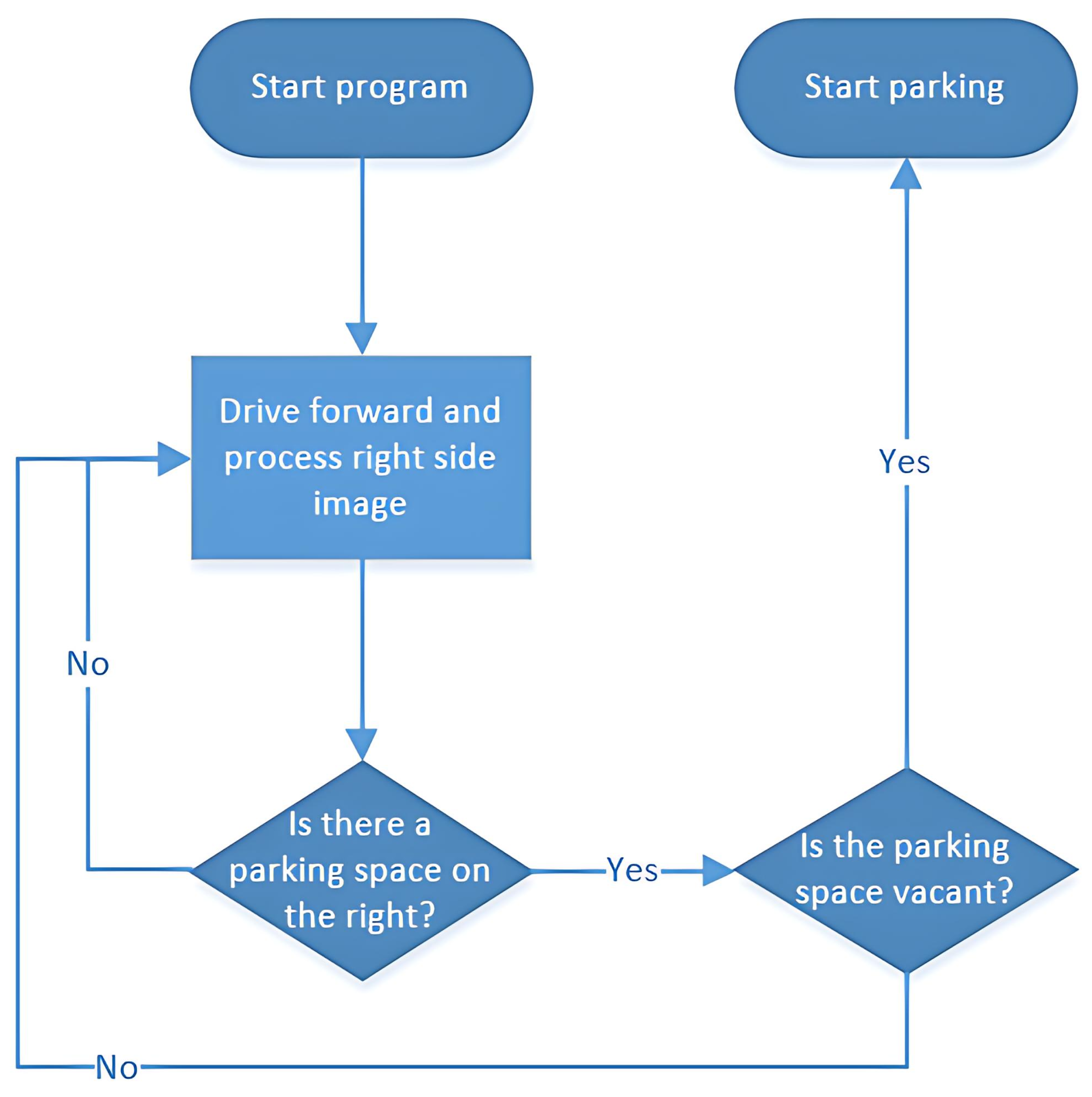
As illustrated in
Figure 1, the system integrates several key components: LiDAR, a Zed depth camera, a web camera, and two Arduino control boards. The overall architecture is organized into two main modules: perception and decision-making.
Figure 2 shows that all sensing operations and sensor data processing are handled by the onboard laptop. This includes identifying available parking spaces, detecting nearby obstacles, monitoring the vehicle’s offset while moving, and measuring the angle between the grid lines and the vehicle body after parking.
The control system manages all decision-making tasks, such as correcting the vehicle’s trajectory during movement, determining stopping points, initiating the parking process, making adjustments within the parking space, and avoiding obstacles.
The primary objective of this research is to seamlessly integrate perception and decision-making, enabling the vehicle to enter parking spaces both accurately and efficiently.
3. Image-Processing Analysis
Parking space detection in this system involves three main stages: capturing images, pre-processing those images, and detecting lines.
3.1. Image Data Pre-Processing
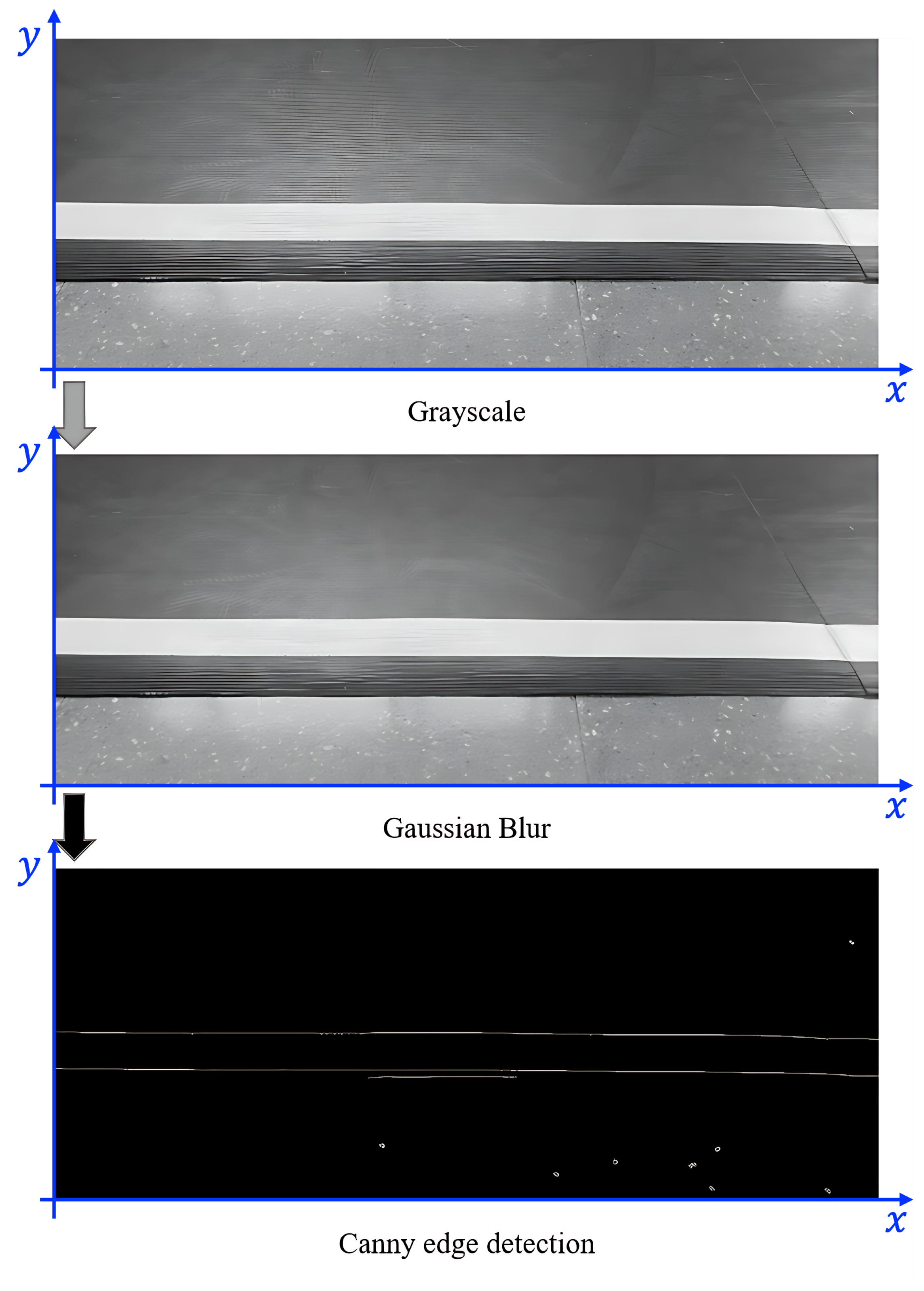
The camera operates at 60 frames per second, continuously capturing images as the vehicle moves. This enables the system to determine the vehicle’s position relative to the parking frame. To streamline processing and minimize detection errors, irrelevant portions of each image—typically the upper section, which often contains background elements like walls—are removed, leaving only the lower region that contains the area of interest.
Before analyzing the parking space, the images undergo pre-processing and noise reduction to reduce interference and potential errors. The pre-processing pipeline consists of two primary steps: converting images to grayscale and applying Gaussian smoothing. These steps accelerate image analysis and improve efficiency. To further enhance edge detection, the Canny algorithm is applied, allowing the system to accurately identify boundaries and filter out irrelevant brightness variations. This process improves the overall quality of image analysis. The results of image processing are shown in
Figure 3.
3.2. Line Detection for Parking Space Identification
The main objective of the automated parking system is to identify suitable parking spaces by analyzing images from the left-side camera to detect straight lines that outline the parking frame.
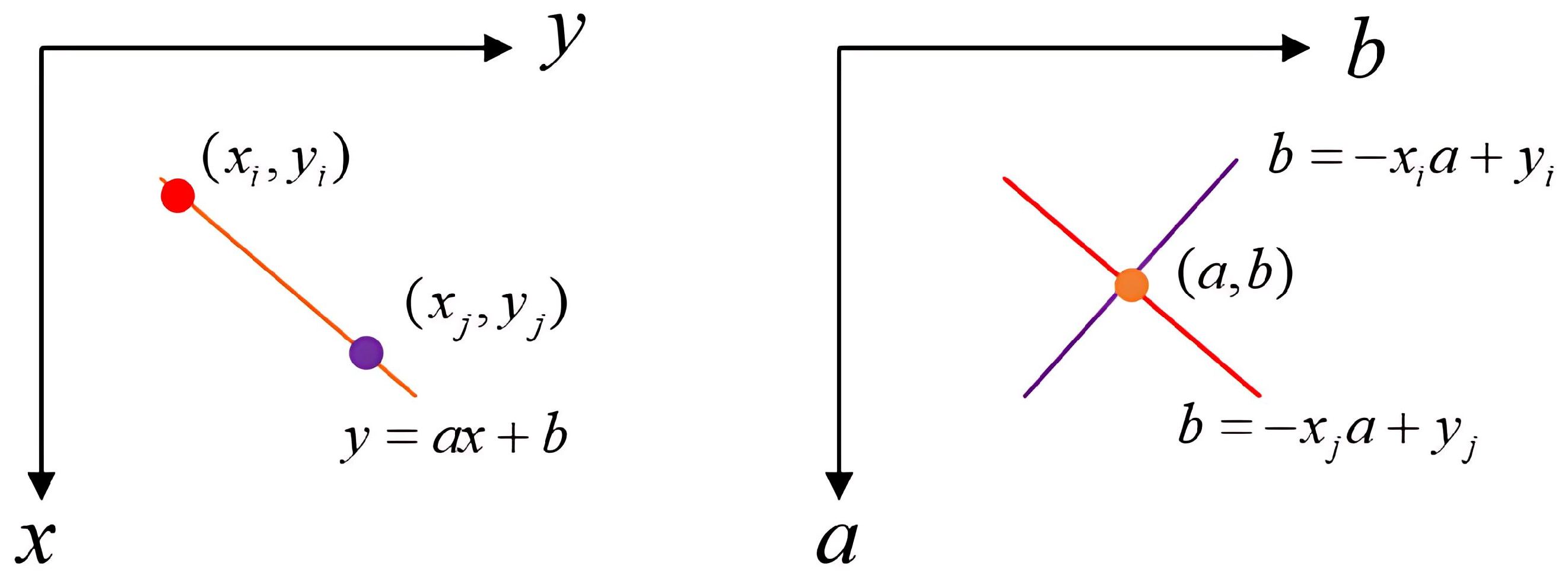
To accomplish this, the system uses the Hough transform, a widely adopted method for extracting features such as straight lines in image analysis. The Hough transform maps points from the image space to a parameter space, making it easier to detect linear features [
17]. After this transformation, the coordinates of straight lines in the original image can be determined, which supports subsequent parking maneuvers. The concept of the Hough transform is illustrated in
Figure 4. In this figure, the equation of a line is expressed as
Referring to
Figure 4, the points (red and purple) on a line in the original
image space correspond to intersections in the
parameter space. Using this principle, the image captured by the web camera is represented in
coordinates, and the detected straight lines—such as those of the parking frame—are mapped accordingly. Multiple straight lines in the parameter space will intersect at a single point, indicating the presence of a line in the image. After the transformation, the coordinates of the straight lines in the image can be determined.
The Hough transform is used to identify the
coordinates of the two endpoints of a straight line in the image, denoted as
and
. The slope
a of the line is then calculated as follows:
This information is essential for precise parking space identification and for guiding the vehicle’s subsequent maneuvers.
4. Automatic Parking System Design
In this automatic parking system, environmental data around the vehicle are gathered using three main sensors: a Zed depth camera mounted on the right side, a LiDAR sensor positioned above, and a web camera installed on the left-side mirror. All sensor inputs are processed by the onboard laptop, which interprets the information and transmits control commands to the vehicle’s motors via the control panel to enable automated parking.
The Zed depth camera is tasked with detecting the parking grid and determining the vehicle’s position within the parking space. When a suitable parking spot is identified on the right, the system signals the vehicle to stop and prepares for the next phase of the parking operation.
LiDAR is primarily used for obstacle avoidance and parking space detection. Beyond identifying vacant spots, LiDAR can also sense the presence of foreign objects or pedestrians in the parking area when the Zed camera detects an available space. If any obstacle is detected that could impede parking, the system pauses operations until the area is clear.
The web camera is mainly used for the alignment correction system. By referencing the right parking grid lines, the system calculates the angle between the grid lines and the vehicle. If the alignment falls outside the acceptable range, the system activates fine-tuning adjustments to ensure that the vehicle is properly positioned within the parking space.
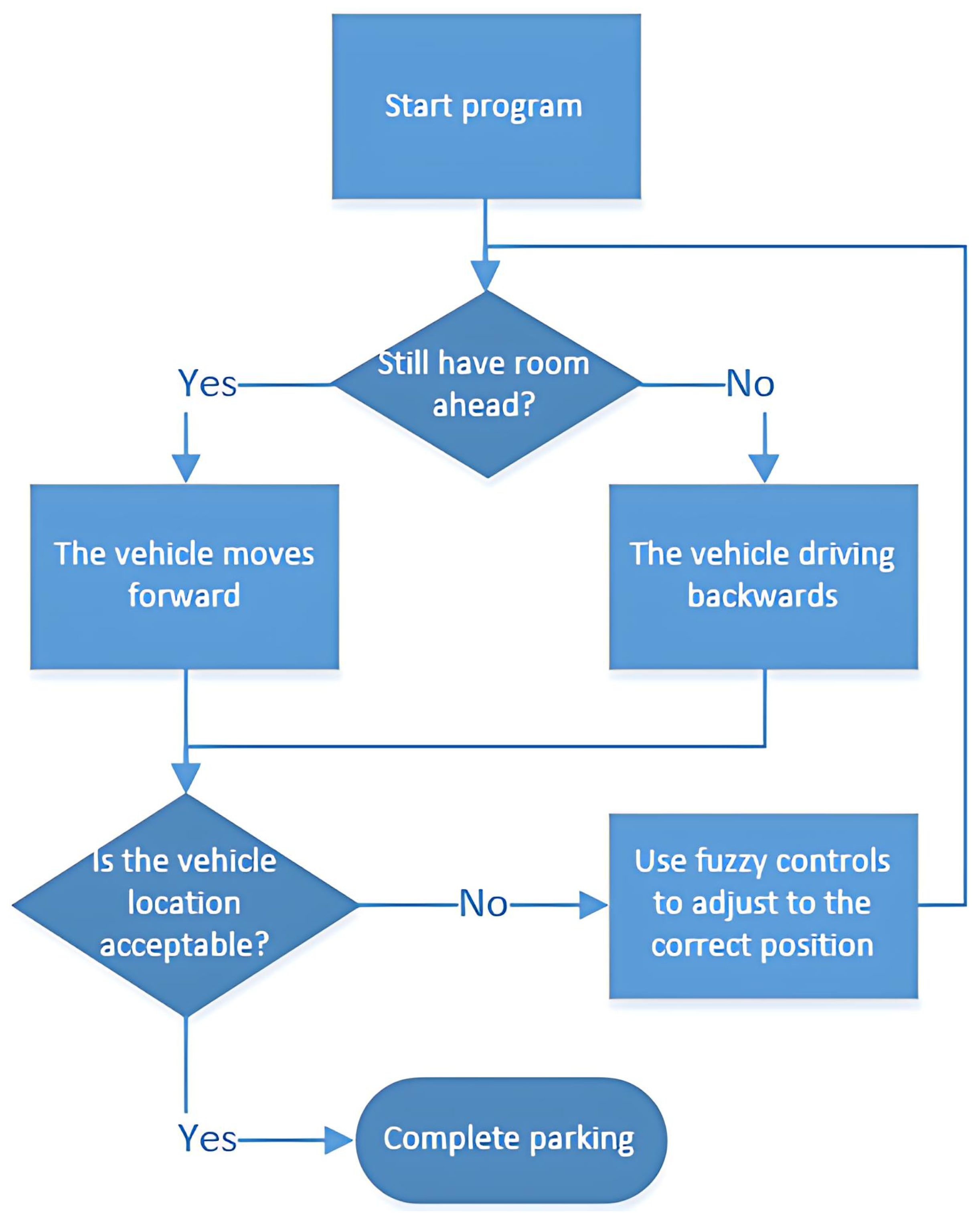
The overall workflow of the automatic parking system is illustrated in
Figure 5.
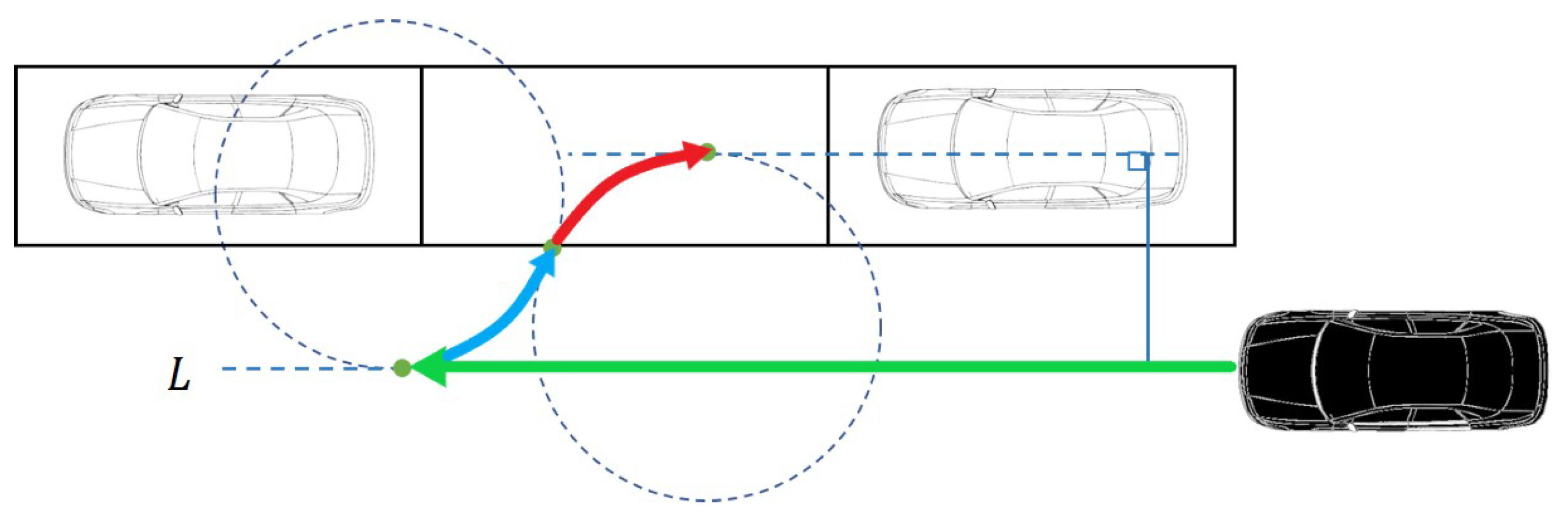
4.1. Parking Algorithm Using Minimum Turning Radius
In this automatic parking system, the vehicle’s steering angle is fixed to ensure precise parking space entry. The system employs two minimum turning radii to identify the optimal turning points during the parking maneuver [
18].
Using Ackermann steering geometry, the minimum turning radius
r is calculated as
where
is the wheelbase length and
represents the average steering angle derived from:
Here,
and
denote the maximum right and left steering angles, respectively.
The algorithm’s core functionality involves determining the precise turning positions to ensure smooth trajectory execution. This is achieved through the following steps:
Define the starting point and compute Circle I, centered at this position, with the minimum turning radius.
Define the destination point (final parking position) and compute Circle II, centered at this location, with the minimum turning radius.
Identify the tangent point between Circles I and II as the steering transition point. The vehicle adjusts its steering at this point and continues reversing to the destination.
Calculate the geometric coordinates for the starting point, destination point, and transition point.
Figure 6 illustrates this critical position determination process.
The vehicle follows path
L to reach the starting point tangent to Circle II, generating a two-segment parking trajectory. The complete path-planning algorithm is shown in
Figure 7.
4.2. Correction Program with Fuzzy Control
After executing the parking trajectory shown in
Figure 7, mechanical constraints may cause misalignment or wheel positioning errors within the parking grid. To ensure precise final positioning, a fuzzy control-based correction system is implemented.
The system uses the web camera on the left-side mirror as a reference sensor, analyzing the captured images to verify alignment accuracy. This fuzzy control approach avoids complex mathematical modeling while maintaining robustness, making it particularly effective given the challenges of analytically modeling vehicle misalignment dynamics. The correction workflow is illustrated in
Figure 8.
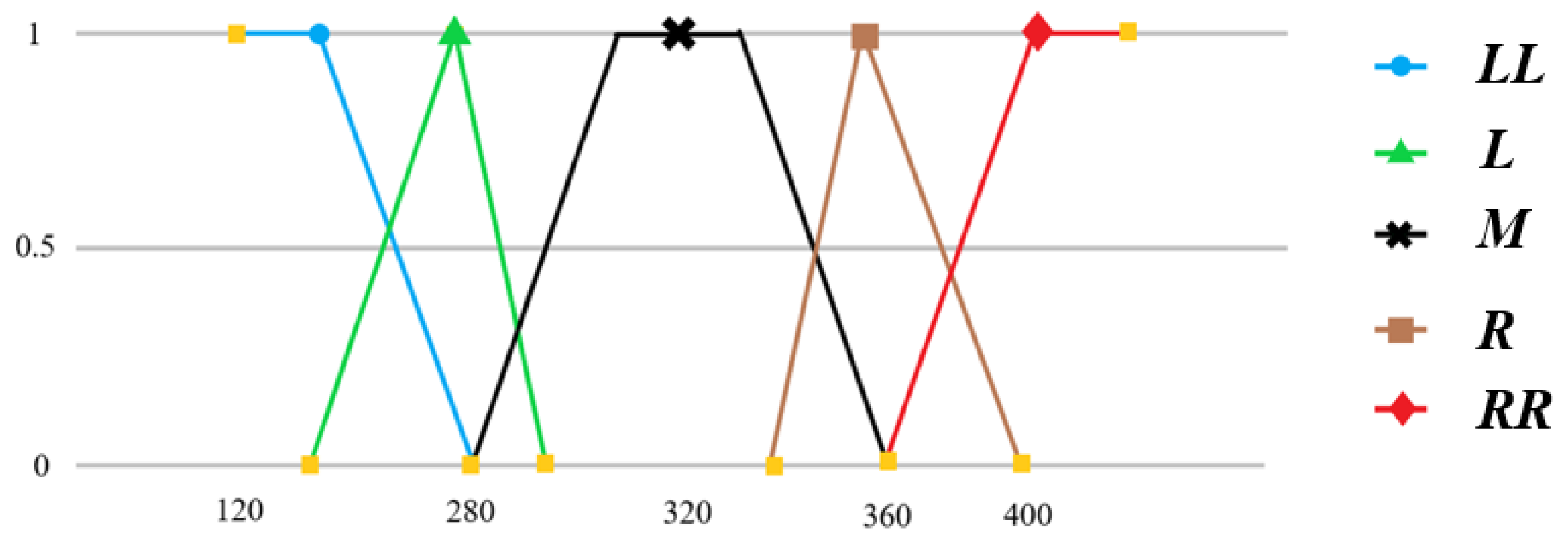
The system estimates the vehicle’s position relative to the parking space by analyzing the grid lines in processed images. After removing irrelevant regions, it extracts the target grid lines and calculates two parameters: the slope H (input to membership function ) and the lateral displacement S, obtained by fixing the y-axis at constant K and computing the x-coordinates where the lines intersect (input to membership function ).
Membership function is designed to quantify lateral displacement through five linguistic variables:
Severely left-shifted ();
Slightly left-shifted (L);
Centered (M);
Slightly right-shifted (R);
Severely right-shifted ().
The structure of
is shown in
Figure 9.
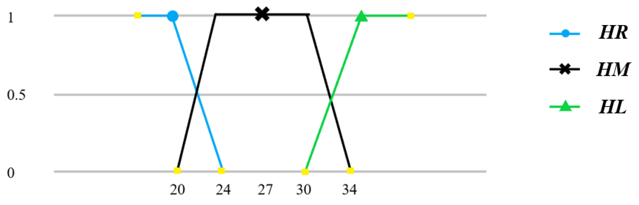
The system uses data from the web camera to evaluate angular deviation at the vehicle’s front. Following the image-processing methodology outlined earlier, the slope of the parking space lines is calculated and input into the fuzzy control system. This design allows the system to determine whether orientation correction is required.
Membership function
is defined using the calculated slope
H of the parking space lines, with three linguistic variables: front-right (
), front-center (
), and front-left (
). The structure of
is illustrated in
Figure 10.
The fuzzy control system employs seven correction rules (
,
R,
,
,
,
L, and
) to direct vehicle realignment.
Table 1 details the control actions associated with each rule.
The parameters of membership function
are dynamically adjusted based on the relative positions between the vehicle and the parking space. Experimental validation yielded an optimized fuzzy rule table (
Table 2), which enables faster convergence, smoother corrections, and stable performance.
Post-correction evaluations show substantial improvements in parking accuracy. The system achieves proper alignment within parking grids without detectable skewness, meeting practical parking requirements.
Development of Fuzzy Control Rules
The fuzzy control rules and membership functions used here were initially formulated based on expert knowledge of typical vehicle parking maneuvers and common misalignment scenarios. These rules were then empirically tuned through iterative testing on the model car platform. During experimentation, we observed the vehicle’s response to various misalignments and adjusted the rule base and membership function parameters to achieve robust and accurate alignment corrections. This hybrid approach—combining domain expertise with empirical validation—ensured that the fuzzy controller performed effectively under the constraints of the model vehicle.
4.3. Sensor Fusion Architecture
Briefly speaking, the system integrates data from the Zed depth camera, LiDAR, and web camera using a hybrid fusion approach. The Zed camera provides high-resolution depth maps for parking grid detection, while LiDAR delivers 360° spatial awareness for obstacle avoidance. The web camera monitors lateral alignment through visual grid lines. The sensor fusion process comprises the following components:
This architecture ensures robust perception while maintaining computational efficiency, critical for real-time operation on embedded hardware.
5. Experiments and Results
The experimental platform measures 70 cm in width and 110 cm in length, employing three primary sensors: a top-mounted LiDAR, a right-side Zed depth camera, and a web camera positioned above the right-side rear-view mirror. Sensor data are processed by an onboard laptop, which sends control commands to the Arduino Uno and Due boards for vehicle stopping and obstacle avoidance management.
The experimental configuration includes three parallel parking spaces placed adjacent to a wall, each measuring 86 cm in length and 140 cm in width. Two key test scenarios were evaluated:
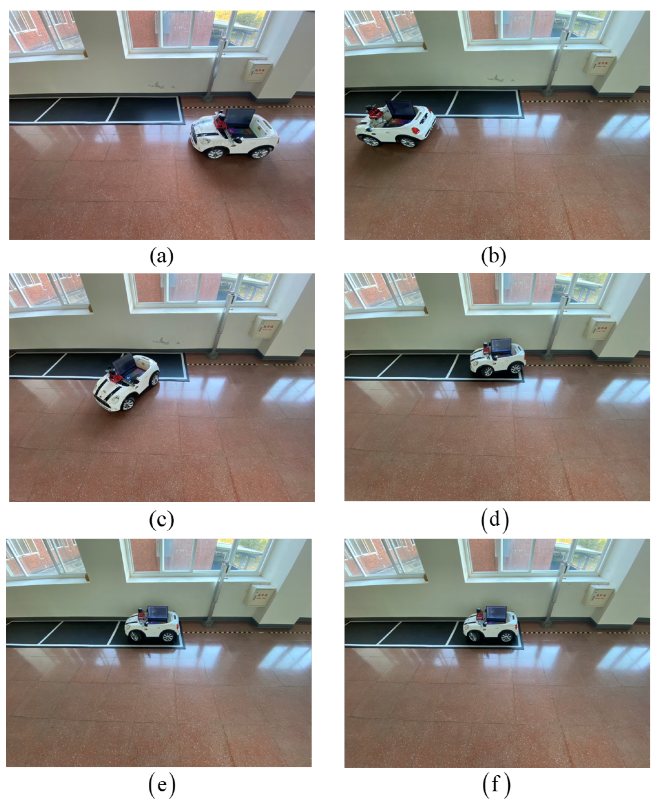
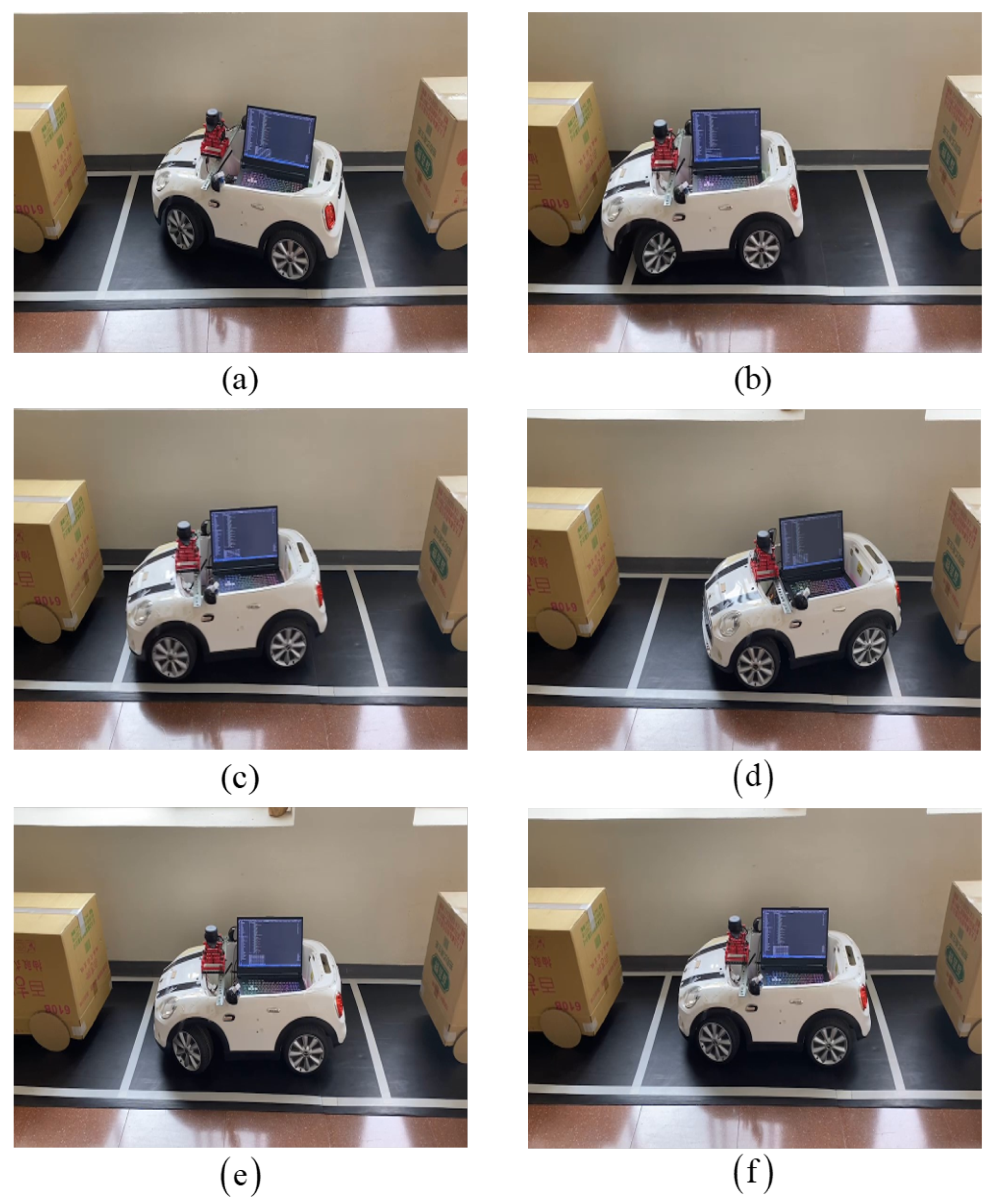
5.1. Automatic Parking
In the first scenario, the system autonomously guides the vehicle into the designated parking space. The complete sequence of this process is illustrated in
Figure 11a–f.
5.2. Position Correction After Parking
Following the initial parking maneuver, minor misalignments may still occur. To address this, the second scenario involves the system detecting any positional deviations using the web camera and subsequently applying fine-tuning corrections to ensure that the vehicle is accurately aligned within the parking grid. The correction outcomes are demonstrated in
Figure 12a–f.
At present, our evaluation is based primarily on visual inspection and qualitative analysis of the parking results, as illustrated in
Figure 11 and
Figure 12. Due to the limitations of our experimental setup and data-logging capabilities, we did not record time-series trajectory data or error metrics that would allow us to generate performance graphs such as recorded versus ideal trajectories, angular error evolution, or lateral deviation over time. We acknowledge that such quantitative plots would provide a more comprehensive assessment of system performance. In future work, we plan to incorporate detailed trajectory and error tracking to enable the inclusion of these performance graphs and a more thorough quantitative analysis.
6. Conclusions
This paper describes the design of an intelligent self-driving system for automatic parallel parking, integrating obstacle avoidance for enhanced safety. Once activated by the driver, the vehicle autonomously parks by leveraging a suite of sensors—including a roof-mounted LiDAR, a Zed depth camera, and a web camera—to continuously assess its environment. LiDAR provides a broad field of view for the rapid detection of parking spaces and potential hazards, while the depth and video cameras help the system perceive obstacles and ensure precise alignment, thereby improving safety for both the vehicle and surrounding road users.
Although the system demonstrated robust performance on a toy-scale platform, several challenges remain for real-world applications. During development, we encountered issues such as restricted steering angles, mechanical vibrations, and the need to synchronize multiple sensors on low-cost hardware, all of which required iterative tuning and empirical adjustments. Full-scale vehicles will face even greater sensor noise, more complex dynamics, and variable environmental conditions, such as changing lighting conditions, weather, and diverse parking markings. Additionally, the simplified actuation and limited steering of the model car do not fully capture real vehicle behavior, necessitating more advanced control strategies and sensor fusion.
To address these challenges and ensure reliable performance under practical conditions, future work will focus on adapting the fuzzy control logic and path-planning algorithms for full-size vehicles. This will involve using automotive-grade sensors to handle real-world noise and environmental variability, retuning control parameters for full-scale dynamics, and implementing robust safety mechanisms. These efforts aim to preserve the system’s real-time performance and reliability while enabling practical deployment in larger, real-world vehicles.


