Article

Research on Nonlinear Pitch Control Strategy for Large Wind Turbine Units Based on Effective Wind Speed Estimation

1
School of Automation, Wuhan University of Technology, Wuhan 430072, China
2
Three Gorges Intelligent Control Technology Co., Ltd., Wuhan 430070, China
*
Author to whom correspondence should be addressed.
Electronics 2025, 14(12), 2460; https://doi.org/10.3390/electronics14122460
Submission received: 15 May 2025 / Revised: 10 June 2025 / Accepted: 12 June 2025 / Published: 17 June 2025
(This article belongs to the Special Issue Power Electronics in Renewable Systems)

Abstract

:
With the increasing capacity of wind turbines, key components including the rotor diameter, tower height, and tower radius expand correspondingly. This heightened inertia extends the response time of pitch actuators during rapid wind speed variations occurring above the rated wind speed. Consequently, wind turbines encounter significant output power oscillations and complex structural loading challenges. To address these issues, this paper proposes a novel pitch control strategy combining an effective wind speed estimation with the inverse system method. The developed control system aims to stabilize the power output and rotational speed despite wind speed fluctuations. Central to this approach is the estimation of the aerodynamic rotor torque using an extended Kalman filter (EKF) applied to the drive train model. The estimated torque is then utilized to compute the effective wind speed at the rotor plane via a differential method. Leveraging this wind speed estimate, the inverse system technique transforms the nonlinear wind turbine dynamics into a linearized, decoupled pseudo-linear system. This linearization facilitates the design of a more agile pitch controller. Simulation outcomes demonstrate that the proposed strategy markedly enhances the pitch response speed, diminishes output power oscillations, and alleviates structural loads, notably at the tower base. These improvements bolster operational safety and stability under the above-rated wind speed conditions.

1. Introduction

In the context of the accelerating global energy transition, wind energy has emerged as the renewable energy source with the greatest potential for large-scale development, playing a pivotal role in achieving a sustainable energy transformation. According to the Global Wind Energy Report 2024 published in July 2017 [1], by the end of 2023, the global wind power installed capacity had surpassed 1000 GW, with onshore wind installations reaching a historic milestone by exceeding 100 GW in annual capacity additions for the first time—representing a remarkable 54% year-on-year growth.
As countries accelerate carbon neutrality initiatives, wind turbine technology is rapidly evolving towards gigawatt-scale systems and intelligent operation. However, the increasing mass of supersized wind turbines and excessive blade lengths introduce critical load-related challenges [2]. Furthermore, wind energy exhibits inherent intermittency, stochastic variability, and limited controllability as a non-dispatchable power generation source within electrical grids [3,4], compounded by the rotational inertia of massive turbine components and the nonlinear dynamics of pitch control systems (including rate limitations, hysteresis effects, and control delays) [5], which collectively hinder timely responses to wind speed variations. These technical constraints not only cause rotational speed overshoots and significant power fluctuations under extreme operating conditions but also induce structural vibrations that exacerbate tower load issues. In high-wind regions where power regulation and mechanical loading problems are particularly acute [6], manufacturers typically enhance the blade mechanical robustness through material overdesign, though this approach substantially escalates production costs. The effective implementation of nonlinear pitch control strategies offers a dual-benefit solution: achieving the simultaneous optimization of power regulation and load mitigation while reducing manufacturing costs and operational failures.
The wind speed data obtained from wind measurement radars is often integrated into the pitch control system of wind turbines to optimize the automated control strategy [7]. Refence [8] studied and analyzed the optimal distance of wind measurements by LiDAR and used radar-based wind speed feedforward control to reduce wind turbine loads. Reference [9] proposed an adaptive feedforward control algorithm for LiDAR-based on PI control, which improves the tracking speed and smoothes the output power fluctuation. Reference [10] used LiDAR-captured wind speed variations to implement an RBF neural network for the simultaneous optimization of the pitch angle and torque, addressing the objectives of power maximization and structural load mitigation. References [11,12,13] proposed a model predictive pitch control algorithm based on radar-measured wind using a linear or nonlinear model of wind turbines to improve the wind energy utilization factor of large wind turbines. Reference [14] compared radar-based linear and nonlinear predictive controls for pitch regulation, with the latter exhibiting an enhanced stabilization of the rotational speed and power output. Reference [15] examined the operational mechanisms of nacelle acceleration feedback versus lidar feedforward control. The results demonstrate that the LIDAR feedforward diminishes the rotor speed and thrust variability through pulsating load reductions. In contrast, nacelle feedback amplifies these effects. A combined implementation achieves a tower first-mode suppression alongside a decreased rotor speed and power fluctuations.
Highly accurate and wide-range LiDAR is used to measure wind speed, but the application of this technology significantly increases the installation and maintenance costs of large wind turbines [16], and wind speed estimation is gradually becoming a research focus as a low-cost means. Reference [17] employed support vector regression (SVR) to process and predict real-time wind speed data acquired by SCADA systems. The particle swarm algorithm was employed to optimize the SVR parameters in this process. Then, a feedforward controller for the pitch angle was designed based on the optimized SVR model to smooth the wind turbine output power and optimize wind turbine loads. Reference [18] firstly used an extended Kalman filter to estimate the wind speed in the past period of time and then used polynomial curve fitting to extrapolate the short-term predicted wind speed and optimized it using a neural network, and the results showed that the shorter the prediction time, the higher the accuracy. Reference [19] predicts the wind speed signal at the hub of a wind turbine by building a neural network physical model and wavelet analyzes it to filter out the high-frequency components to obtain a smooth low-frequency wind that plays a decisive role in wind speed predictions. Reference [20], addressing the vast number of wind turbines in wind farms and the intricate spatial and temporal correlation of wind speed, presented a correlation analysis method that integrates the whale optimization algorithm with the hybrid Copula function. On the foundation of conducting a correlation analysis on the wind speed of wind turbines, the study went on to establish a wind speed prediction model. Reference [21] proposed that Taylor’s turbulence freezing assumption neglects the evolution of the wind field structure, which will affect the accuracy of LiDAR wind measurements, so the autoregressive moving average with an exogenous input (Armax) model is used to model the wind evolution process and a particle swarm optimization algorithm is used to estimate the model parameters and finally predicted the effective rotor plane wind speed in advance based on the developed model. Reference [22] established the correlation between the tip–speed ratio, pitch angle, and power coefficient (Cp) via a Gaussian process regression using empirical wind turbine data, subsequently designing a wind speed estimator integrating this regression model with an extended Kalman filter. Reference [23] developed a turbulence intensity identification method using wind turbine operational data, established a simplified turbine model derived from the measured rotor speed and electromagnetic torque, and implemented an immersion-invariant observer for real-time wind speed estimations. Reference [24] introduced an adaptive neuro-fuzzy inference system with hybrid intelligent learning for online effective wind speed estimations, utilizing the real-time feedback of the tip–speed ratio, rotor speed, and mechanical power. References [25,26] employed an unknown input disturbance observer to accurately estimate the aerodynamic torque and utilized intelligent algorithms to approximate wind turbine aerodynamic characteristics. The effective wind speed at the rotor plane was subsequently determined from the measured rotor speed and pitch angle. This derived wind speed was integrated into the control loop to compute optimal control commands. Reference [27] included the rotor plane effective wind speed among the system dynamics to formulate the state space equation for the wind turbine. An extended Kalman filter was implemented to estimate this wind speed. Building upon the estimated wind speed, an adaptive model predictive controller (MPC) was developed. This design enhanced the system robustness and minimized power output fluctuations under high-wind-speed conditions. Reference [28] quantified the turbine structural deflection via Kalman filtering, thereby inferring the rotor plane effective wind speed from blade and tower bending characteristics.
Currently, an effective wind speed estimation is the primary means of reducing costs for large wind turbines, but it is primarily used in meteorology and has not been utilized to optimize control strategies. Therefore, this paper addresses power output fluctuations and overload issues in regions with high wind speeds. An effective wind speed estimation is performed under step and turbulent wind conditions, and an inverse system method is employed based on this estimation to design a nonlinear pitch control strategy. This significantly enhances the pitch system’s dynamic response, effectively mitigating speed and power fluctuations during high-wind operations while substantially reducing tower base load amplitudes. Simultaneously, the integration of the turbine output power with critical operational state parameters enables high-accuracy estimations of the rotor plane effective wind speed. This reduces the reliance on lidar and cuts system manufacturing costs directly. Additionally, the inverse system method’s low computational complexity results in lower hardware performance requirements for controllers during the engineering implementation. This significantly improves the pitch control quality without incurring hardware upgrade costs. This strategy enhances operational safety under extreme wind conditions and reduces maintenance costs for operators by alleviating structural fatigue.

2. Wind Turbine System Modeling

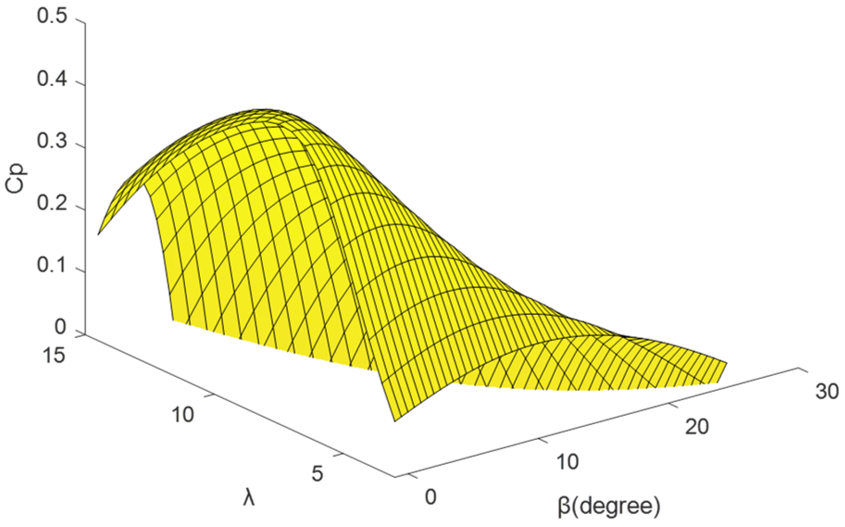
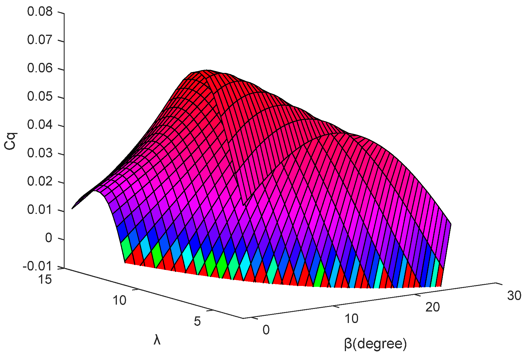
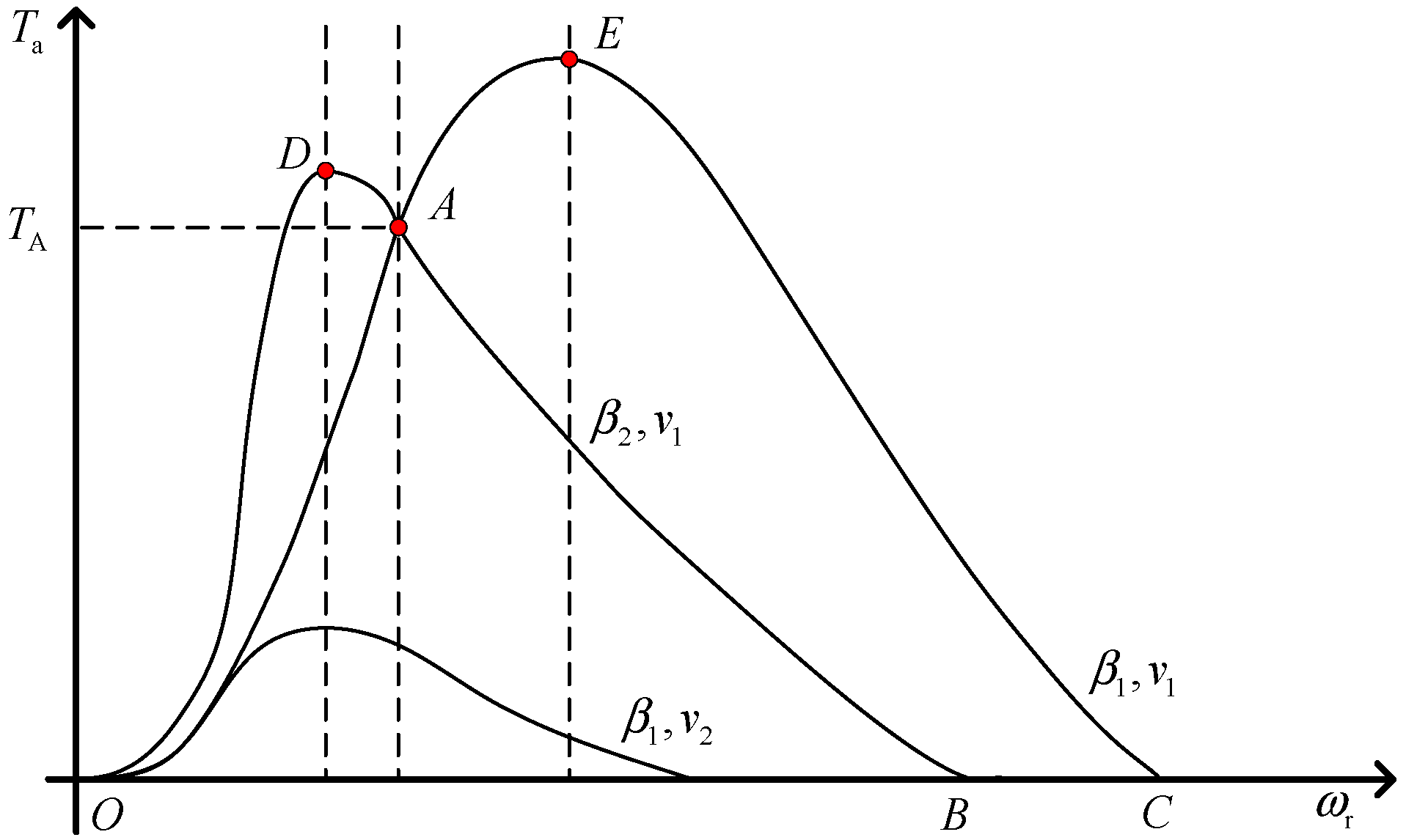
2.1. Wind Turbine Aerodynamic Modeling

The transformation of wind kinetic energy into electrical power within wind turbines is fundamentally governed by aerodynamic principles, but due to the complex computational problems involving the precise description of impeller geometric features and turbulence field resolution, a simplified model is usually used to characterize its energy conversion mechanism. The mathematical characterization of the model is as follows:
P = 1 2 C p ( λ , β ) ρ S v 3 λ = ω R v
where ω denotes the rotational mechanical angular velocity (rad/s) of the wind turbine, R represents the rotor radius, and Cp(λ,β) signifies the wind energy conversion coefficient. The determination of Cp involves multifaceted dependencies on the wind speed, rotor geometry, generator rotational speed, and blade pitch angle. During operational implementations, this coefficient is typically characterized by the following expression:
C p ( λ , β ) = 0.5176 116 λ i 0.4 β 5 e 21 λ i + 0.0068 λ 1 λ i = 1 λ + 0.08 β 0.035 β 3 + 1
The above equation represents, in detail, the relationship between the wind energy utilization factor Cp of the wind turbine with the blade tip speed ratio λ and pitch angle β, as shown in Figure 1.
An analysis reveals that the operational characteristics vary significantly at specific blade pitch angles β, and there exists a uniquely determined optimal tip speed ratio λopt corresponding to the corresponding maximum wind energy utilization coefficient Cpmax, which allows the wind turbine to capture the most energy, and therefore, the tip speed ratio can be maintained as a constant by controlling the wind turbine speed, which leads to a stable and efficient operation of the wind turbine.

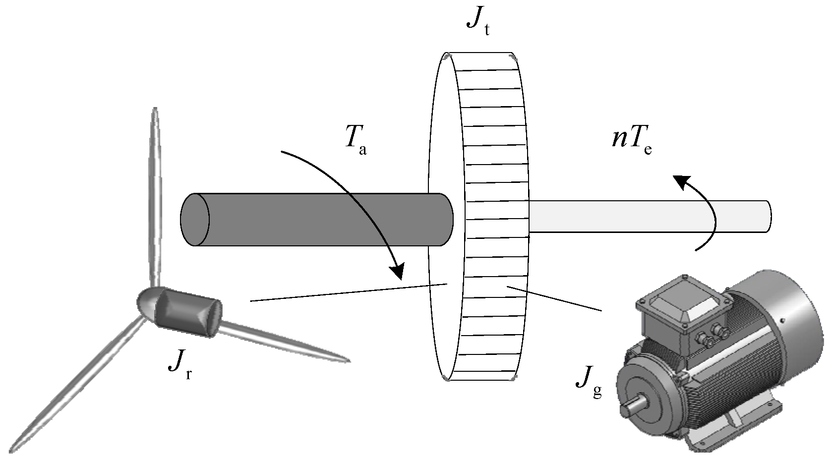
2.2. Wind Turbine Drive Train and Generator Modeling

In wind turbine drive train modeling, the system is typically conceptualized as multiple flexibly coupled rigid bodies. These representations are categorized as single-mass or multi-mass block models, depending on the number of rigid bodies in the system. In order to simplify the theoretical analysis and engineering calculations, this model adopts the equivalent inertia aggregation method: the equivalent inertia Jr on the low-speed side and the equivalent inertia Jg on the high-speed side are integrated and merged into a single equivalent inertia Jt that characterizes the overall characteristics of the drive system, and at the same time, the influence of the stiffness coefficient Cd and damping characteristics of the drive shaft system K is ignored, which results in the establishment of a single-block centralized parameter model as shown in Figure 2. While this omits high-frequency torsional oscillations, it retains a fidelity for pitch-dominated dynamics above the rated wind speed. Its operating equations are expressed as follows:
J t ω ˙ r = T a n T e
D r ω r + J r ω ˙ r = T a T ls D g ω g + J g ω ˙ g = T 1 s n T e T ls = K γ + C d γ ˙ γ = ω r ω g n

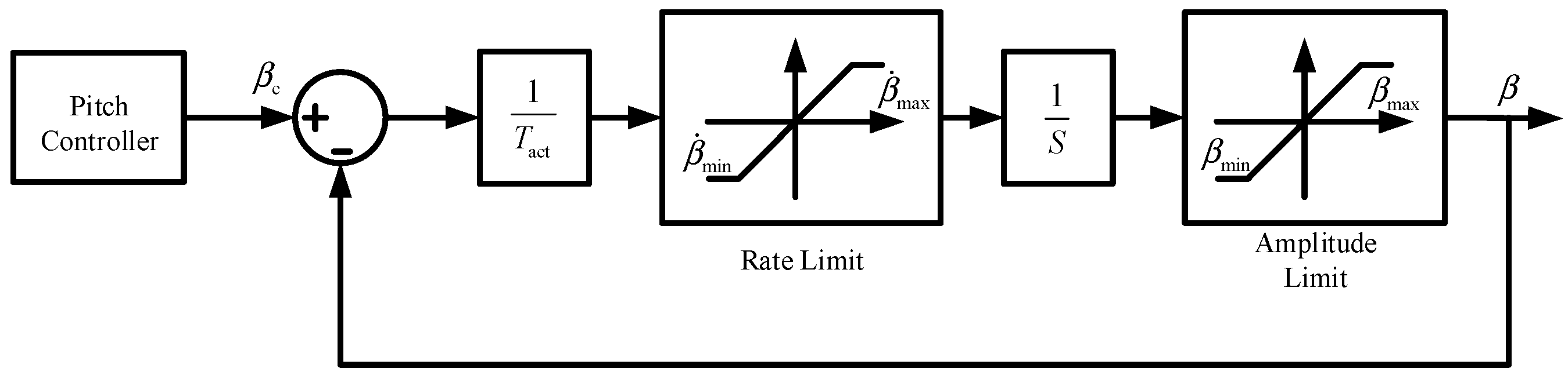
2.3. Modeling of Wind Turbine Pitch Systems

In large wind turbines, pitch actuators play an important role as an important component in all stages of operation. Due to the large inertia of the blades of a large wind turbine, there is a delay from the time the pitch controller issues a command to the time the actuator starts to perform its action. The time constant of this process is usually between 100 and 300 ms. Therefore, in the modeling process, the pitch actuator is usually equated to a first-order inertial link, whose transfer function can be expressed as follows:
β = k 1 T act s + 1 β c
where βc denotes the commanded pitch angle generated by the pitch controller, Tact represents the pitch actuator’s inertial time constant, and k1 signifies the gain of the inertial element, typically assigned a unit value.
Secondly, the pitch actuator also ensures the smooth operation of the wind turbine by limiting the amplitude and rate of the pitch change. The wind turbine pitch angle operates within a 0° to 90° range. The pitch rate varies by manufacturer specifications, with typical safety limits constrained to 6–8°/s. When the command value of the pitch angle exceeds the upper limit, the control command that exceeds the limit will not be responded to, so as not to cause adverse effects; the block diagram of the pitch actuator is shown in Figure 3.

3. Wind Speed Estimation Based on Extended Kalman Filtering

This paper utilizes the extended Kalman filter (EKF) algorithm to estimate aerodynamic torque. The effective wind speed at the rotor plane is subsequently computed via a differential approach.

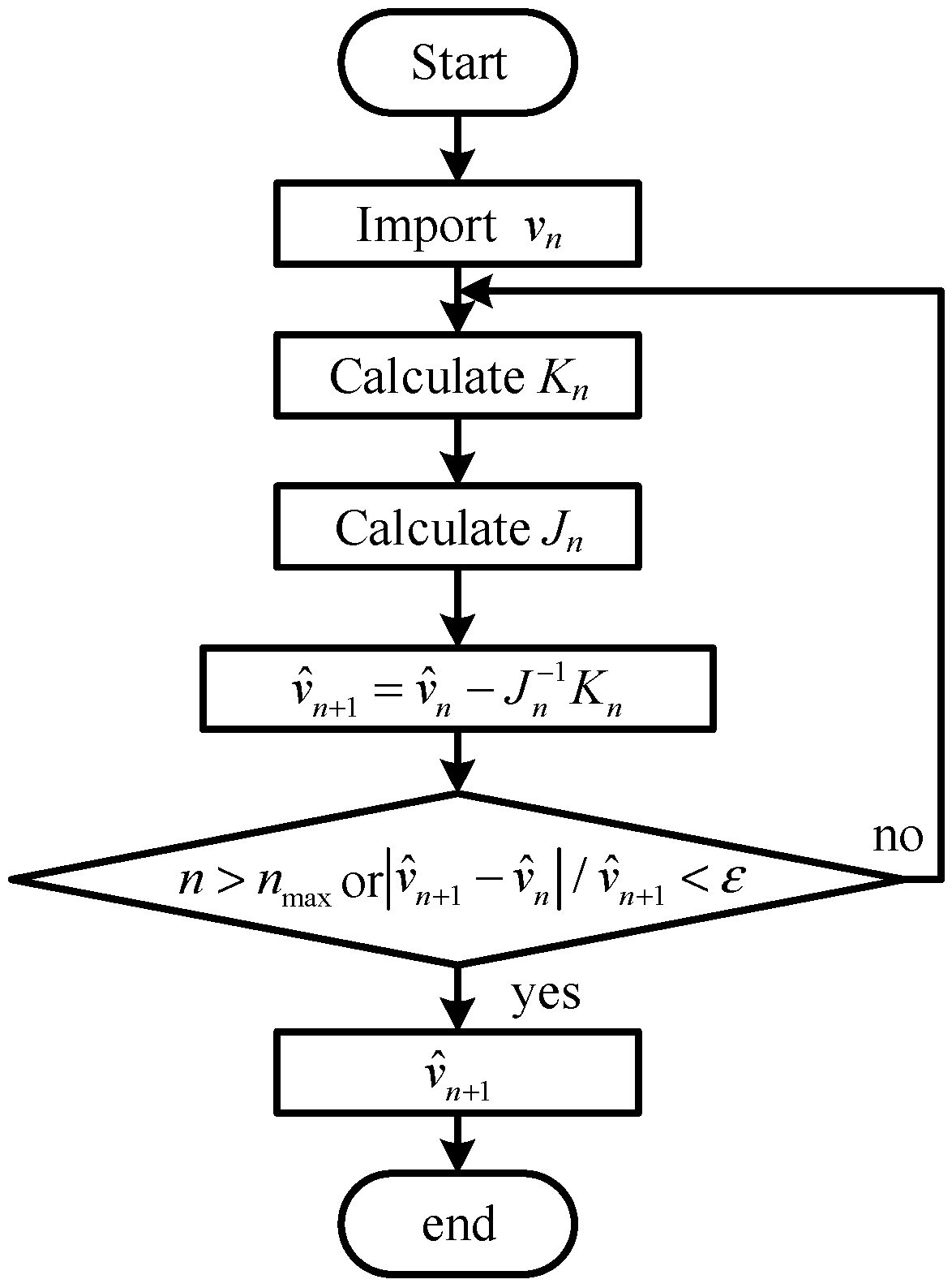
3.1. Extended Kalman Filter Theory

The extended Kalman filter is homologous to the classical Kalman filter in terms of its algorithmic architecture, which is divided into two parts: updating the timing and updating the measurements. Unlike the classical Kalman filter, the extended Kalman filter is a nonlinear approximation filter; i.e., it solves the nonlinear problem by local linearization on the basis of the classical algorithm. The extended Kalman filter can achieve better computational results when dealing with highly nonlinear systems, such as wind power systems. The prediction model of the extended Kalman filter can be expressed as follows:
x k + 1 = φ x k , k + Γ x k , k w k
z k + 1 = h x k + 1 , k + 1 + v k + 1
where k denotes the discrete moment; φ(xk, k) denotes the nonlinear state function; h(xk+1, k + 1) denotes the nonlinear measurement function; vk+1 denotes the measurement noise; wk denotes the process evolution noise; Γ(xk, k) denotes the output matrix of the process evolution noise; x denotes the nonlinear state vector; and z denotes the nonlinear measurement vector.
Applying a first-order Taylor expansion to the nonlinear state function derives the prediction equation:
x k + 1 φ x ^ k , k + φ x k x k = x ^ k x k x ^ k + Γ x ^ k , k w k                 = φ x k x k = x ^ k x k + φ x ^ k , k φ x k x k = x ^ k x ^ k + Γ x ^ k , k w k
x ^ k | k 1 = Φ k | k 1 x ^ k 1
P k | k 1 = Φ k | k 1 P k 1 Φ k | k 1 T + Γ k | k 1 Q k 1 Γ k | k 1 T
Φ k + 1 | k = φ x k x k = x ^ k
Expanding the nonlinear measurement function, h(xk+1, k + 1), via the first-order Taylor series updates the equation:
z k + 1 h x ^ k + 1 , k + 1 + h x k + 1 x k + 1 = x ^ k + 1 x k + 1 x ^ k + 1 + v k                 = h x k + 1 x k + 1 = x ^ k + 1 x k + 1 + h x ^ k + 1 , k + 1 h x k + 1 x k + 1 = x ^ k + 1 x ^ k + 1 + v k
K k = P k | k 1 H k T H k P k | k 1 H k T + R k 1
x ^ k = x ^ k | k 1 + K k z k H k x ^ k | k 1
P k = I K k H k P k | k 1 I K k H k T + K k R k K k T
H k + 1 = h x k + 1 x k + 1 = x ^ k + 1

3.2. Pneumatic Torque Estimation

Wind speed, as an external perturbation of the wind turbine, is difficult to integrate into the state space equations of the system to solve, so the aerodynamic torque is first estimated, and then the corresponding wind speed is calculated using the wind power curve. The aerodynamic torque, being solely governed by wind speed, is thus modeled via a first-order Markov process.
A Markov process is a class of stochastic processes, specifically for time series. If the probability of the present state depends only on the previous state, it is called a first-order Markov process, which is expressed in mathematical language as follows:
P S n = i n | S n 1 = i n 1 , , S 0 = i 0 = P S n = i n | S n 1 = i n 1
where Sn denotes the random variable S after the nth time step, and in represents the value of S taken.
Based on the above properties, we can get the value of the random variable taken at each moment:
P S n = i n , S n 1 = i n 1 , , S 0 = i 0 = P S n = i n | S n 1 = i n 1 P S 1 = i 1 | S 0 = i 0 P S 0 = i 0
Thus, the first-order Markov process for pneumatic torque can be expressed as follows:
T ˙ a = 1 T t T a + ε
where Tt is the time constant of the pneumatic torque, and ε is the Gaussian white noise.
Based on the equivalent two-mass block model of the drive chain, the desired equation of the motion of the drive train is obtained as follows:
ω ˙ r = T a J r C d γ ˙ + K γ J r ω ˙ g = C d γ ˙ + K γ N J g T e J g T ˙ a = T a T t γ ˙ = ω r ω g N
The corresponding state space equations are
X ˙ = A X + B U Y = C X + η
Among them
X = ω r ω g T a γ T
U = T e
A = C d J r C d N J r 1 J r K J r C d N J g C d N 2 J g 0 K N J g 0 0 1 T t 0 1 1 N 0 0
B = 0 1 J g 0 0 T
C = 1 0 0 0
where η is the measurement noise of the system. Taking the sampling period Ts = 0.001 s, using the bilinear transformation method to discretize the above state-space model, and considering the process noise of the system and the measurement noise of the sensor, the above expression is formalized as follows:
X ( k + 1 ) = A z X ( k ) + B z U ( k ) Y ( k ) = C z X ( k ) + D z U ( k )
Among them
A z = e A T = k = 0 A k T k k !
B z = 0 T e A τ d τ B = k = 0 A k T k + 1 ( k + 1 ) ! B

3.3. Wind Speed Estimation

Based on the extended Kalman filtering approach, the aerodynamic torque of the wind turbine, a strongly nonlinear system, has been accurately estimated in this paper. For the estimation of the effective wind speed, the Newton–Raphson algorithm has been used in the literature [29,30]. However, the wind turbine power curve is very complex and difficult to accurately represent by equations, making the derivation process in the Newton–Raphson algorithm challenging and prone to obtaining inaccurate results. This section implements a finite difference method approach to iteratively determine wind speed, eliminating derivational uncertainties in the solution process. The differential step size is set to 0.01 s. This value is determined through multiple trials and can strike a balance between the calculation accuracy and convergence speed, ensuring the stability of the iterative process and the accuracy of the results.
The expression of the wind turbine aerodynamic torque is given by
T a = P / ω r
The effective wind speed was computed iteratively using the following formulation:
V ^ ( t ) = argmin S ( t , v )
S ( t , v ) = ( T ^ ( t ) J ( v ) ) 2
where V ^ ( t ) denotes the optimal effective wind speed, T ^ ( t ) represents the Kalman-filtered aerodynamic torque estimate, J(v) defines the optimization criterion, and S(t,v) quantifies the variance between the estimated aerodynamic torque and the objective function.
The optimization criterion corresponds to the measured aerodynamic torque.
J ( v ) = T a
Ultimately, effective wind speed estimates are iteratively computed:
v ^ n + 1 = v ^ n J n 1 K n
where Jn denotes the discrepancy between the aerodynamic torque computed at the current wind speed and its Kalman-filtered estimate, combined with Kn, this yields the differential wind speed component:
J n = T ^ a 1 2 ρ π R 3 C p ( λ , β ) V 2 / λ
K n = ρ π R 3 v ^ n C p λ ^ n / λ + 1 2 ρ π ω ^ r R 4 C q λ ^ n λ
We repeat the above iterative process until the convergence condition is met and calculate the effective wind speed of the impeller surface. The flowchart of the algorithm is shown in Figure 4.

4. Nonlinear Pitch Control Strategy

The realization of the wind speed integration to the pitch control system can be mainly divided into two types of technical paths: one is to maintain the original closed-loop pitch control architecture on the basis of an external wind speed disturbance compensation mechanism to achieve feedforward control; the other is based on the dynamic model of the wind turbine reconfiguration of the entire closed-loop control strategy of the systematic design approach. Compared with the systematic design method that needs to reconstruct the control framework, the feedforward compensation scheme is widely used in engineering practice due to its unique robustness advantage—adjusting the system’s closed-loop pole distribution only through a perturbation compensation without changing the zero-point configuration, which fundamentally ensures the stability of the control system. This paper applies the inverse system control theory to develop a disturbance-compensating pitch strategy, leveraging a precise wind speed estimation via the inverse system method.

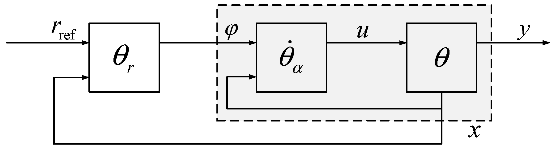
4.1. Fundamentals of Inverse Systems Theory Analysis

The inverse system method is a kind of method to convert a nonlinear system into a linear, decoupled standard form (i.e., pseudo-linear system) by constructing an “inverse system” model of the control object and then utilizing the design theory of the linear system to carry out the comprehensive design of the system. In the research field of nonlinear system control, the inverse system approach opens up completely new control strategies for researchers.
In general, for reversible systems, the steps to realize their inverse systems are as follows:
  • Find the inverse system Σ ^ of the original system Σ and its initial value.
  • Find the inverse of the α-order integral system Σ ^ α and its initial value.
  • Cascade the system Σ with its α-order integral inverse system to form a pseudo-linear composite system Σ Σ ^ α , which successfully decouples and linearizes the controlled object.
  • Considering each subsystem contained in the above pseudo-linear composite system Σ Σ ^ α as a controlled object, the design of the target control system is carried out by utilizing the design method of a single-variable linear system, such as the frequency response method or the root trajectory correction method.
Figure 5 shows the control loop designed based on the inverse system method.
Where rref is the reference value of the input signal, θr is the linear controller of the pseudo-linear system after cascading within the dotted box, θ ˙ α is its α-order derivative, u is the system input, y is the system output, and φ is the error.

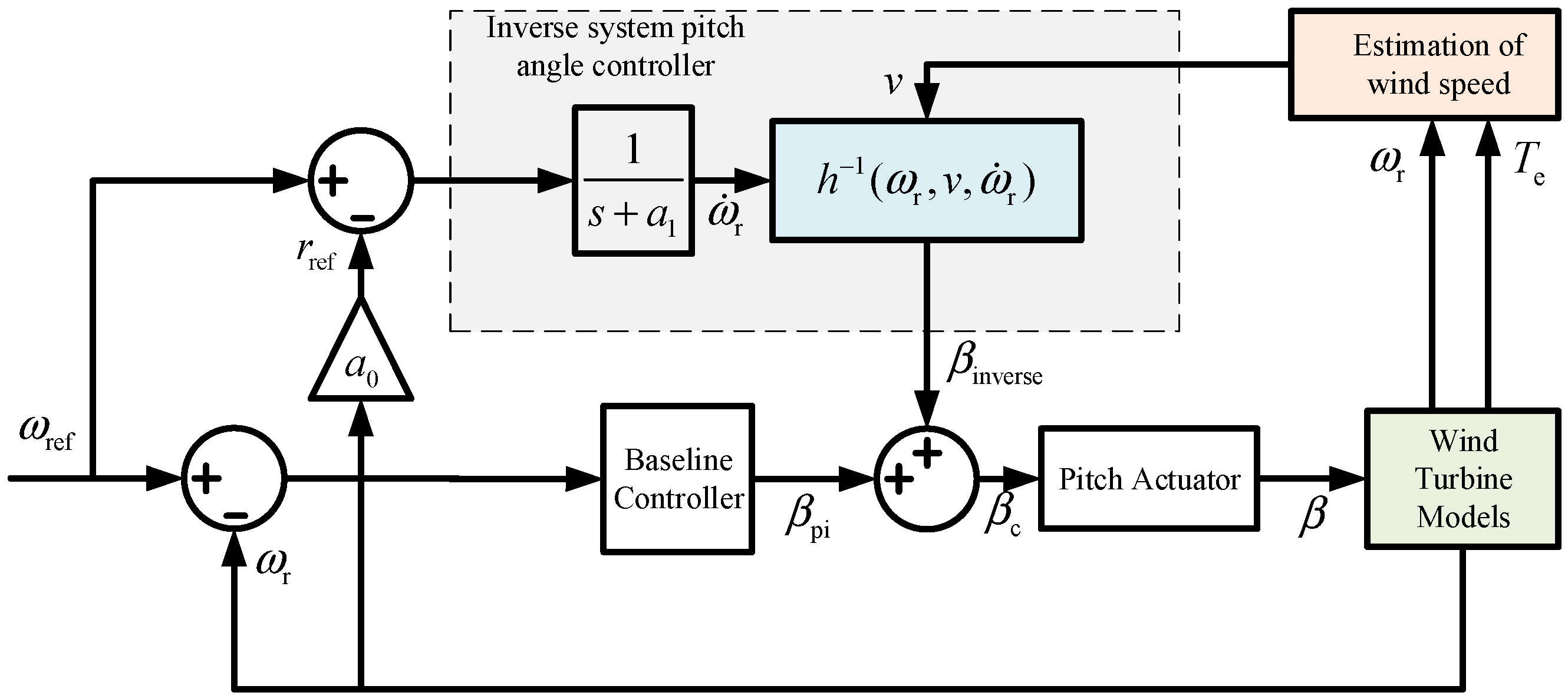
4.2. Pitch Controller Design

The large inertia of a large wind turbine causes the response speed of the electromagnetic torque and pitch control system to be much greater than that of the large wind turbine itself. The main manifestation is that the inertia lag time constant generated by the equivalent moment of the inertia Jt of the low-speed and high-speed axes of the drive chain far exceeds the time constant Tact of the pitch actuator and the electromagnetic time constant of the generator. In the singular regeneration theory, the system dynamics are divided into fast and slow two modes, ignoring the changes in the “fast mode” system, and it only studies the “slow mode” system; the fast system is considered to quickly enter the quasi-steady state [31], and the wind generator system model is downgraded and simplified to
ω ˙ r = 1 J t T ¯ a T ¯ e
T ¯ a = 1 2 C q ( λ , β c ) π R 3 ρ v 2
where T ¯ e represents the quasi-steady state value of the generator’s electromagnetic torque, then T ¯ a represents the quasi-steady state value of the aerodynamic torque; the value of which is determined by βc, which is the given value of the pitch angle before the pitch actuator.
Under the high-wind-speed section above the rated operating condition studied in this paper, the generator’s electromagnetic torque has reached its maximum value and cannot continue to increase, so the wind turbine speed is controlled only by changing the applied aerodynamic torque through the pitch, and the electrical dynamics of the generator’s electromagnetic torque can be neglected under this operating condition, i.e.,
T e = T ¯ e = K g T eN
where TeN is the rated electromagnetic torque of the generator.
Using the wind turbine rotational speed and its derivatives, the rotor-effective wind speed, and the previously estimated pitch angle input βc substituted into Equation (37) produces
β = h 1 ω r , v , ω ˙ r
This equation constitutes the inverse system for the reduced-order model (3–56).
Figure 6 shows the torque coefficient curve Cq for a wind turbine. If the blade tip speed ratio λ is certain, the relationship between Cq and the pitch angle β can be described by a parabolic equation in the two-dimensional plane. Thus, for a given Cq, there exists one to two values of β corresponding to it.
Continuing with the proof of the uniqueness of the above pitch angle solution, it is necessary to use the torque–speed curves of a typical pitch wind turbine system shown in Figure 7. In the figure, different pitch angles and wind speeds correspond to different curves, with a wind speed of v1 > v2 and pitch angle of β1 < β2. When the wind turbine operates at the intersection of curve ODB and curve OEC at A, it satisfies Ta = TA and ωr = ωA. At this point, at a certain wind speed and rotational speed—i.e., the above-mentioned wind turbine torque coefficient Cq is certain—there are two solutions for β, which are β1 and β2, respectively.
The analysis of the stability of the working point A shows that when the rotational speed ωr appears as a positive (negative) perturbation, the aerodynamic torque Ta on the curve segment OAE will increase (decrease) accordingly, and since the electromagnetic torque that reaches the limit value has been kept unchanged, it is known from the rotor motion equation that the rotational speed ωr continues to increase (decrease), which results in the system getting further and further away from the working point A. On the contrary, in the curve segment DAB, no matter whether the rotational speed ωr is increasing—or on the contrary, in the curve section DAB, no matter if the rotational speed ωr increases or decreases—the aerodynamic torque will always be opposite to the trend of its change, i.e., dTa/r < 0, thus suppressing the change in the rotational speed. In summary, there exists a unique stable inverse system of system (40), and its corresponding pitch angle can be derived from the current speed–torque curve of the wind turbine.
If system (39) is cascaded with its inverse system (40) to form a “pseudo-linear” system, as shown in the dashed box in Figure 8, it is possible to use a linear system analysis to dynamically configure the cascaded system.
Where ω ˙ r is the rate of change in the rotor speed, ωr is the rotor speed, v is the wind speed, h 1 ω r , v , ω ˙ r is the inverse system, βc is the pitch angle setpoint before the variable pitch actuator, and s is the Laplace operator.
ω ¨ r + a 1 ω ˙ r + a 0 ω r = r ( t )
where a1 and a0, determined via pole placement, yield the reference input rref = a0ωref for the inverse system pitch controller, and where ωref denotes the rated turbine speed. Figure 9 presents the proposed feedback-compensated control framework based on effective wind speed estimations within the inverse system methodology.
Where ωref is the rotor speed reference value, rref is the given inverse system pitch angle, v is the wind speed, ωr is the rotor speed, Te is the electromagnetic torque, ω ˙ r is the rotor speed change rate, h 1 ω r , v , ω ˙ r is the inverse system, a1 and a0 are the inverse system controller parameters, βpi is the PI controller output pitch angle value, βinverse is the inverse system output pitch angle value, βc is the pitch angle setpoint before the variable pitch actuator, and s is the Laplace operator.

5. Simulation Verification

To validate the feasibility of the control strategy, joint simulations are conducted using the FAST nonlinear wind turbine platform and Matlab/Simulink. FAST provides a variety of standard wind turbine models, and this paper adopts an onshore 5 MW large-scale wind turbine for the study. Its detailed parameters are shown in Table 1.

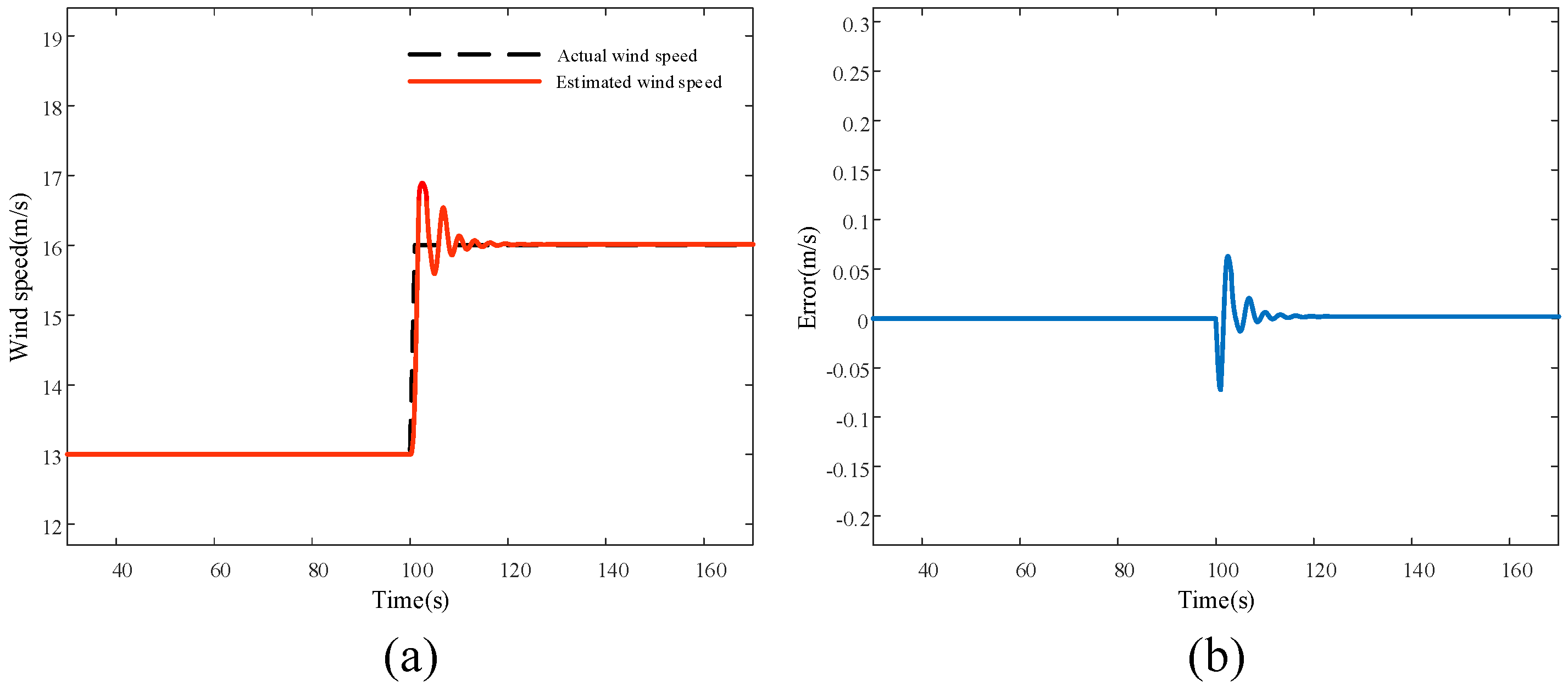
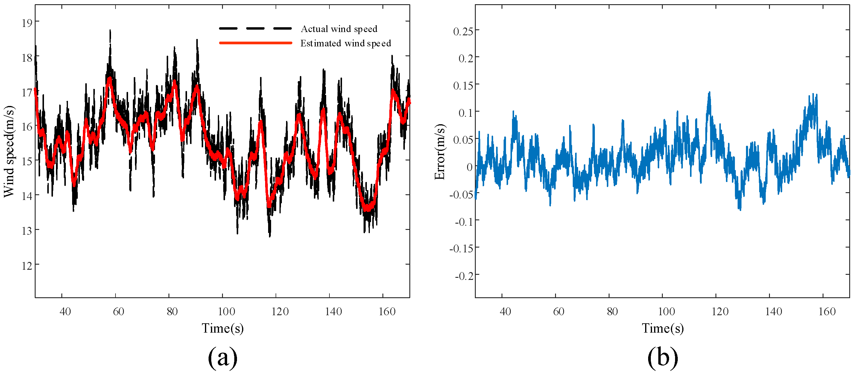
5.1. Simulation Results and Analysis of Wind Speed Estimation

In this section, firstly, the real-time estimation of the effective wind speed at the rotor plane of the wind turbine is carried out, and two wind conditions, the step wind changing from 13 m/s to 16 m/s and the turbulent wind with an average wind speed of 15 m/s and a turbulence degree of 10%, are selected for the experiment, where the actual wind speed is taken to be the wind speed captured at the hub in the FAST platform, and the maximum number of iterations in the iterative solution of the calculation of the effective wind speed nmax is taken to be 500 times, and the convergence condition ε is taken as 1 × 10⁻⁶; the errors of the estimated and actual wind speeds for the two wind conditions are shown in Figure 10a,b, where (a) is the comparison of the estimated wind speeds, and (b) is the estimation error.
When the wind speed changes, the pitch angle is limited by the rate of change, and it takes time from action to stabilization, which causes the rotational speed to fluctuate when the pitch angle changes. The effective wind speed iteration calculation needs to call the wind turbine torque coefficient curve to check the current rotational speed ω and pitch angle β corresponding to the value of the wind speed, while the rotational speed and pitch angle changes are closely related to the performance of the pitch controller. Figure 10a shows that the effective wind speed estimate lags behind the actual wind speed and has an error when the wind speed changes suddenly. Figure 10b shows that the error is up to 8% when the wind speed changes, and the error tends to be 0 when the wind speed is stable.
Figure 11b shows that there is no stable working point of the wind turbine in the turbulent wind field, and it is difficult to respond to the high-frequency component of the wind speed, so the error between the estimated effective wind speed and the actual wind speed is very large in high-frequency changes, close to 15%; in the low-frequency wind speed changes that the wind turbine can respond to, the error stabilizes at about 5%. It can be seen that the effective wind speed estimation algorithm proposed in this paper can better estimate the actual wind speed at the hub of the wind turbine.

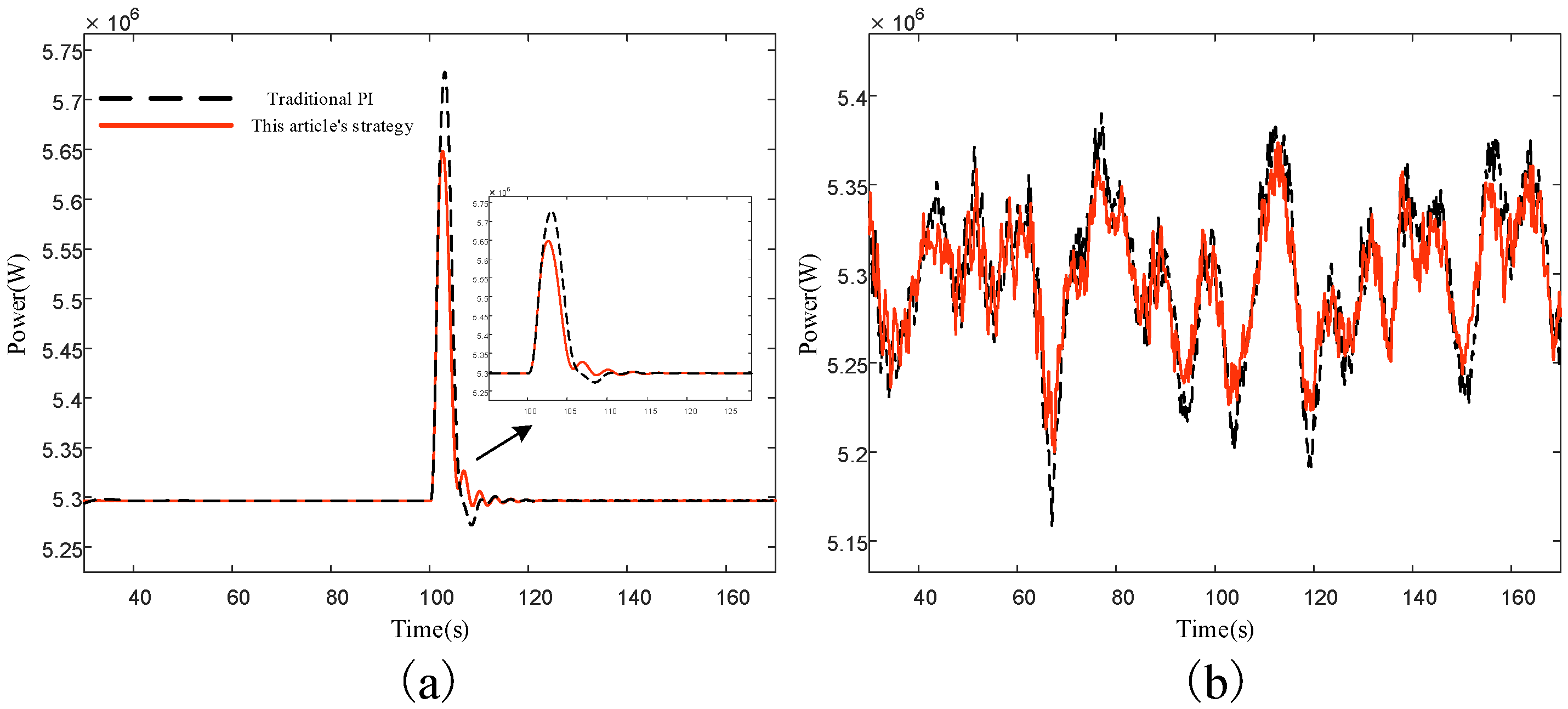
5.2. Pitch Control Simulation Results and Analysis

To assess the performance of the effective wind speed estimation-based inverse system pitch control, simulations were performed under both wind scenarios. Figure 12 presents the corresponding pitch angle variations, with (a) step-change and (b) turbulent wind conditions.
As shown in Figure 12a, the pitch angle adjusts 30% faster than conventional control under step-changing winds. Figure 12b reveals an enhanced wind speed tracking in turbulent conditions. Therefore, the feedback compensation pitch control loop that incorporates the inverse system method based on effective wind speed estimations can improve the response speed of the pitch control system to a certain extent, compared with traditional pitch controllers based on speed feedback.
Figure 13, Figure 14 and Figure 15 present the simulated wind turbine speed, generator output power, and tower bottom pitching moment under both wind conditions, with (a) step-change and (b) turbulent scenarios.
From the above simulation results, it can be seen that the evaluation criteria for the control effect are different between the step wind condition and turbulent wind condition. Therefore, the rated power and the tower bottom pitching moment before the step wind are used as the benchmarks to calculate the overshooting amount when the step wind arrives and as the evaluation index to judge the control effect; in the turbulent wind condition, the mean squared deviation (MSD) of the output power and the tower bottom pitching moment during the simulation time are used as the evaluation index for the control effect; in the turbulent wind condition, the mean squared deviation of the output power and tower bottom pitching moment during the simulation time are used as the evaluation index for the control effect. In turbulent wind conditions, the mean square difference between the output power and the tower bottom pitching moment during the simulation time is used as the evaluation index of the control effect.
Table 2 and Table 3 present comparative data on the output power and tower bottom pitching moment between the proposed method and traditional PI control, corresponding to step and turbulent wind conditions, respectively.
Figure 13 demonstrates that the inverse system-based feedback-compensated pitch control (utilizing the effective wind speed estimation) reduces the wind turbine speed overshoot during sudden wind changes more effectively than the conventional control, due to faster pitch responses in both step and turbulent conditions. The simulation results in Figure 14 reveal a reduced generator power overshoot under step winds and a closer alignment with rated values in turbulent winds, enhancing the power smoothness and grid delivery quality. As shown in Figure 15, the proposed strategy decreases the wind thrust on turbines during wind transients by improving the pitch response speed, achieving a tower base load reduction.
From Table 2 and Table 3, we can observe the specific data, under the step wind condition, and in the method proposed in this paper the output power of the overshoot decreased by 22%, compared to the traditional pitch control in the bottom of the tower pitching moment, and the overshoot decreased by 17%, with an obvious output power smoothing and load shedding effect; the turbulent wind conditions, related to the mean square deviation as an evaluation index, also significantly demonstrate the advantages of the method proposed in this paper. Table 4 qualitatively compares the proposed pitch control strategy with the conventional PI control across critical performance metrics.

6. Conclusions

This study presents a nonlinear pitch control strategy based on an effective wind speed estimation designed to enhance the operational stability of wind turbines operating under complex above-rated wind speed conditions. The core objective is the mitigation of power fluctuations and the prevention of structural overloads. The strategy achieves this by integrating the real-time effective wind speed estimation, derived via a differential computation following aerodynamic torque estimations using an extended Kalman filter applied to the drivetrain, with an inverse system methodology for the pitch angle synthesis. This integrated approach enables the determination of the optimal real-time pitch angle based on the rotor plane wind speed estimation.
Simulation results substantiate the efficacy of the proposed control system. The strategy demonstrates an enhanced pitch system response, effectively suppressing fluctuations in both the rotational speed and power output within high-wind-speed regimes. Furthermore, a significant reduction in the tower base loading is achieved. Collectively, these improvements enhance operational safety during extreme wind conditions and reduce long-term maintenance costs by mitigating structural fatigue damage. The strategy also holds the potential to lower manufacturing expenses by diminishing the necessity for overdesigned turbine components.
The core advantages of the control strategy proposed in this paper, including the stable power regulation and structural load alleviation, have been successfully validated through simulations encompassing both step and turbulent wind inputs. Future work will focus on bridging the gap between the simulation and practical application by implementing and testing the proposed control framework on the wind turbine under real-world environmental conditions.

Author Contributions

Methodology, L.L.; Software, Y.L.; Validation, L.L.; Formal analysis, L.L.; Investigation, Y.L. and R.C.; Resources, Y.L. and R.L.; Data curation, Z.C.; Writing—original draft, L.L.; Writing—review & editing, L.L. and X.D.; Supervision, X.D.; Project administration, H.W.; Funding acquisition, X.Y. All authors have read and agreed to the published version of the manuscript.

Funding

This work is supported by the Hubei Provincial Key Research and Development Program Project (2023DJC201) and the Three Gorges Intelligent Control Technology Co., Ltd. Research Project (TGIC-KY-2024-04-00).

Data Availability Statement

The data that support the findings of this study are available on request from the corresponding author. The data are not publicly available due to privacy or ethical restrictions.

Acknowledgments

We thank the editor and the anonymous reviewers for their constructive comments that helped to improve our work.

Conflicts of Interest

Author Xuxin Yue, Haoran Wang, Ruibo Liu, Zhaobing Cai and Ruiqi Cai were employed by the company Three Gorges Intelligent Control Technology Co., Ltd. The remaining authors declare that the research was conducted in the absence of any commercial or financial relationships that could be construed as a potential conflict of interest.

References

  1. GWEC. Global Wind Report 2024; Global Wind Energy Council: Abu Dhabi, United Arab Emirates, 2024. [Google Scholar]
  2. Alhrshy, L.; Lippke, A.; Jauch, C. Variable Blade Inertia in State-of-the-Art Wind Turbine Structural-Dynamics Models. Energies 2023, 16, 6061. [Google Scholar] [CrossRef]
  3. Lu, P.; Shi, Y.P. China’s wind power industry enters a stage of high-quality market-oriented development. Wind Energy 2023, 5, 72–76. [Google Scholar]
  4. Wan, Y. Cooperative Control for DFIG-Based Wind Turbine Generation System Covering All Operating Regions. IEEE Trans. Sustain. Energy 2025, 16, 945–954. [Google Scholar] [CrossRef]
  5. Lasheen, A.; Elshafei, L.A. Wind-turbine collective-pitch control via a fuzzy predictive algorithm. Renew. Energy 2016, 87, 298–306. [Google Scholar] [CrossRef]
  6. Abdin, E.S.; Xu, W. Control design and dynamic performance analysis of a wind turbine-induction generator unit. IEEE Trans. Energy Convers. 2000, 15, 91–96. [Google Scholar] [CrossRef]
  7. Scholbrock, A.; Fleming, P.; Schlipf, D.; Wright, A.; Johnson, K.; Wang, N. Lidar-enhanced wind turbine control: Past, present, and future. In Proceedings of the 2016 American Control Conference (ACC), Boston, MA, USA, 6–8 July 2016; pp. 1399–1406. [Google Scholar]
  8. Haizmann, F.; Schlipf, D.; Raach, S.; Scholbrock, A.; Wright, A.; Slinger, C.; Medley, J.; Harris, M.; Bossanyi, E.; Cheng, P.W. Optimization of a feed-forward controller using a CW-lidar system on the CART3. In Proceedings of the 2015 American Control Conference, Chicago, IL, USA, 1–3 July 2015; pp. 3715–3720. [Google Scholar]
  9. Wang, N.; Johnson, K.E.; Wright, A.D. FX-RLS-Based Feedforward Control for LIDAR-Enabled Wind Turbine Load Mitigation. IEEE Trans. Control. Syst. Technol. 2012, 20, 1212–1222. [Google Scholar] [CrossRef]
  10. Han, B.; Zhou, L.; Zhang, Z. LIDAR-assisted radial basis function neural network optimization for wind turbines. IEEJ Trans. Electr. Electron. Eng. 2018, 13, 195–200. [Google Scholar] [CrossRef]
  11. Mirzaei, M.; Soltani, M.; Poulsen, N.K.; Niemann, H.H. An MPC approach to individual pitch control of wind turbines using uncertain LIDAR measurements. In Proceedings of the 2013 European Control Conference (ECC), Zurich, Switzerland, 17–19 July 2013; pp. 490–495. [Google Scholar]
  12. Mirzaei, M.; Hansen, M.H. A LIDAR-assisted model predictive controller added on a traditional wind turbine controller. In Proceedings of the 2016 American Control Conference (ACC), Boston, MA, USA, 6–8 July 2016. [Google Scholar]
  13. Schlipf, D.; Pao, L.Y.; Cheng, P.W. Comparison of feedforward and model predictive control of wind turbines using LIDAR. In Proceedings of the 2012 IEEE 51st IEEE Conference on Decision and Control (CDC), Maui, HI, USA, 10–13 December 2012; pp. 3050–3055. [Google Scholar]
  14. Schlipf, D.; Grau, P.; Raach, S.; Duraiski, R.; Trierweiler, J.; Cheng, P.W. Comparison of linear and nonlinear model predictive control of wind turbines using LIDAR. In Proceedings of the 2014 American Control Conference, Portland, OR, USA, 4–6 June 2014; pp. 3742–3747. [Google Scholar]
  15. Atsushi, Y.; Iman, Y.; Takeshi, I. Reduction in the Fluctuating Load on Wind Turbines by Using a Combined Nacelle Acceleration Feedback and Lidar-Based Feedforward Control. Energies 2020, 13, 4558. [Google Scholar] [CrossRef]
  16. Li, D.Y.; Cai, W.C.; Li, P.; Jia, Z.J.; Chen, H.J.; Song, Y.D. Neuroadaptive Variable Speed Control of Wind Turbine with Wind Speed Estimation. IEEE Trans. Ind. Electron. 2016, 63, 7754–7764. [Google Scholar] [CrossRef]
  17. Jiao, X.; Yang, Q.; Xu, B. Hybrid Intelligent Feedforward-Feedback Pitch Control for VSWT with Predicted Wind Speed. IEEE Trans. Energy Convers. 2021, 36, 2770–2781. [Google Scholar] [CrossRef]
  18. Hur, S.H. Short-term wind speed prediction using Extended Kalman filter and machine learning. Energy Rep. 2020, 7, 1046–1054. [Google Scholar] [CrossRef]
  19. Gao, Y.; Zhong, H.Y.; Chen, X.Y.; Geng, A.C.; Zhang, L.; Lei, C.J. Ultra-short-term wind speed prediction based on neural network and wavelet analysis. Renew. Energy 2016, 34, 705–711. [Google Scholar]
  20. Wang, D.F.; Zhang, Z.Y.; Gu, Z.Y.; Huang, Y. Wind farm wind speed prediction based on hybrid Copula function and whale optimization algorithm. Electr. Power Sci. Eng. 2022, 38, 33–40. [Google Scholar]
  21. Cao, S.Q.; Hao, W.J.; Wang, H.; Sun, Z.H.; Zhou, J.Y. Effective wind speed prediction at wind turbine hub based on LiDAR-Armax. Laser Optoelectron. Prog. 2020, 57, 228–234. [Google Scholar]
  22. Hou, W.L.; Ang, L.; Fan, Z.M. Real-time rotor effective wind speed estimation using Gaussian processregression and Kalman filtering. Renew. Energy 2021, 169, 670–686. [Google Scholar]
  23. Wang, Y.Z.; Cai, X.; Wu, A.; Xu, B.F.; Lin, S.F. Turbulence intensity identification and load reduction of wind turbine under extreme turbulence. Ocean. Eng. 2022, 257, 111710. [Google Scholar] [CrossRef]
  24. Asghar, A.B.; Liu, X. Adaptive neuro-fuzzy algorithm to estimate effective wind speed and optimal rotor speed for variable-speed wind turbine. Neurocomputing 2018, 272, 495–504. [Google Scholar] [CrossRef]
  25. Deng, X.; Yang, J.; Sun, Y.; Song, D.; Xiang, X.; Ge, X.; Joo, Y.H. Sensorless effective wind speed estimation method based on unknown input disturbance observer and extreme learning machine. Energy 2019, 186, 115790. [Google Scholar] [CrossRef]
  26. Deng, X.; Yang, J.; Sun, Y.; Song, D.; Yang, Y.; Joo, Y.H. An effective wind speed estimation based extended optimal torque control for maximum wind energy capture. IEEE Access 2020, 8, 65959–65969. [Google Scholar] [CrossRef]
  27. Tian, D.; Zhou, C.K.; Tang, S.Z.; Zhou, Q.; Huang, M.Y.; Deng, Y. MPPT method for large wind turbines based on adaptive model predictive control. Acta Energiae Solaris Sin. 2023, 44, 501–508. [Google Scholar]
  28. Simley, E.; Pao, Y.L. Evaluation of a wind speed estimator for effective hub-height and shear components. Wind Energy 2016, 19, 167–184. [Google Scholar] [CrossRef]
  29. He, Y.L.; Huang, S.; Du, J.; Su, D.X.; Li, J. Feedforward-based pitch control for wind turbines. Power Syst. Prot. Control 2012, 40, 15–20. [Google Scholar]
  30. Wang, X.L.; Tang, H.M.; Bao, G.Q.; Zhang, X.Y.; Liang, C. Disturbance feedforward and predictive feedback composite control for load suppression in wind turbines. Trans. China Electrotech. Soc. 2016, 31, 230–235. [Google Scholar]
  31. Dai, S.Z. Singular perturbation theory. Syst. Eng. Electron. 1988, 2, 1–12. [Google Scholar]
Figure 1. Wind energy utilization factor.
Electronics 14 02460 g001
Figure 2. The equivalent single-mass block model of the driveline.
Electronics 14 02460 g002
Figure 3. Block diagram of pitch actuator.
Electronics 14 02460 g003
Figure 4. Effective wind speed iterative calculation process.
Electronics 14 02460 g004
Figure 5. The schematic diagram of the inverse system approach.
Electronics 14 02460 g005
Figure 6. Wind turbine torque coefficient curve.
Electronics 14 02460 g006
Figure 7. Wind turbine speed–torque curve.
Electronics 14 02460 g007
Figure 8. A schematic diagram of the inverse system approach to wind turbine modeling.
Electronics 14 02460 g008
Figure 9. Block diagram of pitch control based on inverse system method for effective wind speed estimation.
Electronics 14 02460 g009
Figure 10. Estimation of step wind speed. (a) Estimated wind speed. (b) Estimation error.
Electronics 14 02460 g010
Figure 11. Estimation of turbulent wind speed. (a) Estimated wind speed. (b) Estimation error.
Electronics 14 02460 g011
Figure 12. Comparison of pitch angle simulation results. (a) Step wind condition. (b) Turbulent wind conditions.
Electronics 14 02460 g012
Figure 13. Comparison of speed simulation results. (a) Step wind condition. (b) Turbulent wind conditions.
Electronics 14 02460 g013
Figure 14. Comparison of output power simulation results. (a) Step wind condition. (b) Turbulent wind conditions.
Electronics 14 02460 g014
Figure 15. Comparison of tower bottom pitching moment simulation results. (a) Step wind condition. (b) Turbulent wind conditions.
Electronics 14 02460 g015
Table 1. System design parameters.
NameParameters
Rated power5 MW
Number of blades3
Impeller diameter126 m
Hub diameter3 m
Cut-in wind speed3 m/s
Rated wind speed11.4 m/s
Cutting out wind speed25 m/s
Rated electromagnetic torque43,093.55 N·m
Rated speed12.1 rpm
Rotor mass110,000 kg
Blade initial pitch angle0 deg
Drive train damping6.22 × 106 N·m/(rad/s)
Drive train stiffness8.67 × 108 N·m/rad
Table 2. Step wind condition output power and tower bottom pitching moment data.
Control StrategyOutput Power (W)Tower Bottom Pitching Moment (kN·m)
Maximum ValuesOvershootMaximum ValuesOvershoot
PI5.74 × 1068.32%7.5 × 10463.10%
Proposed method5.65 × 1066.61%7.0 × 10452.13%
Table 3. Turbulent wind condition output power and tower bottom pitching moment data.
Control StrategyOutput Power (W)Tower Bottom Pitching Moment (kN·m)
Mean Square ErrorMean Square Error
PI5.610 × 1043.367 × 103
Proposed method3.387 × 1043.137 × 103
Table 4. Comparative performance analysis.
Evaluation MetricTraditional PI ControlProposed Method
Rotational Speed StabilityMediumHigh
Power FluctuationMediumLow
Tower Bottom Pitching Moment FluctuationMediumLow
Model ComplexityLowMedium
Disclaimer/Publisher’s Note: The statements, opinions and data contained in all publications are solely those of the individual author(s) and contributor(s) and not of MDPI and/or the editor(s). MDPI and/or the editor(s) disclaim responsibility for any injury to people or property resulting from any ideas, methods, instructions or products referred to in the content.

