Article

Performance Analysis of FSO-UWOC Mixed Dual-Hop Relay System with Decode-and-Forward Protocol

College of Information Science and Engineering, Hohai University, Changzhou 213200, China
*
Author to whom correspondence should be addressed.
Electronics 2025, 14(11), 2227; https://doi.org/10.3390/electronics14112227
Submission received: 15 April 2025 / Revised: 16 May 2025 / Accepted: 29 May 2025 / Published: 30 May 2025

Abstract

This study investigates the performance of a mixed dual-hop free-space optical/underwater wireless optical communication (FSO-UWOC) system employing a decode-and-forward (DF) relay protocol, particularly under a comprehensive hybrid channel fading model. The FSO link is assumed to experience Gamma–Gamma atmospheric turbulence fading, combined with air path loss and pointing errors. Meanwhile, the UWOC link is modeled with generalized Gamma distribution (GGD) oceanic turbulence fading, along with underwater path loss and pointing errors. Based on the proposed hybrid channel fading model, closed-form expressions for the average outage probability (OP) and average bit error rate (BER) of the mixed dual-hop system are derived using the higher transcendental Meijer-G function. Similarly, the closed-form expression for the average ergodic capacity of the mixed relay system is obtained via the bivariate Fox-H function. Additionally, asymptotic performance analyses for the average outage probability and BER under high signal-to-noise ratio (SNR) conditions are provided. Finally, Monte Carlo simulations are conducted to validate the accuracy of the derived theoretical expressions and to illustrate the effects of key system parameters on the performance of the mixed relay FSO-UWOC system.

Graphical Abstract

1. Introduction

Wireless optical communication (WOC) technology is a core method for achieving “air-sky-ground-sea” global coverage and high-speed, real-time, and reliable wireless data transmission in future 6 G/B6 G mobile communication networks [1]. In this context, cross-media “air/sky/ground-sea” collaborative relay communication based on visible light communication (VLC) has attracted significant attention from researchers. This interest stems from the numerous advantages of WOC in the visible-light spectrum, such as high transmission rates, license-free operation, and strong security in terrestrial environments, as well as superior performance in underwater environments compared with traditional acoustic and radio frequency (RF) counterparts, including higher speeds, lower power consumption, and easier implementation [2].
As part of the fundamental prior work, reference [3] explored a multi-hop mixed radio frequency (RF)–free-space optical (FSO) communication system based on unmanned aerial vehicles (UAVs), analyzing its average outage probability (OP) and bit error rate (BER) performance under the decode-and-forward (DF) protocol. The authors of [4] undertook a study of a multi-user mixed RF/Terahertz (THz) communication system. The study examined the system’s OP, BER, and average capacity (AC) under both the Amplify-and-Forward (AF) and DF relay protocols, with the receiver leveraging multi-user diversity. The authors of [5] proposed a Reconfigurable Intelligent Surface (RIS)-assisted and UAV-based ground–vehicle–satellite communication network, modeling the ground user-UAV path as an RF link and the UAV-satellite link as an FSO one, and they analyzed the system’s OP and BER under the fixed-gain AF protocol. Although these studies provided detailed modeling and theoretical analysis, their main emphasis was on air–ground atmospheric, same-medium relay transmission in terrestrial environments, rather than on cross-medium relay communication.
In the domain of cross-medium air/ground–underwater relay communication, reference [6] analyzed the OP, BER, and ergodic capacity of a dual-hop mixed terrestrial RF-underwater wireless optical communication (UWOC) relay system. The authors of [7] derived the OP of a UAV-based mixed RF-UWOC dual-hop system in fading environments and determined the optimal UAV hovering height that minimizes the system’s OP. The authors of [8] explored the OP and ergodic capacity of a dual-hop mixed RF-UWOC system employing power-domain Non-Orthogonal Multiple Access (NOMA) to access two separate underwater nodes, developing a model and deriving the optimal power allocation strategy for underwater users to minimize the system’s OP. The authors of [9] proposed a multi-hop UWOC and RF mixed uplink system assisted by an RIS mounted on an Autonomous Underwater Vehicle (AUV), analyzing the system’s OP and average BER in the case of oceanic turbulence and pointing error conditions. The authors of [10] examined a high-energy-efficiency RF-UWOC dual-hop system by utilizing simultaneous optical information and energy transmission to minimize the total optical energy consumption of the AUV. Evidently, the aforementioned studies primarily analyzed the mixed system’s performance by modeling the communication link between air/ground and sea surface relay nodes as a traditional RF link.
Compared to RF communication, the FSO counterpart has significant advantages in system capacity and link security. Thus, usage of FSO instead of RF to model the communication link in terrestrial or in air scenarios is a more feasible operation. The authors of [11] explored the performance of a mixed dual-hop communication system composed of FSO and UWOC links under the AF protocol. The study evaluated the OP, BER, and channel capacity of the system. The FSO link was modeled using a Gamma–Gamma (GG) atmospheric turbulence model, and the UWOC link was modeled with an Exponential-Generalized Gamma (EGG) distribution for underwater turbulent channels. However, the analysis did not account for the impact of atmospheric and underwater path losses on system performance. The authors of [12] examined the OP and BER of a dual-hop communication system composed of FSO-UWOC links under the RIS-assisted mechanism. The FSO link considered GG atmospheric turbulence fading and pointing errors, while the UWOC link merely employed the Lognormal distribution to model oceanic turbulence, overlooking the influence of pointing errors. Furthermore, path loss effects were neglected for both links in the analysis. The authors of [13] investigated the outage probability performance of a hybrid FSO-UWOC two-hop transmission system operating under the AF protocol. The FSO link used the complicated Fisher–Snedecor F-distribution to model atmospheric turbulence fading, while the UWOC link employed the EGG distribution to simulate oceanic turbulence. Both the links considered pointing errors but did not address the issue of path loss. The authors of [14] proposed a multi-hop FSO-UWOC relay communication system for AUV tracking, analyzing and deriving the end-to-end average BER and OP expressions under fading environments. The FSO link incorporated the effects of GG turbulence fading and pointing errors, while the UWOC link used the Lognormal distribution to model oceanic turbulence. Both the links accounted for atmospheric and underwater path losses by using the Beer–Lambert exponential law. However, the study did not consider the performance differences when different detection schemes were used at the receiver side, such as the heterodyne detection (HD) and intensity modulation with direct detection (IM/DD).
In fact, as in the findings in [15] and the studies it cited, the Lognormal distribution is commonly utilized to describe weak atmospheric turbulence effects in the FSO environment, whereas the GG distribution is employed to model moderate-to-strong atmospheric turbulence fading. Both of these turbulence statistical models have been experimentally validated. Regarding the UWOC link, extensive laboratory test data presented in [16,17,18] revealed that, among the existing probability density functions (PDFs) previously used by scholars to describe the statistical characteristics of oceanic turbulence, both the GGD and EGG models could achieve an excellent fit between the measured turbulence channel data and their corresponding theoretical curves. Specifically, the GGD model is suitable for simulating the weak turbulence induced by temperature and/or salinity gradients in seawater [16,17]. Moreover, when the laser source is equipped with a beam expander-and-collimator (BEC) and the receiver is equipped with an aperture averaging lens (AAL), the GGD model can also provide a highly accurate fitting effect for weak, moderate, and strong turbulence. Conversely, the mixture EGG model presented in [18] is more suitable for simulating medium-to-strong turbulence channels in seawater with a high concentration of bubbles [17]. Additionally, regarding the path-loss model for UWOC links, the findings in [19] indicate that the traditional Beer–Lambert (BL) model fails to accurately fit the path loss in marine scenarios. In these environments, the absorption and scattering effects of seawater, along with geometric losses between transmitters and receivers, play a significant role. In such cases, the Elamassie path-loss model presented in [19] is proven to be the optimal choice. From the analysis above, it is clear that there is still much space for us to improve the research results in current RF-UWOC or FSO-UWOC cooperative communications. This is precisely the focus of this study. Table 1 summarizes the aforementioned studies on a cross-medium mixed relay communication system for a more clear comparison, demonstrating the differences in their link channel modeling, relay type, detection methods, derived performance metrics, etc.
In addition to the previously mentioned dual-hop cross-medium relay communication, the study of [20] proposed a three-hop relay system based on RF-FSO-UWOC. It analyzed and derived the closed-form expressions for the system’s OP, BER, and their asymptotic approximations. The research in [21] explored the viability of expanding transmission coverage in purely underwater environments via a serial multi-hop relay UWOC system. It analyzed the system performance in terms of OP, BER, and ergodic capacity under both the AF and DF protocols. The study in [22] investigated the BER performance of a multiple-input multiple-output underwater wireless optical communication (MIMO-UWOC) system using different diversity schemes. As previously noted, all the work presented in these papers has certain kinds of limitations. Specifically, they are often limited by three critical drawbacks: (1) incomplete or inaccurate channel modeling (e.g., neglecting the effects of pointing error or path loss on the link performance, and selecting an undesirable or overly complicated turbulence fading statistical expression to characterize oceanic turbulence); (2) a narrow focus on performance metric derivation, typically emphasizing only one or two aspects (e.g., OP or BER) and neglecting complete performance metrics evaluation and associated asymptotic analysis; (3) in terms of detection techniques, many studies have focused only on IM/DD without exploring coherent detection.
Regarding alternative relay strategies, to address the challenges of multi-user interference and inter-satellite link limitations in mega-constellation networks, [23] proposed a distributed multi-user detection framework leveraging message passing. Different from the multi-hop delay problem in the ring-shaped topology, this study adopted a multi-branch tree-like message flow orchestration, where satellites are grouped and clustered according to user fairness to reduce the use of inter-satellite link ports. The authors of [24] introduced a data collection scheme for underwater acoustic sensor networks aided by AUVs. By decomposing the optimization problem into cluster head selection, clustering algorithm design, media access control protocol development, and AUV path planning, the study devised two algorithms to optimize energy efficiency and data collection efficiency. Additionally, focusing on improving relay protocol performance, ref. [25] presented a new soft information relaying technique based on the soft decode–compress–forward relay protocol. This technique overcomes the limitations of traditional relay methods by generating soft Pulse Amplitude Modulation/Quadrature Amplitude Modulation symbols at the relay node and leveraging a soft scalar model to compute log-likelihood ratios at the destination, thereby enhancing decoding reliability and spectral efficiency.
In view of the foregoing discussion, this study will comprehensively take into account the impacts of key channel fading factors on each transmission link, including the turbulence effects, pointing errors, and path loss, based on the reported experimental data. Under the DF relay protocol, we conduct a detailed performance analysis of the average OP, BER, and ergodic capacity for a mixed FSO-UWOC system, considering both the HD and IM/DD mechanisms. Corresponding asymptotic performance analyses under high signal-to-noise ratio (SNR) conditions are also presented. The main contributions of this study are outlined as follows:
  • A new composite fading channel model was proposed to comprehensively represent the fading statistics of FSO and/or UWOC transmission links. For the FSO link, in the light of the findings in [15], the channel is modeled as a hybrid-fading channel that integrates the GG atmospheric turbulence, zero-boresight pointing errors, and Beer–Lambert single-exponential path loss. For the UWOC link, leveraging the laboratory measurement data from [16,17], along with the MC simulations and data-fitting results from [19], the channel is modeled as a hybrid-fading one, incorporating the GGD oceanic turbulence, zero-boresight pointing errors, and Elamassie underwater path loss.
  • Based on the proposed composite fading channel model described above, the PDF and cumulative distribution function (CDF) closed-form expressions of the instantaneous SNR for both the FSO and UWOC links are derived using the advanced transcendental Meijer-G functions, in the case of HD and IM/DD receiver detection methods, respectively.
  • Employing the derived expressions for the PDF and CDF of the instantaneous SNR of the hybrid-fading FSO and UWOC links, the theoretical closed-form expressions for the average OP, average BER, and average channel capacity of the mixed dual-hop FSO-UWOC system are obtained by using the Meijer-G functions and the bivariate Fox-H functions. Moreover, asymptotic analyses for the average OP and average BER under high-SNR conditions are also presented.
  • MC numerical simulations are conducted to verify the accuracy of the theoretical expressions for the average OP, average BER, and average channel capacity of the mixed dual-hop FSO-UWOC system, along with their corresponding asymptotic expressions. Furthermore, the influence of different core system parameters on the whole system performance is also explored.

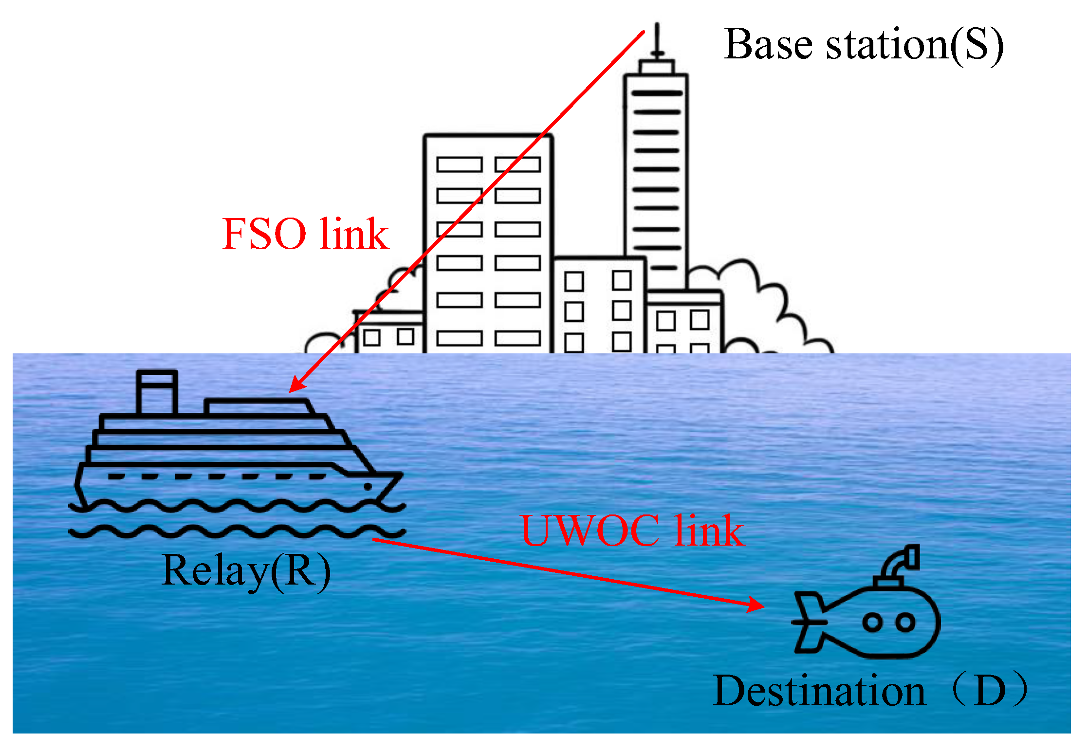
2. System and Channel Modeling

A mixed dual-hop FSO-UWOC transmission system experiencing hybrid fading on each propagation link is depicted in Figure 1. The system comprises three nodes: the transmitter node S, the relay node R, and the destination node D. The transmitter node S communicates with the underwater destination node D via a surface relay node R employing a DF relay protocol. The source signal at S is transmitted through the FSO link to node R, where it is decoded and reconstructed before being transmitted through the UWOC link to the destination node D. In the channel modeling process, both the FSO and UWOC links take into account the composite impacts of path loss, zero-boresight pointing errors, and turbulence. This is designed to offer a more comprehensive and accurate analysis for the mixed dual-hop system’s performance.
The received signal model at relay R can be expressed as y S R = P 1 h 1 s + n 1 , where P 1 is the transmitted power of the S-R link; h 1 denotes the channel fading under the influence of atmospheric turbulence fading h a , zero-boresight pointing error h p a and atmospheric path loss h l 1 , h 1 = h a h p a h l 1 ; s is the transmitted binary modulation symbol with average energy equal to 1; and n 1 is a Gaussian random variable with a mean of 0 and a variance of σ 1 2 .
When the DF relay protocol is used for the R-D link, the received signal at the destination node D in the R-D link is y R D = η P 2 h 2 s ^ + n 2 , where η is the photodetector conversion coefficient of the UWOC link, P 2 is the transmit power of the link, channel fading h 2 = h f h p h l 2 is affected by a combination of underwater turbulence fading h f , zero-boresight pointing error h p o and path loss h l 2 , s ^ represents the corresponding binary modulation and decoded reconstructed signal at node R, and n 2 is a Gaussian random variable with a mean of 0 and a variance of σ 2 2 .

2.1. Derivation of the PDF and CDF of Instantaneous SNR PDF and CDF for S-R Ink

The S-R link is modeled as an FSO hybrid-fading channel, which incorporates three key components: atmospheric path loss h l 1 , GG atmospheric turbulence effects h a , and zero-boresight pointing error h p a . As established in prior studies [15,26], atmospheric path loss h l 1 is accurately described by the single-exponential Beer–Lambert law: h l 1 = e σ Z . Here, Z denotes the S-R link transmission distance, and σ represents the atmospheric attenuation coefficient, which is dependent on environmental factors such as visibility. For fixed values of Z and σ , h l 1 remains a deterministic constant.
The PDF of the turbulence fading random variable following the GG distribution is given as [15,26]:
f h a = 2 α β α + β 2 Γ α Γ β h a α + β 2 1 K α β 2 α β h a
in the above equation, Γ represents the Gamma function, while K α β denotes the modified Bessel function of the second kind with an order of α β , where α > 0 , β > 0 are correlation coefficients associated with the Rytov variance σ R 2 . In the case of a plane wave, the corresponding formula is provided in [26]:
α = exp 0.49 σ R 2 1 + 1.11 σ R 12 / 5 7 / 6 1 1
β = exp 0.51 σ R 2 1 + 0.69 σ R 12 / 5 5 / 6 1 1
The zero-boresight pointing error random variable h p a is used to describe the displacement of the laser source from the vertical distance Z . Due to factors such as random platform jitter, the originally aligned transmitter and receiver experience random beam wandering R , which causes signal attenuation at the receiver. Its mathematical description can be approximately expressed as [27]:
f h p a h p a = ξ 1 2 A 0 ξ 1 2 h p a ξ 1 2 1 0 h p a A 0
where A 0 = e r f v 2 represents the power ratio of the laser beam received by the receiver at the detection center R = 0 , v = π r a / 2 w z denotes the ratio of the receiver aperture r a to the beam width w z , ξ 1 2 = w z e q 2 / 4 σ s 2 is the ratio of the equivalent beam radius w z e q to the standard deviation σ s of the pointing error displacement of the FSO link, and w z e q 2 = w z 2 π e r f v / 2 v e r f v 2 represents the equivalent beam width. The function e r f refers to the error function.
Therefore, the joint PDF of the hybrid channel fading h 1 = h l 1 h a h p a in the FSO link can be expressed as:
f h 1 h 1 = 0 f h 1 | h a h 1 | h a f h a h a d h a
where f h 1 | h a h 1 | h a represents the conditional PDF. Given the known values of h a and h l 1 , the PDF can be calculated based on the random variable function value criterion [28], as follows:
f h 1 | h a h 1 | h a = f h p a h p a h p a h 1     h p a = h 1 h a h l 1   = 1 h a h l 1 f h p a h 1 h a h l 1 = ξ 1 2 A 0 h a h l 1 ξ 1 2 h 1 ξ 1 2 1 h 1 h l 1 A 0 h a +
Substituting (6) and (1) into (4), the joint PDF of the hybrid-fading channel h 1 for the FSO link with zero-boresight pointing error can be written as:
f h 1 h 1 = h 1 h l 1 A 0 + f h 1 | h a h 1 | h a f h a h a d h a = 2 α β α + β 2 Γ α Γ β ξ 1 2 A 0 h l 1 ξ 1 2 h 1 ξ 1 2 1 h 1 h l 1 A 0 + h a α + β 2 ξ 1 2 1 K α β 2 α β h a d h a
Applying the identity K v 2 x = 1 2 G 0 , 2 2 , 0 x v / 2 , v / 2 [29] (Equation 8.4.23.1), along with [28] (Equations 2.24.2.3 and 8.2.2.15), Equation (7) can be further simplified as follows:
f h 1 h 1 = ξ 1 2 Γ α Γ β h 1 G 1 , 3 3 , 0 α β h 1 A 0 h l 1 1 + ξ 1 2 ξ 1 2 , α , β
The symbol G p , q m , n ( ) represents the Meijer-G function [30] (Equation 9.301).
Based on the definition of the moment-generating function for a random variable and referring to [30] (Equation 7.811.4), the n-th order raw moment is derived as:
E h 1 n = ξ 1 2 Γ α Γ β Γ ξ 1 2 + n Γ α + n Γ β + n Γ 1 + ξ 1 2 + n α β A 0 h l 1 n
(1)
The HD [31], i.e., coherent detection, combines a weak optical signal with a strong local oscillator signal at a photodetector. Based on the formulae in [31], in the case of the HD scheme, the instantaneous received SNR for the S-R link is denoted as γ 1 = P 1 h 1 / σ 1 2 , the average electronic received SNR is μ heterodyne = P 1 E h 1 σ 1 2 = P 1 A 0 ξ 1 2 h l 1 1 + ξ 1 2 σ 1 2 . Let η 1 = ξ 1 2 1 + ξ 1 2 , then h 1 = A 0 h l 1 η 1 γ 1 μ heterodyne , and the PDF of the instantaneous SNR γ is given by:
f γ 1 γ = f h 1 h 1 γ     h 1 = A 0 h l 1 η 1 γ μ heterodyne   = ξ 1 2 Γ α Γ β γ G 1 , 3 3 , 0 η 1 α β γ μ heterodyne 1 + ξ 1 2 ξ 1 2 , α , β
(2)
In the case of the IM/DD scheme [31], the instantaneous received SNR for the S-R link is denoted as γ 1 = P 1 h 1 2 / σ 1 2 , and the average electronic received SNR is μ I M / D D = P 1 E 2 h 1 σ 1 2 = P 1 A 0 2 ξ 1 4 h l 1 2 1 + ξ 1 2 2 σ 1 2 . Let η 1 = ξ 1 2 1 + ξ 1 2 , then h 1 2 = A 0 2 h l 1 2 η 1 2 γ 1 μ I M / D D , and the PDF of the instantaneous SNR γ is given by:
f γ 1 γ = f h 1 h 1 γ     h 1 = A 0 h l 1 η 1 γ μ I M / D D   = ξ 1 2 2 Γ α Γ β γ G 1 , 3 3 , 0 η 1 α β γ μ I M / D D 1 + ξ 1 2 ξ 1 2 , α , β
Combining the conclusions from (1) and (2), the following unified expression is obtained:
f γ 1 γ = ξ 1 2 r Γ α Γ β γ G 1 , 3 3 , 0 η 1 α β γ μ r 1 r 1 + ξ 1 2 ξ 1 2 , α , β
In the above expression, r is a constant related to the detection type, where r = 1 represents HD and r = 2 represents IM/DD; μ 1 = μ heterodyne , μ 2 = μ IM / DD .
Substituting Equation (12) into the CDF definition of γ 1 , F γ 1 γ = 0 γ f γ 1 x d x .
F γ 1 γ = 0 γ f γ 1 x d x = ξ 1 2 r Γ α Γ β 0 γ x 1 G 1 , 3 3 , 0 η 1 α β μ r 1 r x 1 r ξ 1 2 + 1 ξ 1 2 , α , β d x
By expanding the Meijer-G function in Equation (13) as per the definition in [30] (Equation 9.301), and using the properties of the Gamma function s Γ ( s ) = Γ ( s + 1 ) , we can obtain the closed-form expression for the CDF of the instantaneous SNR γ 1 under the hybrid-fading channel h 1 with path loss, zero-boresight pointing error, and atmospheric turbulence, as follows:
F γ 1 γ = ξ 1 2 Γ α Γ β G 2 , 4 3 , 1 η 1 α β γ μ r 1 r 1 , ξ 1 2 + 1 ξ 1 2 , α , β , 0

2.2. Derivation of the PDF and CDF of Instantaneous SNR PDF and CDF for the R-D Link

The R-D link (i.e., the UWOC link) also experiences hybrid channel fading due to path loss h l 2 caused by seawater absorption and scattering effects, oceanic turbulence h f , and zero-boresight pointing errors h p o .
The PDF of oceanic turbulence fading under the GGD model is given as follows [16]:
f h f h f = c h f a c 1 b a c exp h f b c Γ a , h f > 0
where b is a scale factor; a and c are shape parameters. Defining the scintillation index σ I 2 for turbulence as the normalized variance of the received light intensity fluctuations [21], and, furthermore, with the constraint of expectation E [ h f ] = 1 , the relationships among the three parameters a , b , c in GGD expression above and the scintillation index σ I 2 can be calculated by:
σ I 2 = Γ a Γ a + 2 / c Γ 2 a + 1 / c 1
b = Γ a Γ a + 1 / c
Clearly, by using Equations (16) and (17), we can determine the three parameters of the GGD model by predefining the scintillation index σ I 2 that characterizes the turbulence intensity and the shape parameter c in subsequent simulations.
Assume that the hybrid channel fading coefficient of the R-D link is h 2 = h f h p h l 2 , where h l 2 represents the UWOC link path loss. According to the research in [19], the path loss considering the absorption and scattering effects of seawater as well as geometric losses in the UWOC link can be accurately expressed by the Elamassie closed-form path-loss formula, i.e., h l 2 = D R θ d 2 e c 0 d D R θ d T . This is a function of the receiver aperture diameter D R , beam divergence angle θ , link transmission distance d , and extinction coefficient c 0 . Clearly, once variables such as D R , θ , and c 0 are fixed, h l 2 is a variable related to the transmission distance d between the transmitter and receiver nodes, which can be used to describe the path loss in the UWOC system.
From the proof process of Equation (6), it can be concluded that the conditional PDF of h 2 is given by:
f h 2 | h f h 2 | h f = f h p o h p o h p o h 2     h p = h 2 h f h l 2   = 1 h f h l 2 f h p o h 2 h f h l 2 = ξ 2 2 A 0 h f h l 2 ξ 2 2 h 2 ξ 2 2 1 h 2 A 0 h l 2 h f +
where ξ 2 2 represents the ratio of the equivalent beam waist radius to the standard deviation of the pointing error displacement in the UWOC link. From the proof of Equation (7), the PDF of the composite fading channel h 2 for the UWOC link can be expressed as:
f h 2 h 2 = h 2 A 0 h l 2 + f h 2 | h f h 2 | h f f h f h f d h f = c ξ 2 2 h 2 ξ 2 2 1 b a c A 0 h l 2 ξ 2 2 Γ a h 2 A 0 h l 2 + h f a c 1 ξ 2 2 exp h f b c d h f
Using Equation e x = G 0 , 1 1 , 0 x 0 [29] (Equation 8.4.3.1), and applying [29] (Equations 2.24.2.3, 8.2.2.15), Equation (19) can be further rewritten as:
f h 2 h 2 = ξ 2 2 h 2 Γ a G c , 1 + c 1 + c , 0 h 2 b A 0 h l 2 c [   ] ; 1 + ξ 2 2 c , , ξ 2 2 + c 1 c c 1 , c + ξ 2 2 c ξ 2 2 c , 1 + ξ 2 2 c , , ξ 2 2 + c 1 c c 1 , a ; [   ] = ξ 2 2 h 2 Γ a G 1 , 2 2 , 0 h 2 b A 0 h l 2 c c + ξ 2 2 c ξ 2 2 c , a
where the value of c is taken as an integer (it can be rounded to the nearest integer if non-integer). The second equality in the equation arises from the equivalence simplification of the G-function, as presented in [29] (Equation 8.2.2.9).
Based on the derived PDF of the hybrid fading channel coefficient h 2 , we now proceed to derive the PDF of the instantaneous received SNR γ 2 for the UWOC link.
(1)
Similarly, in HD, the instantaneous received SNR of the UWOC link is γ 2 = η P 2 h 2 / σ 2 2 , and the average electronic SNR is ρ heterodyne = η P 2 / σ 2 2 . Clearly, h 2 = γ 2 / ρ heterodyne , so the PDF of the instantaneous received SNR γ 2 is given by:
f γ 2 γ = f h 2 h 2 γ     h 2 = γ ρ heterodyne   = ξ 2 2 Γ a γ G 1 , 2 2 , 0 1 b A 0 c γ h l 2 ρ heterodyne c c + ξ 2 2 c ξ 2 2 c , a
(2)
In IM/DD, the instantaneous received SNR of the UWOC link is γ 2 = η 2 P 2 h 2 2 / σ 2 2 , and the average electronic SNR is ρ I M / D D = η 2 P 2 / σ 2 2 . Therefore, h 2 = γ 2 / ρ I M / D D , and based on this, the PDF of the instantaneous received SNR γ 2 can be derived as:
f γ 2 γ = f h 2 h 2 γ     h 2 = γ ρ I M / D D   = ξ 2 2 2 Γ a γ G 1 , 2 2 , 0 1 b A 0 c γ h l 2 2 ρ I M / D D c 2 c + ξ 2 2 c ξ 2 2 c , a
By combining the derivations from (1) and (2) above, the unified expression for the PDF of γ 2 can be obtained as:
f γ 2 γ = ξ 2 2 r Γ a γ G 1 , 2 2 , 0 1 b A 0 c γ ρ r c r c + ξ 2 2 c ξ 2 2 c , a
where r = 1 for HD and r = 2 for IM/DD; ρ 1 = h l 2 ρ heterodyne and ρ 2 = h l 2 2 ρ I M / D D .
Substituting Equation (23) into the CDF definition of γ 2 (given by F γ 2 γ = 0 γ f γ 2 x d x ) yields:
F γ 2 γ = ξ 2 2 r Γ a 0 γ x 1 G 1 , 2 2 , 0 1 b A 0 c ρ r c r x c r c + ξ 2 2 c ξ 2 2 c , a d x
Equation (24) can be derived and simplified using a process similar to that of Equation (14), leading to the following formulation:
F γ 2 γ = ξ 2 2 c Γ a G 2 , 3 2 , 1 1 b A 0 c γ ρ r c r 1 , ξ 2 2 c + 1 ξ 2 2 c , a , 0

3. Statistical Characteristics for End-to-End Instantaneous SNR

For the FSO-UWOC mixed dual-hop transmission system employing the DF relay scheme, the signal transmitted from the source node S is decoded and re-encoded into a new transmission signal at the relay node R. As a result, the FSO link and the UWOC link are statistically independent. Degradation in the performance of either link can lead to failure of the entire dual-hop system. Consequently, the end-to-end equivalent instantaneous SNR at the destination node D is determined by the minimum instantaneous SNR of the two hops [32]. Specifically, it can be expressed as:
γ D F = min γ 1 , γ 2

3.1. Derivation of the CDF for End-to-End Instantaneous SNR

For the DF relay protocol, the CDF of γ D F can be expressed as:
F γ D F γ = Pr min γ 1 , γ 2 < γ = 1 Pr min γ 1 , γ 2 γ = 1 Pr γ 1 γ , γ 2 γ = 1 Pr γ 1 γ Pr γ 2 γ = 1 1 F γ 1 γ 1 F γ 2 γ = F γ 1 γ + F γ 2 γ F γ 1 γ F γ 2 γ
By substituting Equations (14) and (25) into Equation (27), the closed-form expression for the CDF of γ D F can be obtained.

3.2. Derivation of the PDF for End-to-End Instantaneous SNR

Performing the first-order derivative operation with respect to the variable in Equation (27), the PDF of the end-to-end SNR for the FSO-UWOC mixed dual-hop link can be obtained as:
f γ D F γ = f γ 1 γ + f γ 2 γ f γ 1 γ F γ 2 γ F γ 1 γ f γ 2 γ
By substituting Equations (12), (14), (23), and (25) into Equation (28), the explicit closed-form expression for the PDF of γ D F can be obtained.

4. System Performance Analysis

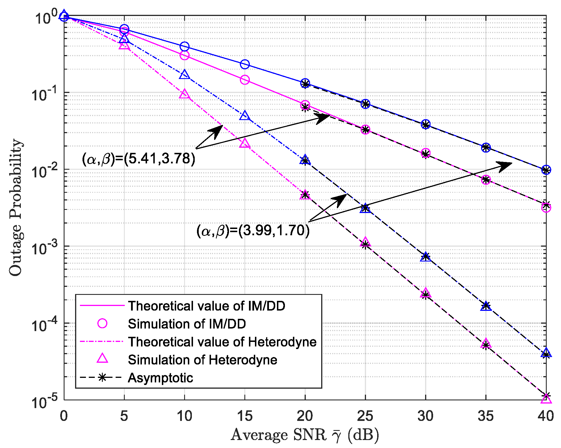
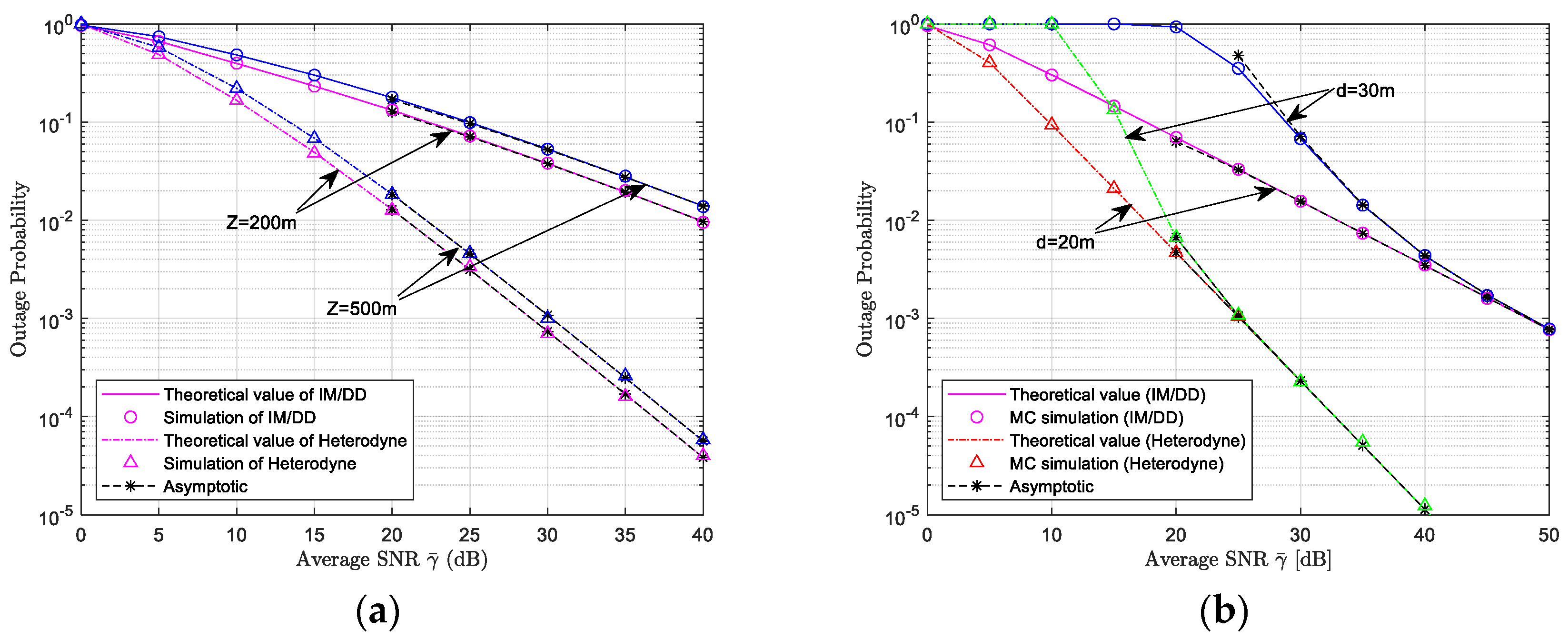
4.1. Outage Probability and Its Asymptotic Behavior

When the end-to-end SNR γ falls below a given threshold γ t h , the system transmission is interrupted and the probability of this event is calculated as the OP of the system [33]. Clearly, the OP of the FSO-UWOC mixed dual-hop transmission system can be described as:
P o u t = F γ D F γ t h
For the sake of analysis, let the average electronic SNRs of the FSO and UWOC links satisfy μ r = ρ r = γ ¯ , with γ μ r = γ ρ r 0 . Based on Equation (27), the asymptotic expression for the OP of the FSO-UWOC mixed dual-hop system is given by:
P o u t = F γ D F γ t h
P o u t F γ 1 γ t h + F γ 2 γ t h
where F γ 1 γ t h and F γ 2 γ t h represent the asymptotic values of F γ 1 γ t h and F γ 2 γ t h as γ ¯ . The asymptotic expression of F γ 1 γ t h , using [34] (Equation 07.34.06.0006.01), can be written as:
F γ 1 γ t h = Γ α ξ 1 2 Γ β ξ 1 2 Γ α Γ β η 1 α β ξ 1 2 γ μ r ξ 1 2 r + ξ 1 2 Γ α Γ β Γ β α ξ 1 2 α α η 1 α β α γ μ r α r + ξ 1 2 Γ α Γ β Γ α β ξ 1 2 β β η 1 α β β γ μ r β r .
Letting Δ 1 = Γ α ξ 1 2 Γ β ξ 1 2 Γ α Γ β η 1 α β ξ 1 2 , Δ 2 = ξ 1 2 Γ α Γ β Γ β α ξ 1 2 α α η 1 α β α , Δ 3 = ξ 1 2 Γ α Γ β Γ α β ξ 1 2 β β η 1 α β β .
Similarly, F γ 2 γ t h can be asymptotically expressed as:
F γ 2 γ t h = Γ a ξ 2 2 / c Γ a 1 b A 0 ξ 2 2 γ ρ r ξ 2 2 r + ξ 2 2 c Γ a 1 ξ 2 2 / c a a 1 b A 0 a   c γ ρ r a c r
Letting Δ 4 = Γ a ξ 2 2 / c Γ a b A 0 ξ 2 2 , Δ 5 = ξ 2 2 c Γ a 1 ξ 2 2 / c a a 1 b A 0 a c .
Therefore, when μ r = ρ r = γ ¯ , based on Equation (31), F γ D F γ t h can be asymptotically expressed as:
F γ D F γ t h Δ 1 γ t h ξ 1 2 r γ ¯ ξ 1 2 r + Δ 2 γ t h α r γ ¯ α r + Δ 3 γ t h β r γ ¯ β r + Δ 4 γ t h ξ 2 2 r γ ¯ ξ 2 2 r + Δ 5 γ t h a c r γ ¯ a c r
From the above equation, it can be seen that when the detection technique is fixed, i.e., the value of r is fixed, the performance of the OP is determined by the magnitude of the five parameters ξ 1 2 , ξ 2 2 , α , β , a c , which are the pointing errors of the two hops and the parameters characterizing atmospheric and oceanic turbulence. Specifically, the pointing error of the FSO link will dominate the system OP performance when ξ 1 2 takes the smallest value, while, when a c takes the minimum value, the turbulence in the UWOC link has the greatest impact on the OP.

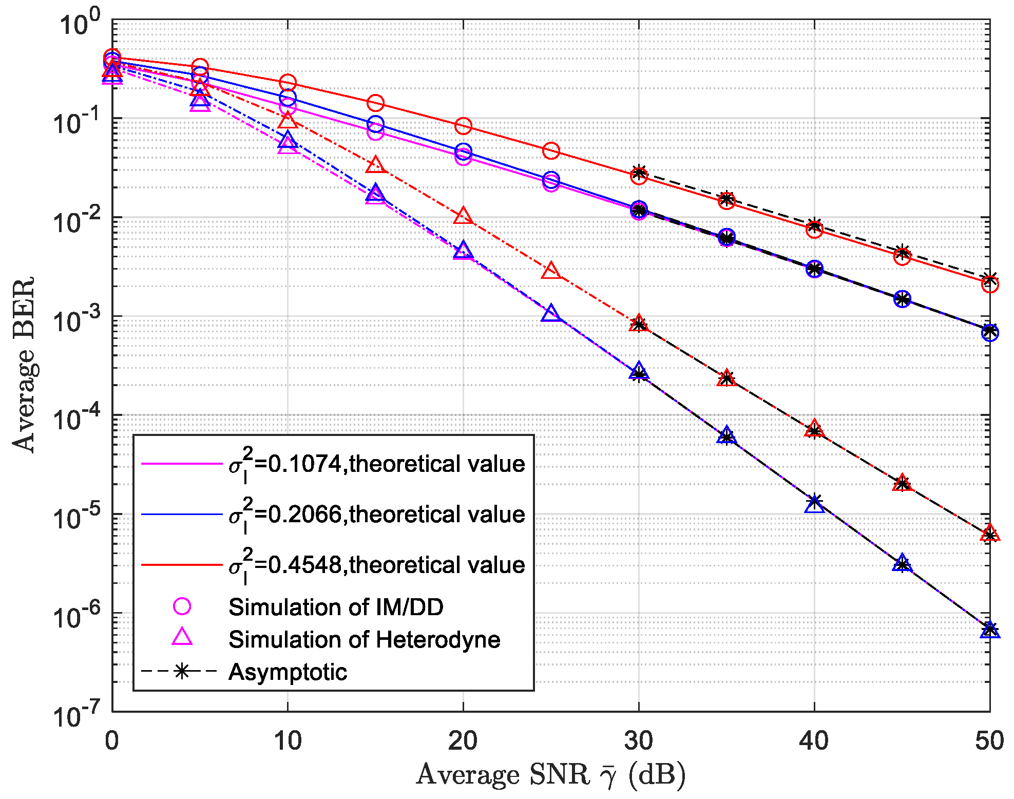
4.2. Average Bit Error Rate and Its Asymptotic Value

The average BER of a single link in a system under binary modulation can be represented as [35]:
P e = 0 P e ε γ f γ d γ = 0 P e ε γ d F γ
in the above expression, P e ε γ = Γ p , q γ 2 Γ p represents the conditional error rate given in the SNR γ , where Γ p , q γ denotes the upper incomplete Gamma function. Parameters p , q are modulation-related factors, with p = 1 / 2 , q = 1 / 2 for On–Off Keying (OOK) modulation.
Applying integration by parts to (35) and utilizing Γ a , z z = z a 1 e z [36] (Equation 6.5.25), the average BER simplifies to:
P e = q p 2 Γ p 0 F γ γ p 1 e q γ d γ
In the case of dual-hop DF relaying, it is straightforward to derive the end-to-end system BER as:
P e = P e , 1 ( 1 P e , 2 ) + ( 1 P e , 1 ) P e , 2 = P e , 1 + P e , 2 2 P e , 1 P e , 2
where P e , 1 represents the average BER of the S-R link, and P e , 2 represents the average BER of the R-D link.
And, when μ r = ρ r = γ ¯ , P e can be asymptotically expressed as:
P e P e , 1 + P e , 2
In this expression, P e , 1 and P e , 2 denote the asymptotic values of P e , 1 and P e , 2 when γ ¯ .
Substituting Equations (14) and (25) into Equation (36), using the identity e q γ = G 0 , 1 1 , 0 q γ 0 [29] (Equation 8.4.3.1), and simplifying using [29] (Equations 8.4.3.1, 2.24.1.1, 8.2.2.9, and 8.2.2.8), the BER for the S-R link can be written as:
P e , 1 = ξ 1 2 r α + β 2 2 2 π r 1 Γ ( p ) Γ ( α ) Γ ( β ) G 3 , 2 r + 2 2 r + 1 , 2 η 1 α β r μ r q r 2 r 1 , 1 p ; ξ 1 2 + r r ξ 1 2 r , M 1 , M 2 ; 0
where M 1 = α r , , α + r 1 r , M 2 = β r , , β + r 1 r are simplified notations for vectors, with each vector containing r terms.
Similarly, the average BER of the R-D link can be formulated as:
P e , 2 = ξ 2 2 r a 3 2 c p 1 2 2 c 2 π c + r 2 2 Γ p Γ a G c + 2 , r + 2 r + 1 , c + 1 c c b A 0 r c ρ r q c r r 1 , M 3 ; ξ 2 2 / c + r r ξ 2 2 / c r , M 4 ; 0
where M 3 = 1 p c , , c p c , M 4 = a r , , a + r 1 r , each vector contains r terms.
By substituting Equations (39) and (40) into Equation (37), the specific closed-form expression for the end-to-end average P e can be obtained.
Similarly, when the average links with SNR, i.e., μ r = ρ r = γ ¯ , the system’s average BER also has an asymptotic value. Utilizing [34] (Equation 07.34.06.0006.01), the asymptotic representation of P e , 1 can be formulated as:
P e , 1 = Θ 1 γ ¯ ξ 1 2 r + Θ 2 γ ¯ α r + Θ 3 γ ¯ β r
where
Θ 1 = r α + β 2 ξ 1 2 1 η 1 α β ξ 1 2 Γ α ξ 1 2 r Γ α ξ 1 2 + r 1 r Γ β ξ 1 2 r Γ β ξ 1 2 + r 1 r Γ p + ξ 1 2 r 2 2 π r 1 Γ ( p ) Γ ( α ) Γ ( β ) q ξ 1 2 r .
Θ 2 = ξ 1 2 r α + β 2 α η 1 α β α Γ 1 r Γ r r Γ β α r Γ β α + r 1 r Γ p + α r 2 2 π r 1 Γ ( p ) Γ ( α ) Γ ( β ) ξ 1 2 α α q α r
Θ 3 = ξ 1 2 r α + β 2 β η 1 α β β Γ α β r Γ α β + r 1 r Γ 1 r Γ r r Γ p + β r 2 2 π r 1 Γ ( p ) Γ ( α ) Γ ( β ) ξ 1 2 β β q β r
Similarly, when μ r = ρ r = γ ¯ , the asymptotic representation of P e , 2 can be written as:
P e , 2 = Θ 4 γ ¯ ξ 2 2 r + Θ 5 γ ¯ a c r
where
Θ 4 = r a 1 2 ξ 2 2 c c p 1 2 + ξ 2 2 r Γ α ξ 2 2 / c r Γ α ξ 2 2 / c + r 1 r Γ 1 1 p c + ξ 2 2 c r Γ 1 c p c + ξ 2 2 c r 2 2 π c + r 2 2 Γ p Γ a b A 0 ξ 2 2 q ξ 2 2 r
Θ 5 = ξ 2 2 r 1 2 c p 1 2 + a c r Γ 1 r Γ r r Γ 1 1 p c + a r Γ 1 c p c + a r 2 2 π c + r 2 2 Γ p Γ a a ξ 2 2 a c b A 0 a c q a c r
Therefore, combining Equations (41) and (42), when μ r = ρ r = γ ¯ , P e can be asymptotically expressed as:
P e Θ 1 γ ¯ ξ 1 2 r + Θ 2 γ ¯ α r + Θ 3 γ ¯ β r + Θ 4 γ ¯ ξ 2 2 r + Θ 5 γ ¯ a c r
Similar to the OP, when the detection technique is fixed, the BER is also determined by the magnitude of pointing errors of the two hops and the parameters characterizing atmospheric and oceanic turbulence.

4.3. Average Channel Capacity

The average channel capacity is determined by the expectation of the instantaneous mutual information between the source and destination nodes [37]:
C = 1 2 E [ log 2 ( 1 + τ γ ) ] = 1 2 ln 2 0 ln 1 + τ γ f γ D F ( γ ) d γ
where γ represents the end-to-end SNR of the hybrid dual-hop system, and τ is a constant whose value is determined by the specific receiver detection method. When r = 2 , corresponding to the IM/DD scheme, the derivation in [38] shows that τ = e / 2 π , and the channel capacity calculated by the above formula is actually the lower bound of the system’s capacity. On the other hand, when τ = 1 , the analysis in [39] indicates that the formula corresponds to the exact value of the system’s channel capacity under HD, rather than the lower bound.
Substituting Equation (28) into Equation (44) and performing transformations and manipulations using [29] (Equations 8.4.6.5, 8.3.2.21), as well as [40] (Equation 2.1.4), the average channel capacity of the mixed dual-hop transmission system under the DF relaying protocol can be obtained as:
C = 1 2 ln 2 0 H 22 12 τ γ 1 , 1 , 1 , 1 1 , 1 , 0 , 1 f γ D F ( γ ) d γ = 1 2 ln 2 ξ 1 2 Γ α Γ β 0 γ 1 H 1 , 3 3 , 0 η 1 α β r μ r γ 1 + ξ 1 2 , r ξ 1 2 , r , α , r , β , r H 22 12 τ γ 1 , 1 , 1 , 1 1 , 1 , 0 , 1 d γ I C 1 + 1 2 ln 2 ξ 2 2 c Γ a 0 γ 1 H 1 , 2 2 , 0 1 b A 0 r γ ρ r ξ 2 2 c + 1 , r c ξ 2 2 c , r c , a , r c H 22 12 τ γ 1 , 1 , 1 , 1 1 , 1 , 0 , 1 d γ I C 2 1 2 ln 2 ξ 1 2 ξ 2 2 r c Γ a Γ α Γ β 0 γ 1 G 22 12 τ γ 1 , 1 1 , 0 G 1 , 3 3 , 0 η 1 α β γ μ r 1 r 1 + ξ 1 2 ξ 1 2 , α , β G 2 , 3 2 , 1 1 b A 0 c γ ρ r c r 1 , ξ 2 2 c + 1 ξ 2 2 c , a , 0 d γ I C 3 1 2 ln 2 ξ 1 2 ξ 2 2 r Γ a Γ α Γ β 0 γ 1 G 22 12 τ γ 1 , 1 1 , 0 G 2 , 4 3 , 1 η 1 α β γ μ r 1 r 1 , ξ 1 2 + 1 ξ 1 2 , α , β , 0 G 1 , 2 2 , 0 1 b A 0 c γ ρ r c r c + ξ 2 2 c ξ 2 2 c , a d γ I C 4 = I C 1 + I C 2 I C 3 I C 4 .
Applying ([41], Equation 2.8.4), I C 1 can be expressed as:
I C 1 = ξ 1 2 2 ln 2 Γ α Γ β H 3 , 5 5 , 1 η 1 α β r μ r τ 0 , 1 ; 1 , 1 , 1 + ξ 1 2 , r ξ 1 2 , r , α , r , β , r , 0 , 1 , 0 , 1
Similarly, I C 2 can be expressed as:
I C 2 = ξ 2 2 2 c ln 2 Γ a H 3 , 4 4 , 1 1 b A 0 r ρ r τ 0 , 1 ; 1 , 1 , ξ 2 2 c + 1 , r c ξ 2 2 c , r c , a , r c , 0 , 1 , 0 , 1
By using [30] (Equation 9.301), [34] (Equation 07.34.21.0009.01) and [41] (Equation 1.1), I C 3 can be expressed as:
I C 3 = ξ 1 2 ξ 2 2 2 r c ln 2 Γ a Γ α Γ β H 4 , 0 : 1 , 3 : 2 , 3 0 , 3 : 3 , 0 : 2 , 1 χ 1 1 + ξ 1 2 , 1 ς 1 ψ 1 ψ 1 η 1 α β 1 μ r τ 1 r , 1 b A 0 c 1 ρ r τ c r
where χ 1 = 0 , 1 r , c r , 1 , 1 r , c r , 1 , 1 r , c r ; 1 , 1 r , c r , ς 1 = ξ 1 2 , 1 , α , 1 , β , 1 , ψ 1 = 1 , 1 ; ξ 2 2 c + 1 , 1 , ψ 2 = ξ 2 2 c , 1 , a , 1 ; 0 , 1 .
Similarly, I C 4 can be expressed as:
I C 4 = ξ 1 2 ξ 2 2 2 r ln 2 Γ a Γ α Γ β H 4 , 0 : 2 , 4 : 1 , 2 0 , 3 : 3 , 1 : 2 , 0 χ 1 ς 2 ς 3 ξ 2 2 c + 1 , 1 ψ 3 η 1 α β 1 μ r τ 1 r , 1 b A 0 c 1 ρ r τ c r
where ς 2 = 1 , 1 ; 1 + ξ 1 2 , 1 , ς 3 = ξ 1 2 , 1 , α , 1 , β , 1 ; 0 , 1 , ψ 3 = ξ 2 2 c , 1 , a , 1 .
By substituting Equations (46)–(49) into Equation (45), the specific closed-form expression for the system’s end-to-end average channel capacity C can be obtained.

5. Simulation Results and Analysis

In this section, we verify the accuracy of the theoretical analysis and investigate the impact of key parameter selections on system performance via MC simulations. The underwater simulation environment is configured based on typical nearshore coastal water quality, with an extinction coefficient c 0 = 0.305   m 1 , as reported in [19]. It is further assumed that the average SNRs of the two hops are equal, i.e., μ r = ρ r = γ ¯ , and the threshold SNR is set as γ t h = 2   dB . Table 2 below summarizes the typical values of critical parameters required for system simulation.

5.1. Outage Probability Simulation Results and Analysis

Figure 2 illustrates the theoretical and MC simulation results for the system’s OP as a function of the average SNR in the mixed dual-hop FSO-UWOC relay communication system. The analysis encompasses weak and strong atmospheric turbulence scenarios, parameterized by Rytov variances σ R 2 = 0.6 and σ R 2 = 2 , which correspond to fading parameters of the GG distribution α , β = 5.41 , 3.78 and α , β = 3.99 , 1.70 . Setting the strong pointing error for the first hop FSO link ξ 1 = 1.14 ( σ s = 10   cm , r a = 20   cm , w z = 40   cm ), while the second hop UWOC link has a weak pointing error ξ 2 = 4.0 ( σ s = 10 cm , r a = 30   cm , w z = 20   cm ). The atmospheric link spans a transmission distance of Z = 200   m , while the underwater link extends over d = 20   m , and the oceanic turbulence scintillation index is set to σ I 2 = 0.1074 . Solid lines represent the theoretical values of IM/DD detection, dashed lines represent the theoretical values of HD detection, circles represent the simulated values of IM/DD detection, and triangles represent the simulated values of HD detection.
From the simulation results shown in Figure 2, it can be observed that, under fixed UWOC link parameters such as underwater transmission distance, oceanic turbulence intensity, and pointing error conditions, the system experiences a rapid deterioration in OP performance due to the increase in atmospheric turbulence strength in the FSO link, regardless of whether IM/DD or HD is employed. This indicates that atmospheric turbulence has a significant impact on the OP performance. As for the detection schemes, since HD is a coherent detection method, HD achieves a lower system OP value than the incoherent IM/DD for the same average SNR. Moreover, the theoretical calculation results of the system align well with the MC simulation results, and the asymptotic OP values at high SNR closely match the corresponding theoretical values, further confirming the correctness of the closed-form derivation for the theoretical and asymptotic values of the OP, as described above.
Figure 3 demonstrates the impact of two different pointing error conditions, ξ 1 = 1.14 and ξ 1 = 1.52 , on the system’s OP. According to the definition ξ 1 2 = w z e q 2 / 4 σ s 2 , smaller ξ 1 values correspond to stronger pointing errors. The simulation curves from Figure 3 indicate that, under the same atmospheric turbulence conditions, the smaller the value of pointing error ξ 1 (i.e., as pointing errors become more severe), the worse the performance of the OP is. When the atmospheric turbulence Rytov variance σ R 2 changes from 0.6 to 2, with ξ 1 = 1.52 , the corresponding OP curve shows a more pronounced difference compared to the curve corresponding to ξ 1 = 1.14 . This indicates that pointing errors exert a more dominant influence on the OP than atmospheric turbulence effects. The asymptotic curves at high SNR are in good agreement with the theoretical curves of OP, which also verifies the correctness of the theoretical derivation of the asymptotic expression. The solid line represents the theoretical value at ξ 1 = 1.14 , and the dotted line represents the theoretical value at ξ 1 = 1.52 .
Figure 4 demonstrates the impact of different link transmission distances on the OP of the FSO-UWOC system, with the atmospheric turbulence Rytov variance set to σ R 2 = 2 and the oceanic turbulence scintillation index σ I 2 = 0.1074 . In Figure 4a, pointing error parameters for the FSO and UWOC links are configured as ξ 1 = 1.14 and ξ 2 = 4.0 , respectively. The plotted curves depict the theoretical and simulated system OP on the average SNR for atmospheric transmission distances of 200 m and 500 m, with the underwater distance fixed at 20 m. The simulation results from the figure clearly indicate that increasing the transmission distance of the FSO link will deteriorate the performance of the system OP. This degradation occurs because a longer FSO link increases the path loss, which, in turn, reduces the received SNR of the system.
Figure 4b depicts the OP as a function of the γ ¯ , with the atmospheric transmission distance fixed at 200 m and underwater distances set to 20 m and 30 m. Pointing error parameters for both hops are configured as ξ 1 = ξ 2 = 4.0 , representing weak pointing error conditions. Simulation results indicate that increasing the transmission distance of the UWOC link causes the deterioration of the OP performance, which is mainly reflected at low system average SNR. As γ ¯ increases, the impact of extended UWOC distance on end-to-end OP diminishes, approaching zero in the high-SNR limit. The reason for this behavior can be traced to the asymptotic formula of the OP given by Equation (34). It is clear that the asymptotic line is determined by five system fading parameters— α , β , a c , ξ 1 2 , ξ 2 2 —which characterize the atmospheric and oceanic turbulence, as well as the pointing errors of the two hops. In the simulation, the pointing errors of the dual hops were set at the same value, ξ 1 = ξ 2 = 4.0 , resulting in ξ 1 2 and ξ 2 2 being much larger than the other three parameters (with α , β = 3.99 , 1.70 , a c = 3.60 ). Consequently, in the high-SNR region, the asymptotic OP is dominated by the atmospheric turbulence parameter β —specific to the FSO link—and becomes independent of UWOC link parameters, including transmission distance. The close alignment between theoretical and asymptotic curves across different detection schemes in the high- γ ¯ regime further validates the accuracy of the derived closed-form OP expressions and the asymptotic approximations.

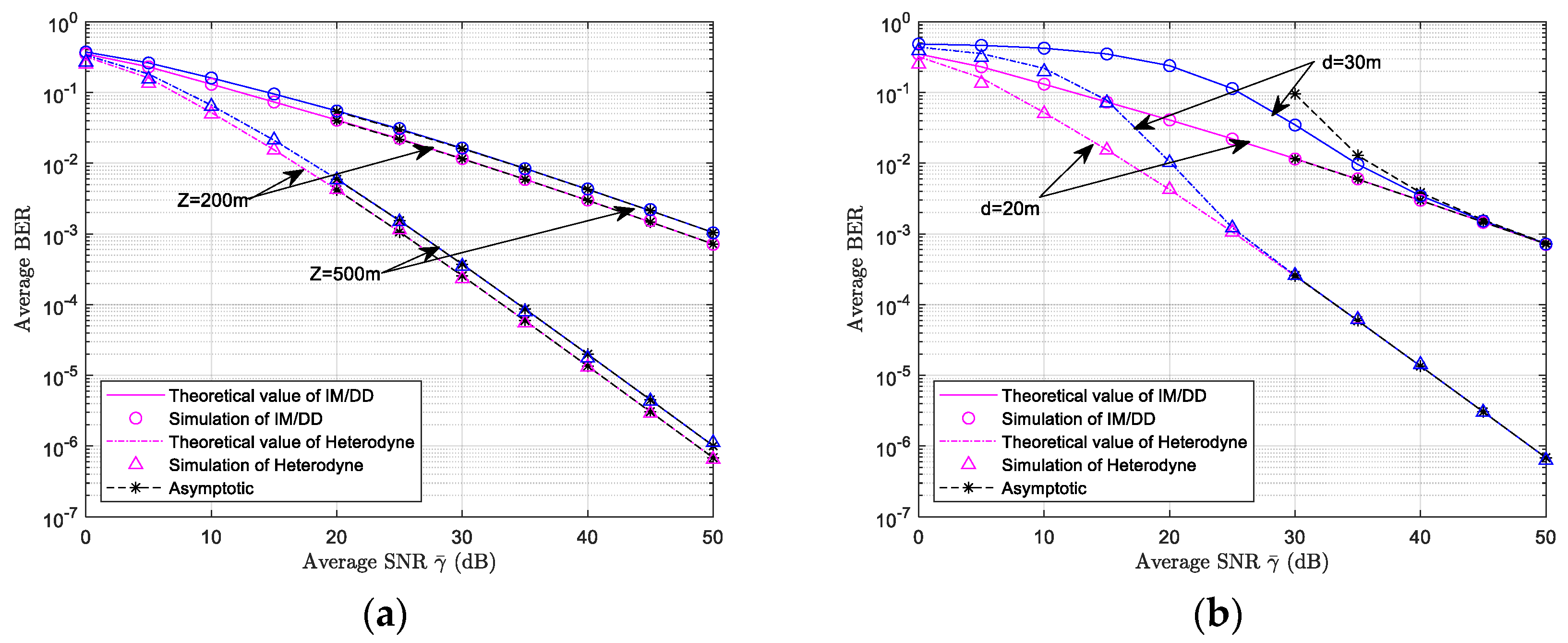
5.2. Average BER Simulation Results and Analysis

Figure 5 illustrates the curves of the average BER versus average SNR for the hybrid dual-hop FSO-UWOC system under conditions of weak atmospheric turbulence Rytov variance σ R 2 = 0.6 , strong pointing error in the first hop ξ 1 = 1.14 , and weak pointing error in the second hop ξ 2 = 4.00 . As depicted in Figure 5, the atmospheric transmission distance is fixed at Z = 200   m , while the underwater transmission distance is set to d = 20   m . Additionally, three distinct underwater turbulence scintillation index parameters are established as σ I 2 = 0 . 1074 / 0 . 2066 / 0 . 4548 . From the simulation results presented in Figure 5, it can be observed that, with the parameters of the FSO link (such as atmospheric turbulence, atmospheric transmission distance, and pointing error) fixed, the BER performance significantly degrades as the intensity of underwater turbulence increases, regardless of whether the system employs IM/DD or HD. This observation underscores the severe impact of oceanic turbulence intensity on the average BER performance. However, when the scintillation index, which characterizes the intensity of oceanic turbulence, begins to increase, the deterioration in system performance is not immediately apparent; for instance, at σ I 2 = 0 . 1074 and 0 . 2066 , the two performance curves almost overlap, while at σ I 2 = 0.4548 , a significant disparity in performance becomes evident. To further analyze the reasons, the asymptotic formula for the average BER, as given by Equation (43), reveals that the asymptotic average BER is influenced by five system fading parameters that characterize atmospheric and oceanic turbulence, as well as the pointing errors of the two hops. Solid lines represent the theoretical values of IM/DD detection, dashed lines represent the theoretical values of HD detection, circles represent the simulated values of IM/DD detection, and triangles represent the simulated values of HD detection.
When the oceanic turbulence scintillation index is set to 0.1074 and 0.2066 (corresponding to ac = 3.60 and 2.02), and other parameters are configured as α , β = 5.41 , 3.78 , ξ 1 = 1.14 , ξ 2 = 4.00 . It is evident that in high-SNR regions, the asymptotic value of the average BER is primarily determined by the pointing error of the FSO link, ξ 1 = 1.14 . This implies that, under these conditions, the average BER performance is largely independent of the intensity of oceanic turbulence. Conversely, as the oceanic turbulence intensity increases to σ I 2 = 0 . 4548 , the associated parameter a c = 1.01 becomes smaller than the other four parameters α , β , ξ 1 2 , ξ 2 2 , leading to the asymptotic value of this curve being dominated by the oceanic turbulence coefficient. Clearly, the BER curve corresponding to the oceanic turbulence σ I 2 = 0 . 4548 is significantly worse when compared to those for σ I 2 = 0 . 1074 / 0 . 2066 . Additionally, the simulation results reveal a high degree of agreement between the theoretical calculations and MC simulations. This consistency further validates the accuracy of the derived closed-form expressions for the BER and its asymptotic value.
Figure 4 and Figure 6 demonstrate the impact of varying link transmission distances on the average BER of the FSO-UWOC system. The analysis is conducted under strong atmospheric turbulence (Rytov variance σ R 2 = 2 ) and moderate marine turbulence conditions (scintillation index σ I 2 = 0.1074 ). Pointing error parameters for the two hops are configured as ξ 1 = 1.14 and ξ 2 = 4.00 , respectively. Figure 6a depicts theoretical and MC simulation results for the average BER as a function of the average SNR. The atmospheric transmission distance is set to two different values, 200 and 500 m, while the underwater transmission distance is fixed at 20 m. Since the reduction in the transmission distance of the FSO link can lead to a reduction in the loss of this link path, it is not difficult to see from the simulation results in the figure that, under the same conditions of the system parameter settings, the reduction in the transmission distance of the FSO link can effectively improve the average BER performance of the whole system.
Figure 6b shows the average BER curves as a function of the average SNR, with the atmospheric transmission distance fixed at 200 m and the underwater transmission distance varied at 20 and 30 m. The simulation results mirror the OP trends observed in Figure 4b: in the low-SNR regime, the UWOC link’s transmission distance significantly degrades the average BER, while its influence diminishes and becomes asymptotically negligible as the average SNR increases.
This behavior can be analyzed using the asymptotic BER formula derived in Equation (43), which identifies the dominant fading parameters governing system performance. Under the current simulation configuration—GG turbulence coefficients α , β = 3.99 , 1.70 , oceanic turbulence parameter a c = 3.60 , and pointing error parameters ξ 1 2 = 1.30 and ξ 2 = 4.00 —the pointing error of the FSO link ξ 1 2 emerges as the smallest among all system parameters. In high-SNR regions, this makes the asymptotic average BER exclusively dependent on ξ 1 2 , rendering UWOC link parameters (including transmission distance) irrelevant to performance. The close overlap between theoretical closed-form BER predictions and asymptotic values across different detection schemes in the high-SNR domain further validates the accuracy of the derived expressions.

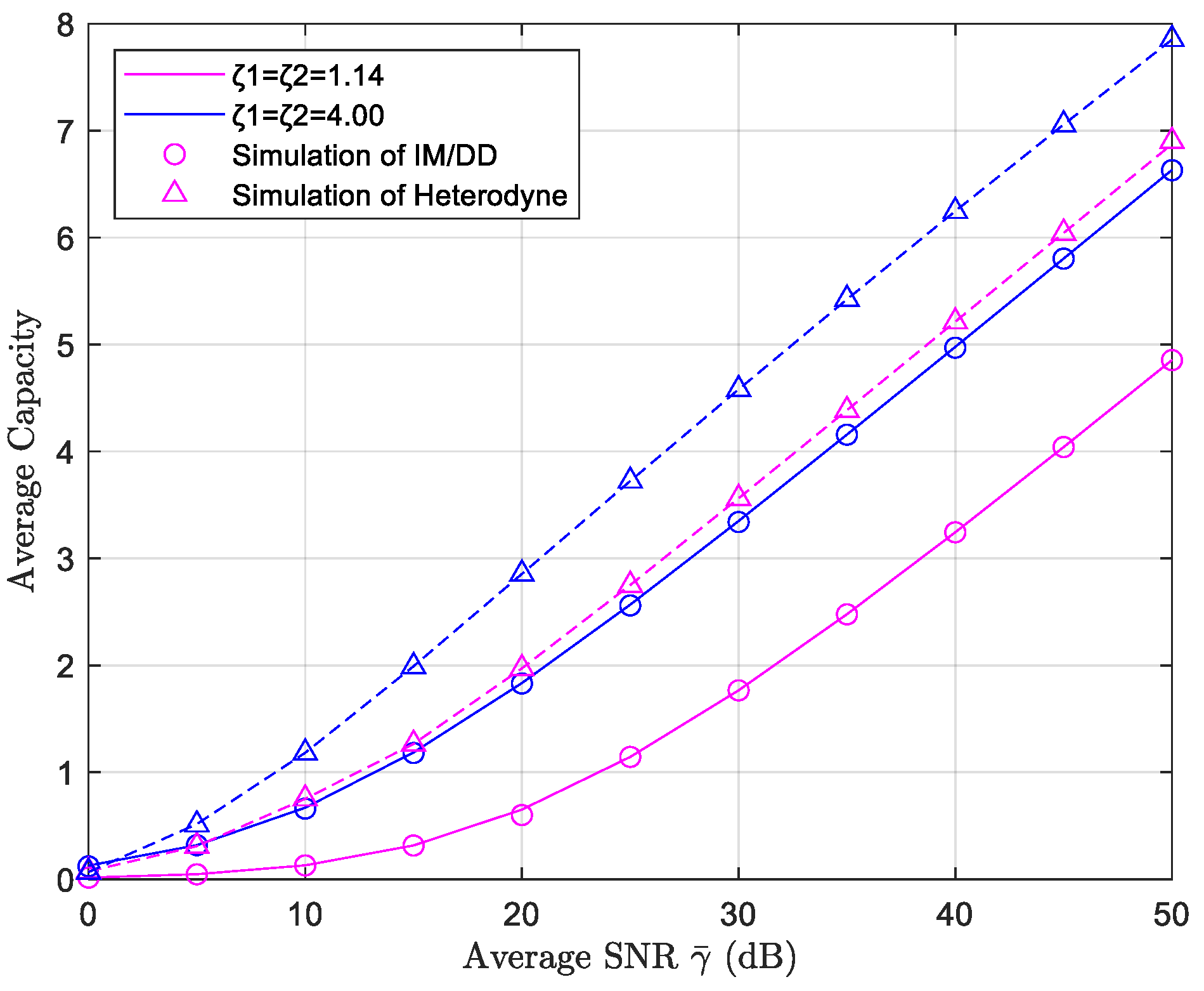
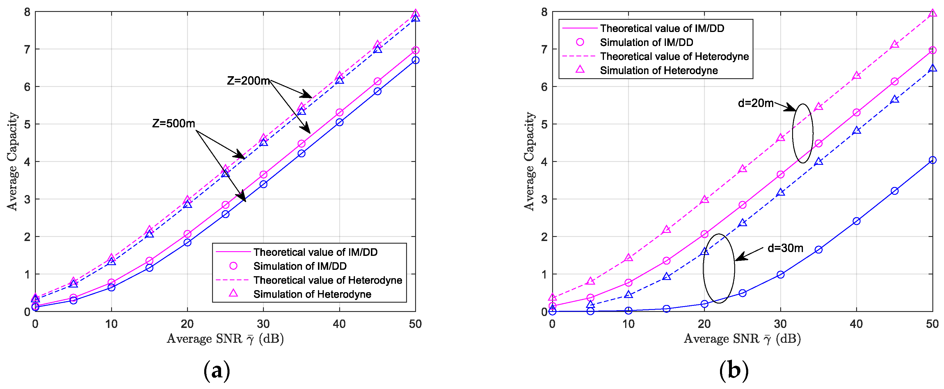
5.3. Average Channel Capacity Simulation Results and Analysis

Figure 7 presents the theoretical and MC simulation curves of the average channel capacity for a dual-hop FSO-UWOC system under an atmospheric turbulence Rytov variance σ R 2 = 0.6 and a fixed marine turbulence scintillation index σ I 2 = 0.1074 . Pointing error parameters for both hops are set to the same value ( ξ 1 = ξ 2 = 1.14 or ξ 1 = ξ 2 = 4.00 ), depicted by pink/blue curves, respectively. The atmospheric and underwater transmission distances are fixed at Z = 200   m , and d = 20   m , respectively. Simulation results demonstrate strong alignment between theoretical average channel capacity values and MC simulations, validating the accuracy of the derived closed-form expressions. The expressions formulated in Section 4.3 indicate that channel capacity depends on the detection method, pointing errors of the two hops, atmospheric turbulence coefficients, and oceanic turbulence parameters. Therefore, under identical detection, turbulence, and distance conditions, dual-hop pointing errors become the primary factor influencing channel capacity: weaker pointing errors yield superior average channel capacity performance. Additionally, since HD is coherent detection, for the same average SNR, HD will yield a higher system average channel capacity value than non-coherent IM/DD detection.
Figure 8 illustrates the impact of varying link transmission distances on the average channel capacity of the FSO-UWOC system under weak atmospheric turbulence (Rytov variance σ R 2 = 0.6 ) and moderate oceanic turbulence (scintillation index σ I 2 = 0.1074 ). Both hops are configured with weak pointing errors ( ξ 1 = ξ 2 = 4.00 ). Figure 8a presents theoretical and simulation results for average channel capacity as a function of the average SNR γ ¯ , with atmospheric transmission distances set to 200 m and 500 m and the underwater distance fixed at 20 m. Simulation results show that increasing the FSO link’s transmission distance degrades average channel capacity under identical parameters. This degradation arises from increased atmospheric path loss in longer FSO links, which lowers the system’s average SNR. Notably, however, the impact of atmospheric transmission distance on channel capacity remains relatively moderate compared to other factors like turbulence intensity or pointing error severity.
Figure 8b displays the average channel capacity curves as a function of the average SNR, with the atmospheric transmission distance fixed at 200 m and underwater distances set to 20 m and 30 m, respectively. The results show that increasing the underwater transmission distance induces significant degradation in average channel capacity, particularly under the IM/DD scheme. Specifically, the system exhibits notably higher channel capacity at 20 m compared to 30 m across all tested SNR values.

6. Conclusions

This study explores the system performance of a mixed dual-hop FSO-UWOC system with the DF relay protocol for two representative detection techniques (HD and IM/DD). Using the higher transcendental Meijer-G function and the bivariate Fox-H function, theoretical closed-form expressions for average OP, average BER, and average channel capacity are derived. Asymptotic expressions for average OP and BER under high average SNR conditions are also presented. Theoretical and simulation results reveal that atmospheric and oceanic turbulence intensity, pointing error, and transmission distances significantly influence the system performance. The asymptotic expressions further illustrate that OP and BER are mainly affected by the integrated impacts of various parameters characterizing the atmospheric turbulence intensity, oceanic turbulence intensity, and pointing errors in both FSO and UWOC links. Under the same parameter configurations and average SNR, coherent detection (i.e., HD scheme) outperforms non-coherent detection (IM/DD scheme) significantly, owing to its inherent advantages in signal extraction and noise suppression. Finally, the MC simulation results are almost consistent with those of the derived theoretical formulae, validating the accuracy of the proposed closed-form and asymptotic expressions for the average OP, BER, and average channel capacity of the mixed dual-hop FSO-UWOC systems. These findings offer profound insights into the operational mechanism of hybrid FSO-UWOC dual-hop systems.

Author Contributions

Conceptualization, M.J.; methodology, Y.L. (Yueheng Li) and Y.L. (Yong Lv); validation, Y.Z. and Y.L. (Yueheng Li); formal analysis, Y.L. (Yueheng Li); writing—original draft preparation, Y.Z.; writing—review and editing, Y.L. (Yueheng Li); supervision, Y.L. (Yong Lv). All authors have read and agreed to the published version of the manuscript.

Funding

This research was funded by the National Natural Science Foundation of China (No. U23B20144).

Data Availability Statement

The data supporting the findings of this study are presented within the article.

Conflicts of Interest

The authors declare no conflicts of interest.

References

  1. You, X.H.; Wang, C.-X.; Huang, J.; Gao, X.; Zhang, Z.; Wang, M.; Huang, Y.; Zhang, C.; Jiang, Y.; Wang, J.; et al. Towards 6G wireless communication networks: Vision, enabling technologies, and new paradigm shifts. Sci. China Inf. Sci. 2021, 64, 110301. [Google Scholar] [CrossRef]
  2. Ali, M.F.; Jayakody, D.N.; Li, Y. Recent trends in underwater visible light communication (UVLC) systems. IEEE Access 2022, 10, 22169–22225. [Google Scholar] [CrossRef]
  3. Mondal, A.; Hossain, A. Channel characterization and performance analysis of unmanned aerial Vehicle-Operated communication system with multihop radio Frequency–Free-Space optical link in dynamic environment. Int. J. Commun. Syst. 2020, 33, e4568. [Google Scholar] [CrossRef]
  4. Li, S.; Yang, Y.; Yang, L.; Bian, Y. On the Study of Multiuser Mixed Dual-Hop RF/THz Systems. IEEE Trans. Veh. Technol. 2023, 72, 9175–9188. [Google Scholar] [CrossRef]
  5. Wang, S.; Yang, L.; Li, X.; Guo, K.; Liu, H.; Song, H.; Jhaveri, R.H.; Quo, K. Performance Analysis of Satellite-Vehicle Networks with a Non-Terrestrial Vehicle. IEEE Trans. Intell. Veh. 2024, 9, 1691–1700. [Google Scholar] [CrossRef]
  6. Li, S.; Yang, L.; Costa, D.B.; Di Renzo, M.; Alouini, M.-S. On the Performance of RIS-assisted dual-hop mixed RF-UWOC systems. IEEE Trans. Cogn. Commun. Netw. 2021, 7, 340–353. [Google Scholar] [CrossRef]
  7. Yadav, S.; Vats, A.; Aggarwal, M.; Ahuja, S. Performance Analysis and Altitude Optimization of UAV-Enabled Dual-Hop Mixed RF-UWOC System. IEEE Trans. Veh. Technol. 2021, 70, 12651–12660. [Google Scholar] [CrossRef]
  8. Samir, A.; Elsayed, M.; El-Banna, A.A.A.; Ansari, I.S.; Rabie, K.; ElHalawany, B.M. Performance analysis of dual-hop hybrid RF-UOWC NOMA systems. Sensors 2022, 22, 4521. [Google Scholar] [CrossRef] [PubMed]
  9. Zhou, B.; Wang, P.; Cao, T.; Li, G.; Li, S.; Yang, P. Performance analysis of AUV-Carried RISs-Aided multihop UWOC convergent with RF MRC systems over WGG oceanic turbulence. Veh. Commun. 2024, 45, 100722. [Google Scholar] [CrossRef]
  10. Agarwal, A.; Singh, K. Energy-Efficient UOWC-RF systems with SLIPT. Trans. Emerg. Telecommun. Technol. 2024, 35, e4889. [Google Scholar] [CrossRef]
  11. Yang, L.; Zhu, Q.; Li, S.; Ansari, I.S.; Yu, S. On the performance of mixed FSO-UWOC dual-hop transmission systems. IEEE Wirel. Commun. Lett. 2021, 10, 2041–2045. [Google Scholar] [CrossRef]
  12. Naik, R.P.; Chung, W.Y. Performance evaluation of re-Configurable intelligent Surface-Assisted underwater and Free-Space wireless optical communication in the Skip-Zones. ICT Express 2024, 10, 320–329. [Google Scholar]
  13. Sharma, D.; Agrawal, R.; Joshi, D.; Rani, R.; Shariff, A.S.M.; Singh, H. Performance analysis of mixed FSO-UWOC dual-hop transmission system. In Proceedings of the 2024 IEEE International Conference on Computing, Power and Communication Technologies (IC2PCT), Greater Noida, India, 9–10 February 2024; pp. 658–662. [Google Scholar]
  14. Kumar, L.B.; Ramavath, P.N.; Krishnan, P. Performance analysis of Multi-Hop FSO convergent with UWOC system for security and tracking in navy applications. Opt. Quant. Electron. 2022, 54, 327. [Google Scholar] [CrossRef]
  15. Farid, A.A.; Hranilovic, S. Outage capacity optimization for Free-Space optical links with pointing errors. J. Light. Technol. 2007, 25, 1702–1710. [Google Scholar] [CrossRef]
  16. Oubei, H.M.; Zedini, E.; Elafandy, R.T.; Kammoun, A.; Abdallah, M.; Ng, T.K.; Hamdi, M.; Alouini, M.-S.; Ooi, B.S. Simple statistical channel model for weak Temperature-Induced turbulence in underwater wireless optical communication systems. Opt. Lett. 2017, 42, 2455–2458. [Google Scholar] [CrossRef]
  17. Jamali, M.V.; Mirani, A.; Parsay, A.; Abolhassani, B.; Nabavi, P.; Chizari, A.; Khorramshahi, P.; Abdollahramezani, S.; Salehi, J.A. Statistical studies of fading in underwater wireless optical channels in the presence of air bubble, temperature, and salinity random variations. IEEE Trans. Commun. 2018, 66, 4706–4723. [Google Scholar] [CrossRef]
  18. Zedini, E.; Oubei, H.M.; Kammoun, A.; Hamdi, M.; Ooi, B.S.; Alouini, M.-S. Unified statistical channel model for Turbulence-Induced fading in underwater wireless optical communication systems. IEEE Trans. Commun. 2019, 67, 2893–2907. [Google Scholar] [CrossRef]
  19. Elamassie, M.; Miramirkhani, F.; Uysal, M. Performance characterization of underwater visible light communication. IEEE Trans. Commun. 2019, 67, 543–552. [Google Scholar] [CrossRef]
  20. Deka, R.; Anees, S. On the performance of DF based triple hop RF–FSO–UWOC cooperative system. Opt. Quantum Electron. 2024, 56, 1155. [Google Scholar] [CrossRef]
  21. Le-Tran, M.; Kim, S. Performance analysis of Multi-Hop underwater wireless optical communication systems over Exponential-Generalized gamma turbulence channels. IEEE Trans. Veh. Technol. 2022, 71, 6214–6227. [Google Scholar] [CrossRef]
  22. Jamali, M.V.; Nabavi, P.; Saleihi, J.A. MIMO underwater visible light communications: Comprehensive channel study, performance analysis, and Multiple-Symbol detection. IEEE Trans. Veh. Technol. 2018, 67, 8223–8237. [Google Scholar] [CrossRef]
  23. Ye, N.; Miao, S.; Pan, J.; Xiang, Y.; Mumtaz, S. Dancing with Chains: Spaceborne Distributed Multi-User Detection Under Inter-Satellite Link Constraints. IEEE J. Sel. Top. Signal Process. 2025, 19, 430–446. [Google Scholar] [CrossRef]
  24. Zhuo, X.; Liu, M.; Wei, Y.; Yu, G.; Qu, F.; Sun, R. AUV-Aided Energy-Efficient Data Collection in Underwater Acoustic Sensor Networks. IEEE Internet Things J. 2020, 7, 10010–10022. [Google Scholar] [CrossRef]
  25. Jayakody, D.N.K.; Flanagan, M.F. A Soft Decode-Compress-Forward Relaying Scheme for Cooperative Wireless Networks. In Proceedings of the 2013 IEEE 24th International Symposium on Personal, Indoor and Mobile Radio Communications (PIMRC Workshops), London, UK, 8–11 September 2013; pp. 205–209. [Google Scholar]
  26. Wang, J.Y.; Ma, Y.; Lu, R.R.; Wang, J.-B.; Lin, M.; Cheng, J. Hovering UAV-Based FSO communications: Channel modelling, performance analysis, and parameter optimization. IEEE J. Sel. Areas Commun. 2021, 39, 2946–2959. [Google Scholar] [CrossRef]
  27. Lin, Z.; Xu, G.; Zhang, Q.; Song, Z. Average symbol error probability and channel capacity of the underwater wireless optical communication systems over oceanic turbulence with pointing error impairments. Opt. Express 2022, 30, 15327–15343. [Google Scholar] [CrossRef] [PubMed]
  28. Proakis, J.G. Digital Communications, 5th ed.; McGraw-Hill Companies: New York, NY, USA, 2007. [Google Scholar]
  29. Prudnikov, A.P.; Brychkov, Y.A.; Marichev, O.I. Integrals and Series: Volume 3: More Special Functions; Revista De Ciencias Farmaceuticas: Moscow, Russia, 1989. [Google Scholar]
  30. Gradshteyn, I.S.; Ryzhik, I.M. Table of Integrals, Series and Products, 7th ed.; Academic Press: Boston, MA, USA, 2007. [Google Scholar]
  31. Ansari, I.S.; Alouini, M.-S.; Yilmaz, F. A Unified Performance Analysis of Free-Space Optical Links Over Gamma-Gamma Turbulence Channels with Pointing Errors. 2013. Available online: http://hdl.handle.net/10754/305353 (accessed on 20 May 2024).
  32. Li, S.; Yang, L.; Costa, D.B.D.; Zhang, J.; Alouini, M.-S. Performance analysis of mixed RF-UWOC Dual-Hop transmission systems. IEEE Trans. Veh. Technol. 2020, 69, 14043–14048. [Google Scholar] [CrossRef]
  33. Simon, M.K.; Alouini, M.S. Digital Communications Over Fading Channels: A Unified Approach to Performance Analysis; Wiley-IEEE Press: New York, NY, USA, 2005. [Google Scholar]
  34. Wolfram. The Wolfram Functions Site. Available online: https://functions.wolfram.com (accessed on 10 April 2025).
  35. Ashrafzadeh, B.; Nasab, E.S.; Kamandar, M.; Uysal, M. A framework on the performance analysis of dual-hop mixed fso-rf cooperative systems. IEEE Trans. Commun. 2019, 67, 4939–4954. [Google Scholar] [CrossRef]
  36. Abramowitz, M.; Stegun, I.A. Handbook of Mathematical Functions with Formulas, Graphs, and Mathematical Tables; Dover Publications: Garden City, NK, USA, 1966. [Google Scholar]
  37. Zedini, E.; Soury, H.; Alouini, M.S. Dual-Hop FSO transmission systems over Gamma–Gamma turbulence with pointing errors. IEEE Trans. Wirel. Commun. 2017, 16, 784–796. [Google Scholar] [CrossRef]
  38. Lapidoth, A.; Moser, S.M.; Wigger, M.A. On the capacity of Free-Space optical intensity channels. IEEE Trans. Inf. Theory 2009, 55, 4449–4461. [Google Scholar] [CrossRef]
  39. Farhadi, G.; Beaulieu, N.C. On the ergodic capacity of Multi-Hop wireless relaying systems. IEEE Trans. Wirel. Commun. 2009, 8, 2286–2291. [Google Scholar] [CrossRef]
  40. Kilbas, A.A. H-Transforms; Chapman & Hall/CRC: Boca Raton, FL, USA, 2004. [Google Scholar]
  41. Mittal, P.K.; Gupta, K.C. An Integral Involving Generalized Function of Two Variables. Proc. Indian. Acad. Sci.-Sect. A 1972, 75, 117–123. [Google Scholar] [CrossRef]
Figure 1. FSO-UWOC mixed dual-hop transmission system.
Electronics 14 02227 g001
Figure 2. Outage probability under different detection schemes of a mixed FSO-UWOC system ( ξ 1 = 1.14 , ξ 2 = 4.00 ).
Electronics 14 02227 g002
Figure 3. Outage probability under different pointing errors for mixed FSO-UWOC system under IM/DD scheme ( ξ 1 = 1.14 , ξ 1 = 1.52 , ξ 2 = 4.0 ).
Electronics 14 02227 g003
Figure 4. Effect of different link transmission distances on the outage probability of FSO-UWOC systems: (a) changing the FSO link transmission distance Z ; (b) changing the UWOC link transmission distance d .
Electronics 14 02227 g004
Figure 5. Average BER of mixed FSO-UWOC system with different oceanic turbulence scintillation indices ( ξ 1 = 1.14 , ξ 2 = 4.00 ).
Electronics 14 02227 g005
Figure 6. Effect of different link transmission distances on the average BER of the FSO-UWOC system: (a) varying the FSO link transmission distance Z ; (b) varying the UWOC link transmission distance d .
Electronics 14 02227 g006
Figure 7. Average channel capacity of mixed FSO-UWOC system under different detection methods ( ξ 1 = 1.14 , ξ 2 = 4.00 ).
Electronics 14 02227 g007
Figure 8. Effect of different link transmission distances on the average channel capacity of the FSO-UWOC system: (a) changing the FSO link transmission distance Z ; (b) changing the UWOC link transmission distance d .
Electronics 14 02227 g008
Table 1. Dual-hop RF-UWOC/FSO-UWOC analysis: state of the art.
RefsYearAir Link StatisticsUWOC Link
Statistics
Pointing
Error
Path LossRelay TypeDetec. MethodDerived
Metrics
Asym.
Analysis
[6]2021RF/
Generalized K
EGGNoNoAF/
DF
HD,
IM/DD
OP, BER, capacityYes
[7]2021RF/NakagamiEGGNoRF/
Exponent
DFIM/DDOP, BERNo
[8]2022RF/RayleighEGGNoNoDFHD,
IM/DD
OP, capacityYes
[9]2024RF/Fisher-Snedecor FWeibull-GGDUWOCUWOC/
BL
DFIM/DDOP, BERNo
[10]2023RF/RayleighLognormal/GGNoUWOC/
Elamassie
DFIM/DDcapacityNo
[11]2021FSO/GGEGGDual linkNoAFHD,
IM/DD
OP, BER,
capacity
Yes
[12]2024FSO/GGLognormalFSONoDFHD,
IM/DD
OP, BERYes
[13]2024FSO/Fisher-Snedecor FEGGDual linkNoAFIM/DDOPNo
[14]2022FSO/GGLognormalDual linkDual/BLDFIM/DDOP, BERNo
Table 2. Key parameters used for FSO-UWOC system performance simulations [11,14,16,17,19,26,27].
CoefficientSymbolValue
Rytov variance σ R 2 0.6 / 2
Atmospheric attenuation coefficients σ 1 / 1000   m 1
Atmospheric transmission distance Z Z = 200 / 500   m
Full-width beam divergence θ 1 / e 6 °
correction factor T 0.13
Underwater transmission distance d d = 20 / 30   m
jitter deviation σ s 10 / 20   cm
Receiver radius r a 20 / 30   cm
Beam width w z 40 / 20   cm
Oceanic turbulence scintillation index σ I 2 0 . 1074 / 0 . 2066 / 0 . 4548
underwater extinction coefficients c 0 0.305   m 1
GGD shape parameters c 3
Disclaimer/Publisher’s Note: The statements, opinions and data contained in all publications are solely those of the individual author(s) and contributor(s) and not of MDPI and/or the editor(s). MDPI and/or the editor(s) disclaim responsibility for any injury to people or property resulting from any ideas, methods, instructions or products referred to in the content.

