1. Introduction
The Buck converter, which is widely employed in electric vehicles [
1,
2,
3], microgrids [
4], and energy storage systems [
5,
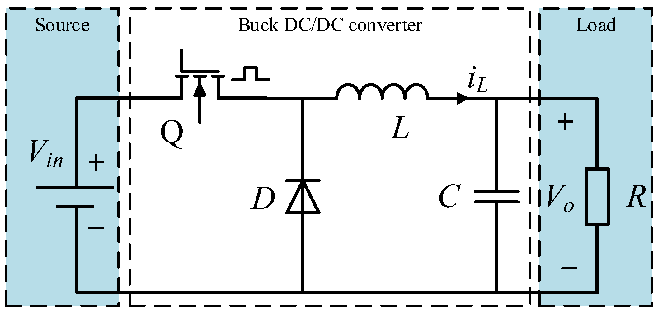
6], is a common type of DC/DC circuit. However, due to its inherent characteristics as a time-varying nonlinear system, the Buck converter is particularly sensitive to variations in internal parameters, load disturbances, and fluctuations in input voltage under real-world operating conditions. These factors frequently result in issues such as unstable output voltage and diminished control accuracy. As a result, numerous scholars have undertaken extensive research into innovative control strategies aimed at improving the output voltage control performance and enhancing the anti-interference capability of Buck converters.
For the Buck DC/DC converters, numerous researchers have proposed a series of control methods. Reference [
7] developed a self-PID control strategy for the DC/DC converter using an FPGA-based experimental platform. This approach enhanced the system’s response speed to some extent; however, it was associated with a high computational complexity issue. Reference [
8] presents the design of a sliding mode control (SMC) for a DC/DC converter, achieving integral sliding mode control through the implementation of a nonlinear control law. Reference [
9] proposes a voltage-ripple (VR)-based dynamic freewheeling (DF) control technique for a hybrid conduction mode (HCM) single-inductor dual-output (SIDO) Buck converter to address the key limitations of Pseudocontinuous Conduction Mode (PCCM) SIDO converters. Reference [
10] addresses the noise issue in DC/DC converters by employing Extended State Observer (ESO) cascading and Active Disturbance Rejection Control (ADRC). This approach not only mitigates the noise problem, but also enhances the stability of the system. For the parameter design in the DC/DC converter, reference [
11]. Six discrete iterative models with potential evolutionary capabilities were established based on the power characteristics of the Buck converter operating in Continuous Conduction Mode (CCM). Furthermore, the parameter dynamic behavior of PWM modulation under varying pulse widths was elucidated via bifurcation diagrams. This analysis was extended to derive the boundary equations for the closed-loop stability of the system, thereby providing theoretical guidance for ensuring stable system control. As an alternative control strategy to the PI controller, Active Disturbance Rejection Control (ADRC) demonstrates strong robustness and high control accuracy. This can effectively address the trade-off between “rapidity” and “overshoot” associated with the PI controller. ADRC has been widely implemented in practical applications [
12,
13,
14]. The Buck converter is a nonlinear time-varying system. In certain complex operating environments, the traditional integer PI control method exhibits low precision and a limited range. To compensate for the limitations of linear system control methods, active disturbance rejection can be applied to the Buck converter. However, LADRC is typically designed based on a simplified mathematical model. Consequently, when the input voltage or load undergoes rapid changes, the controller, limited by the model simplification, fails to estimate the system state and disturbances accurately and promptly, which in turn compromises the control performance. Additionally, the effectiveness of LADRC heavily relies on the appropriate tuning of parameters such as observer bandwidth and controller gain. Nevertheless, in practical applications, owing to the complex dynamic behavior of Buck-type DC/DC converters and their sensitivity to varying operating conditions, it is challenging to identify a fixed set of parameters that can accommodate all operational scenarios while ensuring the system’s rapid response, high precision, and robust anti-interference capabilities.
Reference [
15] proposed a fractional-order controller tailored for the frequency response model of a servo system. The open-loop system incorporating this fractional-order controller exhibits a flat phase characteristic near the gain crossover frequency, which significantly enhances the robustness against loop gain variations. When compared with the optimized traditional integer-order controller, this controller demonstrates superior control performance. Reference [
16] focuses on the topic of fractional control, with particular emphasis on fractional PID controllers. This study provides a comprehensive review of the current automatic tuning methods for fractional-order PID controllers. The primary focus is on the latest survey results. Comparisons among several methods are presented for various types of processes. Numerical examples are provided to demonstrate the practical applicability of these methods, which can be extended to simple industrial processes. Fractional-order linear Active Disturbance Rejection Control is an innovative controller that combines the merits of linear Active Disturbance Rejection Control with fractional-order theory, while incorporating targeted improvements. This approach can, to a certain extent, enhance the dynamic performance of the system. Reference [
17] investigated a novel fractional-order Active Disturbance Rejection Control (FOADRC) method to address the issue of noise sensitivity in the Extended State Observer (ESO) within ADRC systems. The fractional-order Extended State Observer was designed by leveraging available information from the controlled system. Under a specified observer bandwidth, the performance of perturbation estimation was enhanced without increasing the noise sensitivity. Moreover, the fractional-order Extended State Observer transformed the conventional second-order controlled system into a fractional-order dual integrator model, thereby reducing the phase lag to less than 180 degrees. Reference [
18] investigates the issue wherein delays in power systems can degrade the dynamic performance of load frequency control, potentially resulting in unstable system frequencies. This study proposes a fractionally ordered sliding mode controller tailored for interconnected power systems with time-varying delays and performs stability analysis using the Lyapunov direct method.
Therefore, because of the problems such as the slow response speed, poor anti-interference ability, and low control accuracy of the traditional Active Disturbance Rejection Control method in the Buck DC/DC converter [
19], this paper proposes a novel fractional-order Active Disturbance Rejection Control (FO-ADRC) method for Buck converters. While the application of fractional-order ADRC is already relatively widespread [
20], this paper will focus on the innovative aspect of the fractional-order ADRC proposed in this paper, in terms of the novelty in its practical applications. This paper has made improvements and optimizations, systematically improving and optimizing the FO-LADRC method for the special requirements of Buck converters, introducing new control structures and parameter adjustment strategies. Firstly, the Buck DC/DC converter is modeled. Then, considering the system disturbance, the FO-LADRC controller of the Buck converter is designed based on the existing ADRC, and the parameters of the system are determined. Next, the stability of the system is verified using two methods: system transfer function analysis and error analysis, and the Bode diagram of the system is drawn. Finally, the system control model is built in MATLAB/Simulink, and the superiority and effectiveness of the proposed FO-LADRC strategy are verified through simulation.
3. Design of FO-ADRC Algorithm for Buck Converter
Active Disturbance Rejection Control (ADRC) [
21] is mainly composed of three parts: a Tracking Differentiator (TD), Extended State Observer (ESO), and Nonlinear State Error Feedback (NLSEF). The ADRC system structure is shown in
Figure 2.
The primary distinction of ADRC from other control methodologies lies in its operation without requiring detailed mathematical model information on the controlled object as a prerequisite. This feature renders it suitable for complex systems, even in the presence of various uncertainties such as parameter perturbations. The robust applicability of ADRC is attributed to its core component, the Extended State Observer (ESO). Within ADRC theory, both internal uncertainties and external disturbances are treated as aggregate disturbances, which are estimated and compensated for in real time by the ESO.
For a common second-order nonlinear system:
In the equation, g(t) denotes the external disturbances acting on the system, while f represents various internal uncertainties. Consequently, when the system dynamics are effectively controlled, the entire controlled system can function properly.
Let
f =
x3, then the system can be written as follows:
Based on Equation (4), an observer can be designed. Given that it incorporates a new state variable
x3, this observer is referred to as an (ESO).
where
z1,
z2, and
z3 denote the observed values of the system state variables,
β1,
β2, and
β3 represent the observer parameters,
b signifies the system gain, and
u is the input variable of the system.
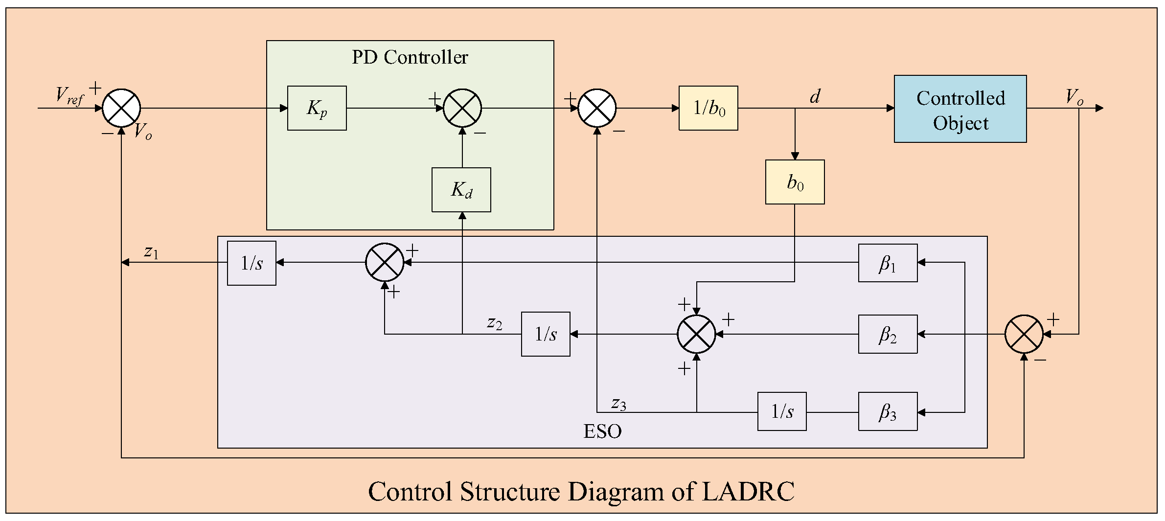
To improve the control accuracy of the Active Disturbance Rejection Control (ADRC), nonlinear functions were employed as the parameters of the observer and controller. Although this led to an improvement in the engineering control quality, it also gave rise to problems such as a complex structure, difficult parameter adjustment, and challenging theoretical analysis. In addressing these issues, scholars such as Gao Zhiqiang, after conducting an in-depth analysis of the control principle and design method of ADRC, proposed a simplified form of the Linear Active Disturbance Rejection Controller (LADRC). While the LADRC retains the merits of the original ADRC, it reduces the utilization of nonlinear functions. Through the linearization treatment of the Extended State Observer (ESO) and Nonlinear State Error Feedback (NLSEF), the control system structure of the LADRC is significantly simplified, and it also brings considerable convenience in parameter tuning and theoretical analysis. The control structure of LADRC is illustrated in
Figure 3.
4. Design of FO-ADRC for Buck Converter
In recent years, fractional-order calculus has been adopted in control theory along with the continuous refinement of control system design. Since the beginning of this century, research scholars have discovered that, compared with the traditional integer-order control scenarios, the controlled systems in fractional-order control possess superior dynamic performance and robustness, which has significantly facilitated the application of fractional-order theory in control engineering domains such as motors and aircraft. In the realm of DC/DC converters, the fractional-order control of the single-voltage closed loop has been accomplished, and better effects have been obtained compared to integer-order control. To further enhance and improve the stability and dynamic characteristics of the Buck converter, in this section, based on the merits of the LADRC and the advantages of fractional-order theory, a fractional-order linear Active Disturbance Rejection Control (FO-LADRC)method based on the output voltage is designed, to elevate the dynamic performance and anti-interference capability of the system.
4.1. Fractional-Order Linear Active Disturbance Rejection Control
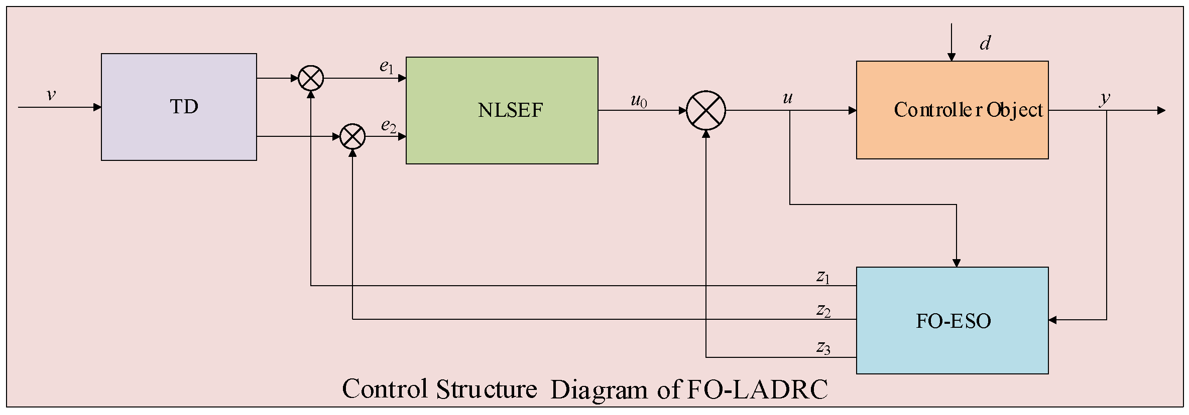
Fractional-order linear Active Disturbance Rejection Control (FO-LADRC) is an extension of linear Active Disturbance Rejection Control (LADRC), which itself is based on integer-order control theory and comprises an error feedback mechanism and an Extended State Observer (ESO). The control structure of FO-LADRC is illustrated in
Figure 4.
To retain the advantages of both PID and LADRC, the FO-LADRC scheme typically incorporates a PD controller as its error feedback mechanism. The key component of FO-LADRC is the fractional-order Extended State Observer (FO-ESO), whose primary function is to estimate and compensate for system disturbances in real time, thereby transforming the system into an integral series structure. This transformation introduces an integral term to the controlled object without explicitly adding an integrator to the system, enabling it to achieve static error-free output. The structural diagram of the FO-LESO is shown in
Figure 5.
The expression for the fractional-order linear Extended State Observer (FO-LESO) can be formulated as follows:
where
e1 is the system error.
z3 is the estimate of the total disturbance
f of the system.
D is the fractional differential operator.
α is the differential order.
β1,
β2, and
β3 are the gain parameters of the FO-LESO and the parameters are unknown and variable.
4.2. Design of Fractional-Order Active Disturbance Rejection Control for Buck Converter
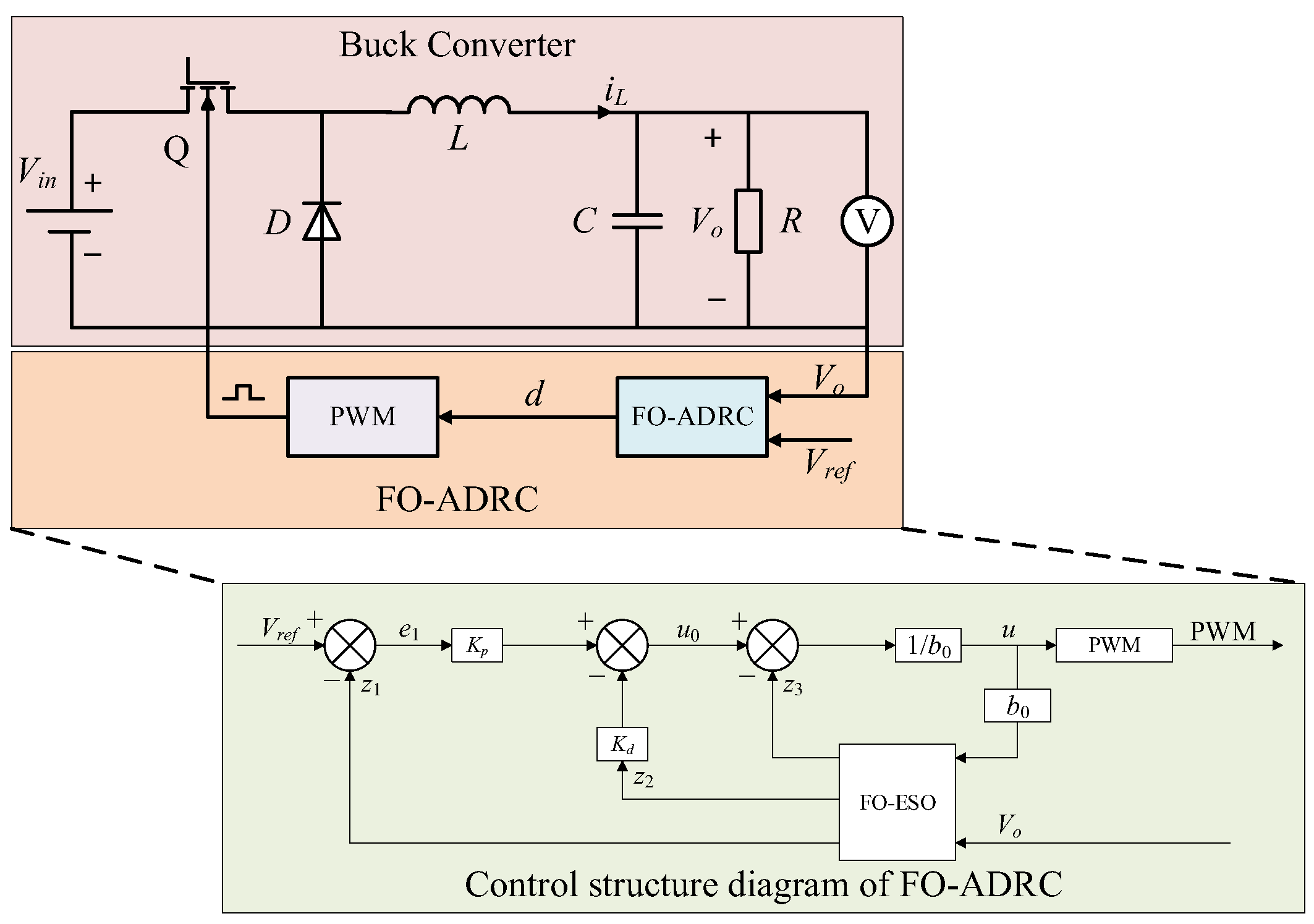
The system control structure of the Buck converter based on FO-LADRC is shown in
Figure 6.
In practical applications, circuit components such as inductors and capacitors in a Buck converter, as well as the input voltage, may be influenced by external environmental factors. The nominal values of the input voltage and load are represented by
Vin0 and
R0. If the total disturbance of the system is denoted as
f, the following state equation can be derived as follows:
where
f is the new state
x3, which denotes the overall disturbance of the system. Assuming that
f is a bounded interference, the equation of the state can be reformulated as follows:
where control quantity
u =
.
b is the system gain. The actual output is
y =
x1 =
Vo.
According to Equation (8), the characteristic equation of the FO-LESO can be obtained as follows:
To enhance the stability performance of the control system and reduce the adjustment time, it is assumed that the ideal characteristic equation can be expressed as follows:
Therefore, the mathematical expression for the relationship between parameters
β1,
β2,
β3, and
ω0 is as follows:
where
ω0 is the bandwidth of the observer. Its value will affect the observation accuracy of the Extended State Observer. When the
ω0 value is high, the accuracy of the observation will also be improved, but the noise signal will also be amplified. Therefore, the choice of the
ω0 value should fully consider the impact of noise on the system.
If the estimation error of
z3 is disregarded, the system can be simplified to a structure of double integral series.
The control quantity
u0 generated by the PD controller can be expressed as follows:
where
Kp and
Kd are the control parameters of the integer order PD controller. According to Equations (11) and (12), the transfer function of the PD control system can be obtained as follows:
The control variable
u, which was obtained through the compensation of disturbance
u0, can be expressed as follows:
4.3. Stability Analysis of FO-ADRC
4.3.1. Stability Analysis Based on System Transfer Function
Based on the structure of the FO-LESO shown in
Figure 5, it can be inferred that the transfer function of the FO-LESO can be expressed as follows:
According to Equation (16), the closed-loop transfer function of the whole system can be expressed as follows:
where
According to Equation (2), the controlled object can be simplified as follows:
where
a1 = 125,
a2 = 2.5 × 10
7, and
b = 2.5 × 10
9. In this paper, the single-parameter tuning method is used to adjust the parameters, which are as follows:
According to Equations (17), (19), and (20), the closed-loop transfer function of the system can be obtained as follows:
where
Ci and
Di (
i = 0, 1, 2….) are shown in
Table 1.
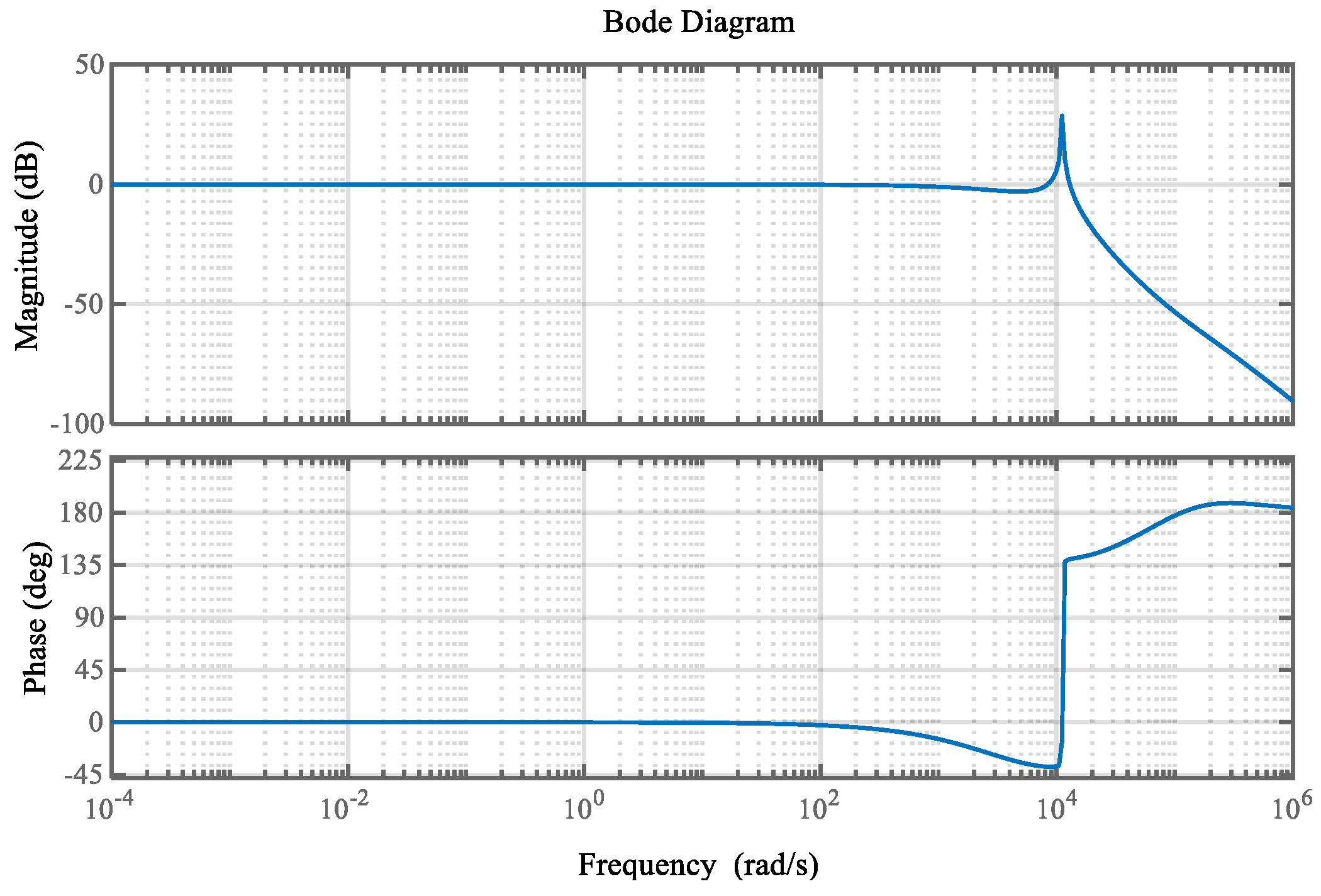
The Bode plot of the system according to Equation (17) is shown in
Figure 7.
As illustrated in
Figure 7, the phase margin of the FO-ADRC system is measured at 141.7959°, with a corresponding frequency of 8.3914 × 10
3 rad/s. The system exhibits minimal steady-state error and high control accuracy in the low-frequency band. In the mid-frequency band, the curve slope is relatively flat, leading to reduced system overshoot and a shorter settling time. Moreover, in the high-frequency band, the curve demonstrates the system’s robust anti-disturbance capability through its low-amplitude response. Consequently, it can be concluded from this analysis that the FO-LADRC system possesses a superior response speed and anti-interference performance.
4.3.2. Stability Analysis Based on Errors
According to Equation (8), the transfer function of
z1,
z2, and
z3 can be obtained as follows:
Let
, the error equation of the state can be derived from Equation (8) as follows:
According to Equation (25), the transfer function of errors
e1 and
e2 is as follows:
According to Equation (8), it can be obtained as follows:
If both
y and
u are considered to be step signals with
y(
s) =
K/
s,
u(
s) =
K/
s, and amplitude
K, the steady-state error of the system can be determined as follows:
As shown in Formula (29), the FO-LESO demonstrates excellent convergence and estimation capabilities, enabling errorless estimation of system state variables and generalized perturbations. This highlights its strong potential for accurate estimation in academic research and practical applications.
5. Simulation and Verification
To verify the effectiveness of the proposed FO-LADRC strategy, the circuit simulation model shown in
Figure 6 was built on the MATLAB 2022/Simulink platform. The specific data are shown in
Table 2.
First of all, to validate the convergence of the error estimation of FO-LADRC, the output waveforms of the system errors
z1,
z2, and
z3 are depicted as shown in
Figure 8. As illustrated in
Figure 8, the systematic errors converge to zero and achieve a steady state within a relatively brief period. Additionally, the duty cycle stabilizes at approximately 0.3.
Secondly, to further verify the superiority and effectiveness of FO-LADRC, simulation verification is carried out in two aspects: the dynamic response and anti-interference performance of the Buck converter.
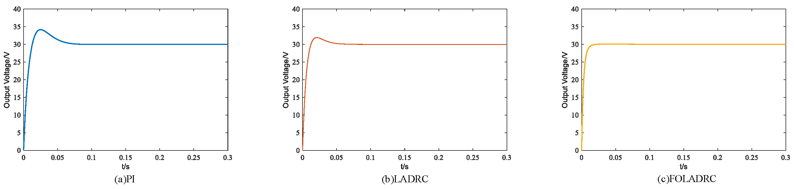
Figure 9 presents the dynamic response of the system. It can be observed from
Figure 9 that the response speed of FO-LADRC during the ascending process of the system is conspicuously superior to that of PI and LADRC. At the same time, for the Buck converter controlled by FO-LADRC, there is essentially no voltage overshoot and it can enter the steady-state time rapidly. Thus, it can be inferred that FO-LADRC surpasses PI and LADRC in terms of response speed, voltage overshoot, and steady-state time.
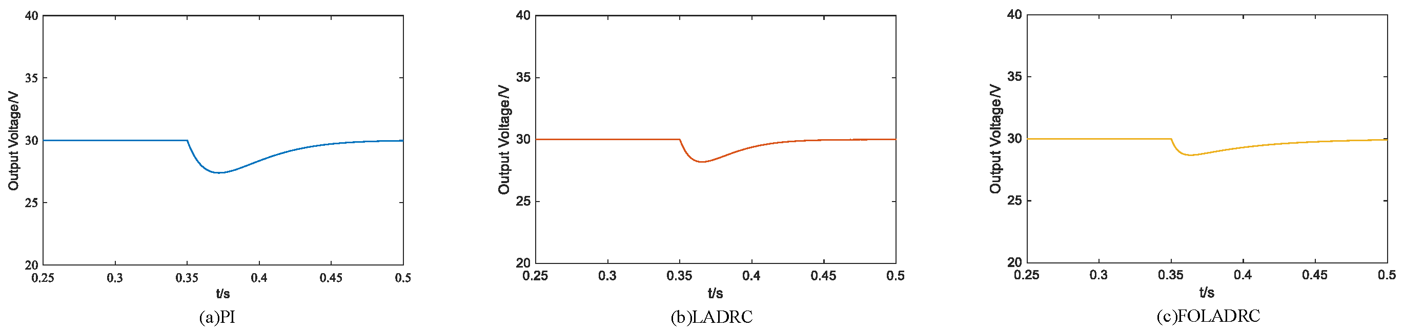
Figure 10 depicts the anti-interference performance of the system. Considering the sudden change in the load resistance R during operation—20 Ω → 15 Ω—the system responses obtained by employing three control algorithms are presented in
Figure 10. It can be observed from
Figure 10 that the regulation time of the system controlled by the FO-LADRC algorithm proposed in this paper when the load changes from 20 Ω to 15 Ω is 0.032 s, and that he voltage fluctuation range is 29.12 to 30 V. For the PI-controlled system, the regulation time when the load changes from 20 Ω to 15 Ω is 0.121 s, and the voltage fluctuation range is 27.82 to 30 V. For the LADRC-controlled system, the regulation time when the load changes from 20 Ω to 15 Ω is 0.082 s, and the voltage fluctuation range is 28.42 to 30 V. Hence, when the load varies, the FO-LADRC algorithm proposed in this paper enables the output voltage to track the reference value more rapidly and stably, and possesses stronger anti-interference performance.
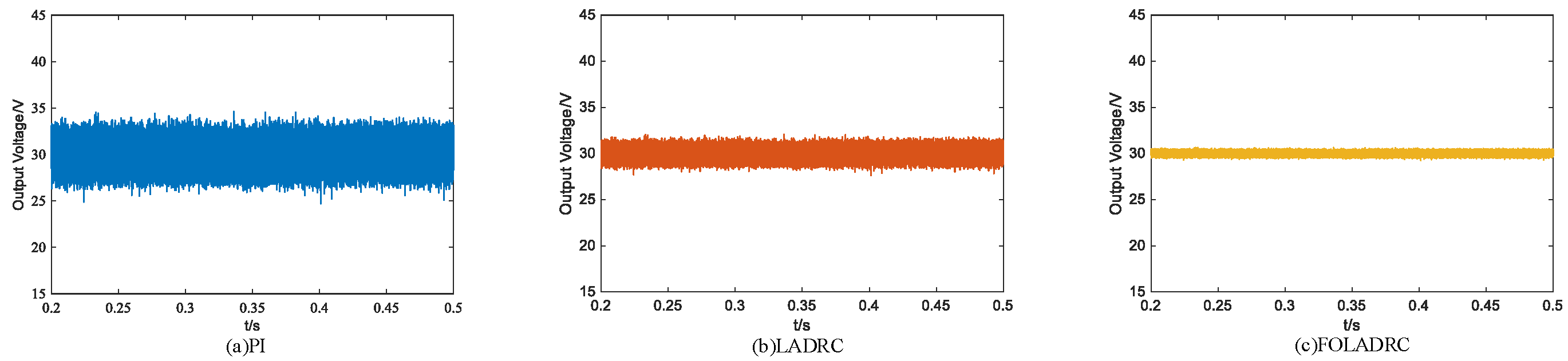
Figure 11 depicts the noise resistance performance of the system. Considering the noise, the system output voltage change obtained by employing three control algorithms is presented in
Figure 11. It can be observed from
Figure 11 that the average voltage fluctuation range of the system controlled by the PI algorithm proposed in this paper is 25.91 to 37.82 V. For the LADRC-controlled system, the voltage fluctuation range is 28.33 to 31.64 V. For the FO-LADRC-controlled system, the voltage fluctuation range is 29.42 to 30.51 V. Hence, when considering the noise, the FO-LADRC algorithm proposed in this paper has the smallest voltage fluctuation range and possesses stronger anti-noise robust performance.
As indicated in
Table 3, the FO-LADRC strategy proposed in this study demonstrates a substantial enhancement in system performance and robustness against disturbances, particularly exhibiting superior anti-interference capabilities in response to abrupt load variations.
6. Experimental Verification
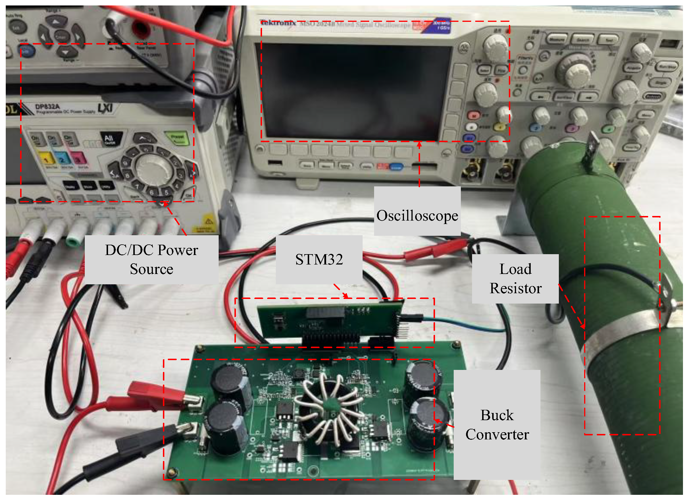
To verify the effectiveness of the control strategy, an experimental platform for the Buck converter system based on STM32 was developed, as illustrated in
Figure 12.
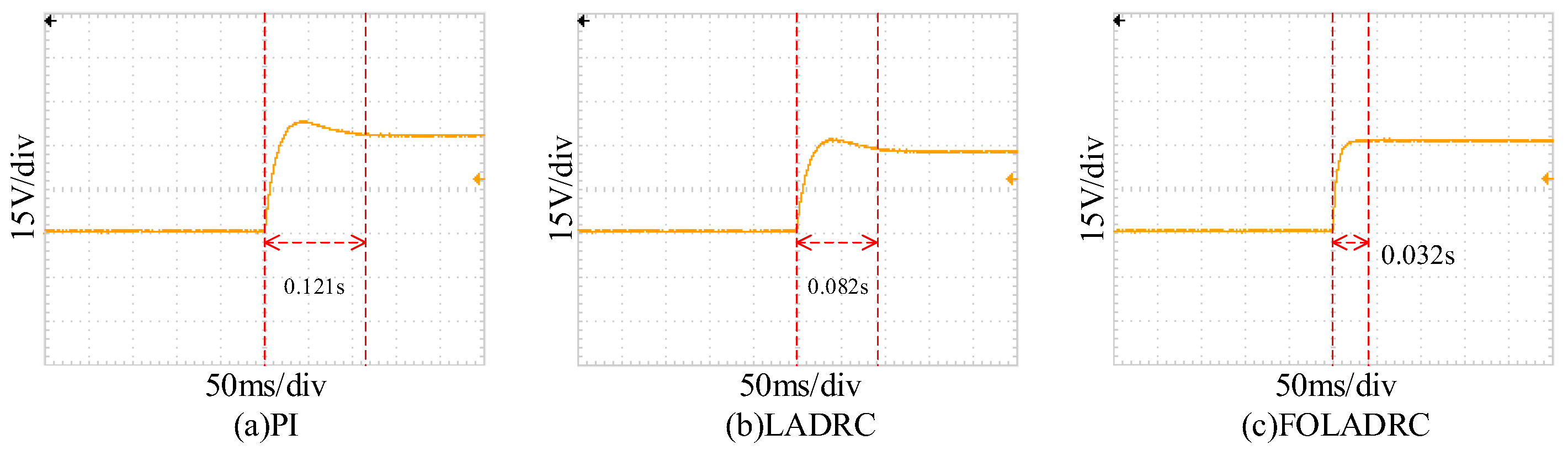
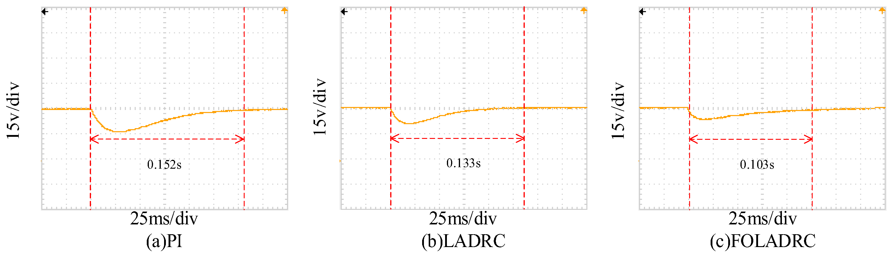
In this paper, dynamic response experiments for the Buck converter system and anti-interference capability tests for the system were carried out separately, as illustrated in
Figure 13 and
Figure 14.
It can be observed from
Figure 13 and
Figure 14 that the control strategy proposed in this paper demonstrates significant superiority over PI and LADRC in terms of response speed, voltage overshoot, and anti-interference capability. The detailed performance metrics are presented in
Table 4.
In the validation section of this paper, the primary focus has been on comparing the proposed fractional-order Extended State Observer with the conventional linear ESO and PI controller. To provide a more comprehensive evaluation, this study further incorporates a comparative analysis against the traditional nonlinear ESO and other control methods through simulation and experimentation. The comparison results are shown in
Table 5. Compared with the existing literature, the control strategy proposed int this paper has the best performance.


