1. Introduction
According to the World Health Organization [
1], visual impairment is defined as a reduction in visual acuity and visual field that cannot be fully corrected. It is systematically categorized into five levels—mild, moderate, and severe visual impairment, blindness, and total blindness—based on internationally standardized criteria for visual acuity and visual field thresholds. The persistent challenges faced by visually impaired individuals during travel have increasingly drawn global attention, revealing the limitations of traditional assistive tools such as white canes and guide dogs. While these assistive means provide foundational support for navigation, their efficacy is substantially restricted in dynamic environments, raising significant concerns [
2]. Users regularly face collision risks and cognitive obstacles when navigating independently, compounded by social and psychological pressures [
3].
These traditional tools demonstrate notable deficiencies, particularly in their limited obstacle detection range of approximately 1.2 m and difficulty identifying obstacles positioned above ground level [
4]. This tactile detection technique requires being near obstacles, which unintentionally increases the risk of collisions [
5]. Moreover, the anxiety and constant alertness resulting from insufficient obstacle awareness not only heighten physical risks but also negatively impact mental well-being [
6,
7]. The social stigma associated with the noticeable white cane is particularly concerning. Its visibility often labels individuals, drawing undeserved attention and potentially discouraging their independence [
8,
9,
10]. This issue leads to a broader social exclusion that undermines the inclusivity of public spaces [
11,
12].
With emerging technological solutions, RGB-D camera-based navigation technologies appear promising, offering significant enhancements in perception range and environmental recognition capabilities [
13]. However, existing auxiliary devices that utilize this technology have yet to overcome critical issues. Primarily, the established design retains the stigmatizing stick structure. Additionally, information overload and inadequate real-time performance diminish their utility [
14]. The cumbersome nature of most wearable devices further limits their practical application in daily life.
This study aims to develop a highly efficient wearable device optimized for intelligent navigation. Key innovations include introducing a non-stick structural design to lessen dependence on disability labels; integrating sensors such as RGB-D cameras into lightweight arm-mounted devices that include a gimbal system to reduce fatigue; utilizing optimization algorithms for real-time obstacle detection and classification; and developing a multimodal interaction system that ensures the effective communication of navigation instructions through an intelligent information screening mechanism.
Assessing these challenges and innovations underscores the critical need for a shift in the design of assistive technologies for the visually impaired, focusing not only on functionality but also on social inclusivity and the comfort of users.
2. Related Work
In recent years, the design of assistive devices has increasingly prioritized de-stigmatization, aiming to facilitate the social integration of individuals with disabilities. This shift seeks to mitigate the adverse effects of the traditional “disability label” associated with assistive technologies, emphasizing functionality and esthetics that align more closely with societal integration rather than highlighting the user’s disability [
15,
16].
The work of Pieter Desmet (2015) illustrates this perspective by focusing on emotion-centered design in wheelchair development. His findings indicated that users and their families often prefer designs that obscure the “disability” aspect, such as concealed push rods that reduce the visibility of the wheelchair’s functional components [
17]. Similarly, integrated umbrella-shaped crutches allow individuals with limited mobility to use these aids more discreetly, reducing the psychological burden associated with traditional crutches [
18]. Phonak Sky hearing aids further illustrate this trend, adopting vibrant, stylish designs that resemble personal accessories instead of medical devices. At the same time, some models integrate functionality discreetly within glass frames, minimizing visibility and associated social stigma [
19].
These examples illustrate an increasing trend in research that emphasizes the need for de-stigmatization in the design of assistive devices. Nevertheless, recent developments in assistive technologies for visually impaired individuals mainly focus on obstacle detection and perceptual support. Ultrasonic sensors are commonly employed due to their affordability and ease of integration. For instance, Y. Wang et al. integrated these sensors into a traditional white cane, providing users with auditory notifications regarding low-hanging obstacles [
20]. Similarly, Patil et al. developed ultrasonic obstacle-avoidance boots equipped with multiple sensors for multidirectional coverage, employing vibrational feedback as alerts [
21]. S. Gallo et al. proposed a multimodal white cane that integrates ultrasonic, infrared, and sonar sensors for comprehensive obstacle coverage; however, it often struggles with limited detection ranges and low accuracy in obstacle localization [
22].
In contrast, millimeter-wave radar technology offers enhanced detection capabilities, as demonstrated by Kiuru et al. with their radar-assisted obstacle avoidance system [
23]. However, alternative solutions, such as laser rangefinders used by Carolyn et al., exhibit low spatial resolution and high costs, which limit their practical deployment due to integration complexities [
24]. Recent studies have also explored the potential of RGB-D cameras and stereo-vision technologies to enhance environmental perception. Orita et al. developed this idea by introducing a cane integrated with an RGB-D camera that uses vibrational feedback to convey information about obstacles [
25]. Y. Cang et al. advanced a collaborative robotic cane that combines camera input with force feedback mechanisms to assist users [
26]. Nonetheless, the weight of these designs is a significant disadvantage, making their prolonged use uncomfortable.
Research has also explored wearable devices, as demonstrated by Rodriguez et al., who utilized stereo cameras in their navigation system that employs bone conduction audio feedback to reduce external noise interference [
27]. Y. Lee et al. presented a vest-style navigation system that integrates an RGB-D camera with inertial measurement units (IMUs) to provide practical guidance through vibrational signals [
28]. Similarly, Shehabi et al. designed an indoor navigation device that utilizes a Kinect camera for feedback through a vibrating belt [
29]. Despite these innovations, wearable devices often remain bulky and complex, which leads to stability challenges and low accuracy during outdoor use.
The deployment of object detection systems based on computer vision, particularly the YOLO series’ single-stage detection algorithms, has emerged as a preferred approach for recognizing obstacles in assistive systems for the visually impaired [
30]. These deep learning frameworks can process data at real-time speeds of 25 to 31 frames per second while maintaining high accuracy, which is essential for dynamic environments [
31]. Nonetheless, challenges persist in optimizing detection accuracy and achieving efficient real-time processing on resource-constrained wearable devices.
Despite the high-resolution capabilities of RGB-D cameras, existing intelligent aid devices often do not effectively address social stigma [
32]. Many still adopt a cane-like structure that is visibly identifiable, perpetuating disability labels. Furthermore, wearable technology can be cumbersome due to fixed angles, which cause camera shake and make usage more challenging for users’ navigation. Existing feedback systems often suffer from complexity and inefficiency, making it difficult to identify specific obstacles [
33]. This presents challenges for users attempting to establish a spatial understanding.
This study aims to design an innovative, intelligent navigation wearable device utilizing RGB-D technology. It emphasizes efficiency, enhancing environmental perception through advanced algorithms and improving interaction methods to streamline user navigation information delivery.
The key innovations and contributions of this study include the following:
De-Stigmatization Design: abandoning the traditional stick structure to minimize disability labels and reduce the psychological impacts of social stigma.
Lightweight and Portability: creating a lightweight, easy-to-wear device that addresses the bulkiness and rigidity of conventional assistive devices, integrated with a PID gimbal system for stabilization while allowing for natural arm movement.
Real-Time Environmental Perception: employing high-precision sensors and optimized algorithms to detect the location and category of obstacles in real time to improve travel safety.
Multimodal Interaction System: providing vibration and voice multi-sensory feedback for an improved user interaction experience with the obstacle avoidance algorithm ensuring efficient information transmission.
3. Methodology
This section outlines the methodology for developing an intelligent navigation wearable device prototype (INWDP) for visually impaired individuals. It includes critical components such as obstacle detection, dynamic avoidance strategies, and multimodal interaction. The system ensures effective and safe navigation by integrating advanced sensors and implementing real-time processing. The subsequent sections provide a thorough overview of how each module is implemented and the methods employed to enhance performance.
3.1. Overall Architecture of INWDP
As shown in
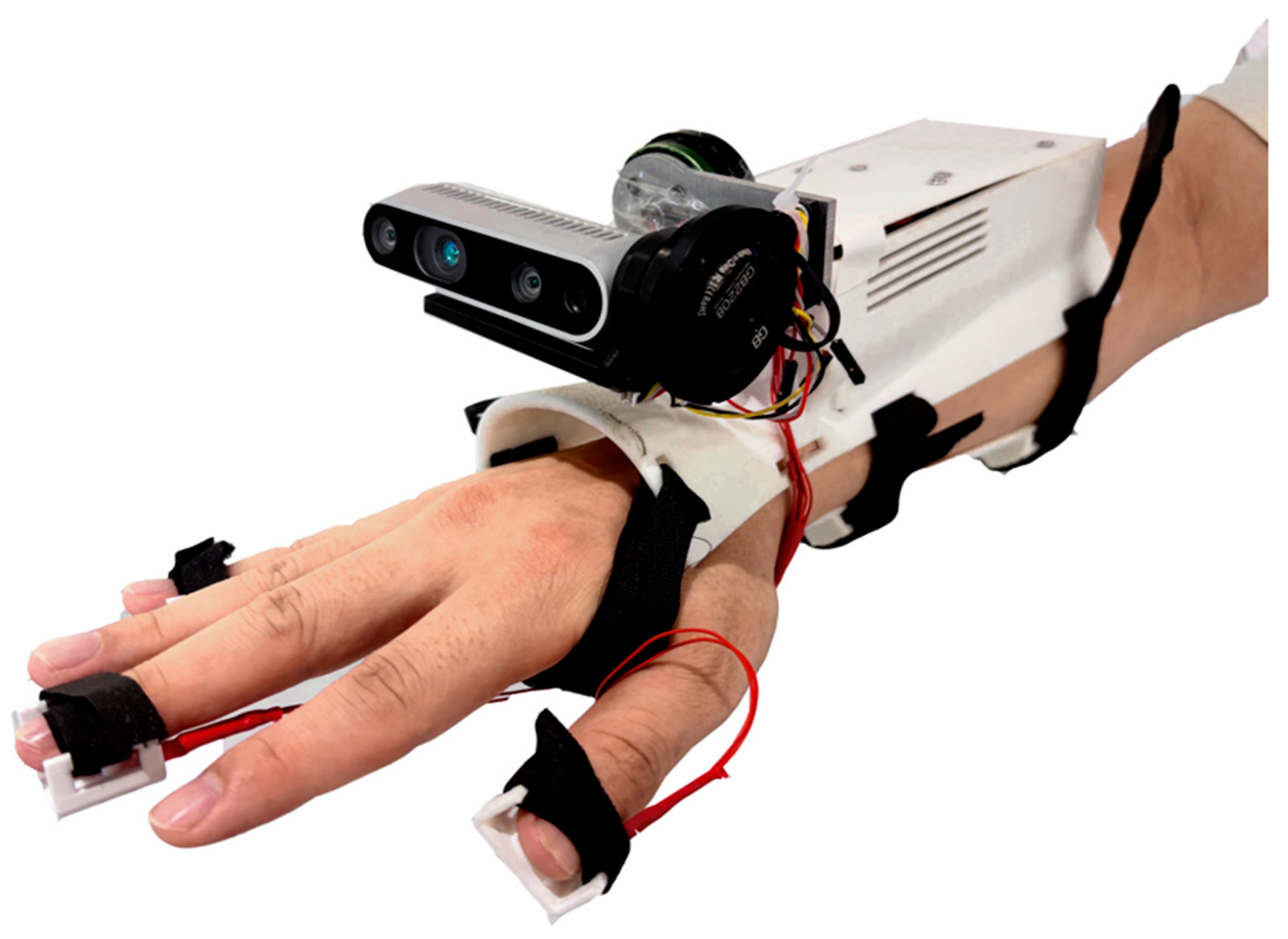
Figure 1, the INWDP consists of three core modules: the sensor perception module, the controller processing module, and the actuator module. These modules interact through wired interfaces or Bluetooth, promoting high cohesion and low coupling within the system.
The system uses the Intel RealSense D435i depth camera, which provides stable depth data at a resolution of 1280 × 720 pixels and a frame rate of 90 FPS. This enables rapid system response and precise data accuracy. The camera features a wide field of view, covering around 87° horizontally, 58° vertically, and 95° diagonally, which ensures an extensive spatial awareness crucial for navigation. The weight of the camera is approximately 91 g, featuring a compact structure, low power consumption, and easy integration into embedded devices for obstacle detection and avoidance navigation. The IMU6050, used for the PID gimbal in this system, is designed for low-cost, short-duration, low-precision situations. Through the I2C interface communication, real-time angle data are continuously provided for the gimbal. The built-in IMU of the depth camera offers a reference for coordinate correction in point cloud generation.
The computing core uses the Intel Alder Lake N100 mini-host, recognized for its compact size (142 × 61 × 21 mm) and powerful processing capabilities. With support for USB 3.2 connectivity, it efficiently processes depth and image data, integrates and analyzes environmental information, and generates navigational instructions. The Arduino UNO acts as the control unit, powering the vibrational feedback system in the finger sleeves and modifying the gimbal’s motor angle using IMU data to ensure camera stability.
The TC4452DF N08 driver accurately controls the gimbal motor for precise adjustments. The system includes three vibration finger sleeves consisting of small vibration sheets with a compact structure and strong vibrations, which provide haptic feedback to the user as part of the interaction design.
The fastening method for the INWDP features an integrated design that combines the bottom of the controller package box with the upper fixing plate. These plates conform to the arm’s curvature and are fastened with Velcro bands, accommodating various arm sizes. The vibrational feedback mechanism is strategically positioned on the thumb, middle, and little fingers to enhance tactile interactions.
Figure 2 shows the physical prototype worn by a user.
The total weight of the INWDP is approximately 480 g, and the fastening bands are evenly distributed along the arm. During use, the arm naturally droops. The direction of the force experienced by the hand aligns with gravity, with the force point located at the shoulder. This situation resembles a user lifting an object weighing 480 g, which feels more comfortable.
3.2. Camera Gimbal Design and Implementation
The stability of the depth camera is crucial for accurate environmental data acquisition; however, the camera shaking during its movement can compromise this stability. Additionally, maintaining a fixed arm posture can lead to increased fatigue. To address this, a camera gimbal is integrated to adjust the camera angle automatically, reducing arm fatigue while ensuring consistent camera data stability.
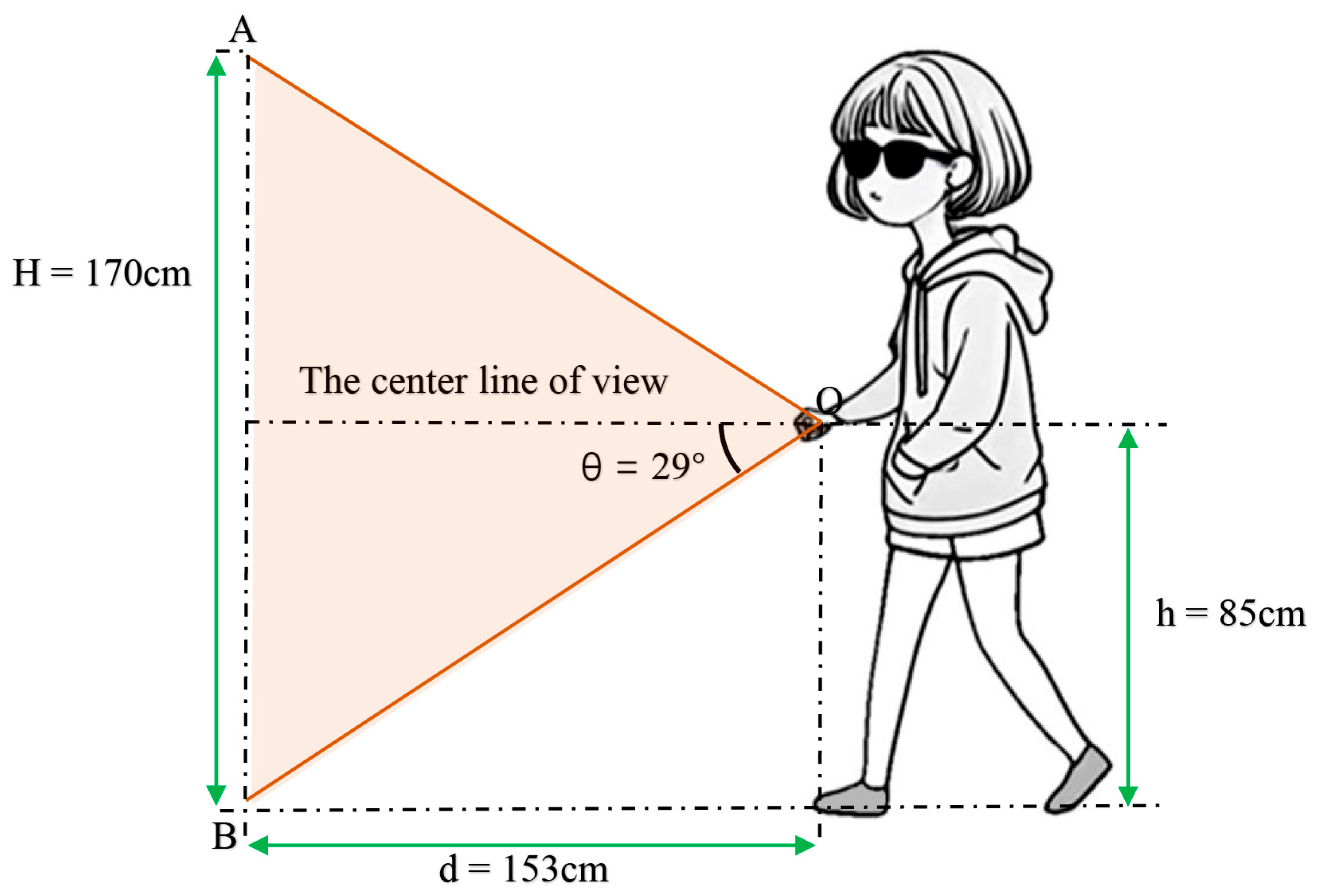
When the INWDP is worn, the depth camera is positioned at approximately half of the user’s height. For validation purposes, teens measuring approximately 170 cm in height are the focus subjects. In this scenario, the height of the depth camera mounted on the wrist is 85 cm above the ground. The orientation and placement of the depth camera are shown in
Figure 3, supporting the design’s rationale and ergonomic considerations.
Point O indicates the location of the depth camera, with the center line of view projecting parallel to the ground in a horizontal orientation. The vertical field of view, measuring 58°, symmetrically bisects this center line of view. The lower boundary of this visual field intersects the horizontal ground at Point B. In contrast, the upper boundary intersects vertically at Point A. In this context, h represents the camera’s height above the ground, d is the horizontal distance from Point O to Point B, H indicates the maximum height of Point A from the ground, and θ, the angle between the visual field boundaries and the horizontal line, measures 29°.
In this configuration, the horizontal distance d represents the range of the unobservable area, while the height H indicates the maximum obstacle height that can be detected at the margin. The following formulas mathematically define these relationships:
According to this formula, for a 170 cm-tall teenager with a depth camera located at the wrist (85 cm above the ground), the calculated unobservable area distance, is 153 cm. The maximum height () of obstacles that can be detected at the boundary of the unobservable area is 170 cm. Therefore, the detection range is designed to accommodate the user’s height obstacles. Although the unobservable area distance is 153 cm, obstacles can be identified before reaching this area, improving the proactive navigation ability. Furthermore, adjustments to the user’s height affect the maximum height of detectable obstacles when the depth camera is positioned at the wrist level, which is half the user’s height. This ensures detection obstacles at the unobservable zone boundary up to the height of the head, irrespective of the user’s height variations.
In this wearable system, the gimbal primarily stabilizes the camera in the pitch angle direction. While generating a point cloud, the depth camera’s integrated IMU adjusts the coordinate system according to attitude angles, correcting roll direction deviations. As a result, the gimbal control strategy prioritizes precise pitch angle control for maintaining camera stability.
Figure 4 shows the control block diagram of the gimbal system.
The PID controller calculates the control signal V by evaluating the difference between the actual pitch angle (real-time IMU readings) and the desired pitch angle (set value). This signal regulates the gimbal motor, ensuring camera angle stability. The following algorithm determines the PID control signal:
In this algorithm, is the proportional control coefficient, is the integral control coefficient, is the differential control coefficient, and represents the error at the time t. This approach ensures the depth camera’s consistent performance, which is crucial for accurate environmental data acquisition and the effective operation of the intelligent navigation system.
System stability is fundamentally characterized by the ability to converge asymptotically without exhibiting oscillations or divergence. Responsiveness is assessed by the system’s rise time and settling time, indicating how quickly the desired value is reached.
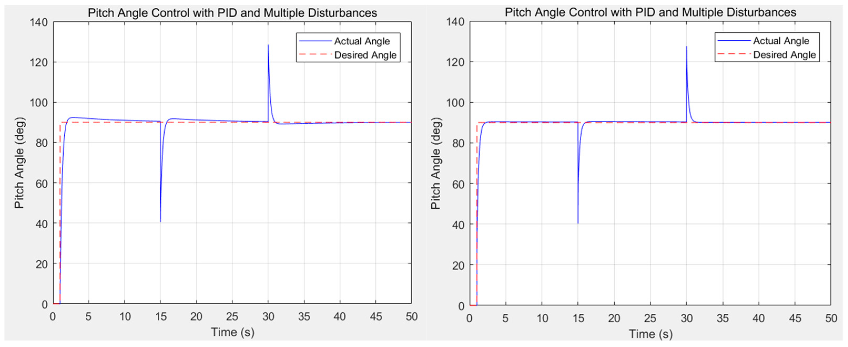
To evaluate the gimbal system’s capability in maintaining camera balance, a simulation was conducted in which the desired pitch angle was set to 90°. The initial pitch angle was maintained at 0° during the time interval of 0–1 s. At 1 s, the PID control algorithm was activated, prompting the system to automatically adjust the pitch angle and stabilize it at the desired value of 90°. Subsequently, to simulate the system’s response to large external disturbances, abrupt changes were introduced: at 15 s, the actual pitch angle was instantaneously reduced by 50°, and at 30 s, it was increased by 40°.
The performance of the system under various sets of PID parameters was evaluated through simulation. Improper PID tuning, as shown in
Figure 5, results in significant overshoot and excessive settling time, causing delays in pitch angle adjustment. This limits the system’s applicability in real-time navigation devices. In contrast, with appropriate PID parameters, the system exhibits stable, accurate, and fast performance, as shown in
Figure 6. The steady-state error approaches zero, and the system responds rapidly to disturbances, maintaining angle stability.
3.3. Obstacle Detection
The attitude angles obtained by the IMU sensor and the depth image captured by the RGB-D camera are processed by the obstacle detection algorithm to obtain the obstacle information in the environment. The overall workflow of the obstacle detection process is shown in
Figure 7.
The original point cloud data consist of a substantial number of points, making direct processing complex and computationally intensive. Therefore, filtering and preprocessing are essential. This study employs voxel grid filtering and statistical filtering to reduce point cloud density and eliminate outliers. Specifically, voxel grid filtering reduces the number of points through spatial voxelization while preserving the overall structure of the point clouds. Meanwhile, statistical filtering uses neighborhood statistical information to discard noise points and enhance data quality. The effect of preprocessing, including point cloud filtering and downsampling, is illustrated in
Figure 8.
Following the filtering and downsampling processes, the remaining ground point clouds largely dominate the dataset, which may interfere with effective obstacle detection. To address this, the Random Sample Consensus (RANSAC) plane fitting algorithm and point cloud rasterization techniques are used further to eliminate ground point clouds after the initial processing. The RANSAC plane fitting algorithm randomly selects three points from the point cloud to establish a candidate plane. The algorithm iteratively fits a plane that contains the maximum number of internal points, identifying the largest plane in the point cloud. If the angle between the normal vector of this maximum plane and the direction of gravity is less than 20 degrees, it is categorized as the ground. All internal points below this threshold are eliminated, leading to the extraction of non-ground point cloud data.
Considering that noise in long-distance and high-intensity light environments could affect the depth camera, a dynamic adaptive threshold is implemented. This threshold adjusts ground point detection based on various rasterized positions, enhancing the ground removal process, as illustrated by the following equation:
In the above equation, “” refers to the criterion for eliminating ground point clouds, indicates the grid position of the point cloud, and represents the maximum distance for ground point distribution. Points falling within this distance are classified as ground points, while those exceeding it are labeled as non-ground points.
Figure 9 illustrates the effectiveness of the RANSAC ground removal process.
Once the ground points are removed, the Density-Based Spatial Clustering of Applications with Noise (DBSCAN) clustering algorithm, enhanced by the KD-tree structure, is used to identify obstacles. The DBSCAN clustering algorithm can identify arbitrarily shaped clusters and demonstrate performance robust to noise through a point density evaluation. The KD-tree structure improves neighborhood search efficiency in the DBSCAN clustering algorithm, reducing its time complexity from
O (n
2) to
O (
nlog
n). This enhancement improves the overall algorithm performance, satisfying the needs of real-time applications. Algorithm 1 shows the optimized DBSCAN pseudocode with KD-tree structure acceleration.
| Algorithm 1: Pseudo-code. |
Input: Point cloud dataset(D), Eps, MinPts
Output: Cluster labels(C)
1. Build a KD-tree for efficient nearest neighbor search on D
2. Initialize cluster label with all points marked as unvisited
3. Set cluster_id = 0
4. for each unvisited point ‘p’ in ‘D’:
Mark ‘p’ as visited
Use KD-tree to find all points in ‘eps’ neighborhood of ‘p’
if the number of neighbors < MinPts:
Mark ‘p’ as noise
else:
Increment ‘cluster_id’
Expand cluster by ‘Function expand_cluster’
Function expand_cluster(p, neighbors, cluster_id):
1. Assign ‘p’ to ‘cluster_id’
2. for each neighbor ‘q’ in ‘neighbors’:
if ‘q’ is not visited:
Mark ‘q’ as visited
Use KD-tree to find all points in ‘Eps’ neighborhood of ‘q’
if the number of neighbors < MinPts:
Add the neighbors to ‘neighbors’ list
if ‘q’ is not yet assigned to a cluster:
Assign ‘q’ to ‘cluster_id’ |
The end-to-end delay involved in capturing a single frame depth image from the depth camera to the completion of point cloud generation and obstacle information processing ranges from 15 to 20 milliseconds. Under continuous and stable operational conditions, the system achieves an environmental sensing data throughput of 50 to 66 frames per second (fps).
3.4. Obstacle Target Recognition
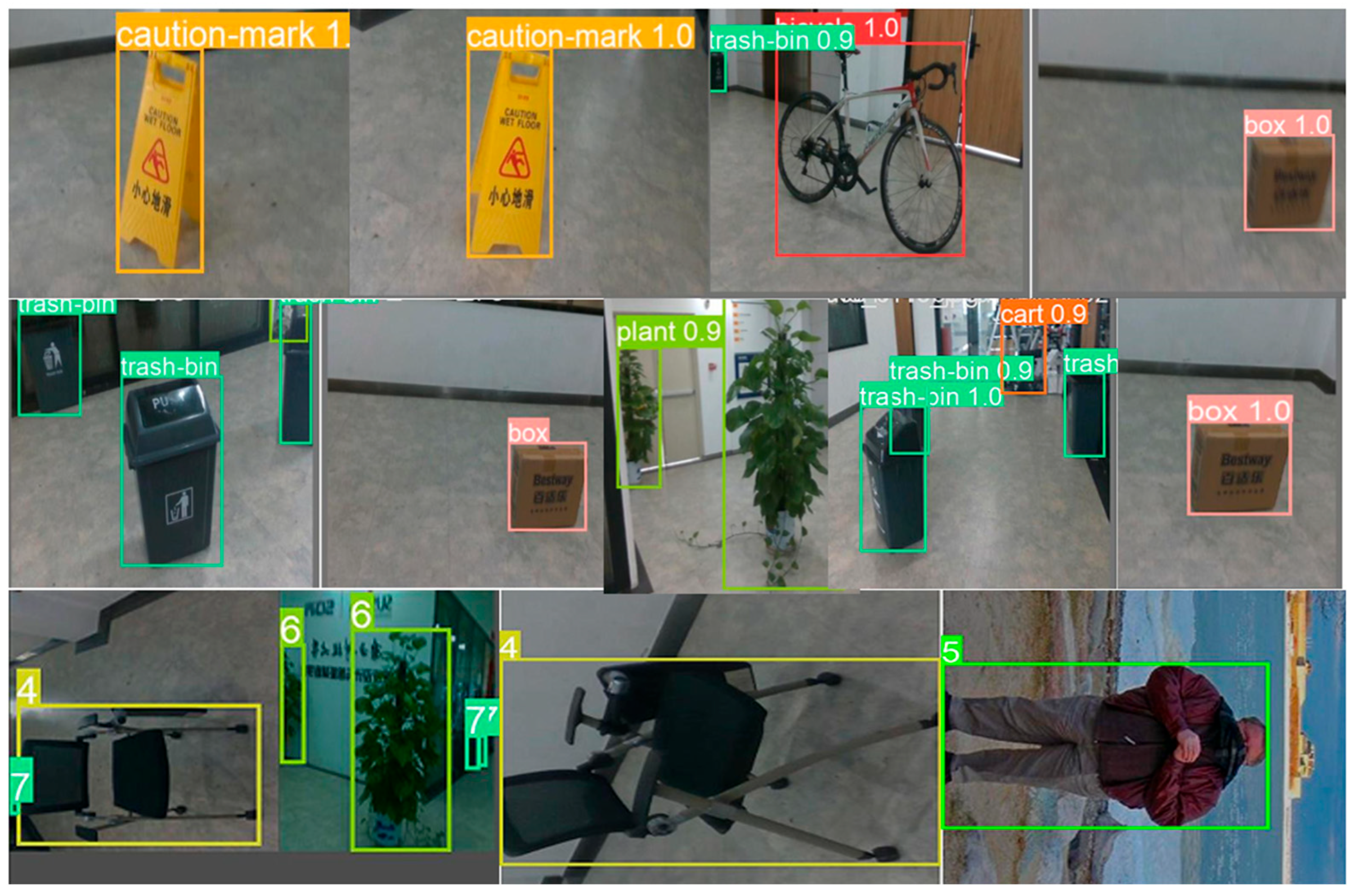
In this study, the primary device for image data collection was the Intel RealSense D435i depth camera, which was operated through a Python (3.13.3) script on an Intel(R) Core (TM) i5-7300HQ CPU @ 2.50GHz to capture images of obstacles. Before creating the dataset, a survey of common obstacles encountered on school paths was conducted, leading to the selection of several representative obstacles for image acquisition, including pedestrians, bicycles, signs, garbage cans, plants, and chairs. These obstacles were strategically placed in the experimental setting, with the camera mounted on the arm of the data gatherer.
The Python script initiated a video stream from the camera, simulating the walking process of a visually impaired individual at a rate of 3 frames per second. The image gatherer approached the obstacles from various angles and under different lighting conditions, ultimately capturing a total of 2157 images. Data augmentation techniques expanded this initial dataset to 5195 images, which were then divided into training, validation, and test sets according to an 8:1:1 ratio. Each image in the dataset was manually labeled with the corresponding obstacle categories.
To create obstacle recognition models, various You Only Look Once (YOLO) networks were utilized for training on the developed datasets, producing different outcomes among the models. The experimental configuration included an Intel Xeon Gold 5418Y CPU and an NVIDIA RTX 4090 GPU, both running on the Ubuntu 20.04 platform, with training executed using PyTorch 1.11. For each YOLO model, the initial learning rate was set to 0.01, the batch size to 16, and the total number of training epochs to 100. As a result, this process led to the development of multiple target recognition models based on distinct YOLO network architectures.
During the training of the YOLOv8n algorithm model, the loss function value gradually decreased and eventually stabilized. The final precision reached 0.955, the recall rate was 0.926, and the average precision mAP50 was 0.953, and the mAP50-95 was 0.881. The overall performance effect was good, as shown in
Figure 10.
The models were evaluated using metrics such as precision, recall, mean average precision at 50 (mAP50), and mean average precision across IoU thresholds ranging from 50 to 95 (mAP50-95).
Precision and recall, respectively, quantified the model’s ability to correctly identify positive samples and to capture all actual positive instances. Due to the inherent trade-off between precision and recall, relying on a single metric may have led to an incomplete assessment of the model’s effectiveness. Therefore, this study adopted mAP as the primary evaluation indicator, as it provided a balanced and holistic measure by averaging the AP values across all categories.
Performance results for each method are summarized in
Table 1. The experimental results indicate that YOLOv8n outperformed others in accuracy and real-time execution, with an mAP50 of 0.953 and an mAP50-95 of 0.881.
Additionally, the detection rates for 800 selected obstacle images were evaluated using various image detection methods, as shown in
Table 2. The YOLOv8n model demonstrated a detection speed of 34.8 milliseconds per image, outperforming other versions regarding responsiveness.
The tests performed on the various YOLO models validated their capacity to identify obstacle names correctly. Moreover, the models had minimal differences in memory usage and average power consumption, leading to a negligible impact on experimental results. Therefore, the system uses the YOLOv8n model, providing the fastest processing speed with the best recognition accuracy. The end-to-end delay from obtaining a single RGB image from the depth camera to completing the object recognition process is approximately 30 milliseconds. This enables a continuous, environment-aware data throughput of 33 frames per second (fps) under stable operating conditions.
This study employed YOLOv8n to optimize obstacle detection and integrated homemade datasets to enhance model generalization capabilities, achieving high-precision and low-latency detection. The experimental results confirm the advantages of YOLOv8n, offering reliable environmental perception capabilities for visually impaired individuals, enhancing travel safety, and providing technical support for future wearable navigation solutions.
3.5. Intelligent Interaction Realization
The primary objective of this study is to facilitate safe travel for visually impaired individuals through intelligent obstacle avoidance and effective vibration interaction. To address obstacle detection and interaction, the system incorporates priority information screening to convey navigation guidance while efficiently minimizing unnecessary interference.
(1) Target obstacle determination: To avoid information overload during interactive transmission, the system selects only the closest obstacle within a 3 m radius that presents a risk of contact as the target obstacle for each interaction. The detection process scans all obstacle point cloud clusters, focusing on those within the designated travel area. The system calculates the distance between each obstacle and the user, identifying the nearest obstacle as the target.
(2) Obstacle avoidance strategy: Based on the defined travel area, the system selects the direction for obstacle avoidance, considering the positional relationship between the user and the obstacle. The turning distance corresponds to the side of the travel area that maintains the maximum distance from the obstacle’s most hazardous side.
Figure 11 shows that the shaded region represents the user’s position while holding the INWDP before avoiding an obstacle. To avoid the identified obstacle in the travel area, the user moves to the left. The right edge of the yellow travel area illustrated in the figure determines the turning distance.
The calculations for the turning distances are defined as follows:
In the equation,
represents the horizontal coordinate of the target obstacle’s leftmost edge, and
represents the horizontal coordinate of the center line.
In the equation, represents the horizontal coordinate of the target obstacle’s rightmost edge.
The relative sizes of
and
determine the direction of the turn. If
is smaller, the user turns left; if
is smaller, the user turns right. The lateral distance
required for obstacle avoidance steering is calculated as follows:
where
indicates the horizontal coordinate of the left boundary of the travel area, and
denotes the horizontal coordinate of the right boundary.
(3) Vibration rule design: The system uses three vibrating finger sleeves to instruct users on obstacle avoidance maneuvers. Vibration patterns correspond to left and right turn instructions: the activation of the left motor indicates a left turn, while the activation of the right motor indicates a right turn. The vibration from the middle motor signifies the degree of displacement required for turning, with the intensity varying based on the necessary steering. Each user’s actual step size can be incorporated into the system’s parameters, which can be adjusted in the source code. The vibration signals indicate the appropriate direction for obstacle avoidance without specifying the left or right positions of the obstacles. This design reduces the user’s cognitive load. The three vibration motors are designated as the left motor (L), middle motor (M), and right motor (R). The vibration rules are summarized in
Table 3.
This system’s intelligent interaction optimizes information screening to deliver only the most crucial obstacle details. This method minimizes irrelevant distractions, enabling users to focus on essential travel conditions. By analyzing the spatial relationships between obstacles and the travel zone, the system can make informed choices and adaptively alter the route for obstacle avoidance. Furthermore, intuitive vibration prompts effectively communicate travel directions, reducing the cognitive load on users and improving their response times and operational efficiency.
4. Experiments
The INWDP was tested, and experiments were designed to compare the differences in vibration and voice interaction. At the same time, the usage functions of the INWDP were compared with those of the ultrasonic cane and the traditional cane, verifying its effectiveness and advancement in this study. At the same time, a test questionnaire analysis was conducted to verify the practicality and effectiveness of the improved functions for visually impaired people.
4.1. Comparison of Interaction Efficiency
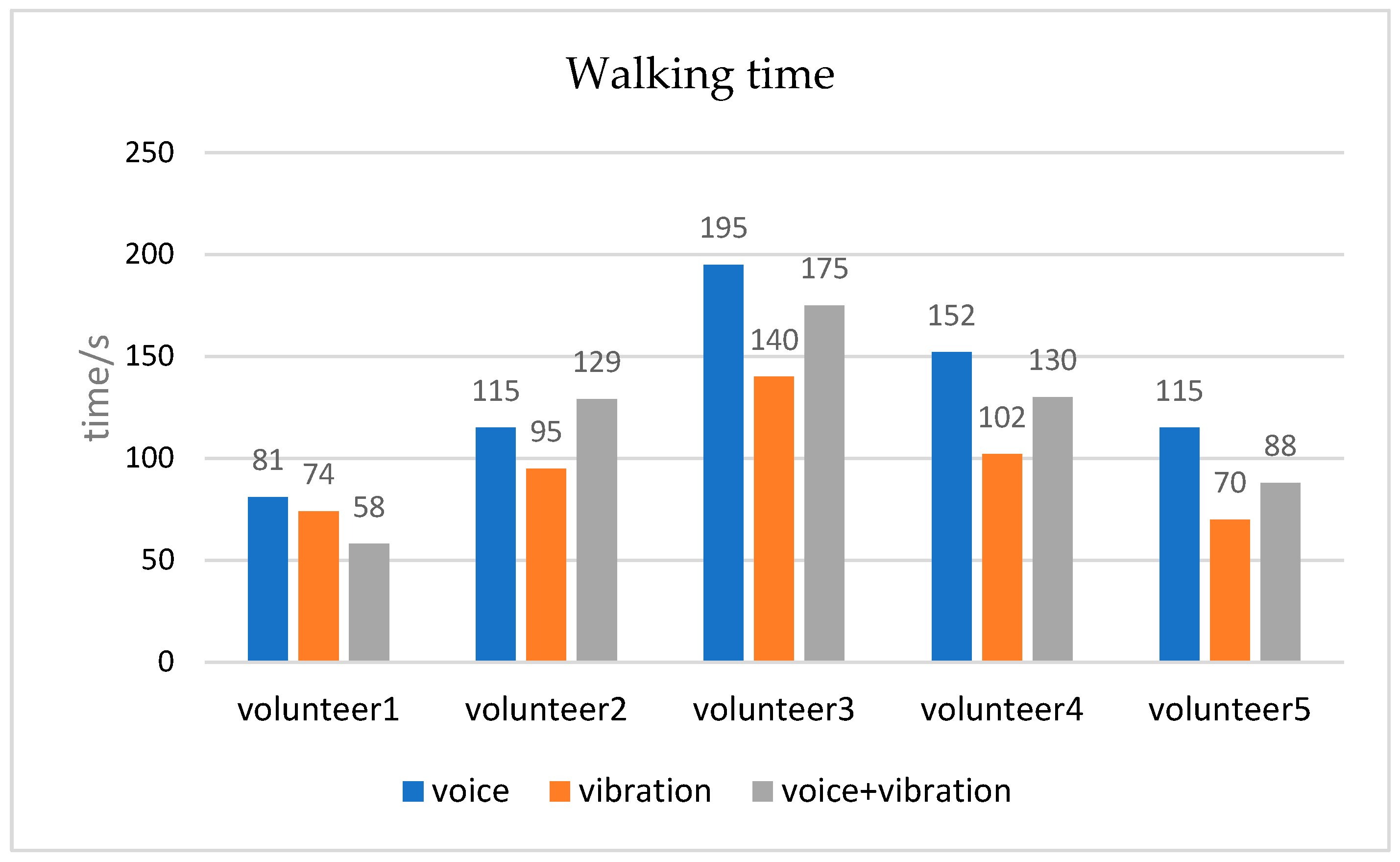
In order to avoid possible ethical risks in using product prototypes for testing by visually impaired people, such as potential physical harm, volunteers with normal vision were recruited to simulate the visual impairment status. To ensure that the key needs of visually impaired users could be replicated and prototypes tested in a controlled environment, the volunteers were blindfolded to simulate individuals with the most severe category of visual impairment, using the INWDP, and tested in a controlled space (16 m × 3.5 m) with fixed obstacles. If individuals with the most severe category of visual impairment are able to travel with the aid of assistive tools, it can be inferred independently that such tools are sufficient to meet the mobility needs of visually impaired individuals across all categories of impairment. Five volunteers (three males and two females, aged between 18 and 26 years, all with normal vision) were recruited for the experiment to assess the impact of voice interaction, vibration interaction, and the combination of both on walking efficiency. Each participant completed three trials involving voice interaction, vibration interaction, and their combination, with recorded walking times. Post-experiment interviews were conducted to collect qualitative feedback on user experience, which was subsequently documented.
Data Analysis: The results of the interaction efficiency experimental data are illustrated in
Figure 12. The vibration interaction method was the most efficient, with the shortest walking time and the highest walking efficiency. Voice interaction produced the longest walking time and the worst efficiency. However, the interaction mode of the combination of speech and vibration was between vibration interaction and speech interaction in the walking rate. Based on the interview records, it was found that the test volunteers unanimously agreed that the prompts for vibration interaction were straightforward and they did not need to spend time listening to the content of the voice broadcast, so the walking speed was faster. However, under the voice interaction method, the waiting time for the voice broadcast increased, and the speed was slow.
Interview Analysis: The test volunteers’ feedback on the usage experience of the INWDP mainly focused on three aspects:
Multi-sensory Interaction: Although voice interaction slows down progress, it can predict the categories of obstacles in advance, enhancing the sense of space and thus reducing fear. Vibration feedback provides very timely guidance and is very useful for obstacle avoidance.
Lightweight Casing and Labor-saving Use: The INWDP is relatively lightweight. Compared with the traditional white stick, which requires waving the stick back and forth, the INWDP can significantly save physical strength, reduce fatigue, and provide a better user experience.
Friendly to Beginning Users: With simple navigation instructions, the INWDP is easy to use. Users can easily master how to use it after a few minutes of training.
Inspiration: Vibration interaction effectively guides obstacle avoidance, while voice interaction enhances environmental awareness. In familiar travel environments, users can efficiently navigate using vibration prompts to avoid obstacles. However, in unfamiliar settings, a combination of both interaction modes is recommended to ensure safety and promote effective environmental engagement, even at the cost of walking efficiency.
4.2. Comparison of Devices’ Function
This experiment assessed the performance of the INWDP compared to traditional guide sticks and ultrasonic canes regarding walking efficiency, safety, and obstacle recognition. Twenty volunteers (ten males and ten females) aged 18 to 26 participated in tests conducted in a 50 m “Z”-shape corridor containing 11 obstacles, including two mid-air obstacles. All participants, with normal vision, were blindfolded to simulate the most severe form of visual impairment, ensuring that the evaluation focused on the effectiveness of the assistive system under the most challenging perceptual conditions. Each device was tested once, with recordings taken for walking time, the number of collisions, obstacle recognition accuracy, and participant feedback through questionnaires.
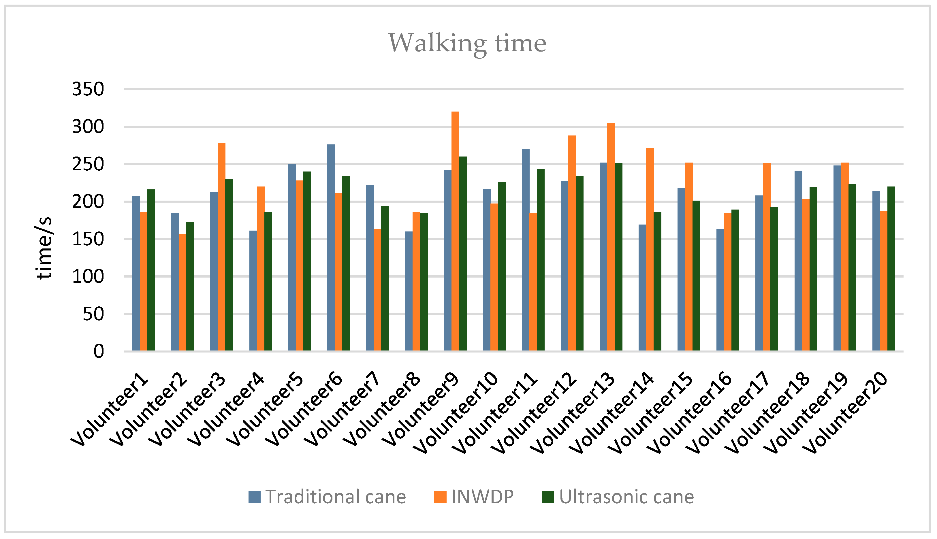
Data Analysis: The observed walking time results are shown in
Figure 13. The average walking times recorded were 217.1 s for traditional guide sticks, 226.2 s for the INWDP, and 215 s for ultrasonic canes. The experimental data indicated that the walking speed of the INWDP was comparable to that of traditional canes, differing by only 4%. However, significant individual variability was observed in the usage of the INWDP, attributed to the learning curve associated with adopting new technology, while traditional canes provided a more intuitive experience. Regarding collision counts, the INWDP effectively avoided collisions with airborne obstacles, while traditional guide sticks excelled in detecting low-level obstacles but failed to sense higher ones.
The experimental collision results are summarized in
Table 4. Overall, the INWDP excelled in obstacle avoidance, outperforming ultrasonic canes, while traditional canes were the least effective, particularly with mid-air obstacles. For obstacle recognition, the INWDP effectively communicated information about the obstacles ahead. In contrast, ultrasonic canes detected obstacles but could not differentiate between various kinds, and traditional canes provided neither advanced detection nor categorization of obstacles.
Interview Analysis: The test volunteers’ feedback on the INWDP, traditional white cane, and ultrasonic guide cane in this study mainly focused on three aspects:
Sense of Security and Environmental Cognition: Participants reported that the INWDP significantly enhanced their sense of security and awareness of their surroundings. By employing a voice broadcast function, the INWDP aids users in recognizing environmental cues, which helps alleviate anxiety and bolster confidence during travel. This aligns with findings discussed in the
Section 2, which emphasizes the significance of emotion-driven design strategies in mobility aids and other assistive technologies, stressing the importance of reducing feelings of anxiety and promoting self-assurance among individuals with disabilities.
Interactive Experience: The INWDP provided a superior user experience compared to traditional aids such as white canes. As noted in the
Section 2, similar design improvements in wheelchairs illustrate how advanced mobility devices can decrease hand fatigue and mitigate social awkwardness, such as inadvertently making contact with pedestrians. The device encourages a more interactive and exploratory engagement with the environment, offering a gratifying experience similar to how personalized prosthetic limbs enhance user confidence through an innovative design.
Appearance and Psychological Acceptance: As evidenced in the
Section 2, the prototype’s esthetics, which do not include the stick that represents disability, reflect emotion-driven design strategies comparable to those employed in wheelchairs and the stylish Phonak Sky series of hearing aids. This approach reduces the visibility of visual impairment, which helps lessen psychological burdens and enhances users’ readiness to adopt and use the device. Similarly to crutches designed to resemble umbrellas, the INWDP transforms into a standard assistive tool, effectively reducing the impact of disability labeling.
6. Limitation
While this study primarily focused on visually impaired individuals, the actual tests employed an alternative methodology that involved blindfolded participants to simulate the experiences of visually impaired users. This approach was adopted for several key reasons: during the preparation phase of the experiment, it became clear that conducting tests and interviews with 20 visually impaired participants presented unique challenges. Issues such as the logistical management of multiple participants, the safety risks associated with their travel to and from the test site, and the need to maintain adherence to the project timeline ultimately led the research team to recruit non-disabled individuals as substitutes for simulation testing.
To improve the scientific rigor and reliability of this study’s findings, a comprehensive literature review was conducted, which compared and analyzed relevant research on assistive technologies for people with disabilities. This review supported the study’s overarching goals. The design concept adopted an inclusive approach, highlighting esthetic aspects that follow the principle of “reducing the disability identity label,” as noted in the existing literature. Such design strategies have significantly boosted acceptance and willingness among people with disabilities to use assistive devices, justifying this study’s purpose. Furthermore, using volunteers with normal vision to simulate the visual impairment status cannot fully replicate the feelings of visually impaired people. However, the current study provides valuable interaction data and iteration direction for phased prototype testing. Future studies will aim to collaborate with disability organizations to involve actual visually impaired individuals during testing phases, refining both functionality and user experience based on direct feedback from real users.
Furthermore, the experimental data were collected in indoor settings, where the obstacles presented were everyday items, including static objects such as chairs, bicycles, potted plants, and prompt signs, along with low-speed moving pedestrians. The setup allowed for effective obstacle avoidance under these conditions. From the perspective of vibration-based obstacle avoidance, the intelligent navigation wearable device demonstrated the ability to detect various obstacles. However, the accurate categorization of obstacles necessitates the prior collection of images and subsequent training using the YOLO network, which means that not all obstacle types can be represented in the tests. Due to constraints related to time and resources, the dataset for this study was limited to seven common obstacles typically found on pedestrian pathways, restricting the device’s ability to identify a broader range of obstacles. Future research will focus on expanding the scope of obstacle identification in diverse scenarios to facilitate the recognition of additional obstacle categories.

