1. Introduction
Given increasing military demands, stealth technology has rapidly developed. Although considerable efforts have been devoted to low radar cross section (RCS) antenna designs, maintaining RCS reduction (RCSR) over broad-angle range continues to pose challenges [
1].
Many methods of RCSR of the antenna, such as shape modification [
2,
3], radar absorbing material (RAM) loading [
4,
5], the use of frequency selective surface (FSS) [
6], metasurfaces [
7,
8,
9] and RCSR using characteristic mode analysis (CMA) [
10,
11,
12,
13,
14] have been widely investigated. In [
2], it presents a geometrical shaping method to realize RCSR. The novel antenna can realize RCSR for co-polarization and cross-polarization simultaneously from 2.5 GHz to 8 GHz under normal incident plane wave. In [
4], it applies metamaterial absorber to waveguide slot antenna to reduce its RCS. The RCS of proposed antenna is reduced from 5.6 GHz to 5.87 GHz under normal incident wave without degradation of antenna performance. In [
9], it presents a polarization conversion metasurface and used as the radiator of the proposed CP antenna. It can realize RCS reduction over the bandwidth of 5.0 GHz–10.0 GHz under the normal incident wave. In [
10], it proposes a patch antenna by modification and loading to realize RCSR based on CMA. It can reduce RCS from 1.8 GHz to 4.0 GHz for cross-polarization under the normal incident wave. The aforementioned research works focus on the normal incident plane wave, which are not suitable for broad-angle RCSR design. In [
6], it proposes a FSS structure applied to the antenna to realize RCSR. It achieves RCSR at 4.1 GHz over a broad-angle range for dual-polarization. The design is lack-of-guidance and for only single frequency point. In [
13], it proposes a shape modification and parasitic patch loading method based on CMA to realize RCSR for dual-polarization from −30° to 30° over the frequency band of 2.3 GHz–2.5 GHz. In [
14], it presents a shape modification method with CMA, which can realize RCSR for co-polarization from −30° to 30° over the frequency band of 7.0 GHz–14.0 GHz. However, the RCSR angle range of these two designs is limited. Therefore, a new antenna design needs to be studied for broad-angle RCSR under dual-polarization incident plane waves.
In this paper, the common significant scattering modes at the interested angles in broad-angle range are selected based on the modal amplitude. By comparing the radiation modal currents and scattering modal currents, a shape modification design is proposed to cut off the scattering modal currents on the radiation patch and the ground to achieve broad-angle RCSR for dual-polarization. Then, a FSS structure is used to fill in the ground modification areas to maintain good radiation and scattering performance. Finally, a broad-angle low-RCS aperture-coupled microstrip antenna is realized for dual-polarization; meanwhile, its transmission and radiation performance keeps well. The measured and simulated results are in good agreement, which validates the design. This paper provides a new design solution for the broad-angle low-RCS antenna for dual-polarization.
Key contributions of this paper are as follows.
- (1)
A broad-angle low-RCS antenna design for dual-polarization using CMA is proposed.
- (2)
A broad-angle low-RCS aperture-coupled microstrip antenna for dual-polarization is obtained from 0° to 90°.
2. Theoretical Analysis
The RCS of the scattering object is calculated by the following equation [
15]:
where the
represents the RCS, R is the distance between the scattering object and radar,
is the scattering field,
is the incident field.
According to the characteristic mode theory [
16], the scattering field on the surface of any electromagnetic objects can be decomposed into a superposition of a series of orthogonal complete modes:
where the
is the total scattering field, in which
is the incident direction of the incident field and
is the scattering direction of the scattering field.
is the modal weighting coefficients (MWC) of the
nth scattering mode.
is the scattering field of the nth scattering mode.
is the tangential component of the incident electric-field at the antenna surface.
is the current of the
nth scattering mode.
is the eigenvalue of the nth scattering mode.
is the magnetic vector potential of the
nth scattering mode.
Equation (2) can also be written as follows:
where the
and
are the modal amplitude and phase, respectively,
where
and
are the phase of
and
, respectively.
It can be seen that is only the response function of the excitation source, which is related to the incident direction . is the amplitude product of the MWC and the modal far-field, which is a function of the incident direction and the scattering direction , simultaneously. Therefore, the selection criterion of important scattering modes for the arbitrary-angle incident plane wave is based on the modal amplitude instead of the |MWC|.
3. Design of Broad-Angle Low-RCS Microstrip Antenna for Dual-Polarization Based on CMA
In this section, shape modification is used to realize broad-angle RCSR for dual-polarization based on CMA. Firstly, the modal amplitude of the important scattering modes is reduced by the shape modification technology. Through reshaping the rectangular patch into a circular patch and removing parts of the ground, the scattering modal currents of the important scattering modes in broad-angle range can be successfully cut off. Therefore, the broad-angle RCSR is obtained for dual-polarization. Next, the FSS structure is designed to fill in the ground modification areas to maintain good radiation and scattering performance. In the operating band of the antenna, the FSS exhibits metal-like reflective properties. In the scattering band, it demonstrates air-like transmission characteristics. With these techniques, a broad-angle low-scattering microstrip antenna is achieved for dual-polarization without radiation performance deterioration.
3.1. Radiation Characteristic Analysis
Microstrip patch antenna is widely used in the military and civil fields because of its low profile, light weight, compact structure, and easy fabrication [
17]. An aperture-coupled microstrip antenna is chosen as the reference antenna [
18]. Its configuration is shown in
Figure 1, which shows the exploded, top, cutaway, bottom and side views. The antenna is consisting of two substrate layers: an upper dielectric substrate with a rectangular patch printed on the top, and a lower dielectric substrate with a slot-ground-plane placed on the top and a feed-line printed on the bottom, respectively. A dielectric substrate Taconic TLX(tm) with a relative permittivity of 2.55, a loss tangent of 0.0019, and a thickness of 2 mm is used for these two substrate layers. Its parameters are shown in
Table 1. As shown in
Figure 1, W1 and L1 are the width and length of the antenna, respectively. W2 and L2 are the width and length of the radiation patch. W3 and L3 are the width and length of the coupled-slot. W4 and L4 are the width and length of the feed-line. H is the thickness of the substrate.
Firstly, the reflection coefficient and radiation modes analysis of the aperture-coupled microstrip antenna are carried out. As shown in
Figure 2, the −10 dB reflection coefficient bandwidth of the antenna is 2.79–2.87 GHz, and the polarization direction of the antenna is parallel to the
x-axis.
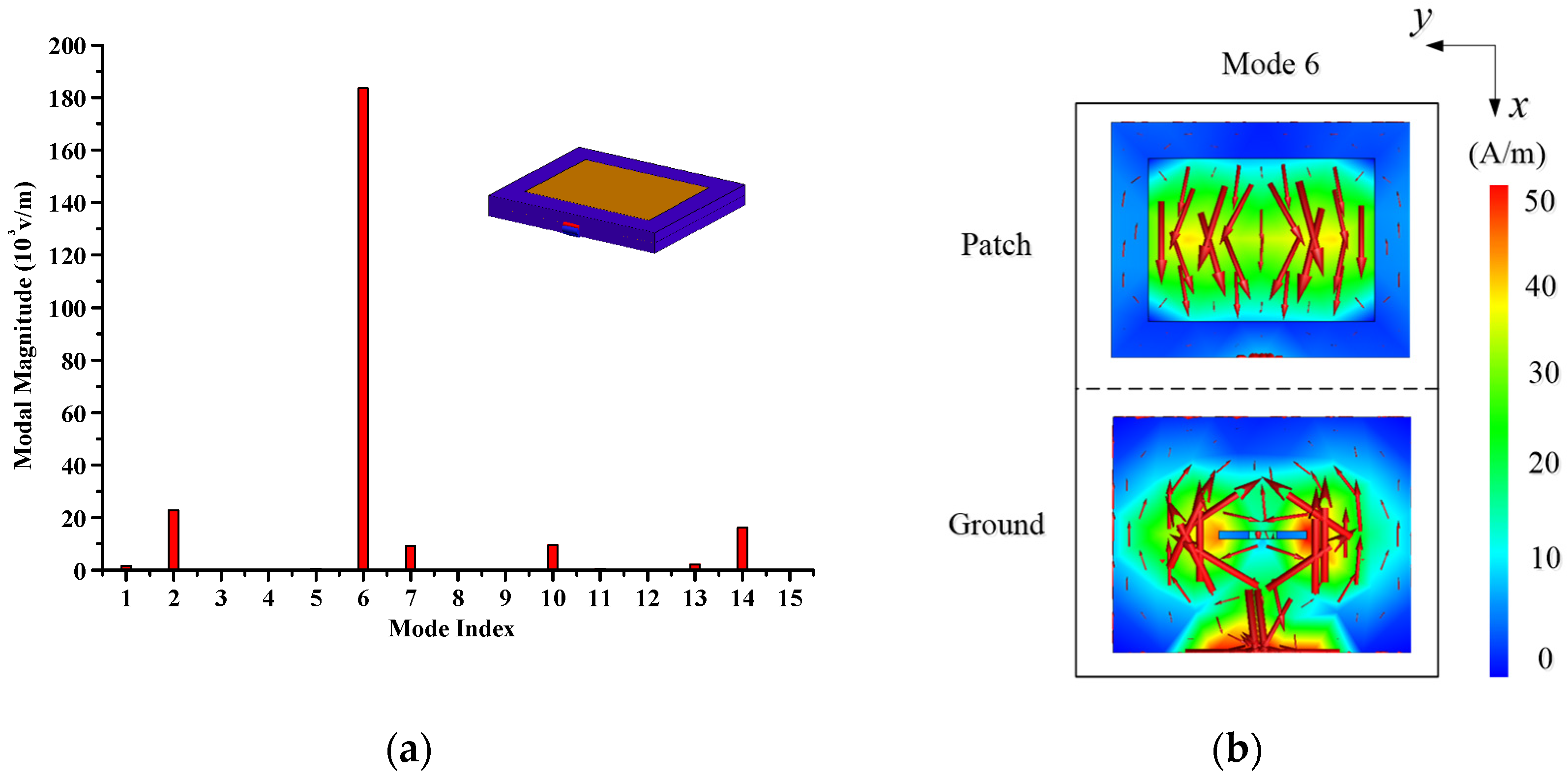
The radiation modal amplitudes of the first fifteen modes of the reference antenna are calculated using the commercial software FEKO 2021 and plotted in
Figure 3a, which shows that the radiation modal amplitude of mode 6 is the biggest. So, the mode 6 is the important radiation mode. The modal currents distribution of mode 6 is shown in
Figure 3b. The red arrows represent the current direction and intensity. It can be seen that the currents flow along the
x-axis on the patch and ground plane. In the following RCSR design, it should be protected from destruction to ensure the antenna works well.
3.2. Scattering Characteristic Analysis
In this section, there are two steps to complete the design of a broad-angle low-scattering antenna for dual-polarization. Firstly, the rectangular patch is modified into a circular patch and some parts of the ground are removed to achieve RCSR for dual-polarization ranging from 0° to 90°. Secondly, a FSS structure is used to fill in the removed part of the ground to maintain the radiation and scattering performance. Finally, a broad-angle RCSR design is realized for both co- and cross-polarizations.
Under the broad-angle incident plane wave excitation (
θ = 0°~90°,
φ = 0° and
φ = 90°, f = 6 GHz), the RCS of reference antenna is calculated for dual-polarization, as shown in
Figure 4. For the co-polarization, the monostatic RCS has the maximum value at
θ = 0°. As the incident angle
θ increases, the RCS decreases slowly. For the cross-polarization, it can be seen that the maximum value is at
θ = 0° and the second peak value is at
θ = 40°.
To achieve broad-angle RCSR from 0° to 90°, the scattering modal analysis are performed at
θ = 0°, 20°, 40°, 60° and 80°. According to the selection criterion of important scattering modes in
Section 2, the modal amplitudes of the reference antenna for dual-polarization are calculated at the above incident angles at 6.0 GHz, as shown in
Figure 5 and
Figure 6. The z-axis represents the modal amplitude, the x-axis represents the angle, and the y-axis represents the mode index.
For co-polarization, the modal amplitudes of the scattering mode 3 and mode 9 are larger than ones of the other modes at θ = 0°, 20°, 40°, 60° and 80° in
Figure 5a. Hence, the scattering mode 3 and mode 9 are the important scattering modes over the broad-angle range of 0~90°. Then, the modal currents of these two modes are calculated to guide the RCSR design. Their current distributions are displayed in
Figure 5b. The red arrows represent the current direction and intensity. As can be seen, the modal current of mode 9 is similar to the radiation modal currents, so this mode cannot disrupt for keeping radiation performance. The modal current of mode 3 on the radiation patch is mostly distributed on the four corners.
For cross-polarization, the modal amplitudes of the scattering mode 1 and mode 2 are larger than ones of the other modes at θ = 0°, 20°, 40°, 60° and 80° in
Figure 6a. Hence, mode 1 and 2 are the two important scattering modes over the broad-angle range of 0°~90°. Then, the modal currents of these two modes are calculated to guide the RCSR design. Their current distributions are displayed in
Figure 6b. The red arrows represent the current direction and intensity. As can be seen, the modal currents of mode 1 and mode 2 on the radiation patch are also mostly distributed on the four corners, which is same as that of the mode 3 for co-polarization. As for the ground, the intense scattering modal currents distributes at the four corners and the two short edges of the ground.
3.3. Broad-Angle and Dual-Polarizaton RCSR Design
According to the distribution of important scattering modal currents mentioned in the previous section, the radiation patch is reshaped into a circular patch and the four corners and two short edges of the ground are cut off to decrease the scattering modal currents of the important scattering modes for dual-polarization. Finally, the modified antenna is shown in
Figure 7.
The broad-angle RCS curves for dual-polarization are calculated and plotted in
Figure 8. As can be seen in
Figure 8a, the modified antenna can realize RCSR over the broad-angle range of 0° to 90° for co-polarization, and the peak RCSR value is 36 dB at 35° and the average RCSR value is 13 dB. As can be seen in
Figure 8b, the modified antenna can realize RCSR over the broad-angle range of 0° to 18° and 22° to 90° for cross-polarization, and the peak RCSR value is 10 dB at 45° and the average RCSR value is 5.1 dB. However, the reshaped ground causes the destruction of the radiation performance. So, a FSS structure is designed and applied to fill in the removed part of the ground.
In the operating band of the antenna, the FSS exhibits metal-like reflective properties, and in the scattering band, it demonstrates air-like transmission characteristics. The physical structure of the FSS unit is shown in
Figure 9. The FSS unit is composed of two substrate layers and one metallic layer. The two substrate layers are placed on the top and the bottom of the metallic layer, which broaden the passing band of the FSS unit. The symmetrical structure of the metallic layer ensures the insensitivity for the polarization, which means the FSS unit has the same transmission characteristics for the co-polarization and cross-polarization. As is shown in
Figure 10, the reflection coefficient curves show that the FSS behaves like a PEC ground to reflect electromagnetic waves from 2.79 GHz to 2.87 GHz and transmits electromagnetic waves like air from 5.0 GHz to 7.5 GHz. As is shown in
Figure 11, the broad-angle reflection coefficient curves represents that the FSS possesses a stable angle characteristic. Over the broad-angle 0° to 70°, the S
11 is about 0 dB at 2.83 GHz and is ranging from −47 dB to −15 dB at 6.75 GHz. It means that the FSS unit can keep its transmission characteristics over the broad angle range. Finally, the FSS structure is filled in the removed areas of the ground to form the proposed antenna, as shown in
Figure 12.
The scattering modal amplitudes of the proposed antenna for co-polarization and cross-polarization at 6 GHz are calculated and plotted in
Figure 13. Compared with the reference antenna, the important scattering modes for co-polarization have changed from mode 3 and 9 to mode 1 and 2. For cross-polarization, the important scattering modes have not changed and remain mode 1 and 2. Then, the modal currents of mode 1 and mode 2 are calculated and shown in
Figure 14. The red arrows represent the current direction and intensity. The currents of mode 1 on the patch mainly flow along the y-axis. The currents of mode 2 on the patch mainly flow along the x-axis. The currents intensity on the ground is relatively low. In comparison with the modal current of reference antenna, the modal current intensity exhibits a noticeable decrease.
Furthermore, the comparison of important modal amplitudes between the reference antenna and proposed antenna at 6 GHz are plotted in
Figure 15 and
Figure 16. As is shown in
Figure 15, after reshaping and FSS-loading, the important scattering mode 3 and 9 of the reference antenna are converted to mode 1 and 2, and their amplitudes are significantly reduced for co-polarization. It can be concluded that RCSR from 0° to 90° can be obtained. As is shown in
Figure 16, the modal amplitude of mode 2 is reduced to almost zero over the broad-angle range from 0° to 90°, and the modal amplitude of mode 1 is also reduced significantly except for the angle range from 0° to 20°. It can be concluded that RCSR from 30° to 90° can be obtained. From 0° to 20°, the modal amplitude of proposed mode 1 increases evidently, which results in the RCS increase in the proposed antenna from 18° to 22°.
4. Test and Discussion
The reference and proposed antenna prototypes are fabricated and tested, as shown in
Figure 17. The radiation and scattering pattern measurements are performed in the anechoic chamber, as shown in
Figure 18. The comparison of monostatic RCS over the broad-angle between the reference antenna and the proposed antenna at 6 GHz is shown in
Figure 19. The proposed antenna achieves 9.0 dB average and 17 dB peak RCSRs under co-polarization incident plane wave (
θ-polarized,
φ = 0°) and 5.0 dB average and 20 dB peak RCSRs under cross-polarization incident plane wave (
θ-polarized,
φ = 90°), respectively. Measured and simulated results are in good agreement to verify the design. The only significant difference is about 10 dB at θ = 74° for cross-polarization. However, the calculated RCS at θ = 74° for cross-polarization is very low, about -58dBsm, so it is difficult for test. Regarding the 18°~22° RCSR gap for cross-polarization, it is caused by the increase in the amplitude of mode 1 in
Figure 16a. The RCSR frequency band is from 5.6 GHz to 6.2 GHz for dual-polarization. With the limitation of space, the RCS simulated results from 5.6 GHz to 6.2 GHz for proposed and reference antenna are shown in
Supplementary Materials.
The simulated and measured reflection coefficient curves are plotted in
Figure 20. As can be seen, the bandwidth of the proposed antenna is basically same as that of the reference antenna, and the antenna works from 2.79 GHz to 2.87 GHz (2.82%). The simulated and measured radiation patterns at 2.84 GHz are shown in
Figure 21, and the gain is about 6 dBi at 2.84 GHz. The radiation patterns are consistent. Generally speaking, the radiation characteristics remain unchanged.
The comparison of the main performance among the previously reported antennas and this work is shown in
Table 2. The methods of RCSR based on CMA are listed. For antenna size, the whole size of the proposed antenna in this work is smaller than those of the previous works. For the RCSR angular range, the proposed antenna can realize low-RCS from −90°to 90°, which is broader than those of the previous works. For the polarization property, these antennas in this work and Refs. [
12,
13] can realize RCSR for dual-polarization, and the antennas in Refs. [
10,
11,
13] can only realize RCSR for co-polarization or cross-polarization. For the radiation performance, the gain of the proposed antenna is not influenced, while the antenna gain in Refs. [
10,
11,
12] presents the decline of a varying degree. In conclusion, the proposed antenna exhibits obvious advantages in radiation and scattering performance compared with the previous works.
5. Conclusions
In this paper, a design of broad-angle low-scattering microstrip antenna for dual-polarization is proposed. With shape modification of the radiation patch and ground based on the CMA, a broad-angle RCSR for the dual-polarization is realized. Furthermore, a FSS structure is introduced to fill in the ground modification areas to maintain the radiation and scattering performance. Finally, the proposed antenna keeps the transmission and radiation performance well.
The measured results show that compared to the reference antenna, the proposed antenna achieves RCSR from 0°to 90°, and the average and peak RCSRs are 9.0 dB and 17 dB, respectively, for the co-polarization. For the cross-polarization, it can realize low-RCS from 0° to 18° and 22° to 90°, and the average and peak reductions 5.0 dB and 20 dB, respectively; in other angle range, the RCS is relatively low, though not reduced. Additionally, due to the symmetrical structure of the antenna, low-RCS can be achieved within an angular range of −90° to 90°. Measured and simulated results are in good agreement to verify the design, which provides a feasible way to reduce the broad-angle RCS of antenna for dual-polarization.
The broad-angle dual-polarization low RCS microstrip antenna can be used as an element of broad-angle dual-polarization low RCS array antenna. This design method is suitable for RCSR design of other types of antenna.
Supplementary Materials
The following supporting information can be downloaded at:
https://www.mdpi.com/article/10.3390/electronics14112121/s1, Figure S1. Simulated RCS curves of the reference antenna and proposed antenna for co-polarization from 5.0 GHz to 7.0 GHz. (
a)
θ = 0° (
b)
θ = 20° (
c)
θ = 40° (
d)
θ = 60° (
e)
θ = 80°. Figure S2. Simulated RCS curves of the reference antenna and proposed antenna for cross-polarization from 5.0 GHz to 7.0 GHz. (
a)
θ = 0° (
b)
θ = 20° (
c)
θ = 40° (
d)
θ = 60° (
e)
θ = 80°.
Author Contributions
Conceived and designed the experiments, Y.L.; method guidance, writing—review and supervision, B.D.; funding acquisition, D.J. All authors have read and agreed to the published version of the manuscript.
Funding
This research received no external funding.
Data Availability Statement
The data used to support the findings of this study are included within the article.
Conflicts of Interest
Author Yakun Liu, Biao Du and Dan Jia were employed by the company The 54th Research Institute of China Electronics Technology Group Corporation. They declare that the research was conducted in the absence of any commercial or financial relationships that could be construed as a potential conflict of interest.
Abbreviations
| CMA | characteristic mode analysis |
| RCS | radar cross section |
| RCSR | radar cross section reduction |
| FSS | frequency selective surface |
| RAM | radar absorbing material |
| MWC | modal weighting coefficient |
| PEC | perfect electric conductor |
| CMC | characteristic modes cancelation |
References
- Zheng, Q.; Zhao, Q.; Qu, Y.; Yang, X.; Pang, X. Wideband and Wide-Angle RCS Reduction of MIMO Antennas Using Compensate-Layered Metasurface for Cube Satellite Applications. IEEE Trans. Antennas Propag. 2024, 72, 6491–6499. [Google Scholar] [CrossRef]
- Jiang, W.; Liu, Y.; Gong, S.; Hong, T. Application of bionics in antenna radar cross section reduction. IEEE Antennas Wirel. Propag. Lett. 2009, 8, 1275–1278. [Google Scholar] [CrossRef]
- Dikmen, C.M.; Çimen, S.; Çakir, G. Planar octagonal-shaped UWB antenna with reduced radar cross section. IEEE Trans. Antennas Propag. 2014, 62, 2946–2953. [Google Scholar] [CrossRef]
- Liu, T.; Cao, X.; Gao, J.; Zheng, Q.; Li, W.; Yang, H. RCS reduction of waveguide slot antenna with metamaterial absorber. IEEE Trans. Antennas Propag. 2013, 61, 1479–1484. [Google Scholar] [CrossRef]
- Liu, Y.; Zhao, X. Perfect absorber metamaterial for designing low-RCS patch antenna. IEEE Antennas Wirel. Propag. Lett. 2014, 13, 1473–1476. [Google Scholar] [CrossRef]
- Liu, Y.; Hao, Y.; Wang, H.; Li, K.; Gong, S. Low RCS Microstrip Patch Antenna Using Frequency-Selective Surface and Microstrip Resonator. IEEE Antennas Wirel. Propga. Lett. 2015, 14, 1290–1293. [Google Scholar] [CrossRef]
- Zheng, Y.; Gao, J.; Cao, X.; Yuan, Z.; Yang, H. Wideband RCS reduction of a microstrip antenna using artificial magnetic con-ductor structures. IEEE Antennas Wirel. Propag. Lett. 2015, 14, 1582–1585. [Google Scholar] [CrossRef]
- Jia, Y.; Liu, Y.; Gong, S.; Zhang, W.; Liao, G. A low-RCS and high-gain circularly polarized antenna with a low profile. IEEE Antennas Wirel. Propag. Lett. 2017, 16, 2477–2480. [Google Scholar] [CrossRef]
- Azizi, Y.; Soleimani, M.; Sedighy, S.H.; Matekovits, L. Low-Cost, Low-Profile Wide-Band Radar Cross Section Reduction Using Dual-Concentric Phase Gradient Modulated Surface. Electronics 2021, 10, 1552. [Google Scholar] [CrossRef]
- Zhao, J.; Chen, Y.; Yang, S. In-Band Radar Cross-Section Reduction of Slot Antenna Using Characteristic Modes. IEEE Antennas Wirel. Propag. Lett. 2018, 17, 1166–1170. [Google Scholar] [CrossRef]
- Liu, Y.; Du, B.; Jia, D. Ultra-wide band radar cross section reduction for ring-shaped microstrip antenna based on characteristic mode analysis. Microw. Opt. Technol. Lett. 2021, 63, 1538–1546. [Google Scholar] [CrossRef]
- Han, J.; Jia, D.; Du, B.; Han, G. Design of Broadband Low-RCS Array Antennas Based on Characteristic Mode Cancellation. Electronics 2023, 12, 1536. [Google Scholar] [CrossRef]
- Shi, G.; Jia, Y.; Liu, Y. Theoretic Study of Antenna Scattering Problems Based on Characteristic Modes and Its Application in Reducing Antenna Scattering. IEEE Trans. Antennas Propag. 2023, 71, 2098–2109. [Google Scholar] [CrossRef]
- Jia, Y.; Luo, J.; Ren, X.; Shi, G.; Liu, Y. Design of Low-RCS Vivaldi Antenna Based on Characteristic Mode Analysis. IEEE Antennas Wirel. Propag. Lett. 2024, 23, 1246–1250. [Google Scholar] [CrossRef]
- Ruck, G.T.; Barrick, D.E.; Stuart, W.D.; Krichbaum, C.K. Radar Cross Section Handbook; Springer: Berlin/Heidelberg, Germany, 1970. [Google Scholar]
- Chen, Y.; Wang, C. Characteristic Modes: Theory and Applications in Antenna Engineering; Wiley: New York, NY, USA, 2015. [Google Scholar]
- James, J.R.; Hall, P.S. (Eds.) Handbook of Microstrip Antennas; Peter Peregrinus: London, UK, 1989. [Google Scholar]
- Gong, S.; Liu, Y. Antenna radar cross section analysis. In Prediction and Reduction of Antenna Radar Cross Section, 1st ed.; Xidian University Press: Xi’an, China, 2010; pp. 84–88. (In Chinese) [Google Scholar]
Figure 1.
Configuration of the reference antenna. (a) Exploded view, (b) Top, cutaway, bottom and side views.
Figure 1.
Configuration of the reference antenna. (a) Exploded view, (b) Top, cutaway, bottom and side views.
Figure 2.
Simulated reflection coefficient curve of the reference antenna.
Figure 2.
Simulated reflection coefficient curve of the reference antenna.
Figure 3.
Radiation modal analysis results of the reference antenna at 2.84 GHz. (a) Modal Amplitude, (b) Modal currents.
Figure 3.
Radiation modal analysis results of the reference antenna at 2.84 GHz. (a) Modal Amplitude, (b) Modal currents.
Figure 4.
Simulated RCS results of the reference antenna. (a) Co-polarization (φ = 0°), (b) Cross-polarization (φ = 90°).
Figure 4.
Simulated RCS results of the reference antenna. (a) Co-polarization (φ = 0°), (b) Cross-polarization (φ = 90°).
Figure 5.
Scattering modal analysis results of the reference antenna for co-polarization at 6.0 GHz. (a) Modal amplitudes at different angles, (b) Modal currents.
Figure 5.
Scattering modal analysis results of the reference antenna for co-polarization at 6.0 GHz. (a) Modal amplitudes at different angles, (b) Modal currents.
Figure 6.
Scattering modal analysis results of the reference antenna for cross-polarization at 6.0 GHz. (a) Modal amplitudes at different angles, (b) Modal currents.
Figure 6.
Scattering modal analysis results of the reference antenna for cross-polarization at 6.0 GHz. (a) Modal amplitudes at different angles, (b) Modal currents.
Figure 7.
Configuration of the reshaped antenna. (a) Patch, (b) Ground.
Figure 7.
Configuration of the reshaped antenna. (a) Patch, (b) Ground.
Figure 8.
Simulated RCS results of the reference antenna and modified antenna. (a) Co-polarization, (b) Cross-polarization.
Figure 8.
Simulated RCS results of the reference antenna and modified antenna. (a) Co-polarization, (b) Cross-polarization.
Figure 9.
Configuration of the FSS unit.
Figure 9.
Configuration of the FSS unit.
Figure 10.
Simulated reflection coefficient curves of the FSS unit.
Figure 10.
Simulated reflection coefficient curves of the FSS unit.
Figure 11.
Simulated broad-angle reflection coefficient curves of the FSS unit.
Figure 11.
Simulated broad-angle reflection coefficient curves of the FSS unit.
Figure 12.
Configuration of the proposed antenna.
Figure 12.
Configuration of the proposed antenna.
Figure 13.
Modal amplitudes of the proposed antenna at different angles at 6.0 GHz. (a) Co-polarization, (b) Cross-polarization.
Figure 13.
Modal amplitudes of the proposed antenna at different angles at 6.0 GHz. (a) Co-polarization, (b) Cross-polarization.
Figure 14.
Modal currents of mode 1 and mode 2 for the proposed antenna.
Figure 14.
Modal currents of mode 1 and mode 2 for the proposed antenna.
Figure 15.
Comparison of important scattering modal amplitudes between reference antenna and proposed antenna at different angles for the co-polarization at 6.0 GHz. (a) Mode 1. (b) Mode 2.
Figure 15.
Comparison of important scattering modal amplitudes between reference antenna and proposed antenna at different angles for the co-polarization at 6.0 GHz. (a) Mode 1. (b) Mode 2.
Figure 16.
Comparison of important scattering modal amplitudes between reference antenna and proposed antenna at different angles for the cross-polarization at 6.0 GHz. (a) Mode 1. (b) Mode 2.
Figure 16.
Comparison of important scattering modal amplitudes between reference antenna and proposed antenna at different angles for the cross-polarization at 6.0 GHz. (a) Mode 1. (b) Mode 2.
Figure 17.
Fabricated antenna prototypes. (a) Proposed antenna, (b) Reference antenna.
Figure 17.
Fabricated antenna prototypes. (a) Proposed antenna, (b) Reference antenna.
Figure 18.
Fabricated antennas and measurement system.
Figure 18.
Fabricated antennas and measurement system.
Figure 19.
Simulated and measured RCS curves of the reference antenna and proposed antenna for dual-polarization at 6GHz. (a) Co-polarization (φ = 0°), (b) Cross-polarization (φ = 90°).
Figure 19.
Simulated and measured RCS curves of the reference antenna and proposed antenna for dual-polarization at 6GHz. (a) Co-polarization (φ = 0°), (b) Cross-polarization (φ = 90°).
Figure 20.
Simulated and measured reflection coefficient curves of the reference antenna and proposed antenna.
Figure 20.
Simulated and measured reflection coefficient curves of the reference antenna and proposed antenna.
Figure 21.
Simulated and measured radiation patterns at 2.84 GHz. (a) φ = 0°, (b) φ = 90°.
Figure 21.
Simulated and measured radiation patterns at 2.84 GHz. (a) φ = 0°, (b) φ = 90°.
Table 1.
Dimension parameters of the reference antenna.
Table 1.
Dimension parameters of the reference antenna.
| Parameters | Value/mm | Parameters | Value/mm |
|---|
| W1 | 40 | L1 | 49 |
| W2 | 27.6 | L2 | 37 |
| W3 | 1.4 | L3 | 14.3 |
| W4 | 4.5 | L4 | 33.5 |
| H | 2 | | |
Table 2.
Comparison of main performance among previously reported antennas and this work.
Table 2.
Comparison of main performance among previously reported antennas and this work.
| Ref. | Electrical Size
(λ0) | RCSR Angle Range
(°) | Polarization
Property | Gain Variation
(dB) | Method |
|---|
| [10] | 0.52 × 0.45 | 0 | cross | <0.5 | Modification and load using CMA |
| [11] | 0.60 × 0.60 | 0 | cross | −0.15 | Modification using CMA |
| [12] | 2.00 × 2.00 | 0 | co/cross | −0.5 | CMC using CMA |
| [13] | 0.63 × 0.63 | ±30 | co/cross | - | Modification and load parasitic patch using CMA |
| [14] | 1.60 × 0.80 | ±30 | co | - | Modification using CMA |
| This work | 0.38 × 0.46 | ±90 | co/cross | 0 | Modification using CMA/FSS |
| Disclaimer/Publisher’s Note: The statements, opinions and data contained in all publications are solely those of the individual author(s) and contributor(s) and not of MDPI and/or the editor(s). MDPI and/or the editor(s) disclaim responsibility for any injury to people or property resulting from any ideas, methods, instructions or products referred to in the content. |
© 2025 by the authors. Licensee MDPI, Basel, Switzerland. This article is an open access article distributed under the terms and conditions of the Creative Commons Attribution (CC BY) license (https://creativecommons.org/licenses/by/4.0/).


