Article

Online SSA-Based Real-Time Degradation Assessment for Inter-Turn Short Circuits in Permanent Magnet Traction Motors

1
College of Mechanical and Vehicle Engineering, Hunan University, Changsha 410082, China
2
CRRC Zhuzhou Electric Locomotive Institute Co., Ltd., Zhuzhou 412001, China
3
School of Automation, Central South University, Changsha 410083, China
*
Author to whom correspondence should be addressed.
Electronics 2025, 14(10), 2095; https://doi.org/10.3390/electronics14102095
Submission received: 26 March 2025 / Revised: 17 May 2025 / Accepted: 19 May 2025 / Published: 21 May 2025

Abstract

:
Inter-turn short circuits (ITSCs) in permanent magnet synchronous motors (PMSMs) pose significant risks due to their subtle early symptoms and rapid degradation. To address this, we propose an online real-time diagnostic method for assessing the degradation state. This method employs the Sparrow Search Algorithm (SSA) for the online real-time identification of fault characteristic parameters. Following an analysis of the fault mechanisms of inter-turn short circuits, a mathematical model has been developed to include the short-circuit turns ratio and insulation resistance. An evaluation index has also been developed to assess the degree of fault-related degradation. To address the strong nonlinearity of parameters in the fault model, the SSA is employed for the real-time joint identification of parameters that characterize the relationship between fault location and degradation degree. Simulation experiments demonstrate that the SSA achieves convergence within 40 iterations, with a relative error below 5% and absolute error less than 0.007, outperforming traditional algorithms like the PSO, a significant improvement in the early detection of degradation caused by inter-turn short circuits and a step forward in technical support ensuring greater reliability and safety for the traction systems used in rail transit.

1. Introduction

The traction drive system is the heart of rail transit rolling stock, and its performance and reliability directly impact the operational safety and energy efficiency of trains. Significant advantages in efficiency, power density, acceleration, and noise reduction have led to permanent-magnet synchronous motors (PMSMs) replacing traditional asynchronous motors and becoming the power unit of choice for the new generation of high-speed electric multiple units (EMUs), high-power AC transmission locomotives, and urban rail transit traction systems [1]. The widespread commercial application of permanent magnet synchronous motors has emerged as a critical focus for global innovation in rail transit technology driven in part by the national strategy for building strength in transportation and carbon peaking and neutrality goals. Be that as it may, the increasing complexity of operational environments and length of service lives have introduced new fault risks along with the permanent magnet synchronous motors, of which inter-turn short circuit faults are a significant cause for concern due to the difficulty of detecting them and the rapid degradation that can result.
Inter-turn short circuits are typically the result of damage to winding insulation, mechanical stress, or manufacturing defects. The initial indications of a fault are often subtle and easily masked by system noise. Failure to detect a fault in a timely manner can result in continuous current flow, exacerbating temperatures within the motor and increasing fluctuations in electromagnetic torque, creating abnormal vibrations and noise, reducing efficiency, and ending, in severe cases, with demagnetization or burnt windings. What is more, when the permanent magnet synchronous motor is idling, the magnetic flux linkage cuts through the stator windings and generates counter EMF, creating significant challenges for control and protection mechanisms during fault states. Consequently, a highly accurate diagnostic method capable of tracking fault-related degradation in real time would greatly improve operational safety and simplify maintenance.
Research conducted on the detection and diagnosis of inter-turn short circuits has progressed significantly in recent years, though many limitations must still be addressed. Arellano-Padilla et al. [2] achieved fault diagnosis by injecting high-frequency voltage into the motor winding and obtaining a spatial modulation profile online and comparing it with a pre-stored normal motor spatial modulation profile. Due to the energy conversion in the air gap magnetic field, when the stator has turn-to-turn short-circuit fault, the fault current in the short circuit branch will produce magnetomotive force, which will change the magnetic field around the short-circuit branch, including stray magnetic flux. Therefore, no matter the air gap magnetic field or the stray magnetic field, there is important information related to the health status of the motor. The abnormal magnetic flux can be detected by the magnetic flux measurement equipment, and then, the occurrence of the fault can be judged [3,4]. Irhoumah et al. [5] proposed the detection method of multi-angle detection coils installed on the motor surface and improved the detection accuracy through a data fusion algorithm. It is proved that the highest detection accuracy can be achieved when the detection coils are installed on the radial line where the fault winding is located. The above intrusive inter-turn short-circuit fault diagnosis methods often interfere with the system to some extent and even require shutdown. At the same time, some methods need to add additional fault detection equipment, which is not conducive to on-board implementation but also reduces the economy and reliability of the system. Urresty et al. [6] proposed to establish a fault indicator based on the fundamental component of zero sequence voltage, which realized the online detection of an inter-turn short-circuit fault under unstable conditions. Jeong et al. [7] proposed a fault indicator based on a negative-sequence voltage component. Compared with the method based on a zero-sequence component, the fault indicator can detect a weaker fault degree. In addition, it is proved that the amplitude of the fault current is proportional to the speed under weak fault. Kemmertmuller et al. [8] and Forstner et al. [9] analyzed the core magnetic saturation caused by turn-to-turn short circuit fault by establishing an equivalent magnetic circuit model and then verified the real-time performance and accuracy of the equivalent magnetic circuit model under health/fault conditions through experimental comparative analysis. The state observation method compares the actual output of the electric drive system with the output of the observer and then obtains the fault determination results. For this reason, Mazzoletti et al. [10] and Moon et al. [11] proposed a method based on the state observer to generate the current or voltage current residual vector and then used for the diagnosis of inter-turn short circuit. Guezmil et al. [12] proposed the method of using high-order sliding mode observers to improve the robustness of the diagnosis method. Because the inter-turn short circuit fault will cause changes in motor system parameters, the method based on parameter identification can also achieve fault diagnosis. Abdallah et al. [13] proposed a method based on rolling time domain estimation, which combines offline measurement data with online parameter estimation, identifies d-axis current based on high sampling frequency, and conducts real-time monitoring of stator turn-to-turn short circuit fault. The model-based diagnosis method has less calculation and is convenient for online fault detection, but some voltage-based methods need additional sensing equipment. In addition, this method is highly dependent on the model accuracy, but the changes in motor parameters caused by faults increase the difficulty of nonlinear modeling. In engineering applications, in order to avoid false alarm caused by noise and other factors, the fault determination threshold is often set to a higher value. Therefore, in the initial weak fault state, the output result of the fault model often makes it difficult to trigger the fault alarm. Therefore, most of the existing studies enhance the fault characteristics by setting the residual insulation to a state close to zero resistance. However, in fact, the initial residual insulation resistance value of interturn short circuit fault is relatively large, which is not consistent with the above implementation method, especially under the transient conditions of speed and load changes.
The signal-based fault diagnosis does not rely on the input and output model anymore. Because the abnormal condition of the motor will lead to the change of the motor’s operating state, the fault judgment conclusion can be drawn by extracting the fault information in the measured signal and comparing it with the prior knowledge in the healthy state during the motor’s operation. Kim et al. [14] proposed an inter-turn short circuit fault detection method based on fast Fourier transform to extract the second harmonic of q-axis current, which realized effective diagnosis under steady-state operation conditions. Alvarez Gonzalez et al. [15] processed the motor phase current signal with Hilbert Huang transform and then established a fault indicator based on the standard deviation of the obtained instantaneous frequency and instantaneous amplitude. Finally, by comparing with the threshold set in advance, the fault diagnosis of inter-turn short circuit is realized.
The long-term operation of electric drive systems under complex working conditions will generate a large amount of historical operating data, including motor current, speed, temperature, vibration, etc. These historical data record the operating status of the motor at different times and under different working conditions, reflecting the performance characteristics of the electric drive system and possible fault problems. By using data-driven diagnostic methods, it is possible to deeply explore the fault features hidden in these historical data, thereby achieving fault diagnosis. Lee et al. [16] used the attention LSTM network and used negative sequence and positive sequence current signals to evaluate the initial fault condition of inter-turn short circuit (the number of short circuit turns is 4.2~8.3%, and the residual insulation resistance is 0.21 Ω~2.1 Ω). Mohammad Alikhani et al. [17] utilized long short-term memory (LSTM) networks to identify dynamic fault modes, capturing the characteristics of fault timing sequences in an approach that performed poorly in real time and would be insufficient for the requirements of online monitoring. Fang et al. [18] applied transfer learning to the diagnosis of faults in small samples, reducing data dependence through the use of pre-trained models. The complexity of the training process, however, places practical limitations on deployment. Fadzail et al. [19] used stator current, torque, and speed signals as training-set data, trained the artificial neural network, and realized the classification of inter-turn short-circuit fault and open circuit fault. Shih et al. [20] converted the measured one-dimensional current data into a two-dimensional image as the input of the convolutional neural network (CNN) model. Finally, the classification of short-circuit faults with 5~15% different short-circuit turns and 0.1~0.5 ohm turn-to-turn residual insulation is realized. Song et al. [21] proposed a fault diagnosis model based on the CNN, able to automatically extract the features of current waveforms and classify with a high degree of accuracy. It is limited, however, by the substantial amount of annotated data required and exhibits limited capabilities for generalization.
In summary, existing methods are hindered by notable limitations in real-time performance, robustness, and practical applicability:
① The method based on signal analysis is insensitive to early minor faults and affected by fluctuations in working conditions. ② Traditional optimization algorithms converge slowly with strongly coupled nonlinear parameters and often become trapped in local optima. ③ Deep learning models require extensive annotated data and struggle with real-time performance on embedded platforms. ④ Multi-sensor fusion technology is costly and the difficulties of synchronizing complex data hinders large-scale application.
The Sparrow Search Algorithm (SSA) [22], introduced by Chinese scholar Zhang Haifeng and his team in 2020, is a novel swarm intelligence optimization algorithm that offers significant advantages for applications requiring robustness and multimodal optimization. It is against this backdrop that this paper would propose a method leveraging the strong global search capabilities and robustness of the SSA for the early detection of inter-turn short circuits in permanent magnet synchronous motors and the real-time assessment of the resulting degradation. This method employs the SSA to identify fault characteristic parameters online in real time. A fault coupling model encompassing the ratio of short-circuited turns (μ) and insulation resistance (Rf) is established, from which a quantitative index for the degree of fault-related degradation (μFI) is then designed. An SSA-driven fitness function has also been constructed for increased accuracy in the identification of parameters. The main contributions of this paper are as follows:
(1)
A method employing online identification to diagnose in real time the degradation resulting from inter-turn short circuits;
(2)
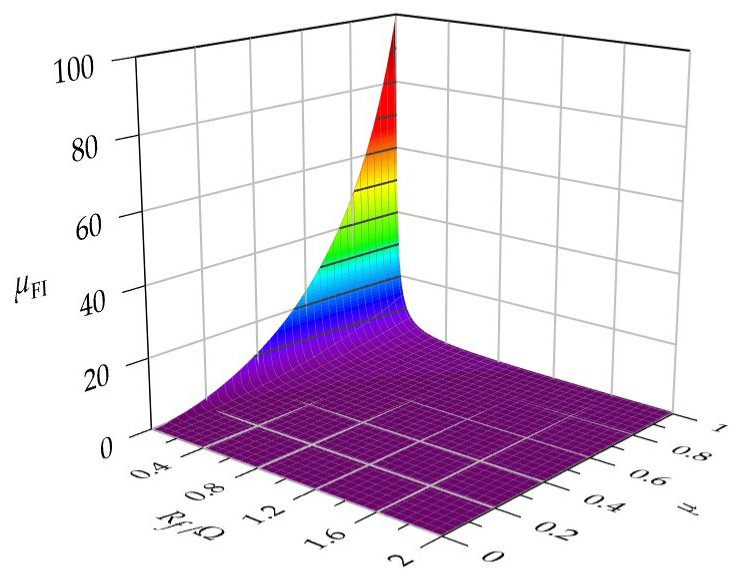
The revelation of an μ and Rf nonlinear coupling mechanism on the fault current and a proposal for a hierarchical early warning strategy based on μFI;
(3)
An online SSA optimization framework designed to achieve fast convergence and stable estimation of the identified parameters and, thus, address the shortcomings of traditional algorithms in identifying strong nonlinear parameters.
This paper has been organized in such a way that Section 2 provides an analysis of the fault mechanisms of inter-turn short circuits and a degradation state model, Section 3 presents an SSA-based algorithm for the real-time identification of fault parameters, Section 4 verifies the effectiveness of the algorithm through simulation experiments, and Section 5 provides a summary and outlook for future research.

2. Fault Analysis and Degradation Modeling for Inter-Turn Short Circuits in Permanent Magnet Synchronous Motors

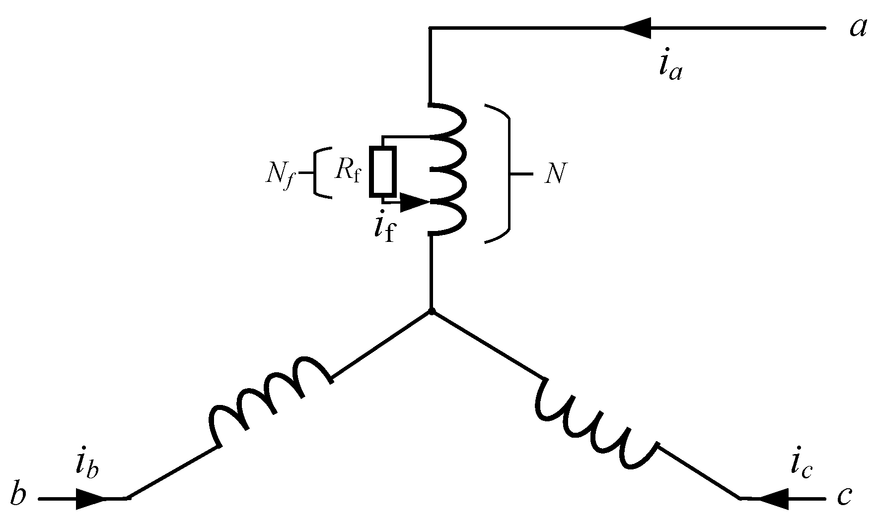
2.1. An Analysis of the Fault Mechanism of Inter-Turn Short Circuits

The main circuit of a typical permanent magnet traction system for a locomotive and EMU is shown in Figure 1a. It mainly consists of three parts: a traction transformer, a traction converter (including a charging circuit, a four-quadrant rectifier, a ground detection circuit, an DC link circuit, a traction inverter, etc.), and a permanent magnet traction motor. The physical drawings of the traction transformer, traction converter, and traction motor are shown in Figure 1b–d.
The equivalent structure of a permanent magnet synchronous motor with an inter-turn short circuit in the phase A winding is depicted in Figure 2 [4]. In the figure, the inter-turn short circuit cuts the phase A winding into two parts: a normal loop a1 and faulted loop a2. The fault current represents the current of the faulted loop. The severity of the inter-turn short circuit in a motor is generally expressed by the ratio of short-circuited turns μ and insulation resistance Rf, where μ represents the ratio of the number of short-circuited turns N f to the total number of turns N in the winding, i.e., μ = N f / N .
The mathematical model of a permanent magnet synchronous motor in dq-axis coordinates under normal circumstances is represented by Equation (1) [1]:
V d = R s i d + d d t ( L d i d ) ω e L q i q V q = R s i q + d d t ( L q i q ) ω e L d i d + ω e ψ m
where Rs is the stator winding resistance, Ld and Lq are the equivalent inductances of the winding in the d and q axes, respectively, ψ m represents the flux linkage of the permanent magnet, ud and uq are the stator voltages, id and iq are the stator currents, and ω e is the angular velocity of the motor.
When an inter-turn short circuit occurs in the stator winding, the mathematical model can be expressed as follows:
V d = R s i d + d d t L d i d ω e L q i q 2 3 μ L d d i f d t cos θ p S C · 2 π / 3 2 3 μ i f R s cos θ p S C · 2 π / 3 + ω e L q sin θ p S C · 2 π / 3 ω e L d sin θ p S C · 2 π / 3 V q = R s i q + d d t L q i q + ω e L d i d + ψ m + 2 3 μ L q d i f d t sin θ p S C · 2 π / 3 + 2 3 μ i f R s sin θ p S C · 2 π / 3 ω e L d cos θ p S C · 2 π / 3 + ω e L q cos θ p S C · 2 π / 3
where pSC of 0, 1, and −1 corresponds to the inter-turn short circuit in phase A, B, and C windings, respectively; θ is the electrical position angle of the permanent magnet motor rotor; and
i f = μ μ · ( 1 μ ) · R s + R f V d · cos θ p S C · 2 π / 3 V q · sin θ p S C · 2 π / 3

2.2. An Analysis of Inter-Turn Short-Circuit Fault Characteristics

From Figure 1 and Equation (3), it is evident that two key parameters affecting the severity of an inter-turn short circuit are the insulation resistance Rf and the ratio of short-circuited turns μ. Rf is inversely proportional to the magnitude of the fault current, directly reflecting the severity of the fault; thus, a small Rf typically results in a large fault current in the shorted circuit. Conversely, the ratio of short-circuited turns μ is directly proportional to the magnitude of the current, meaning that a large μ corresponds to a large fault current. Since these two parameters are independent of stator current, speed, and other operating conditions, they serve as ideal indicators of the severity of an inter-turn short circuit.
The fault current is influenced by both the insulation resistance Rf and the ratio of short-circuited turns μ and insufficient to assess fault severity with a single parameter. The fault quantitative evaluation index μFI, as shown in Equation (4), is defined to evaluate the severity of an inter-turn short circuit.
μ F I = μ 2 μ · ( 1 μ ) · R s + R f
From Equation (4), it is evident that in the absence of an inter-turn short circuit, μ = 0 and μFI = 0. As the severity of the fault increases—either by a decrease in Rf or an increase in μ—the μFI increases too. The variation of μFI with Rf and μ is illustrated in Figure 3. The conclusion to be drawn from Equation (4) and Figure 2 is that μFI is not in one-to-one correspondence with μ or Rf, i.e., the same μFI value may correspond to multiple combinations of μ and Rf.

2.3. Modeling of Fault Characteristics for Inter-Turn Short Circuits

Substitute Equation (4) into Equation (3) to obtain
V d = R s i d + d d t L d i d ω e L q i q 2 3 μ F I L d d i ˜ f d t cos θ p S C · 2 π / 3 2 3 μ F I i ˜ f R s cos θ p S C · 2 π / 3 + ω e L q sin θ p S C · 2 π / 3 ω e L d sin θ p S C · 2 π / 3 V q = R s i q + d d t L q i q + ω e L d i d + ψ m + 2 3 μ F I L q d i ˜ f d t sin θ p S C · 2 π / 3 + 2 3 μ F I i ˜ f R s sin θ p S C · 2 π / 3 ω e L d cos θ p S C · 2 π / 3 + ω e L q cos θ p S C · 2 π / 3
And
i ˜ f = μ F I · V d · cos θ p S C · 2 π / 3 V q · sin θ p S C · 2 π / 3
From the fault models of inter-turn short circuits in permanent magnet motors described in Equations (5) and (6), it is evident that identifying the location psc and severity μFI of an inter-turn short circuit in real time also allows for an assessment of the resulting degradation that would enable effective early warning.
The strong nonlinear relationship between fault characteristic parameter pSC and μFI in the inter-turn short-circuit fault model presented in Equation (5) precludes the effective application of traditional parameter identification methods, hence the adoption of the SSA in this paper as an intelligent solution.

3. A Real-Time Evaluation of the Degradation Resulting from Inter-Turn Short Circuits

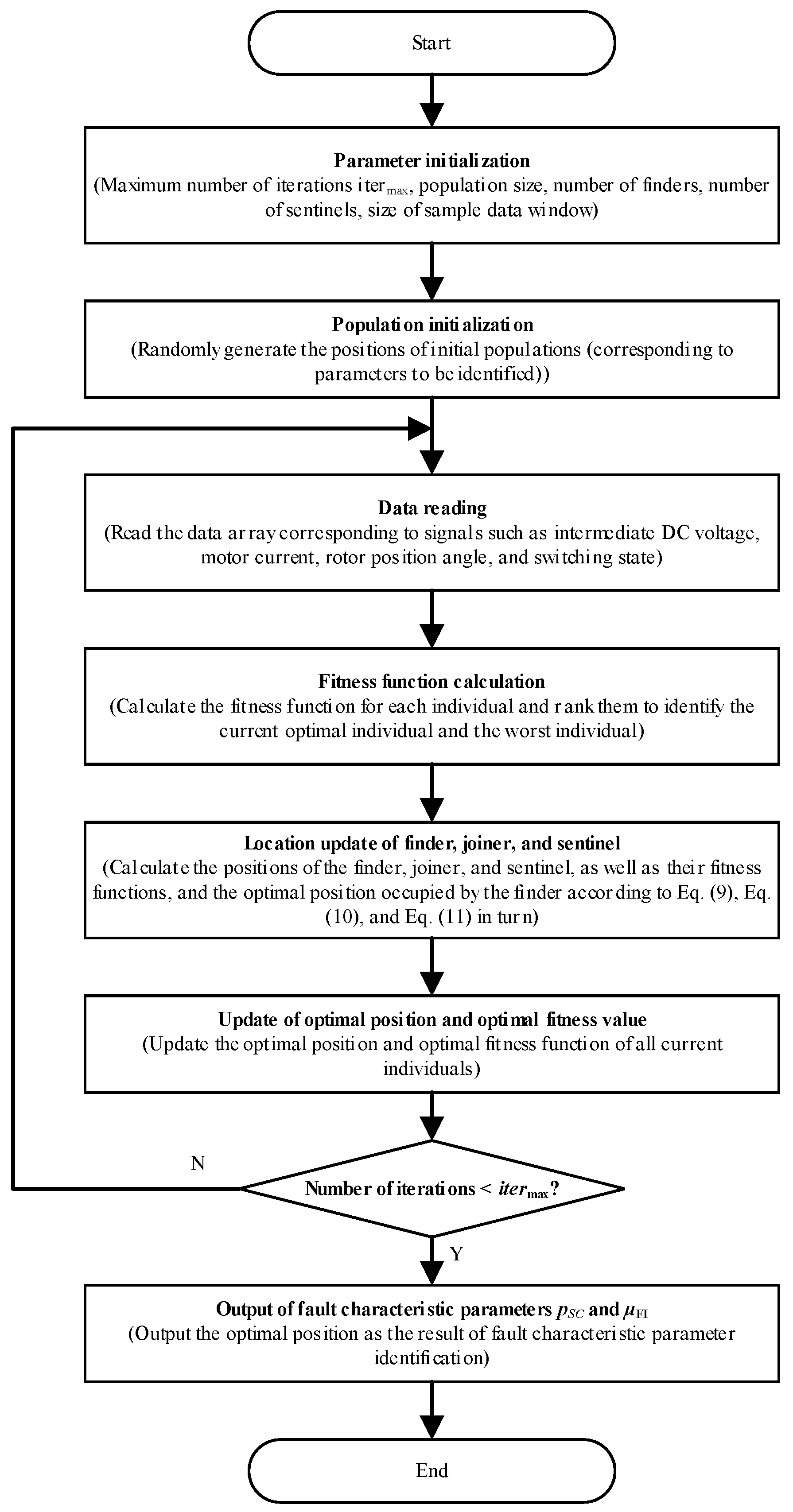
3.1. Basic Principles of SSA

We assume an optimization space for a d-dimensional matrix, where d represents the dimensionality of the variables to be optimized, with the number of sparrows n and the position shown in Equation (7).
x 1 , 1 x 1 , 2 x 1 , d x 2 , 1 x 2 , 2 x 2 , d x n , 1 x n , 2 x n , d
The sparrow fitness function can be expressed as follows:
F X = f ( [ x 1 , 1 x 1 , 2 x 1 , d ] ) f ( [ x 2 , 1 x 2 , 2 x 2 , d ] ) f ( [ x n , 1 x n , 2 x n , d ] )
where each row of FX represents an individual fitness value. In the SSA, the finders with better fitness values are given priority for finding food.
Finders typically make up 20% of the entire sparrow population [data supported by references]. With each iteration, the position of the finders is updated and can be described as follows:
x i , j k + 1 = x i , j k · exp i α · i t e r max , R 2 < S T x i , j k + Q · L       ,   R 2 S T
where k is the current number of iterations, and itermax is the maximum number of iterations and is a constant. x i , j k indicates the position of the i-th sparrow in the j-th dimension after the k-th iteration. α ∈ (0, 1] is a random number and R2 (R2 ∈ [0, 1]) and ST (ST ∈ [0.5, 1]) denote the warning value and the safety value, respectively. Q is a random number that follows a normal distribution. L denotes a 1×d matrix in which all elements are 1.
When R2 < ST, predators are absent, and the finder enters an extensive search pattern. If R2 ≥ ST, some sparrows have detected predators, forcing all to fly quickly to safe areas.
The remaining sparrows act as joiners, and their position is updated using Equation (10).
x i , j k + 1 = Q · exp x w o r s t x i , j k i 2 , i > n / 2 x p k + 1 + x i , j k x p k + 1 · A + · L , i n / 2
where x p k + 1 is the optimal position occupied by the finder, x w o r s t is the current global worst position, A represents a 1 × d matrix, where each element is randomly assigned to 1 or −1, and A + = A T ( A A T ) 1 . When i > n/2, the sparrows are extremely hungry, with low energy and poor fitness, and need to change their foraging positions to increase their energy.
The sparrows that sense danger are known as sentinels. Their initial positions are generated randomly within the population, and their position is updated using Equation (11).
x i , j k + 1 = x b e s t k + β · x i , j k x b e s t k , f i > f g x i , j k + K · x i , j k x w o r s t k ( f i f w ) + ε , f i = f g
where β, the controlling parameter of step size, is a normally distributed random number with a mean of 0 and variance of 1. K ∈ [−1, 1] is a random number. Here, fi is the fitness value of the current sparrow, while fg and fw are the current global best and worst fitness values, respectively. ε is the smallest constant so as to avoid division by zero.
For simplicity, when fi > fg, the sparrow is at the edge of the population. x w o r s t indicates the location of the population center in safety. If fi = fg, the sparrows positioned in the middle of the population are aware of danger and need to move closer to other individuals. K denotes the direction in which the sparrow moves and is also the step size control coefficient.

3.2. Fitness Function Design

In this subsection, a fitness function associated with fault characteristic parameters pSC and μFI is constructed for the relevant sensor and state information collected. Efforts are made to determine the optimal fitness function value, thereby facilitating the optimal identification of pSC and μFI.
The three-phase voltage of the normal working traction inverter can be described as follows:
V a = U d c / 3 · ( 2 S a S b S c ) V b = U d c / 3 · ( 2 S b S a S c ) V c = U d c / 3 · ( 2 S c S a S b )
where Va, Vb, and Vc refer to the three-phase output voltages of the inverter; Udc refers to the input power supply DC voltage; Sa, Sb, and Sc refer to the three-phase bridge arm switching states. S = 1 indicates that the upper tube is open and the lower tube is closed; S = 0 indicates that the upper tube is closed and the lower tube is open.
The application of the Clarke and Park transformations transforms the three-phase voltage from the abc stationary coordinate system to the dq two-phase synchronous rotating coordinate system, resulting in
V d V q = 2 3 cos θ   cos ( θ 2 π / 3 )   cos ( θ + 2 π / 3 ) sin θ sin ( θ 2 π / 3 ) sin ( θ + 2 π / 3 ) V a V b V c
where Vd and Vq are the d- and q-axis voltages, respectively.
Similarly, the application of Equation (13) transforms the motor’s three-phase stator currents ia, ib, and ic, into the dq two-phase synchronous rotating coordinate system, thus obtaining the d- and q-axis currents id and iq in the rotating coordinate system.
The inverter switching state, intermediate DC voltage, and rotor electrical position angle are collected in real time. Equations (12) and (13) are combined and low-pass filtering is applied after the calculations to eliminate the high-frequency effects of the switching signals, returning the estimated values V ˜ d and V ˜ q of Vd and Vq.
Model estimates V ^ d and V ^ q of Vd and Vq can be obtained on the basis of Equations (5), (6) and (13):
V ^ d V ^ q = f p ^ s c , μ ^ F I , V ˜ d , V ˜ q , i a , i b , i c , θ
where p ^ s c and μ ^ F I are the estimated location of the inter-turn short-circuit fault phase and the estimated fault severity value of the inter-turn short circuit, respectively. These two parameters are variables to be identified using SSA.
Combining V ˜ d and V ˜ q with Equation (14) creates the following fitness function:
F ( p ^ s c , μ ^ F I ) = 1 N C m = 1 N C V ˜ d ( m ) V ˜ d ( m ) 2 + V ˜ q ( m ) V ˜ q ( m ) 2
where NC represents the size of the data window, i.e., historical NC entries for the current time are taken for evaluation.

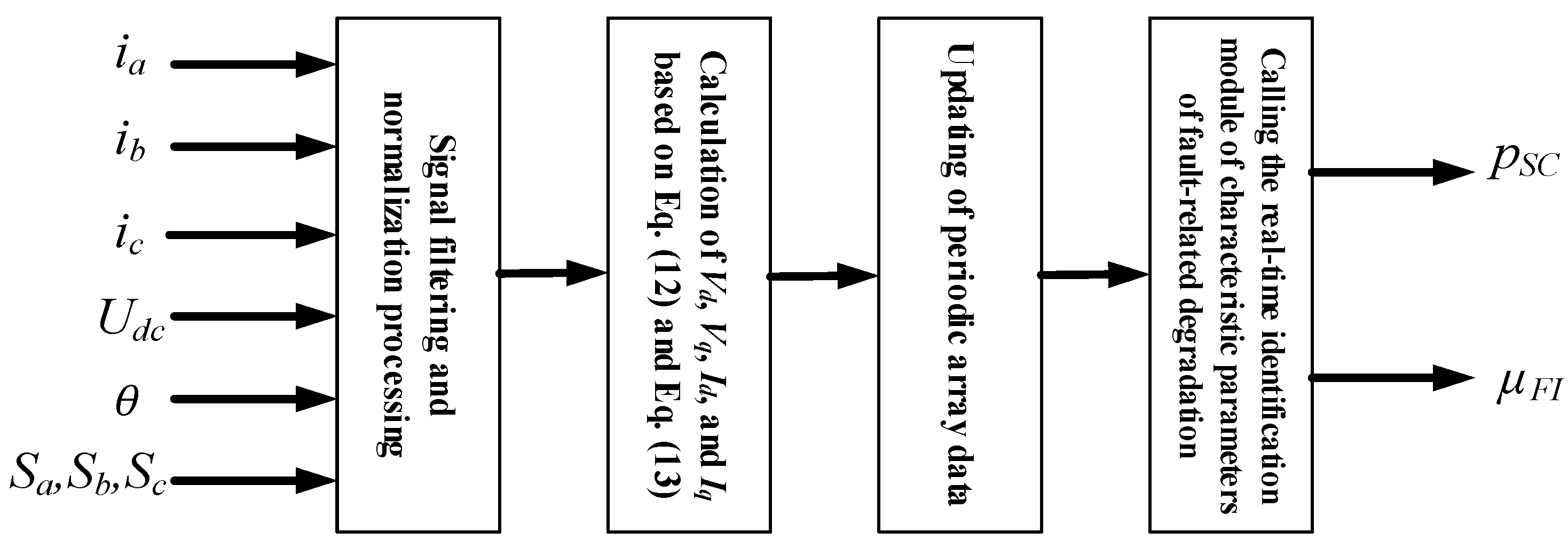
3.3. Real-Time Identification of Fault Characteristic Parameters

A complete fitness function design and SSA principles allow for a block diagram illustrating the real-time evaluation algorithm for degradation states caused by inter-turn short circuits in permanent magnet motors to be designed as in Figure 4. This diagram includes a module for the real-time identification of deterioration characteristic parameters. Figure 5 presents the implementation scheme for the module.

4. Experimental Verification

4.1. Diagnostic Objects and Algorithm Parameters

The permanent magnet synchronous motor of a particular traction drive system for a specific train model has been selected for verification in this section (relevant parameters provided in Table 1). Various degrees of degradation resulting from inter-turn short circuits are simulated by altering the insulation resistance Rf and the ratio of short-circuited turns μ. The algorithm proposed in this paper is then compared with the commonly used PSO algorithm. The main parameters of the algorithm are given in Table 2.

4.2. An Analysis and Discussion of the Test Results

For normal motor operation, simulate inter-turn short circuits in phase B winding with the ratio of short-circuited turns μ of 0.05, 0.1, 0.2, and 0.3 in sequence at t = 4 s, 4.1 s, 4.2 s, and 4.3 s. Various insulation resistances Rf will be applied to observe the diagnostic results under different degradation conditions, as illustrated in Figure 6, Figure 7 and Figure 8.
Figure 6 presents the comparative test results of the diagnostic algorithm when simulating fault insulation resistance for 0.35Ω. As observed in Figure 6a,b, no significant abnormalities are apparent in the current waveform of the three-phase motor when inter-turn short-circuit faults of varying severity are introduced at 4 s. It may be noted, however, that the fault-phase short-circuit current increases as the ratio of short-circuited turns μ rises. An analysis of Figure 6c,d has shown the SSA algorithm to achieve rapid convergence after approximately 40 iterations during the real-time identification of fault characteristic parameters for inter-turn short circuits of varying severity. In contrast, convergence may not be achieved within the specified number of iterations when the PSO algorithm is employed. The SSA parameter identification results presented in Figure 6e demonstrate that as the ratio of short-circuited turns μ changes, the method proposed is able to effectively track the real parameter value within approximately one calculation cycle and maintain stability. The relative error (AE) values for state evaluation remain below 5%, and the absolute error does not exceed 0.007. Conversely, when the PSO algorithm is utilized, its identification values fluctuate and tend to converge on various abnormal values, resulting in larger relative and absolute errors.
Figure 7 and Figure 8 show the results of tests simulating fault insulation resistances of 0.7 Ω and 1.4 Ω, respectively. It is clear from these figures that for the same ratio of short-circuited turns, a larger resistance results in a smaller fault current, which, in turn, leads to a reduced characteristic value for the inter-turn short circuit. The method proposed in this paper effectively identifies early characteristic fault parameters without exceeding 5% for state parameter estimation errors.

5. Conclusions

This paper has proposed a real-time diagnostic method for assessing inter-turn short-circuit faults with the use of online identification aimed at improving the early detection and real-time evaluation of the degradation state of permanent magnet synchronous motors. The method utilizes the SSA to evaluate the characteristic parameters of multiple strongly coupled faults in real time, and simulation experiments have validated its effectiveness. The following conclusions have been reached in this paper:
(1)
In the course of establishing a fault model for inter-turn short circuits in permanent magnet synchronous motors, this paper has uncovered the coupling influence of the ratio of short-circuited turns and insulation resistance on the degree of fault-related degradation. A corresponding quantitative index has also been designed to evaluate the degradation state and provide a theoretical basis for early warning in fault classification.
(2)
The proposed SSA-based method enables the real-time tracking of ITSC degradation with 95% accuracy, addressing the limitations of traditional optimization algorithms in nonlinear parameter identification. This approach provides a practical solution for enhancing the reliability of rail transit traction systems.
(3)
The method proposed mitigates the challenges the subtle nature of faults poses to detection in the early stages to quickly and accurately track the degradation state resulting from inter-turn short circuits, significantly enhancing diagnostic capabilities for inter-turn short circuits in permanent magnet synchronous motors at early stages and providing an effective safeguard for the reliability and safety of the rail transit traction system.
Subsequent experimental validation will be conducted on real permanent magnet synchronous motors to further assess the performance of the method proposed under real working conditions.
In future research, we will also consider using edge computing or other methods to implement the deployment of a machine learning-based traction drive system fault degradation monitoring algorithm.

Author Contributions

Conceptualization, Z.C. (Zhenglin Cheng) and X.L.; methodology, X.L.; software, X.L.; validation, Z.C. (Zhenglin Cheng) and X.L.; formal analysis, X.L.; investigation, X.L.; resources, X.L.; data curation, X.L.; writing—original draft preparation, X.L.; writing—review and editing, Z.C. (Zhiwen Chen); visualization, F.J.; supervision, K.L.; project administration, K.L.; funding acquisition, K.L. All authors have read and agreed to the published version of the manuscript.

Funding

This research was funded by National Natural Science Foundation of China under Grant 52407047, and Natural Science Foundation of Changsha under Grant kq2402066.

Data Availability Statement

No new data were created or analyzed in this study. Data are contained within the article.

Conflicts of Interest

Authors Zhenglin Cheng, Xueming Li and Fengbing Jiang were employed by the company CRRC Zhuzhou Electric Locomotive Institute Co., Ltd. The remaining authors declare that the research was conducted in the absence of any commercial or financial relationships that could be construed as a potential conflict of interest.

Abbreviations

The following abbreviations are used in this manuscript:
ITSCsinter-turn short circuits
SSASparrow Search Algorithm
PMSMspermanent-magnet synchronous motors

References

  1. Gan, W.; Li, X.; Wei, D.; Ding, R.; Liu, K.; Chen, Z. Real-Time Multi-Sensor Joint Fault Diagnosis Method for Permanent Magnet Traction Drive Systems Based on Structural Analysis. Sensors 2024, 24, 2878. [Google Scholar] [CrossRef] [PubMed]
  2. Arellano-Padilla, J.; Sumner, M.; Gerada, C. Winding Condition Monitoring Scheme for a Permanent Magnet Machine Using High-frequency Injection. IET Electr. Power Appl. 2011, 5, 89–99. [Google Scholar] [CrossRef]
  3. Gurusamy, V.; Bostanci, E.; Li, C.; Qi, Y.; Akin, B. A Stray Magnetic Flux Based Robust Diagnosis Method for Detection and Location of Interturn Short Circuit Fault in PMSM. IEEE Trans. Instrum. Meas. 2021, 70, 3500811. [Google Scholar] [CrossRef]
  4. Eldeeb, H.H.; Berzoy, A.; Mohammed, O. Stator Fault Detection on DTC-Driven IM via Magnetic Signatures Aided by 2-D FEA Co-simulation. IEEE Trans. Magn. 2019, 55, 8101505. [Google Scholar] [CrossRef]
  5. Irhoumah, M.; Pusca, R.; Lefevre, E.; Mercier, D.; Romary, R.; Demian, C. Information Fusion with Belief Functions for Detection of Interturn Short-Circuit Faults in Electrical Machines Using External Flux Sensors. IEEE Trans. Ind. Electron. 2018, 65, 2642–2652. [Google Scholar] [CrossRef]
  6. Urresty, J.C.; Riba, J.R.; Romeral, L. Diagnosis of Interturn Faults in PMSMs Operating Under Nonstationary Conditions by Applying Order Tracking Filtering. IEEE Trans. Power Electron. 2013, 28, 507–515. [Google Scholar] [CrossRef]
  7. Jeong, H.; Moon, S.; Kim, S.W. An Early Stage Interturn Fault Diagnosis of PMSMs by Using Negative-sequence Components. IEEE Trans. Ind. Electron. 2017, 64, 5701–5708. [Google Scholar] [CrossRef]
  8. Kemmetmuller, W.; Faustner, D.; Kugi, A. Modeling of a Permanent Magnet Synchronous Machine with Internal Magnets Using Magnetic Equivalent Circuits. IEEE Trans. Magn. 2014, 50, 8101314. [Google Scholar]
  9. Forstner, G.; Kugi, A.; Wolfgang, K. Magnetic Equivalent Circuit Based Modeling Framework for Electric Motors Applied to a PMSM with Winding Short Circuit. IEEE Trans. Power Electron. 2020, 35, 12285–12295. [Google Scholar] [CrossRef]
  10. Mazzoletti, M.A.; Bossio, G.R.; De Angelo, C.H.; Espinoza-Trejo, D.R. A Model-based Strategy for Interturn Short-circuit Fault Diagnosis in PMSM. IEEE Trans. Ind. Electron. 2017, 64, 7218–7228. [Google Scholar] [CrossRef]
  11. Moon, S.; Jeong, H.; Lee, H.; Kim, S.W. Interturn Short Fault Diagnosis in a PMSM by Voltage and Current Residual Analysis with the Faulty Winding Model. IEEE Trans. Energy Convers. 2017, 33, 190–198. [Google Scholar] [CrossRef]
  12. Guezmil, A.; Berriri, H.; Pusca, R.; Sakly, A.; Romary, R.; Mimouni, M.F. Detecting Inter-turn Short-circuit Fault in Induction Machine using High-order Sliding Mode Observer: Simulation and Experimental verification. J. Control Autom. Electr. Syst. 2017, 28, 532–540. [Google Scholar] [CrossRef]
  13. Abdallah, H.; Benatman, K. Stator Winding Inter-turn Short-circuit Detection in Induction Motors by Parameter Identification. IET Electr. Power Appl. 2017, 11, 272–288. [Google Scholar] [CrossRef]
  14. Kim, K.H. Simple Online Fault Detecting Scheme for Short-circuited Turn in a PMSM Through Current Harmonic Monitoring. IEEE Trans. Ind. Electron. 2011, 58, 2565–2568. [Google Scholar] [CrossRef]
  15. Alvarez-Gonzalez, F.; Griffo, A.; Wang, B. Permanent Magnet Synchronous Machine Stator Windings Fault Detection by Hilbert–Huang Transform. J. Eng. 2019, 17, 3505–3509. [Google Scholar] [CrossRef]
  16. Lee, H.; Jeong, H.; Koo, G.; Ban, J.; Kim, S.W. Attention Recurrent Neural Network-based Severity Estimation Method for Interturn Short-circuit Fault in PMSMs. IEEE Trans. Ind. Electron. 2020, 68, 3445–3453. [Google Scholar] [CrossRef]
  17. Mohammad-Alikhani, A.; Nahid-Mobarakeh, B.; Hsieh, M.-F. One-Dimensional LSTM-Regulated Deep Residual Network for Data-Driven Fault Detection in Electric Machines. IEEE Trans. Ind. Electron. 2024, 71, 3083–3092. [Google Scholar] [CrossRef]
  18. Fang, Y.; Wang, M.; Wei, L. Deep Transfer Learning in Inter-turn Short Circuit Fault Diagnosis of PMSM. In Proceedings of the 2021 IEEE International Conference on Mechatronics and Automation (ICMA), Takamatsu, Japan, 8–11 August 2021. [Google Scholar]
  19. Fadzail, N.F.; Zali, S.M.; Khairudin, M.A.; Hanafi, N.H. Stator Winding Fault Detection of Induction Generator Based Wind Turbine Using ANN. Indones. J. Electr. Eng. Comput. Sci. 2020, 19, 126. [Google Scholar] [CrossRef]
  20. Shih, K.-J.; Hsieh, M.-F.; Chen, B.-J.; Huang, S.-F. Machine Learning for Inter-turn Short-circuit Fault Diagnosis in Permanent Magnet Synchronous Motors. IEEE Trans. Magn. 2022, 58, 8204307. [Google Scholar] [CrossRef]
  21. Song, Q.; Wang, M.; Lai, W.; Zhao, S. On Bayesian Optimization-Based Residual CNN for Estimation of Inter-Turn Short Circuit Fault in PMSM. IEEE Trans. Power Electron. 2023, 38, 2456–2468. [Google Scholar] [CrossRef]
  22. Xue, J.; Shen, B. A Novel Swarm Intelligence Optimization Approach: Sparrow Search Algorithm. Syst. Sci. Control Eng. 2020, 8, 22–34. [Google Scholar] [CrossRef]
Figure 1. The main circuit and main components of a typical permanent magnet traction system.
Electronics 14 02095 g001
Figure 2. The PMSM equivalent model with a phase A inter-turn short circuit.
Electronics 14 02095 g002
Figure 3. A variation of evaluation index μFI for severity of fault-related degradation with Rf and μ.
Electronics 14 02095 g003
Figure 4. A block diagram of the real-time evaluation algorithm for degradation states caused by inter-turn short circuits in permanent magnet motors.
Electronics 14 02095 g004
Figure 5. The real-time identification module implementation scheme for fault characteristic parameters of inter-turn short circuits in permanent magnet motors.
Electronics 14 02095 g005
Figure 6. Comparative test results at insulation resistance Rf of 0.35 Ω.
Electronics 14 02095 g006aElectronics 14 02095 g006b
Figure 7. Comparative test results at insulation resistance Rf of 0.7 Ω.
Electronics 14 02095 g007aElectronics 14 02095 g007b
Figure 8. Comparative test results at insulation resistance Rf of 1.4 Ω.
Electronics 14 02095 g008aElectronics 14 02095 g008b
Table 1. Main parameters of given train traction drive system.
ParameterValueParameterValue
Rated power/kW1226Stator resistance/Ω0.02039
Rated speed/(r/min)1725Stator d-axis inductance/H0.00107
Rated torque/Nm6787Stator q-axis inductance/H0.00246
Rated current/A549Flux linkage of permanent magnet rotor/Wb1.073
Rated intermediate voltage/V1800Number of motor pole pairs4
Table 2. Algorithm parameters.
ParameterValueParameterValue
Calculation cycle/ms20Sampling cycle/us40
Population size (SSA, PSO)/Nr.20SSA finder/Nr.10
Maximum number of iterations (SSA, PSO)/time100SSA sentinel/Nr.5
PSO inertia weight w0.5SSA safety value0.8
PSO acceleration factors c1 and c22
Disclaimer/Publisher’s Note: The statements, opinions and data contained in all publications are solely those of the individual author(s) and contributor(s) and not of MDPI and/or the editor(s). MDPI and/or the editor(s) disclaim responsibility for any injury to people or property resulting from any ideas, methods, instructions or products referred to in the content.

